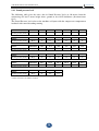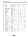
1
USER INSTRUCTIONS
&
MAINTENANCE
AIR COOLED CHILLER & HEAT PUMP
CFA - CHA
EN R14.13.M
USER INSTRUCTIONS AND MAINTENANCE
2
EN R14.13.M
USER INSTRUCTIONS AND MAINTENANCE
GENERAL TABLE OF CONTENTS
1. CE model plate
Pag.
04
2.
Safety notes
Pag.
05
3.
Symbols on the unit
Pag.
06
Pag.
08
4. User and maintenance manual
3
EN R14.13.M
USER INSTRUCTIONS AND MAINTENANCE
1. CE MODEL PLATE
4
EN R14.13.M
USER INSTRUCTIONS AND MAINTENANCE
2. SAFETY NOTES
Note sulla sicurezza per l’utilizzo della macchina
Read this Manual carefully before using the unit!
Keep the manual safe and ready for consultation for all future requirements!
ALWAYS PROVIDE CUT-OUTS SO THAT THE POWER FEEDING LINE OF
THE UNIT CAN BE DISCONNECTED FROM THE ELECTRICAL MAINS
SUPPLY, EVEN IN THE PRESENCE OF A UNIT ON/OFF CONTROL
TRANSMITTED FROM THE CUSTOMER’S REMOTE STATION.
ALWAYS DISCONNECT THE ELECTRICAL POWER SUPPLY BEFORE
CARRYING OUT MAINTENANCE!For details, refer to the unit’s wiring diagrams.
(1) Keep the unit in a VERTICAL POSITION during loading and unloading procedures
and check that installation surface is perfectly HORIZONTAL with a spirit level;
(2) Install the unit in a place that allows proper ventilation of the condensers! Do not
install the unit indoors or in a poorly ventilated place!
(3) Do not inspect the unit electrical panel with wet or moist hands (risk of electric shock);
(4) When the unit is running do not place objects on the top (object may fall with resulting
damage to the unit and injury to operators);
(5) Maintenance must be performed ONLY by skilled personnel. When the covers of the
electrical panels or external condenser/fans compartment are opened by a maintenance
technician, other maintenance personnel or other persons in the area must be notified of the
potential hazard my means of specific warning notices!
(6) Do not use tools or objects to touch the fan impeller blades (risk of injury to persons or
damage to property or the unit).
(7) THE UNIT IS NOT SUITABLE FOR USE IN EXPLOSIVE ATMOSPHERES!
(8) The units are designed and approved for operation in industrial and residential
environments. For more information, consult the Engineering Department.
(9) The Manufacturer provides one year of warranty from the date of shipment and the
warranty will be held valid only if no repairs or modifications of the unit have been carried
out by personnel not authorised by the Manufacturer. To avoid problems, possible accidents,
or injury to persons, consult our technical personnel for authorisations for possible
alterations or refittings, repairs, removal of components or disassembly of the entire unit.
10) THE UNIT CONTAINS FLUORINATED GASES (R410A) THE
GREENHOUSE EFFECT OF WHICH IS REGULATED BY THE PROVISIONS
OF THE KYOTO PROTOCOL! (REGULATION 842/2006/EC)
5
EN R14.13.M
USER INSTRUCTIONS AND MAINTENANCE
3. SYMBOLS ON THE UNIT BODY
#
1
2
3
4
5
GRAFICA
SYMBOL
SYMBOL
SÍMBOLO
DESSIN
FUNZIONE
FUNCTION
FUNKTION
FUNCIÓN
FONCTION
Ingresso cavo elettrico
Electric cable inlet
Eingang Stromkabel
Entrada cable eléctrico
Entrée câble électrique
PERICOLO, PRESTARE ATTENZIONE!
DANGER, PAY ATTENTION!
GEFAHR, VORSICHT!
¡PELIGRO, PRESTAR ATENCIÓN!
DANGER, FAIRE ATTENTION !
Pericolo ALTA TENSIONE sui
componenenti!
HIGH VOLTAGE on components!
Gefahr HOCHSPANNUNG an den
Bauteilen!
¡Peligro ALTA TENSIÓN en los
componentes!
Danger HAUTE TENSION sur les
composants !
Senso di rotazione
Rotation direction
Drehrichtung
Sentido de rotación
Sens de rotation
Sollevamento (impiego dei golfari)
Hoisting point (use eyebolts)
Heben (Hebeösen verwenden)
Elevación (uso de los cáncamos)
Levage (emploi des anneaux)
IMPORTANT WARNINGS
The indication IMPORTANT WARNINGS is used to focus
attention on actions or hazards that could damage the unit or its
equipment
ENVIRONMENTAL PROTECTION
The indication Environmental Protection supplies instructions
for use of the machine.
6
EN R14.13.M
USER INSTRUCTIONS AND MAINTENANCE
4. USER AND MAINTENANCE MANUAL
CONTENTS OF THE MANUAL
CONTENTS OF THE MANUAL .................................................................................. 07
1. Introduction to the range ............................................................................................ 09
1.1 Description of the units ..................................................................................... 09
1.2 Identification of the units .................................................................................. 11
1.3 Operating conditions and limits ....................................................................... 12
1.4 Unit performance .............................................................................................. 14
1.4.1 Cooling duty and electrical power consumption values ............................................. 14
1.4.2 Heating duty and electrical power consumption values ............................................. 15
1.4.3 Sound pressure level .......................................................................................... 16
2. Installation requirements ........................................................................................... 17
2.1 Lifting abd transport ......................................................................................... 18
2.2 Installation and positioning............................................................................... 20
2.3 Hydraulic connections ...................................................................................... 22
2.3.1 Water filling ..................................................................................................... 22
2.3.2 Water drain ...................................................................................................... 22
2.4 Installation of the electrical parts ...................................................................... 23
3. Commissioning and running the unit ......................................................................... 25
3.1 Start-up and operation notes ............................................................................ 25
3.2 Description of the electrical panel and controller ............................................ 26
3.2.1 Operation and regulation .................................................................................... 26
3.2.2 Unit ON/OFF ................................................................................................... 26
3.2.3 User display ..................................................................................................... 27
3.2.4 Parameters programming and saving procedure....................................................... 27
3.2.5 Programming the Set-Point ................................................................................. 28
3.2.6 Probes reading .................................................................................................. 29
3.2.7 Alarm display ................................................................................................... 30
3.3 Operating features ............................................................................................ 32
3.3.1 Display temperature........................................................................................... 32
3.3.2 Set-Point cooling mode (Chiller & Heat Pump) ....................................................... 32
3.3.3 Set-Point heating mode (Heat Pump) .................................................................... 32
3.3.4 Compressor start time lag ................................................................................... 32
7
EN R14.13.M
USER INSTRUCTIONS AND MAINTENANCE
3.3.5 Antifreeze function ............................................................................................ 32
3.3.6 Antifreeze function with support heaters (Option) .................................................. 33
3.3.7 No-flow protection .......................................................................................... 33
3.3.8 Regulation and control of the pump ..................................................................... 33
3.3.9 Fan(s) ON/OFF ............................................................................................... 34
3.3.10 Fan(s) speed control (Option)............................................................................. 34
3.3.11 Set point compensation (Option) ......................................................................... 35
3.3.12 Water filling kit (Option) ................................................................................... 35
3.3.13 Water strainer (Option) ..................................................................................... 36
3.3.15 Spurge valve (Option) ...................................................................................... 36
3.3.16 Double set point (Option) .................................................................................. 37
3.3.17 Phase sequence control (Option) ......................................................................... 37
3.3.18 Secondary pump control (Option) ....................................................................... 37
3.4 Operative settings of the controller .................................................................. 38
3.4.1 Menu structure.................................................................................................. 38
3.4.1 Parameters ....................................................................................................... 39
3.5 Trouble shooting .............................................................................................. 45
4. Maintenance ............................................................................................................... 48
4.1 Periodic clearing of the unit ............................................................................. 49
4.1.1 Periodic inspection and cleaning of the coils ........................................................... 49
4.1.2 Inspection and washing og the water exchanger
...................................................... 49
4.2 Compressor damage ......................................................................................... 49
4.2.1 Lubrication and removal of the oil ........................................................................ 50
4.3 Procedures in the event prolonged inactivity of installed units ........................ 50
4.3.1 Preliminary check (Pre Start-up) .......................................................................... 51
5. Warranty .................................................................................................................... 52
6. Scrapping/Disposal of the unit at the end of its working life .................................... 53
6.1 Disposal of fluids .............................................................................................. 53
6.1.1 Emptying of refrigerant ...................................................................................... 53
6.1.2 Compressor lubricating oil .................................................................................. 53
6.2 Scrapping of the unit ......................................................................................... 54
APPENDIX I / R410a Technical data sheet ................................................................... 55
8
EN R14.13.M
USER INSTRUCTIONS AND MAINTENANCE
1. Introduction to the range
1.1 Description of the units
The series constitutes a range of air-cooled water chillers designed to meet the requirements of
low and medium capacity process cooling and air conditioning plants, operating with R410A, a
non-flammable and non-toxic high efficiency refrigerant for optimal energy saving in
operation of the unit.
The entire range is composed of a wide range of models characterised by the use of scroll
compressors, with one or two separate refrigerant circuits, and plate evaporators in brazed AISI
stainless steel.
The fans installed are of the axial low-noise type.
The equipment can consist of a pump, pump with storage tank, dual pump, or dual pump with
storage tank.
The pump and storage tank assembly is designated “hydronic kit”.
Control of the chillers is provided by an electronic microprocessor controller.
The refrigerant and hydraulic circuits comply with the PED directive.
Special or LT (low water temperature) units are available on different type of refrigerant gas,
compressors and evaporators depending on the application.
Compressors
The standard compressors are of the hermetic scroll type with orbital scrolls. The rotating scroll
is driven by a two-pole motor cooled by the refrigerant on the suction line. All the compressors
are complete with a crankcase heater to prevent mixing of oil with the refrigerant during
stoppages, electronic thermal protection (if part of the equipment) and thermal overload
protection.
All models in the range with multiple compressors are provided with the unloading function.
When a high condensing temperature is reached (as established by a pressure switch) due to
abnormally high ambient temperature, one compressor stops on each circuit. This results in
oversizing of the condensing coil surface area and dropping of the condensing temperature.
Output in these conditions is slightly higher than 50% of total output but it becomes
unnecessary to stop the unit so that cooling can continue throughout the critical period.
The compressors are filled with polyester oil (POE), which is suitable for use in conjunction
with R410A.
Special or LT (low water temperature) units are available on different type of refrigerant gas,
compressors and evaporators depending on the application.
Water-refrigerant plate evaporator
The evaporators are composed of AISI 316 stainless steel brazed plate exchangers. The
exchangers are clad externally with an anticondensation mat made of closed cell expanded
foam.
The exchanger is protected by a series of temperature probes installed on the refrigerant
discharge having an anti-freeze function, and by a pressure switch monitoring the pressure
differential between refrigerant suction and discharge sides.
Special or LT (low water temperature) are available on different type of evaporator depending
on the application
9
EN R14.13.M
USER INSTRUCTIONS AND MAINTENANCE
Air-cooled condenser
The air-cooled condenser is composed of a finned core coil made with copper tubes and
high-efficiency corrugated aluminium fins adequately spaced in such a way as to ensure
optimal heat exchange efficiency. The copper tubes are of sufficient diameter and wall
thickness to withstand the highest R410A resign pressures.
Options:
• Metal mesh filters
• Prepaited condensing coils
• Electrophoresis on the condensing coils
Axial Fans
Axial fans with IP 54 protection rating, external rotor, with moulded blades made of
fibreglass-reinforced plastic with a die cast aluminium core.
The fans are accommodated in dynamically profiled external ports complete with a safety mesh
protecting the exterior side.
Electrical cabinet for power and control circuits
Electrical power and control cabinet, made in compliance with EN 60204-1/IEC 204-1 (Safety
of Machinery), complete with:
- control circuit transformer;
- main door-lock circuit breaker;
- thermal-magnetic cut-outs or fuses protecting compressors, fans and pumps
- contractors controlling compressors, fans and pumps;
- terminals for common alarms block;
- terminals for remote On/Off input;
- control circuit terminal boards;
- exterior quality electrical cabinet with single door and weather seals;
- electronic controller;
- control circuit numbered cables;
- 400/3/50Hz power supply; 230 Vac and 24 Vac control circuits for the electronic controller.
Options:
• phase sequence monitoring;
• electrical cabinet fan;
• electrical cabinet anticondensation heater;
• remote keypad kit.
Microprocessor controller
All units series units are equipped with a microprocessor controller capable of managing the
following functions:
-water temperature control in the traditional method with a probe on the system return line
(especially suitable for applications in which an inertia storage tank is installed);
-fans ON-OFF control;
-freeze protection;
-automatic compressors start sequence rotation;
-compressor time intervals;
-alarms signalling and reset;
-presentation on the display of the programmed set-points and the values read by the probes.
10
EN R14.13.M
USER INSTRUCTIONS AND MAINTENANCE
1.2 Identification of the units
CHILLER / HEAT PUMP
CFA CHA
12 1 2
S P-B ST
3
4
5
20
6
1
7
MAP3
8
1 – MODEL
CF – Water chiller
CH – Heat pump
2 – CONDENSING MODE
A = Air cooled unit
W= Water cooled unit
3 – COMPRESSORS TYPE
S = Hermetic scroll
V = Semi-hermetic double screw
P = Alternative piston
4 – EVAPORATOR-CONDENSER TYPE
P-B = Plate-Finned coils
P-P = Plate-Plate
F-B = Shell&tube-Finned coils
F-F = Shell&tube-shell&tube
5 – VERSION
ST= Standard unit (axial fans CFA/CHA models - water condenser CFW/CHW models)
MC = Condensing unit (remote evaporator)
ME = Condenser less unit (remote condenser)
FC = Free-cooling unit (axial fans)
CV = Unit with centrifugal fans
LT = Unit suitable for low water temperature (Brine chiller)
SP = Special unit
6 – COOLING CAPACITY
Numerical value denoting the cooping capacity in kW in nominal conditions (water 12/7 °C
and ambient 35 °C)
7 – NUMBER OF COMPRESSORS
1 = one compressor
2 = two compressors
4 = for compressors
8 – HYDRAULIC MODULE
MB = Basic unit, without hydraulic module
MP2 (MDP2) = Unit with P2 pump 2 nominal bar pressure (double P2)
MP3 (MDP3) = Unit with P3 pump 3 nominal bar pressure (double P3)
MP5 (MDP5) = Unit with P5 pump 3 nominal bar pressure r (double P5)
MAP2 (MADP2) = Unit with storage tank and P2 pump 2 nominal bar pressure (double P2)
MAP3 (MADP3) = Unit with storage tank and P3 pump 2 nominal bar pressure (double P3)
MAP5 (MADP5) = Unit with storage tank and P5 pump 5 nominal bar pressure (double P5)
11
EN R14.13.M
USER INSTRUCTIONS AND MAINTENANCE
1.3 Operating conditions and limits
Operating limits in Cooling mode
CHILLER
Water inlet temperature
Water outlet temperature
Temperature gradient
Ambient air temperature
°C
°C
°C
°C
MIN
5/-5(*)
0/-9(*)
4
-5 / -20 (**)
MAX
25
15
8
(***)
(*) With Double set-point option
If water temperature is below to +5 °C, i’s complulsory to use glycol on the right percentage, as per the table in the
next page
(**) First value refers to standard unit. Second value refers to unit with fans electronic control, antifreeze heater on
pump and storage tank (when present).
(***) Value depends on size of chiller and operating conditions.
Operating limits in Heating mode
HEAT PUMP
Water inlet temperature
Water outlet temperature
Temperature gradient
Ambient air temperature
°C
°C
°C
°C
MIN
MAX
25
45
30 50 (***) / 40 (****)
4
8
-5
20
(***) Max hot water outlet temperature with minimum ambient air temperature of +5 °C
(****) Max hot water outlet temperature with minimum ambient air temperature of -5 °C
In the presence of a risk of freezing of the fluid medium in the hydraulic circuit antifreeze
mixtures are required; the following are guideline values of the freezing point for mixtures of
water and ethylene glycol, withy glycol percentages expressed in weight. To avoid pump
damage in the event of glycol percentages above 25%, consult the Sales Department.
The use of this type of mixture causes slight alterations in some of the thermodynamic
parameters of the chillers. The new values can be established by multiplying the value of the
required parameter in nominal operating conditions by the appropriate coefficients shown in
the following table:
12
EN R14.13.M
USER INSTRUCTIONS AND MAINTENANCE
% GLYCOL by weight
10
20
30
40
50
Freezing temperature (°C)
Cooling capacity correction factor
Absorbed power correction factor
Mixture flow rate correction factor
Pressure drops correction factor
-3,7
0,99
0,99
1,02
1,083
-8,7
0,98
0,98
1,05
1,165
-15,3
0,97
0,98
1.07
1,248
-23,5
0,96
0,97
1,11
1,33
-35,6
0,93
0,95
1,13
1,413
WARNING! WITHOUT GLYCOL IN THE SYSTEM:
IMPORTANT!
If the unit is not used in the winter the water in the circuit may freeze
IMPORTANT!
The use of mixtures of water with glycol affects performance
characteristics of the unit
13
EN R14.13.M
USER INSTRUCTIONS AND MAINTENANCE
1.4 Unit performance
1.4.1 Cooling duty and electrical power consumption values
The chiller performance depend mainly from the water flow rate, water temperature and
ambient temperature.
These values are defined during the commercial offer and it must refer to them.
Performance values of the models in the range of chillers are shown below referred to water
inlet/outlet temperature of 12/7 °C and ambient temperature of 35 °C
CFA
2.1
3.1
4.1
5.1
6.1
8.1
Cooling capacity
kW
1,9
2,7
3,9
5,1
6,1
7,8
Adsorbed
compressor(s) power
kW
0,7
0,9
1,4
1,9
2,3
2,8
CFA
10.1
13.1
15.1
20.1
26.1
30.1
Cooling capacity
kW
9,2
13,1
15,2
19,7
26,1
30,2
Adsorbed
compressor(s) power
kW
3,2
4,5
5,3
6,4
8,8
9,6
CFA
34.1
39.1
45.2
53.2
59.2
66.2
Cooling capacity
kW
33,3
39,3
43,3
52,7
58,3
66,1
Adsorbed
compressor(s) power
kW
10,7
12,8
15,4
16,5
19,4
21,6
CFA
75.2
90.2
98.2
110.2
126.2
145.2
Cooling capacity
kW
75,0
89,1
97,4
110
125,7
144,2
Adsorbed
compressor(s) power
kW
26,5
28,7
33,5
37,8
40,8
46,5
CFA
158.2
180.4
195.4
220.4
250.4
290.4
Cooling capacity
kW
157,6
176,0
199,8
220
249,3
288,4
Adsorbed
compressor(s) power
kW
54,5
58,7
64,7
75,7
82,3
92,9
CFA
315.4
376.4
412.4
Cooling capacity
kW
315,2
375,5
412,0
Adsorbed
compressor(s) power
kW
109,0
116,0
135,2
Model
Model
Model
Model
Model
Model
14
EN R14.13.M
USER INSTRUCTIONS AND MAINTENANCE
1.4.2 Heating duty and electrical power consumption values
The heat pump performance depend mainly from the water flow rate, water temperature and
ambient temperature.
These values are defined during the commercial offer and it must refer to them.
Performance values of the models in the range of heat pumps are shown below referred to
water inlet/outlet temperature of 40/45 °C and ambient temperature of 7 °C (UR 87%)
CHA
2.1
3.1
4.1
5.1
6.1
8.1
Heating capacity
kW
NA
NA
NA
5,6
6,9
8,8
Adsorbed
compressor(s) power
kW
NA
NA
NA
1,9
2,2
2,7
CHA
10.1
13.1
15.1
20.1
26.1
30.1
Heating capacity
kW
9,9
14,5
17,1
21,6
29
32,7
Adsorbed
compressor(s) power
kW
3
4,5
5,1
6,3
8,3
9,4
CHA
34.1
39.1
45.2
53.2
59.2
66.2
Heating capacity
kW
39,7
43,5
49,3
59,8
66,7
74,5
Adsorbed
compressor(s) power
kW
10,3
12,1
14,3
16,3
18,3
20,2
CHA
75.2
90.2
98.2
110.2
126.2
145.2
Heating capacity
kW
86
101
111
125,7
140,4
163
Adsorbed
compressor(s) power
kW
23,7
27,2
30,7
34,7
39
44,3
CHA
158.2
180.4
195.4
220.4
250.4
290.4
Heating capacity
kW
178,4
198,8
225
251,3
280,8
325,8
Adsorbed
compressor(s) power
kW
49,5
55,1
62,1
69,5
77,6
88,6
CHA
315.4
376.4
412.4
Heating capacity
kW
356,8
NA
NA
Adsorbed
compressor(s) power
kW
99,2
NA
NA
Model
Model
Model
Model
Model
Model
15
EN R14.13.M
USER INSTRUCTIONS AND MAINTENANCE
1.4.3 Sound pressure level
The following table gives the noise data in Sound Pressure Lp(A) at 10 meters from the
condensing coil and 1 metre height above ground in free field conditions (direction factor
Q=2).
The Sound Pressure level refers to the machine std layout with the compressors compartment
insulated with sound absorbing matting.
Model
Sound pressure (10 m)
Model
Sound pressure (10 m)
Model
Sound pressure (10 m)
Model
Sound pressure (10 m)
Model
Sound pressure (10 m)
Model
Sound pressure (10 m)
CFA/CHA
2.1
3.1
4.1
5.1
6.1
8.1
dB(A)
42*
42*
42*
43
43
46
CFA/CHA
10.1
13.1
15.1
20.1
26.1
30.1
dB(A)
47
47
47
47
48
48
CFA/CHA
34.1
39.1
45.2
53.2
59.2
66.2
dB(A)
48
49
49
47
48
49
CFA/CHA
75.2
90.2
98.2
110.2
126.2
145.2
dB(A)
49
52
54
56
57
57
CFA/CHA
158.2
180.4
195.4
220.4
250.4
290.4
dB(A)
57
58
58
59
60
60
CFA/CHA
315.4
376.4
412.4
dB(A)
61
63*
63*
* Values referred to the chiller execution
16
EN R14.13.M
USER INSTRUCTIONS AND MAINTENANCE
2. Installation Requirements
2.1 Lifting and transport
Before lifting the unit refer to the following WEIGHTS table, wherein values are calculated
without the hydraulic unit:
17
EN R14.13.M
USER INSTRUCTIONS AND MAINTENANCE
Model
2.1
3.1
4.1
5.1
6.1
8.1
Weight (basic unit*) CFA
kg
150
160
165
180
190
200
Weight (basic unit*) CHA
kg
ND
ND
ND
200
210
220
10.1
13.1
15.1
20.1
26.1
30.1
Model
Weight (basic unit*) CFA
kg
230
240
255
350
365
380
Weight (basic unit*) CHA
kg
250
265
280
380
400
415
34.1
39.1
45.2
53.2
59.2
66.2
Model
Weight (basic unit*) CFA
kg
460
480
560
620
635
655
Weight (basic unit*) CHA
kg
500
530
620
670
685
720
75.2
90.2
98.2
110.2
126.2
145.2
Model
Weight (basic unit*) CFA
kg
680
870
950
1020
1100
1160
Weight (basic unit*) CHA
kg
740
940
1030
1100
1190
1255
158.2
180.4
195.4
220.4
250.4
290.4
Model
Weight (basic unit*) CFA
kg
1180
1360
1570
1630
2050
2100
Weight (basic unit*) CHA
kg
1280
1600
1780
1880
2250
2290
315.4
376.4
412.4
Model
Weight (basic unit*) CFA
kg
2210
2630
2680
Weight (basic unit*) CHA
kg
2450
ND
ND
* Basic unit: provided with plate evaporator, differntial pressure switch, 4-way valve (only for heat pumps)
18
EN R14.13.M
USER INSTRUCTIONS AND MAINTENANCE
DANGER!
The unit must be handled with care to avoid damage to the external structure and the
internal mechanical end electrical components. Also make sure that there are no
obstacles or persons along the route, to avoid the risk of collision, crushing or
overturning of the lifting and handling vehicle.
The unit can be handled and/or lifted exclusively using the specific lifting attachments
incorporated in the frame.
Lifting of the unit is possible by means of textile webbing inserted in the channels in the base
frame, or by means of the forks of a suitable lift truck.
Once the unit has been installed remove the protective film from the panelling and the shrink
wrap plastic.
ENVIRONMENTAL PROTECTION
Dispose of the packing materials in compliance with national legislation and local bylaws
in your country.
DANGER!
Keep packaging materials out of reach of children.
19
EN R14.13.M
USER INSTRUCTIONS AND MAINTENANCE
2.2 Installation and positioning
(1) The unit must be installed in a site with good air quality without a corrosive or inflammable
or exceptionally dusty atmosphere.
THE UNIT IS NOT SUITABLE FOR USE IN EXPLOSIVE ATMOSPHERES!
(2) The unit must be installed in a site in which ventilation is sufficient and the heat release by
the unit can be easily dispersed to the exterior. Considering that the chiller disperses heat to the
exterior when it is running, if the place of installation is confined or lacks sufficient fresh air,
the room temperature will rise progressively and the hot air, which will recirculate over the
condenser, will cause rapid degradation of the performance to the point at which the unit shuts
down due to high pressure.
IMPORTANT !
The unit must be sited taking account of the minimum
recommended clearances, taking account of the position of the
condensing coils and accessibility of the hydraulic and electrical
connections.
An installation without the recommended clearances will cause poor operation of the unit with
an increase in power consumption and a reduction in cooling capacity due to an increase in the
condensing pressure.
The area above the unit must be completely free of obstacles in such a way as to guarantee
unimpeded air flow from the condensing fans.
If the unit is surrounded by walls, the minimum clearances shown are still valid as long as at
least the two adjoining walls closest to the unit are no higher than the total height of the unit.
Greater spaces than the spaces indicated must be provided to allow handling of any
components to be replaced.
20
EN R14.13.M
USER INSTRUCTIONS AND MAINTENANCE
MODEL
Installation
clearances
L1
L2
L3
L4
CFA/CHA
mm
mm
mm
mm
MODEL
Installation
clearances
L1
L2
L3
L4
2.1 - 45.2 53.2 - 75.2 90.2-110.2
1000
1000
800
1000
1000
1000
800
1000
CFA/CHA
mm
mm
mm
mm
1000
1200
800
1000
126.2-158.2
180.4-220.4
1000
1200
800
1000
1000
1200
800
1000
250.4-315.4 376.4-412.4
1000
1200
800
1200
1000
1200
800
1200
(3) To ensure a sufficient air flow the condenser fins must NEVER be obstructed or excessively
fouled;
(4) Free air circulation around the electrical cabinet must be guaranteed.
21
EN R14.13.M
USER INSTRUCTIONS AND MAINTENANCE
2.3 Hydraulic connections
All hydraulic connections are at care of the customer.
Connect the unit to the water pipes observing the direction as indicated in the cooling circuit.
Check the yellow labels on the inlet/outlet unit.
Provide inlet/outlet valves in order to do an easy maintenance without draining the unit.
It’s mandatory to install an 0.5-0.8 mm mesh filter on the chiller water inlet. It can be supply as
an option of the unit.
2.3.1 Water filling
Basic unit: provided with evaporator and pressure differential (or flow switch). The water
filling can be outside the unit (at customer’s care) or inside the unit by a filling kit (suitable as
an option of the unit see the paragrafe “Water filling kit”). Use the air vent (check the position
in the cooling circuit) to help the venting procedure.
Unit with pump (double pumps): provided with evaporator, differential pressure switch (or flow
switch) and pump (double pumps). The water filling can be outside the unit (at customer’s care)
or inside the unit by a filling kit (suitable as an option of the unit see the paragrafe 3.3.9 “Water
filling kit”). Use the air vent (check the position in the cooling circuit) to help the venting
procedure.
Unit with pump (double pumps) and storage tank: provided with evaporator, differential
pressure switch (or flow switch), pump (double pumps) and storage tank. The water filling can
be outside the unit (at customer’s care) or inside the unit by a filling kit (suitable as an option of
the unit see the paragrafe “Water filling kit”). Use the air vent (check the position in the cooling
circuit) to help the venting procedure.
The maximum admissible internal hydraulic pressure is 6 bar.
2.3.2 Water drain
Basic unit: provided with evaporator and differential pressure or flow switch. The drain valve
is placed under the evaporator.
Unit with pump (double pump): provided with evaporator, differential pressure or flow switch
and pump (double pump). The drain valves are placed under the evaporator and the pump.
Unit with pump (double pump) and storage tank: provided with evaporator, differential
pressure or flow switch, pump (double pump) and storage tank. The drain valves are placed
under the evaporator, the pump, and the storage tank or outside the unit (purge valve on the
units with filling kit).
WARNING! For the whole water drain of the unit is necessary to use all of the valves
provided on evaporator / storage tank / pump. The partial water drain of the unit may
result in the risk of freezing and subsequent collapse of some of its parts (see paragraph
1.3 "Terms of Use and Limits").
Check on the unit yellow label representatives drainage points.
22
EN R14.13.M
USER INSTRUCTIONS AND MAINTENANCE
2.4 Installation of the electrical parts
The units are completely wired in the factory. The only cable required is the connection to the
electrical mains supply, the connection of the flow switch (optional) and the remote On/Off
switch (ON-OFF jumpered by default). All operations described above must be carried out by
qualified personnel in compliance with statutory legislation. For all electrical work refer to the
wiring diagrams.
General warning or precautions to be strictly observed.
Serious hazard.
Electric shock hazard.
THE UNIT ELECTRICAL HOOK-UP MUST BE CARRIED OUT BY A LICENSED
ELECTRICIAN WITH THE NECESSARY PROFESSIONAL SKILLS AND IN
COMPLIANCE WITH STATUTORY REGULATIONS IN THE COUNTRY OF
INSTALLATION !
IMPORTANT ! FOR INSTALLATION REFER TO THE UNIT WIRING
DIAGRAMS SUPPLIED ON BOARD THE UNIT TOGETHER WITH THIS
MANUAL, AND TO THE DATA ON THE CE RATING PLATE
(1) The unit must be connected to the power supply only when the installation work
(mechanical, hydraulic and electrical) has been completed.
(2) The electronic control board is located in the chiller electrical cabinet.
Only qualified technicians must open the unit to perform work on it. To hook up
the unit to the mains electrical panel, for power feeding and for the signals
input/output, always refer to the wiring diagram.
(3) Comply with the connection specifications for the phase and protective earth
conductors. There must be a specific protection against short circuits and ground
faults upline from the power feeding line, capable of disconnecting the plant from
all other users.
(4) Install suitable protection on the unit power feeding line in compliance with the
regulations in force in the country in which the unit is installed.
(5) For the electrical connections use cables that comply with the statutory electrical
regulations in force in the country of installation
(6) After installation, check that the mains power values are within a tolerance of
23
EN R14.13.M
USER INSTRUCTIONS AND MAINTENANCE
±10% of the nominal machine input voltage (unless otherwise specified on the
electrical wiring diagram) with a maximum phase-to-phase imbalance of 3%. If
these parameters are not present, contact your local electricity company.
(7) No external thermostat can be used to connect/disconnect the unit’s power feeding
line, or malfunctions and poor performance of the unit will result.
(8) Keep the power lines separate from the signal cables; signal cables must be
shielded and connected to a voltage-free PE point at just one end of the shield.
(9) It is mandatory to make an efficient protective earth connection. The manufacture
cannot be held liable for any damage caused by the omitted or inefficient
connection of the unit to the earth system.
24
EN R14.13.M
USER INSTRUCTIONS AND MAINTENANCE
3. Commissioning and running the unit
3.1 Start-up and operation notes
Before starting up the unit check that the water circuit pipes have been correctly
connected to the evaporator and that the electrical panels and condenser
compartment doors are properly closed. At this point the chiller can be started.
Pay attention to moving parts if the panels or covers are raised or have been removed
from the unit!
Access to the unit is permitted only to qualified technical personnel.
25
EN R14.13.M
USER INSTRUCTIONS AND MAINTENANCE
3.2 Description of the electrical panel and controller
The electrical panel is located inside the unit at the top of the technical compartment that
houses the various refrigerant circuit components.
To gain access to the electrical panel open the front panel of the unit after setting the door lock
breaker switch to 0 (OFF).
3.2.1 Operation and regulation
The electrical cabinet is equipped with a main disconnect switch with door-lock device.
Feeding of the 230Vac auxiliary circuits and the 24Vac control circuits is obtained internally
from the three-phase power input. Adjustments can be carried out by means of a compact
electronic controlled, of the size of a normal thermostat, which provides complete management
of the chiller.
3.2.2 Unit ON/OFF
Turn ON the main switch
COOLING MODE (CHILLER & HEAT PUMP)
-
To start the unit hold down the for 5 seconds the key
.
The pump operating mode LEDs will light
Depending on the return temperature from the installation one or both
compressors may be started.
To stop the unit hold down for 5 seconds the key
.
HEATING MODE (ONLY HEAT PUMP)
-
To start the unit hold down the for 5 seconds the key
The pump operating mode LEDs will light
-
Depending on the return temperature from the installation one or both
compressors may be started.
-
To stop the unit hold down for 5 seconds the key
26
.
.
EN R14.13.M
USER INSTRUCTIONS AND MAINTENANCE
3.2.3 User display
MEANING
SYMBOL
COLOUR
1;2
3;4
A
B
C
D
E
F
G
H
amber
amber
amber
amber
amber
amber
amber
red
amber
amber
WITH LED
ON
Compressor 1 and/or 2 running
Compressor 3 and/or 4 running
At least one compressor running
Pump running
Condenser fan running
Defrost on
Crankcase heater on
Active alarm
Heat pump mode
Chiller mode
REFERENCE
REFRIGERANT
CIRCUIT
1
2
1/2
1/2
1/2
1/2
1/2
1/2
1/2
1/2
WITH LED FLASHING
Start request
Start request
Start request
Defrost request
Heat pump mode request
Chiller mode request
3.2.4 Parameters programming and saving procedure
-
Press
and
for 5 s;
The hot and cold symbol and the value “00” will appear;
-
Use
and
to set the password and confirm with
-
Use
and
to select the parameters menu S-P and confirm with
-
Use
and
to select the parameters group and confirm with
-
Use
and
to select the parameter and confirm with
-
Once the parameter has been edited press
changes;
-
Press
;
to confirm or
;
;
;
to cancel your
to restore the previous menu;
Notes:
-
Parameters edited without confirmation by pressing
will simply revert to the
previous value;
If no keys are pressed for 60 s, the controller will quit the parameters editing menu due
to time-out and the changes that have been made will be cancelled.
27
EN R14.13.M
USER INSTRUCTIONS AND MAINTENANCE
3.2.5 Programming the Set-point
COOLING MODE (CHILLER)
To change the set point, proceed as follows:
- Press
- Use the
for 5 sec to access the main parameters window.
or
key to scroll to the
submenu.
- Press
to access submenu
and use the
through the parameters accessible from said menu.
- To change the Set-point, parameter
- After displaying the value, use the
- Thereafter, press
your changes.
- Finally, press
menu.
or
key to scroll
, press
or
keys to change it.
to quit without saving your changes or press
to save
to return to the higher level and/or exit the configuration
HEATING MODE (HEAT PUMP)
To change the set point, proceed as follows:
- Press
- Use the
for 5 sec to access the main parameters window.
or
key to scroll to the
submenu.
- Press
to access submenu
and use the
through the parameters accessible from said menu.
or
key to scroll
- To change the Set-point, parameter 03, press
- After displaying the value, use the
- Thereafter, press
your changes.
- Finally, press
menu.
or
keys to change it.
to quit without saving your changes or press
to save
to return to the higher level and/or exit the configuration
28
EN R14.13.M
USER INSTRUCTIONS AND MAINTENANCE
3.2.6 Probes reading
Check the number and position of the probes on the cooling circuit attached to this user manual
Models with 2 temperature probes:
B01 = water temperature at the evaporator inlet (function: reading and / or thermostat)
B02 = water temperature at the evaporator outlet (function: antifreeze and / or thermostat)
B04 (if any) = condensing pressure (function: reading refrigerant condensing pressure)
Models with 3 temperature probes:
B01 = water temperature in the storage tank or other position (function: reading and / or
thermostat)
B02 = water temperature at the evaporator outlet (function: antifreeze and / or thermostat)
B03 = water temperature at the evaporator inlet (function: antifreeze and / or thermostat)
B04 (if any) = condensing pressure (function: reading refrigerant condensing pressure)
Models with 3 temperature probes which compensation set-point
B01 = water temperature at the evaporator inlet (function reading and / or thermostat)
B02 = water temperature at the evaporator outlet (function: antifreeze and / or thermostat)
B03 = air temperature (function: reading ambient temperature for the calculation of the
set-point compensation)
B04 (if any) = condensing pressure (function: reading refrigerant condensing pressure)
Press
for 1 second and use
and/or
to scroll until displaying the probe values.
The temperature probes give readings in [° C]. The pressure probe give reading in [barg]
29
EN R14.13.M
USER INSTRUCTIONS AND MAINTENANCE
3.2.7 Alarm display
30
EN R14.13.M
USER INSTRUCTIONS AND MAINTENANCE
After resetting the alarm, to reset the displayed alarm message, follow the following step:
- Press the buttons
e
for 5 sec.
31
EN R14.13.M
USER INSTRUCTIONS AND MAINTENANCE
3.3 Operating features
3.3.1 Display temperature
The temperature on the display is referred to the thermostating water temperature (°C).
The operating Set point is referred to the the thermostating water temperature (°C).
3.3.2 Set Point on Cooling mode (Chiller & Heat Pump)
Check the factory settings at the parameters table “Control setting parametrs (r)”
The factory setting is proportional type on the evaporator water outlet.
It’s possible to change the probe purposed for the water temperature control in order to regulate
the unit on the return of the water. In this case the values of set point and differential must be
resetted with appropriate values. Contact our service dpt to have the right procedure.
3.3.3 Set Point on Heating mode (Heat pump)
Check the factory settings at the parameters table “Control setting parametrs (r)”
The factory setting is proportional type on the evaporator/condenser water outlet.
It’s possible to change the probe purposed for the water temperature control in order to regulate
the unit on the return of the water. In this case the values of set point and differential must be
resetted with appropriate values. Contact our service dpt to have the right procedure.
3.3.4 Compressor start time lag
To prevent excessively close compressor starts the following functions are implemented:
-
Compressor minimum run time
-
Compressors minimum stop time
Time lag between two starts of the same compressor
-
Time lag between start compressors (multi compressors models)
- Time lag of compressor start after pump start
See the factory settings on the “Compressor setting parameters (C)”
3.3.5 Antifreeze function
In order to prevent evaporator freeze-fracture because of the frozen water contained in it, the
controller card reads the temperature at the evaporator outlet using probe b02 and runs the
antifreeze function (antifreeze alarm will be ON) if the temperature detected is lower than the
setting values for the antifreeze function. When the antifreeze function runs (antifreeze alarm
will be ON), the compressor (s) is stopped while the pump is still running.The alarm
automatically switches off when the temperature detected by the evaporator outlet probe goes
over the set point + differential antifreeze.
See the factory settings on the "Antifreeze/Support heater Parameter settings (A)"
32
EN R14.13.M
USER INSTRUCTIONS AND MAINTENANCE
3.3.6 Antifreeze function with support heaters (Option)
The units can be equipped with antifreeze heaters placed on the evaporator, the storage
tank (if present) and pump (if present).
the controller card reads the temperature at the evaporator outlet using probe b02 and runs the
antifreeze function (antifreeze alarm will be ON) if the temperature detected is lower than the
setting values for the antifreeze function. When the antifreeze function runs (antifreeze alarm
will be ON), the compressor (s) is stopped while the pump is still running.The alarm
automatically switches off when the temperature detected by the evaporator outlet probe goes
over the set point + differential antifreeze.
With the unit in stand-by the antifreeze function is automatically activated when the
temperature detected by the probe at the evaporator outlet measures a temperature below the
setting value for the antifreeze function. When the antifreeze function is running, the pump is
forced to start and all the hetaers are supplied. The antifreeze function is deactivated when
the temperature detected by the probe in the outlet of evaporator goes over the set point +
differential antifreeze.
If the heater on the storage tank is present, a safety thermostat is added to the storage tank.
The setting values of the antifreeze function can be varied only by an authorized service center
or as per the right procedure according to our service dpt, after verifying that the hydraulic
circuit contains antifreeze solutions.
3.3.7 No-flow protection
The units are equipped with a evaporator water differential pressure switch (or a flow
switch) calibrated at the factory to intervene if the circulation is below a predetermined minimum value.
3.3.8 Regulation and control of the pump (unit with hydraulic module)
If the unit is provided with the hydraulic module, the standard pump can be 2, 3 or 5 nominal
head pressure. See the wiring diagram to check the size and the electrical data of the pump.
The hydraulic module can be provided with only pump (double pump), or pump (doublepump)
and accumulation tank. It's possible to check the configuration on the Cooling circuit diagram.
The hydraulic circuit layout can be:
INLET – PUMP(S) - EVAPORATOR - OUTLET (Unit without accumulation tank)
INLET - EVAPORATOR - ACCUMULATION TANK – PUMP(S) - OUTLET
The pump will automatically turn ON with the start of the unit after the first 20 seconds of
33
EN R14.13.M
USER INSTRUCTIONS AND MAINTENANCE
pump running when the water flow is steady-state operating conditions, the water flow rate
alarm functions are enabled (water differential pressure switch or flow switch).
Depending on the temperature Set point, the control board turn on or off the compressor(s).
The pump is always ON.
The unit is provide with a water manometer positioned after the pump, by which is possible to
check the pressure of the pump
3.3.9 Fan(s) ON/OFF
The ON/OFF control of the fans takes place in steps as a function of condensing pressure.
The logic of adjustment is the following:.
1: Fan speed %
2: Condensing pressure (bar)
See the factory settings on the "Fans Parameter settings (F)"
3.3.10 Fan(s) speed control (Option)
To allow correct operation of the unit at different ambient temperatures, the microprocessor
reads the pressure value(s) by means of the transducers(s) and controls the fan speed
accordingly, in such a way as to increase or decrease the heat exchange rate to keep the
condensing and evaporation pressure values virtually constant.
The logic of adjustment is the following:.
1: Fan speed %
2: Condensing pressure (bar)
3: Hysteresis
See the factory settings on the "Fans Parameter settings (F)"
34
EN R14.13.M
USER INSTRUCTIONS AND MAINTENANCE
3.3.11 Set-point compensation (Optional)
This function enables an increase/decrease of the set-point with a rise in the ambient
temperature. The unit must be provided with the ambient temperature probe.
The logic of adjustment is the following:.
1: Temperature
2: Time
3: External temperature (reading ambient probe)
4: Compensation start temperature (parameter r19)
5: Positive compensation (parameter r17)
6: Set point (parameter r1)
7: negative compensation (parameter r17)
See the factory settings on the "Control settings parameters (r)"
3.3.12 Water filling kit (Optional)
Two different water filling kit are available:
1) Manual filling kit. It’s provided with a plastic tank inside the unit at the atmospheric pressure
connected to the storage tank.The filler cap is on the roof of the unit,
close to the external vent. The filling tank can be excluded by the a
shut-off valve.
It’s possible to use this kit on closed atmospheric circuits if the gap
between the unity and the highest point of the plant pipeline is less
than 6 meters. If present, the air vents on the plant pipeline must be
of manual type.
When the pump is switched off the plant and unit will remain at the atmospheric pressure.
2) Automatic filling kit. It’s provided with the pressure gauge, pressure setting indicator, the
manometer, the automatic air vent, the expansion vessel and the safety valve (3 bar).
It’s possible to use this kit on closed pressure circuits.
When the pump is switched off the plant and unit will remain at the static precharge pressure.
35
EN R14.13.M
USER INSTRUCTIONS AND MAINTENANCE
3.3.13 Water strainer (Optional)
The unit can be provided with a water strainer “Y” type.
The strainer is positioned in the unit inlet, inside to the carpentry,
in order to protect the whole hydraulic circuit.
3.3.14 Water by-pass (Optional)
The unit can be equipped with an automatic water
by-pass (automatic pressure relief valve factory setted) or
manual by-pass (ball valve) between the inlet/outlet unit.
The by-pass allows you to guarantee the right water flow
rate if the external hydraulic circuit can be closed by some
regulating valves
3.3.15 Purge valve
The unit equipped with hydraulic module are provided with
purge valve.
The valve is located in the back of the unit below the water
attacks.
36
EN R14.13.M
USER INSTRUCTIONS AND MAINTENANCE
3.3.16 Double set point (Optional)
The unit can be fitted with a 2 position switch for manual activation of 2 presetted set points.
The switch can be external, on the cabinet door below the micro-processor display, or internal,
inside the electrical board. See the factory settings on the "Control Setting Parameters (r)”.
External switch
Internal switch
3.3.17 Phase sequence control (Optional)
The unit can be provided with a relay for monitoring the phase. It is installed on the eletrical
board. Check it on the wiring diagram. The relay is provided with 2 led:
LED GREEN
ON = POWER
OFF = NO POWER
LED YELLOW
ON=OK
OFF=ALARM
At the moment of the start-up, check the led light. If the Led Green is OFF, check the power
supply to the unit. If the Led Yellow is OFF (the unit is in alarm) reverse the three-phase wiring.
The right wiring and power supply can be when both the led are ON.
3.3.18 Secondary pump control (Optional)
The unit can be provided with the electrical components to manage a secondary pump
completely independent on the working function of the unit. The secondary pump can be
internal (inside the chiller) or external (outside the chiller). Check on the wiring diagram the
specifications of the secondary pump. The unit is provided with a manual switch on the
front-side of the electrical board. The manual switch can be on 2 different type:
- Switch with 2 positions ON/OFF:
ON = pump running
OFF = pump stopped
-
Switch with 3 positions AUTO/O/MAN:
AUTO = pump running/stopped by an external signal
O = pump stopped
MAN = pump running
37
EN R14.13.M
USER INSTRUCTIONS AND MAINTENANCE
3.4 Operative settings of the controller
ATTENTION! The modification of operating parameters must be done by technical
service personnel only. The observance missing of the manual indications or the not
competent manipulation of the operation parameters can be the cause of irreparable
damages to the unit components.
3.4.1 Menu structure
38
EN R14.13.M
USER INSTRUCTIONS AND MAINTENANCE
3.4.2 Parameters
The parameters are divided in 4 types according to their access by the user by means of
password and according to their function.
In each level it is possible to enable the access to the parameters of the same level by lower
levels. In this way, by FACTORY password it is possible to set for each parameter the desired
level. The parameter are divided in the following 4 types:
DIRECT (D) These parameters manage the unit regulation and the display of temperatures
measured by probes. They are directly accessible without password; it is recommended to call
the technical service personnel before modify the setpoint and differential.
USER (U) These parameters manage the unit operating logic and the alarm tripping logic.
They includes all DIRECT parameters. They are accessible via password “22” and must be
modify by qualified technical service personnel only.
SUPER USER (S)
These parameters manage the unit operating logic and the alarm tripping logic.
They includes all USER and DIRECT parameters. They are accessible via password and must
be modify by qualified technical service personnel only.
FACTORY (F) These parameters are set by the manufacturer to fix the unit configuration.
They includes all DIRECT and USER parameters. They are accessible via password and their
modification should never be necessary, however it must be made by qualified technical
service personnel only.
39
EN R14.13.M
USER INSTRUCTIONS AND MAINTENANCE
CONTROL SETTING PARAMETERS (r)
Display
indication
r01
Cooling set point
12,0
r02
Cooling differential
r03
Parameter and Description
Default Factory
U.M.
Level
10,0
°C
-D-
3,0
4,0
°C
-D-
Heating set point
40,0
/
°C
-D-
r04
Heating differential
3,0
/
°C
-D-
r13
Minimum cooling set point
-40,0
7,0
°C
-U-
r14
Maximum cooling set point
80,0
15,0
°C
-U-
r15
Minimum heating, set point
-40,0
/
°C
-U-
r16
Maximum heating set point
80,0
/
°C
-U-
r17
Cooling compensation constant
0,0
/
°C
-U-
r18
Maximum distance from the set point
0,3
/
°C
-U-
r19
Start compensation temperature in cooling mode
30,0
/
°C
-U-
r20
Start compensation temperature in heating mode
0,0
/
°C
-U-
r21
Second cooling set point from external contact
12,0
/
°C
-D-
r22
Second heating set point from external contact
40,0
/
°C
-D-
U.M.
Level
PROBE SETTING PARAMETERS (/)
Display
indication
/21
Parameter and Description
Default Factory
Digital filter
04
/
-
-U-
/22
Input limitation
08
/
-
-U-
/23
Unit of measure
00
00
flag
-U-
ANTIFREEZE/SUPPORT HEATER SETTING PARAMETERS (A)
Display
indication
A01
Alarm set point antifreeze
3,0
A02
Differential for antifreeze
Parameter and Description
Default Factory
U.M.
Level
4,0
°C
-U-
5,0
5,0
°C
-U-
0,0
10,0
sec
-U-
1,0
4,0
°C
-U-
A04
Bypass time for antifreeze alarm/low ambient temp.
when turning on the unit in heating mode
Antifreeze/support heater set point differential
A05
Diff. for antifreeze heater/auxiliary heater
0,0
3,0
°C
-U-
A08
Auxiliary heater set point in heating mode
25,0
/
°C
-U-
A09
Auxiliary heater differential in heating mode
3,0
/
°C
-U-
00
01
flag
-U-
A03
Antifreeze automatic start up
0= disabled function
A10
1= Heaters and pump on at the same time on A4/A8
2= Heaters and pump on indipendently on A4/A8
3= Heaters ON on A4/A8
40
EN R14.13.M
USER INSTRUCTIONS AND MAINTENANCE
PROBE READING PARAMETERS (B)
Display
indication
Parameter and Description
Default Factory
U.M.
Level
Config. of probe to be shown on the display
b00
0= probe B1
1= probe B2
2= probe B3
3= probe B4
4= probe B5
5= probe B6
6= probe B7
7= probe B8
00
01
flag
-U-
8= set point without compensation
9= dynamic set point with possible compensation
10= remote ON/OFF digital input status
11= µAD probe
b01
Value read by probe B1
-
/
°C
-D-
b02
Value read by probe B2
-
/
°C
-D-
b03
Value read by probe B3
-
/
°C
-D-
b04
Value read by probe B4
-
/
°C
-D-
b05
Value read by probe B5
-
/
°C
-D-
b06
Value read by probe B6
-
/
°C
-D-
b07
Value read by probe B7
-
/
°C
-D-
b08
Value read by probe B8
-
/
°C
-D-
U.M.
Level
COMPRESSOR SETTING PARAMETERS (C)
Display
indication
c01
Minimum ON time compressor
60
90
sec
-U-
c02
Minimum ON time compressor
60
90
sec
-U-
c03
Delay between 2 successive startings of the same
compressor
360
360
sec
-U-
c04
Delay at start-up between 2 compressors
10
30
sec
-U-
c05
Delay in switching off between 2 compressors
00
00
sec
-U-
c06
Delay at start-up
00
30
sec
-U-
c07
Delay in switching on the compressor after switching
ON the pump
20
120
sec
-U-
c08
Delay in switching OFF the pump when switching
OFF compressor
01
01
min
-U-
c09
Maximum compressor operating time in tandem
00
15
-U-
c10
Compressor 1 timer
/
c11
Compressor 2 timer
/
c12
Compressor 3 timer
/
c13
Compressor 4 timer
/
c14
Operation timer threshold
/
min
hr x
100
hr x
100
hr x
100
hr x
100
hr x
100
Parameter and Description
Default Factory
41
-D-D-D-D-U-
EN R14.13.M
USER INSTRUCTIONS AND MAINTENANCE
c15
Hour counter evaporator pump/fan 1
/
c16
Hour counter condenser backup pump/fan 2
/
c17
Minimum time between 2 pump starts
30
01
hr x
100
hr x
100
min
c18
Minimum pump ON time
03
03
min
-U-
U.M.
Level
-D-D-U-
DEFROST SETTING PARAMETERS (D) – Only Heat Pump
Display
indication
Parameter and Description
Default Factory
Defrosting cycle/Condenser antifreeze
d01
0= no;
0
/
flag
-U-
0
/
flag
-U-
3,5
/
bar
-U-
1= yes, with shared defrosting
Time-or temperature-based defrosting
0= time
d02
1= temp. - press
2= pressure start, temperature end
3= activate sliding defrost
d03
Start defrosting pressure/temperature
Condenser antifreeze alarm set point
d04
End defrost pressure/temperature
20
/
bar
-U-
d05
Min. time to start a defrosting cycle
10
/
sec
-U-
d06
Min. duration of a defrosting cycle
0
/
sec
-U-
d07
Max. duration of a defrosting cycle
5
/
min
-U-
d08
Delay between 2 defrosting cycle requests within the
same circuit
30
/
min
-U-
d09
Defrosting delay between the 2 circuits
10
/
min
-U-
d11
Antifreeze heater in defrost
0
/
flag
-U-
d12
Waiting time before defrosting
0
/
min
-D-
d13
Waiting time after defrosting
0
/
min
-D-
0
/
flag
-D-
0
/
int
-D-
0
/
sec
-U-
End defrosting with 2 refrigerating circuits
d14
0= Indipendent
1= If both at end defrost
2= If at least one at end defrost
Start defrost with 2 circuits
d15
0= Indipendent
1= If both at start defrost
2= If at least one at start defrost
d16
Forced ventilation time at the end of the defrosting
42
EN R14.13.M
USER INSTRUCTIONS AND MAINTENANCE
FAN SETTING PARAMETERS (F)
Display
indication
Parameter and Description
Default Factory
Level
Fan operating mode
0=always ON
F02
1=depending ON the compressor (in parallel operation
mode)
00
02
flag
-U-
2=depending ON the compressors in ON/OFF mode
3=depending ON the compressors in speed control
mode
F03
Min. voltage threshold for Triac
35
00
Step
-F-
F04
Min. voltage threshold for Triac
75
100
Step
-F-
F05
Pressure value for min. speed Cooling
13,0
21,0
bar
-U-
F06
Differential value for max. speed Cooling
3,0
10,0
bar
-U-
F07
Fan shut-down pressure in Cooling mode
5,0
/
bar
-U-
F08
Pressure value for max speed in Heating
13,0
/
bar
-U-
F09
Max. speed diff. in Heating mode
4,0
/
bar
-U-
F10
Fan shutdown diff. in Heating mode
3,0
/
bar
-U-
F11
Fan starting time
0,0
/
sec
-U-
U.M.
Level
UNIT SETTING PARAMETERS (H)
Display
indication
Parameter and Description
Default Factory
Cooling/Heating digital input
H06
0= absent
00
00
flag
-U-
00
01
flag
-U-
00
01
flag
-U-
01
/
flag
-U-
1= present
ON/OFF digital input
H07
0= absent
1= present
Lock keypad
H09
0= disabled
1= enabled
H10
Serial address
0= future use as terminal
43
EN R14.13.M
USER INSTRUCTIONS AND MAINTENANCE
ALARM SETTING PARAMETERS (P)
Display
indication
P01
Flow switch alarm delay when starting the pump
20,0
P02
Flow switch alarm delay during steady operation
P03
Low pressure alarm delay at compressor start-up
Parameter and Description
Default Factory
U.M.
Level
20,0
sec
-U-
05
05
sec
-U-
40,0
40,0
sec
-U-
00
/
flag
-U-
Enable compressor capacity-control with high
pressure
0= capacity control deactivated
P04
1= capacity-control with high pressure active
2= capacity-control with low pressure active
3= capacity-control with high and low pressure active
P16
High temperature alarm set point
80,0
/
°C
-U-
P17
High temperature alarm delay at start-up
30,0
/
°C
-U-
P18
High pressure alarm set from transducer
20,0
41,0
bar
-F-
P19
System low temperature alarm set point
10,0
6,0
°C
-U-
P20
Alarm relay output logic
0,0
/
flag
-U-
P22
Low pressure alarm delay at start-up compressor in
heat pump
40,0
/
sec
-U-
P23
Low pressure alarm delay at compressor start-up in
defrost
40,0
/
sec
-U-
44
EN R14.13.M
USER INSTRUCTIONS AND MAINTENANCE
3. 5 Trouble shooting
Problem
Recommended corrective action
1 – PRIMARY CIRCULATOR FAILS TO START
(IF CONNECTED)
Water differential pressure switch alarm
No power to pumping unit
Check electrical connections and auxiliary fuses
No signal control board signal
Check, contact authorised service centre
Pump jammed
Check and free if necessary
Pump motor fault
Overhaul or renew pump
Pump speed selector fault
Check, renew component
Working set point is fulfilled
Check
2 – COMPRESSOR: FAILS TO START
Microprocessor board in alarm status
Identify alarm and take action if necessary
No power, main door lock breaker switch open
Close breaker switch
Overload protection tripped
1. Reset protection
2. check unit on start-up
No cooling demand (heating in operation as heat pump) in
service with working set-point correctly programmed
Check and wait for cooling (heating) request, if necessary
Working set-point programmed too high (too low in heat
pump mode)
Check and reprogram set point if necessary
Faulty contactors
Renew contactors or repair
Compressor motor fault
Check for short circuit
3 – COMPRESSOR FAILS TO START
Humming moise
Incorrect power supply voltage
Check voltage and correct phase sequence, identify causes
Compressor contactors malfunctioning
Renew contactor
Mechanical problems in compressor
Overhaul compressor
4 – COMPRESSOR RUNS INTERMITTENTLY
Low pressure switch alarm
Malfunctioning of low pressure switch
Insufficient refrigerant charge
Check calibration and operation of pressure switch
1. Find and repair any leaks
2. replenish refrigerant
Refrigerant liquid line filter clogged (iced up)
Renew filter
Irregular operation of expansion valve
Check calibration, record superheating, replace if
necessary
45
EN R14.13.M
USER INSTRUCTIONS AND MAINTENANCE
Problem
Recommended corrective action
5 – COMPRESSOR STOPS: high pressure switch alarm
High pressure switch fault
Insufficient cooling air reaching the coils (in chiller mode)
High ambient temperature
Insufficient circulation of water on plate exchanger (in heat
pump mode)
Presence of air in water circuit (operating in heat pump
mode).
Excessive refrigerant charge
Check calibration and operation of pressure switch
1. Check technical clearances and possible obstruction of
the coils
2. Check operation of the fan
Check unit’s functional limits
Check and adjust if necessary
Bleed water circuit of air
Discharge excess refrigerant
6 – EXCESSIVE COMPRESSOR NOISE
Excessive vibration
1. Check operation of the expansion valve;
The compressor is pumping liquid, excessive increase of
refrigerant in the crankcase
Mechanical problems in compressor
2. Check superheating
3. Adjust Superheating and, if necessary, renew the
expansion valve
Overhaul compressor
Unit operating at limit of envisaged conditions of use
Check efficiency levels against declared limits
7 – COMPRESSOR RUNS CONSTANTLY
Excessive thermal load
Working set point is too low in cooling cycle (too high in
heating cycle)
Poor ventilation of coils (in chiller mode)
Poor circulation of air on plate exchanger (in heat pump
mode)
Presence of air in the water circuit (when operating in heat
pump mode)
Insufficient refrigerant fluid charge
Check sizing of plant, infiltrations and insulation
Check setting and alter if necessary
1. Check technical clearances and possible obstructions of
the coils;
2. Check operation of the fans.
Check and adjust if necessary
Bleed plant
1. Identify and repair any leaks
2. Replenish correct charge
Refrigerant liquid line filter clogged (iced up)
Renew filter
Faulty control board
Renew board and check
Irregular operation of expansion valve
Check calibration, record operation, replace if necessary
Irregular operation of contactors
Check operation
46
EN R14.13.M
USER INSTRUCTIONS AND MAINTENANCE
Problem
Recommended corrective action
8 – HIGH DISCHARGE PRESSURE AT NOMINAL
CONDITIONS
Insufficient cooling air to coils (in chiller mode)
Insufficient water circulation on plate exchanger (in heat
pump mode)
Presence of air in water circuit (in heat pump mode)
Excessive refrigerant charge
Check operation of fans, compliance with technical
clearances and possible obstruction of coils
Check and adjust if necessary
Bleed air from the circuit
Discharge excess refrigerant
9 – LOW DISCHARGE PRESSURE AT NOMINAL
CONDITIONS
Insufficient refrigerant charge
1. Identify and repair any leaks;
2. restore correct charge
Presence of air in water circuit (in chiller mode)
Bleed air from the circuit
Insufficient water flow rate to evaporator (in chiller mode)
Check and adjust if necessary
Mechanical problems in compressor
Overhaul compressor
Excessive thermal load (in heat pump mode)
Check sizing of plant, infiltrations and insulation
Irregular operation of accessory KFI (if installed)
Check calibration and adjust if necessary
10 – HIGH SUCTION PRESSURE AT NOMINAL
CONDITIONS
Excessive thermal load (in chiller mode)
Check sizing of plant, infiltrations and insulation
High ambient temperature (operation in heat pump mode)
Check operating limits of the unit
Check operation, clean nozzle, record superheating, renew
if necessary
Overhaul compressor
Irregular operation of the expansion valve
Mechanical problems in compressor
47
EN R14.13.M
USER INSTRUCTIONS AND MAINTENANCE
4. Maintenance
The frequency of cleaning procedures depends on the quality of the ambient air.
The operations described below must be carried out once every 6 months on average.
IMPORTANT!
Maintenance work must be carried out by expert technicians, authorised to work on air
conditioning and refrigeration appliances.
DANGER!
Do not insert pointed objects through the air intake and outlet grilles
DANGER!
Always set the main door lock/disconnect switch to OFF to isolate the unit from the
electrical supply before performing any work on it, even merely inspection tasks.
48
EN R14.13.M
USER INSTRUCTIONS AND MAINTENANCE
4.1 Periodic cleaning of the unit
4.1.1 Periodic inspection and cleaning of the coils
The following operations must be carried out with the unit stopped and taking are not to
damage the fins during the cleaning procedures:
- Remove all foreign debris from the condensing coils that may obstruct the free flow of
air: leaves, paper, debris, etc;
- Remove deposited dust by means of a jet of compressed air;
- Wash gently with water and simultaneously brush;
- Dry with compressed air.
- Clean the cooling battery using compressed air pressurized max 6 atm and carry out the
operation when the machine is not running
To better protect the coils it is advisable to fit the “coils protective mesh” accessory.
4.1.2 Inspection and washing of the water exchanger
Plate exchanger do not foul greatly in normal operating conditions in the presence of adequate
water filtration and suitable filter maintenance procedures.
The working temperatures of the unit, the velocity of water flow in the waterways, and suitable
finishing of the heat transfer surfaces combine to minimise fouling of the exchanger.
Any sludge that accumulates in the water system, sand that is not removed by the filter, and
conditions of extreme water hardness or concentration of the antifreeze solution, if present, can
foul the exchanger with a resulting impairment in heat exchange efficiency.
In this case the exchanger must be flushed with chemical detergents, equipping the existing
plant with suitable filling and drainage connections or taking alternative action.
Use a tank containing weak acid composed of 5% phosphoric acid solution or, if the exchanger
must be cleaned frequently, 5% oxalic acid solution. The detergent liquid must be caused to
circulate in the exchanger at a flow rate of at least 1.5 times the nominal working flow rate in
order to achieve a high level of turbulence.
With the first detergent circulation the bulk of the debris is removed from the interior of the
exchanger, after which the exchanger should be flushed with clean detergent to complete the
cleaning procedure. Before restarting the system, flush out the exchanger with plenty of clean
water to remove all traces of acid and then bleed the air from the circuit, restarting the service
pump if necessary.
4.2 Compressor damage
If you suspect that the machine has operated for a period with a compressor with overheated
windings or approaching short-circuit conditions (e.g.: due to inadequate lubrication or
excessive operating temperature or due to bearing damage), take action to evaluate the
condition of the fluids in the refrigerant circuit. At this point 1) remove the refrigerant with a
suitable recovery system and 2) assess the condition of the oil in the compressors.
If the oil shows signs of overheating (cracking), perform the following procedure.
49
EN R14.13.M
USER INSTRUCTIONS AND MAINTENANCE
4.2.1 Lubrication and removal of the oil
Do not mix ester oils with mineral oils and/or alkyl-benzene when using HFC
refrigerants.
The compressor is supplied with an initial oil fill. Scroll compressors for R410A are supplied
with standard contents of Emkarate RL32 3MAF polyolester oil (POE).
In service the compressor can be replenished with Mobil EAL Arctic 22 CC oil if 3MAF oil is
not available. The number of litres of the initial oil fill is shown on the compressor rating plate.
For field top-ups consider a value from less than 0.05 up to 0.1 litres.
One disadvantage of POE oils is that they are far more hygroscopic than mineral oils (Figure).
Short exposure of POE oil to ambient air is sufficient to absorb an unacceptable quantity of
moisture. Since POE oils absorb moisture faster than mineral oils, it is more difficult to
evacuate them from the circuit by means of vacuum. Even if the new refrigerant circuit is filled
with oil with low moisture contents, the amount of moisture can increase during the plant
construction procedures. Therefore, if the refrigerant filter is changed, it is advisable to install a
suitably sized filter-dryer in all plants in which POE oils are utilised.
The filter must maintain the moisture level in the circuit below 50 ppm. If the plant is
replenished with oil, use POE oil having moisture contents no higher than 50 ppm.
This will maintain the moisture level in the circuit below 50 ppm.
Figure: Absorption of moisture by ester oil compared to mineral oil (ppm) on a weight basis at 25°C and 50% R.H.
If the moisture contents of the oil on a refrigerant circuit reaches unacceptable levels corrosion
in the plant may result. A vacuum of 0.3 bar or lower must be created in the circuit. In the event
of uncertainty concerning the moisture contents in the circuit, remove a sample of oil and
analyse it. Sight glasses and moisture indicators available on the market can be used with HFC
refrigerants and the relative lubricating oils. However, the moisture indicator shows only the
moisture contained in the refrigerant. The real level of moisture in POE oil is higher than that
shown in the gauge. This is because of the high hydroscopic characteristic of POE oils. To
measure the effective moisture contents in the lubricant take a sample and have it analysed.
50
EN R14.13.M
USER INSTRUCTIONS AND MAINTENANCE
4.3 Procedures in the event of prolonged inactivity of installed units
To avoid migration of refrigerant in the compressor when the unit is stopped, it is good practice
to store the refrigerant fluid charge in the condensing coils by means of a pump-down
procedure.
Disconnect the start and safety breaker switch on the unit’s power feeding line.
Power on the unit at least 8-10 hours before starting it up (feed power to the
compressor crankcase heaters)
- Before restarting, clean the condenser, the electrical cabinet air filter, and check for possible
oil leaks in the compressors compartment.
- Use dust and water protections for the electrical cabinet in order to increase the unit’s working
life and facilitate operations required to restore normal operation.
4.3.1 Preliminary check (Pre start-up)
When starting up the unit refer to a checklist of the operations required. The following
minimum checklist shows the basic operations:
- Visual inspection of electrical section, electrical wiring, fuses, etc.
- Visually check the liquid tightness of the system, especially the connections
- Check the oil level
- Calibrate the high and low pressure switches and all components controlled by pressure
- Check operation of all the safety devices
- Check correct operation of all the valves
- Check correct fixing of the pressure switches and other components
51
EN R14.13.M
USER INSTRUCTIONS AND MAINTENANCE
5. Warranty
The manufacturer, supplier of the units, guarantees high quality materials and workmanship of
its equipment and undertakes, during the warranty period specified below, to repair or replace,
free of charge in the shortest possible time, any parts that due to material defects or bad
workmanship or incorrect assembly, are found to be faulty, on the condition that such faults are
not caused by natural WEAR AND TEAR or by carelessness or negligence of the Customer, by
unauthorised repairs or alterations, by tampering conducted by the Customer or commissioned
by the Customer, due to CONTACT WITH CORROSIVE OR UNSUITABLE ELEMENTS, by
galvanic corrosion or natural deterioration, and by incorrect storage and/or PRESERVATION,
by fortuitous circumstances of force majeure.
The warranty runs for 12 months from the date of delivery of the unit and it expires when said
term expires even if the materials have not been commissioned , irrespective of the reason for
said omission.
Note that the warranty expires if:
- the product has been repaired or tampered with by personnel not authorised by the
manufacturer;
- the fault is caused by incorrect electrical connections or inadequate protections;
- installation has not been carried out correctly or the prescribed maintenance work has
not been carried out;
- the product has developed a fault due to contact with corrosive or galvanic agents or due
to natural wear and tear, etc.
52
EN R14.13.M
USER INSTRUCTIONS AND MAINTENANCE
6. Scrapping/Disposal of the unit at the end of its working life
The waste codes listed below (European Waste Catalogue, EWC) are supplied in
accordance with legal definitions (European directives 91/156/CE, 91/689/CE, 94/62/CE
concerning wastes, hazardous wastes and packaging materials) with the aim of providing
guidelines for users seeking details of their waste disposal obligations.
6.1 Disposal of fluids
6.1.1 Emptying of refrigerant
Take prior precautions (suitable containers, flexible hoses, etc) to avoid the dispersal of
refrigerant fluids during this operation.
There is only one refrigerant fluid utilised, designated R410A, of the HFC type (fluoride gas)
and only one type of POE (polyolester oil), both of which are present in a single circuit made of
copper pipes, isolated with respect to the environment.
Despite the good level of efficiency and environment impact in respect of the ozone layer of the
R410A HFC refrigerant (classified in group 2 in accordance with EN 378-1, non toxic and
non-hazardous and with ODP=0) utilised by the manufacturer in its appliances, in compliance
with legal requirements we hereby specify that:
THE UNIT CONTAINS FLUORIDE GAS WITH GREENHOUSE EFFECTS REGULATED
BY THE KYOTO PROTOCOL ! (in compliance with regulation 842/2006/EC)
Therefore, all operations concerning refrigerant (even if of the ecological HFC type) and the
refrigerant circuit, including evacuation, must by obligation be carried out by a qualified
HVAC engineer suitably equipped to evacuate the fluid and dispose of it correctly,
simultaneously filling in and annotating the operations performed in the plant log book in
compliance with the rules imposed by Regulation 842/2006/EC.
In any event, in accordance with the regulation the fluid in question is environmentally
hazardous, and it is classified with EWC 140601 (HFC fluids...), and the removal of the fluid
from the unit and relative disposal must be carried out in compliance with the indications given
in the manual for routine emptying of the refrigerant circuit.
6.1.2 Compressor lubricating oil
As indicated in heading 4.2.3 with regard to the compressor, the refrigerant circuit always
contains a certain amount of oil for compressor lubrication purposes.
Scroll compressors for R410A are supplied with standard contents of Emkarate RL32 3MAF
polyolester oil (POE). Note that also in the field the circuit can be topped up with Mobil EAL
Arctic 22 CC if 3MAF oil is not available, and if the number of litres of oil supplied initially is
marked on the compressor rating plate.
This fluid is entirely similar to spent industrial oils (EWR code 30202, for spent oils that DO
NOT contain chlorinated organic compounds). It must be consigned, together with any other
analogous wastes, to an authorised disposal centre in compliance with statutory regulations.
53
EN R14.13.M
USER INSTRUCTIONS AND MAINTENANCE
The refrigerant circuit must be emptied working in compliance with the information given in
heading 7.1.1. Therefore, also merely the operations of cleaning the refrigerant circuit from
spent oil must be carried out by a qualified and experienced HVAC engineers.
6.2 Scrapping of the unit
Once the unit has been taken out of service, it constitutes a special waste in accordance with the
directives quoted in heading 6.1.1, with EWR code 160211 (decommissioned appliance
containing…omissis…HFC).
The appliance must be disposed of by consigning it to a specialised company authorised to
collect hazardous wastes and specialised in the recovery and recycling of parts and materials in
compliance with local bylaws.
Depending on the operational characteristics of the disposal centre, the unit may be consigned
either empty of refrigerant or still containing the refrigerant charge. If the refrigerant circuit
must be evacuated, follow the instructions given in heading 7.1.1
Other waste codes to be used: EWC 200124 for electronic circuit boards, EWC 200103 for
plastic components, EWR 200106 for structural parts and metal components.
54
EN R14.13.M
USER INSTRUCTIONS AND MAINTENANCE
APPENDIX I
HFC R410A: R410A TECHNICAL DATA SHEET
Introduction
R-410A – an azeotropic mixture of HFC-32/HFC-125 developed by Honeywell as a long term
substitute product, efficient from the energy standpoint and harmless in relation to the ozone
layer, to replace R-22 (HCFC-22) in new appliances.
R-410A features higher cooling capacity and pressure values than R-22, combined with lower
toxicity.
Since R-410A behaves in the manner of an azeotrope, its use is facilitated.
R-410A is a Honeywell patent that is recognised as non flammable by Underwriters’
Laboratory (UL).
Applications
Air conditioning
R-410A represents the optimal long-term alternative to R-22, non polluting and harmless to the
ozone layer, for new small size residential and commercial air conditioning systems. Tests
have shown that in new air conditioning units specifically designed to use R-410A, equipped
with scroll compressors or reciprocating compressors, the refrigerant provides an energy
efficiency index that is 5-6 % higher than that of R-22. The characteristics of the new
refrigerant make it possible to build more compact air conditioning units.
Water chiller/heat pumps
R-410A constitutes an excellent replacement product for R-22 in new chillers that are not
equipped with centrifugal compressors.
Commercial refrigeration
R-410A can be used as a replacement product for R-22 in new medium and low temperature
refrigeration plants, including refrigerated counters for supermarkets and refrigerated freight.
R-410A can replace fluids such as R-13B1 both in new very low temperature industrial
refrigeration, and for the conversion of existing systems containing R-13B1.
Physical properties
Components: Chemical name: Molecular formula: Weight %:
HFC-32 Difluoromethane CH2F2 50%
HFC-125 Pentafluoroethane CHF2CF3 50%
Molecular weight 72.6
Boiling point (°C) (101.3 kPa) -52.7
Solidification point (°C) -155
Critical temperature (°C) 72.5
Critical pressure (bar) 49.50
Critical volume (m3/kg) 0.0020
Critical density (kg/m3) 500.00
Vapour density at boiling point (kg/m3) 4.19
Liquid density † (kg/m3) 1063.38
Liquid thermal capacity † (kJ/kg·°K) 1.67
Vapour thermal capacity † (kJ/kg·°K) 0.84
Evaporation latent heat at boiling point (kJ/kg) 256.68
Vapour pressure † (bar) 16.49
Liquid heat conductivity † (W/m·°K) 0.0794(*)
Vapour thermal conductivity † (W/m·°K) 0.0154(*)
Liquid viscosity † (µPa·sec) 121.23
55
EN R14.13.M
USER INSTRUCTIONS AND MAINTENANCE
Vapour viscosity † (µPa·sec) 13.85(*)
% Volatiles per volume 99.99
Water solubility in R-410A (% weight) 0.28
Limits of flammability in air (vol. %) (**) None
Ozone depletion potential ODP (CFC-11=1) 0.00
ASHRAE refrigerants safety classification A1/A1
(*) Information based on estimated properties.
(**) ASTM E681-85 standard, match ignition, room temperature.
† All measurements made at 25°C unless otherwise specified.
Pressure / Temperature Table
Temperature Pressure
(°C)
(kPa)
-50.0 110
-45.0
140
-40.0 176
-35.0 220
-30.0
271
-25.0 331
-20.0 401
-15.0 482
-10.0 574
-5.0
680
0.0
799
5.0
934
10.0 1085
15.0 1254
20.0 1443
25.0 1652
30.0 1883
35.0 2137
40.0 2417
45.0 2724
50.0 3061
55.0 3429
60.0 3833
Lubricants
With R-410A the lubricants to use are polyol esters (POE), because the refrigerant cannot mix
with mineral oil or alkylbenzene lubricants. The majority of compressor manufacturers
recommend the use of specific POE lubricants.
The user should therefore check the specific lubricant recommended by the manufacturer.
56
EN R14.13.M
USER INSTRUCTIONS AND MAINTENANCE
Solubility of water in R-410A
The solubility of water in R-410A is illustrated in the following graph.
Solubility of water in R-410A (in ppm)
Temperature (°C)
Compatibility of materials
Compatibility: plastics/elastomers vs R-410A
C: Compatible CE: Compatible with exceptions NC Non-compatible
Ethylene-propylene-diene terpolymer C
Ethylene-propylene copolymer C
Chlorosulphonated polyethylene C
Chlorinated polyethylene CE
Neoprene (Chloroprene) C
Epichlorohydrin CE:
Fluorinated rubbers NC
Silicone CE
Polyurethane CE
Nitriles CE
H-NBR CE
Butyl rubber CE
Polysulphides C
Nylon C
Polytetrafluoroethylene C
PEEK C
ABS NC
Polypropylene CE
Polyphenylene sulphide NC
Polyethylene terephthalate CE
Polysulphone CE
Polyamide C
Polyetherimide C
Polyphthalamide CE
Polyamide-imide C
Acetyl resin CE
Phenol resin C
57
EN R14.13.M
USER INSTRUCTIONS AND MAINTENANCE
The above table includes data concerning the compatibility of the materials, as measured in
tests performed by Honeywell and other industrial concerns worldwide. Therefore, it is of a
guideline nature and must be used with due caution. Customers should consult the
manufacturer of the materials in question or perform independent testing. Since different
grades and formulations exist, perform compatibility tests on the material of the specific grade
selected during the design of new installations.
Safety
Read the Material Safety Data Sheet (MSDS) before using R-410A.
Toxicity
R-410A can be utilised safely in all the applications for which it was designed, on the basis of
the data calculated by the “Program for Alternative Fluorocarbon Toxicity Testing” (PAFT1).
Release of refrigerant
If a large amount of R-410A gas is released into the atmosphere the area must be evacuated
immediately.
The vapours collect at floor level and replace the oxygen in the air. Once the building has been
evacuated use fans and lowers in order to circulate the air at floor level.
Flammability
According to ASHRAE 34, R-410A is classified in safety group A1, i.e. non-flammable at 1
atm pressure (101.3 kPa) and 18°C.
Leak detection
Use gas detectors to find leaks or to keep an enclosed space constantly monitored for the
presence of gas.
Leak detection is important to preserve the refrigerant, and the performance and good condition
of the system, while simultaneously reducing emissions and protecting persons working in
contact with the system. Do not check for leaks with pressurised mixtures of air and R-410A.
Since R-410A is a mixture of HFCs, leaks must be detected with a device capable of detecting
HFC based gases.
Conversion of existing systems
The superior properties – capacities and pressures – that make R-410A a more valid
alternative to R22 in new appliances constitute a problem when R410A is to be used in
existing plants that were designed for use with R-22. In the majority of cases the
compressors, thermostatic expansion valve, condensers and other pressurised components
must all be replaced. Sometimes it may be necessary to renew also low pressure components of
the plant. Manometric assemblies and flexible hoses must be of the high pressure category
(55bar on the high pressure side, of the plant and 35bar on the low pressure side).
Environmental considerations
R-410A is a halogenated hydrocarbon. The treatment or disposal of wastes deriving from the
use of this product calls for special attention, in accordance with the nature of the wastes and
the means used for the relative recovery, treatment or disposal. For more information consult
the material safety data sheet (MSDS).
Storage and handling
58
EN R14.13.M
USER INSTRUCTIONS AND MAINTENANCE
Bulk product and product in gas bottles
The vapour pressure of R-410A is higher than that of the majority of commercial refrigerants,
notably R22. Therefore, R-410A must be handled paying attention to the design pressure of the
equipment to be used for handling the product.
It is good practice to transfer R-410A in the liquid rather than gaseous phase, to minimise the
risk of changes in its composition. To facilitate liquid filling, all gas bottles are equipped with a
suction pipe.
Pressure [MPa]
Enthalpy K/kg
Bottles for R-410A must be clearly marked, stored in a cool, dry and well-ventilated place, well
away from heat sources, flames, corrosive chemicals, fumes, explosives and anyway protected
from impact and other types of damage. Empty gas bottles must not be filled with
substances other than the virgin product. When the bottle is empty, close the valve securely
and refit the cap over the threaded connection. Empty cylinders must be returned to your local
Honeywell distributor.
Bottles containing R-410A must be stored away from direct sunlight, especially in hot climates.
In the liquid phase R-410A in the liquid phase expands very significantly when heated, thus
reducing the space available for the vapour inside the bottle. If the bottle is saturated with liquid,
any further temperature increase can cause it to burst, with the risk of serious injury of persons
in the area. The temperature of the gas bottle must never exceed 52°C.
Containers, piping, pumps and all other components utilised with R-410A must not be exposed
to high temperature heat sources (welding, open flame brazing) until they have been carefully
cleaned so that all residues of liquid or gas have been removed. Gas cylinders must never come
59
EN R14.13.M
USER INSTRUCTIONS AND MAINTENANCE
into contact with welding torches, brazing torches or open flames. Exposure to high
temperatures can result in fire, explosion and decomposition of R-410A with the production of
toxic and corrosive substances.
Transport information
Appropriate freight designation: R410A refrigerant gas
CE number: 200-839-4 HFC32, 206-557-8 HFC125
ADR REGULATION: label 2.2: non-flammable and non-toxic gas
Class: 2
UN Number:
Hazardous components
No. CAS
%Composit.
Symbol
Phrases
DIFLUOROMETHANE (HFC32)
000075-10-5
50
R12
PENTAFLUOROETHANE (HFC125)
000354-33-6
50
R
F+
___________________________________________________________________
Disclaimer
All the information and data presented in this document to be accurate and reliable to the best
of our knowledge.
However, the Manufacturer cannot assume any measure of liability and does not provide any
express or implicit guarantee in this respect. Assertions or suggestions relative to the use of our
products are not supplied in the name of or on behalf of third parties, and do not constitute
incitements to infringe the rights of any patents.
Likewise, no guarantee is provided that said use is not covered by the patents of others.
Therefore, users should not presume that all safety measures have been indicated or that
possible additional measures are unnecessary.
___________________________________________________________________________
60