1
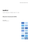
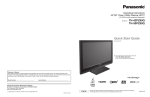
K R A ME R E LE CT R O N IC S L T D .
USER MANUAL
MODEL:
840Hxl
Pattern Generator
P/N: 2900-300032 Rev 2
Contents
1
Introduction
1
2
2.1
Getting Started
Achieving the Best Performance
2
2
3
3.1
Overview
Defining EDID
3
3
4
Defining the 840Hxl Pattern Generator
4
5
5.1
Connecting the 840Hxl
Connecting a PC
6
7
6
6.1
6.2
7
Operating the 840Hxl Pattern Generator
Operating the 840Hxl Using the Front Panel Buttons
Operating the 840Hxl Using the Control Application
Technical Specifications
8
9
10
19
8
Default Communication Parameters
20
9
9.1
9.2
9.3
Serial Protocol
Command Format
Device Response
Commands
21
21
21
22
Figures
Figure 1: 840Hxl Pattern Generator Front Panel
Figure 2: 840Hxl Pattern Generator Rear Panel
Figure 3: Connecting the 840Hxl Pattern Generator
Figure 4: Found New Hardware Wizard Window
Figure 5: File Location Selection Window
Figure 6: Insert Disk Window
Figure 7: Connection Method Window
Figure 8: Connection Error Message
Figure 9: Controller Software Main Window
Figure 10: User Defined Resolution Window
Figure 11: User Defined Resolution Advanced Window
Figure 12: User Defined Resolution Advanced Window–Detailed Timing Descriptor Tab
4
5
6
11
11
12
13
14
14
16
17
18
840Hxl – Contents
i
1
Introduction
Welcome to Kramer Electronics! Since 1981, Kramer Electronics has been
providing a world of unique, creative, and affordable solutions to the vast range of
problems that confront the video, audio, presentation, and broadcasting
professional on a daily basis. In recent years, we have redesigned and upgraded
most of our line, making the best even better!
Our 1,000-plus different models now appear in 11 groups that are clearly defined
by function: GROUP 1: Distribution Amplifiers; GROUP 2: Switchers and Matrix
Switchers; GROUP 3: Control Systems; GROUP 4: Format/Standards Converters;
GROUP 5: Range Extenders and Repeaters; GROUP 6: Specialty AV Products;
GROUP 7: Scan Converters and Scalers; GROUP 8: Cables and Connectors;
GROUP 9: Room Connectivity; GROUP 10: Accessories and Rack Adapters and
GROUP 11: Sierra Products.
Congratulations on purchasing your Kramer MultiTOOLS® 840Hxl Pattern
Generator, which is ideal for the following typical applications:
•
•
As a diagnostic tool in AV setups
Testing and adjusting flat panel LCD displays, projectors, plasmas and
HDMI cables
840Hxl - Introduction
1
2
Getting Started
We recommend that you:
Unpack the equipment carefully and save the original box and packaging
•
materials for possible future shipment
Review the contents of this user manual
•
Use Kramer high performance, high resolution cables
Go to http://www.kramerelectronics.com to check for up-to-date
user manuals, application programs, and to check if firmware
upgrades are available (where appropriate).
i
2.1
Achieving the Best Performance
To achieve the best performance:
•
Use only good quality connection cables to avoid interference, deterioration
in signal quality due to poor matching, and elevated noise levels (often
associated with low quality cables)
•
Avoid interference from neighboring electrical appliances that may adversely
influence signal quality
•
Position your Kramer 840Hxl Pattern Generator away from moisture,
excessive sunlight and dust
i
!
2
Go to http://www.kramerelectronics.com to check for up-to-date
user manuals, application programs, and to check if firmware
upgrades are available (where appropriate).
Caution:
No operator serviceable parts inside the unit
Warning:
Use only the Kramer Electronics input power wall
adapter that is provided with the unit
Warning:
Disconnect the power and unplug the unit from the
wall before installing
840Hxl - Getting Started
3
Overview
The 840Hxl is a high performance HDMI video test pattern generator. It can
generate 32 preset patterns (including several unique patterns incorporating
motion) at 42 popular, predefined computer and HD video resolutions.
In particular, the MultiTOOLS® 840Hxl features:
3.1
•
An HDMI output
•
Five dual-function and two single-function control buttons
•
A two-digit 7 segment display
•
An onboard EPROM that saves the last settings
Defining EDID
The Extended Display Identification Data (EDID) is a data-structure provided by a
display, to describe its capabilities to a graphics card (that is connected to the
display’s source). The EDID enables the 840Hxl to “know” what kind of monitor is
connected to the output. The EDID includes the manufacturer’s name, the product
type, the timing data supported by the display, the display size, luminance data
and (for digital displays only) the pixel mapping data.
EDID is defined by a standard published by the Video Electronics Standards
Association (VESA).
840Hxl - Overview
3
4
Defining the 840Hxl Pattern Generator
Figure 1 defines the front panel of the 840Hxl.
Figure 1: 840Hxl Pattern Generator Front Panel
#
1
Feature
2
FUNCTION
Buttons
3
ON/OFF
RES/HDCP
Function
Press to toggle on and off. Button LED lights when on.
When on, the top row of functions are enabled (RES, PAT, CS and
H/D). When off, the bottom row of functions (HDCP, DC, ASF and
ASD) are enabled (see Section 6.1)
Press to select either the Resolution or HDCP functions
PAT/DC
Press to select either the Pattern or Color Depth functions
4
CS/ASF
Press to select either the Color Space or Audio Sample Frequency
functions
5
H/D / ASD
Press to select either the HDCP/DVI or Audio Sample Depth
functions
6
2-digit 7-segment Display
Indicates the current setting. The display flashes if there is a
problem communicating with the display, for example, if the display
does not support HDCP or does not support the selected resolution
7
ON LED
Lights red when the device receives power
8
– Button
Press to step down through the list of available values
9
+ Button
Press to step up through the list of available values
4
840Hxl - Defining the 840Hxl Pattern Generator
Figure 2 defines the rear panel of the 840Hxl.
Figure 2: 840Hxl Pattern Generator Rear Panel
#
Feature
Function
10
HDMI OUT Connector
Connect to the HDMI acceptor
11
RS-232 9-pin D-sub
Connector
Connect to the serial port on a PC for remote control (see
Section 5.1.1)
12
USB Connector
Connect to the USB port on a PC for remote control
13
5V DC Connector
Connect to the power adapter
840Hxl - Defining the 840Hxl Pattern Generator
5
5
Connecting the 840Hxl
!
Always switch off the power to any device before connecting it to your
840Hxl. After connecting your 840Hxl, connect its power and then
switch on the power to the device.
To connect the 840Hxl as illustrated in the example in Figure 3:
1. Connect the HDMI OUT connector to an HDMI acceptor (for example, a flat
panel LCD display).
2. Optional—connect a PC to control the 840Hxl via the RS-232 or USB ports.
3. Connect the power adapter to the 5V DC socket and to the mains electricity
(not shown in Figure 3).
Note: The device must be connected to the 5V supply or it will not function
correctly. If connected to a PC via the USB the device might appear to work
but it will not function correctly.
Figure 3: Connecting the 840Hxl Pattern Generator
6
840Hxl - Connecting the 840Hxl
5.1
Connecting a PC
5.1.1
Connecting a PC via the RS-232 Serial Port
You can connect to the 840Hxl via an RS-232 connection using, for example, a
PC. Note that a null-modem adapter/connection is not required.
To connect to the product via RS-232:
•
Connect the RS-232 9-pin D-sub rear panel port on the product unit via a
9-wire straight cable (only pin 2 to pin 2, pin 3 to pin 3, and pin 5 to pin 5
need to be connected) to the RS-232 9-pin D-sub port on your PC
5.1.2
Connecting a PC via the USB Port
To connect the 840Hxl via a USB port:
1. Using a USB cable, connect the 840Hxl to a USB port on the PC.
2. Install the USB driver as described in Section 6.2.1.
840Hxl - Connecting the 840Hxl
7
6
Operating the 840Hxl Pattern Generator
The 840Hxl can be operated either using the front panel buttons (see Section 6.1)
or using the 840Hxl Control Application (see Section 6.2).
The 840Hxl Control Application is available as a free download from
http://www.kramerelectronics.com).
The following resolutions are supported.
#
Resolution
#
Resolution
1
VGA 640 x 480 @60Hz
24
1440 x 576i @50Hz
2
720 x 480 @60Hz
25
1280 x 720 @50Hz
3
SVGA 800 x 600 @60Hz
26
1280 x 720 @60Hz
4
XGA 1024 x 768 @60Hz
27
1280 x 720 @100Hz
5
1280 x 720 @60Hz
28
1280 x 720 @120Hz
6
1360 x 768 @60Hz
29
1440 x 288 @50Hz
7
1440 x 900 @60Hz
30
1440 x 480 @60Hz
8
SXGA+ 1400 x 1050 @60Hz
31
2880 x 240 @60Hz
9
SXGA 1280 x 1024 @60Hz
32
2880 x 288 @50Hz
10
WSXGA+ 1680 x 1050 @60Hz
33
2880 x 480 @60Hz
11
SXGA 1280 x 1024 @75Hz
34
2880 x 480i @60Hz
12
HD 1080 1920 x 1080 @60Hz
35
2880 x 576 @50Hz
13
WUXGA 1920 x 1200 @60Hz
36
2880 x 576i @50Hz
14
UXGA 1600 x 1200 @60Hz
37
1920 x 1080 @25Hz
15
720 x 480i @60Hz
38
1920 x 1080 @30Hz
16
HD 1080 1920 x 1080i @60Hz
39
1920 x 1080 @50Hz
17
Output native resolution
40
1920 x 1080i @50Hz
18
720 x 480 @120Hz
41
1920 x 1080 @60Hz
19
720 x 480 @240Hz
42
1920 x 1080i @60Hz
20
720 x 576 @50Hz
43
1920 x 1080i @100Hz
21
720 x 576 @100Hz
44
1920 x 1080i @120Hz
22
720 x 576 @200Hz
45
2K 2048 x 1080 @50Hz
23
1440 x 576 @50Hz
46
2K 2048 x 1080 @60Hz
The following patterns are supported.
8
#
Pattern
#
Pattern
1
100% Color bar
17
Square
2
75% Color bar
18
White dot
3
Gray bar
19
Alternate pixels
4
Red screen
20
White HScroll
5
Green screen
21
White VScroll
6
Blue screen
22
Multiburst
7
Yellow screen
23
Vertical split
8
Cyan screen
24
Horizontal split
840Hxl - Operating the 840Hxl Pattern Generator
#
Pattern
#
Pattern
9
Magenta screen
25
Red ramp
10
Gray screen
26
Green ramp
11
White screen
27
Blue ramp
12
RGB ramp
28
Bounce
13
Black screen
29
Window
14
Crosshatch black
30
White border
15
Crosshatch green
31
Target circle
16
Crosshatch blue
32
Moving ball
The output options in the following table are supported.
6.1
Parameter
Front Panel
Values
Signal Mode
H/D
HDMI (video, audio and data packet), DVI
(video only), Auto
HDCP
HDCP
On, Off
Color Space
CS
RGB, YUV 444, YUV 422, Auto
Color Depth
DC
24 bit, 30 bit, 36 bit, Auto
Audio Sample
Rate
ASF
44kHz, 48kHz, 88kHz, 96kHz, 176kHz,
192kHz, Auto
Audio Sample
Depth
ASD
16 bit, 20 bit, 24 bit, Auto
Operating the 840Hxl Using the Front Panel Buttons
To activate the top row of functions (RES, PAT, CS and H/D):
•
Press the Function ON/OFF button (the button LED lights)
To activate the bottom row of functions (HDCP, DC, ASF and ASD):
•
Press the Function ON/OFF button again (the button LED no longer lights).
To select a function and modify the value, for example, to select a specific
pattern:
1. Press the Function button.
The button lights to indicate the top row of functions (ON) is active.
2. Press the PAT/DC button.
The button lights to indicate that the Pattern function is active.
840Hxl - Operating the 840Hxl Pattern Generator
9
3. Press the + or – button to cycle through the list of available patterns until the
required pattern is displayed on the 7-segment display.
Note: The display flashes if there is a problem communicating with the display, for
example, if the display does not support HDCP or does not support the selected
resolution.
6.2
Operating the 840Hxl Using the Control Application
The 840Hxl Control Application is a PC-based program which lets you program
and control the device.
To use the 840Hxl Control Application you must download and install the USB
driver and the 840Hxl Control Application.
6.2.1
Downloading and Installing the USB Driver and Control Application
Note: The driver only works on 32-bit systems.
To install the USB driver and Control Application:
1. Navigate to the Kramer Electronics Web site
(http://www.kramerelectronics.com) and search for the product 840Hxl.
2. Click on the Downloads tab.
3. Download the 840Hxl Windows USB Driver.
4. Download the 840Hxl Control Application to a designated folder on your
computer.
5. Extract the compressed USB driver file to your designated folder.
Two files are extracted, a .inf and a .sys file.
6. Connect the USB cable between your computer and the 840Hxl.
7. Connect the power supply to the 840Hxl.
8. After a few seconds the Found New Hardware message appears as shown
in Figure 4.
10
840Hxl - Operating the 840Hxl Pattern Generator
Figure 4: Found New Hardware Wizard Window
9. Click on the No, not this time option button.
10. Click Next.
11. Select Install from a list or specific location (Advanced) as shown in
Figure 5.
Figure 5: File Location Selection Window
840Hxl - Operating the 840Hxl Pattern Generator
11
12. Click Next.
13. Select Search for the best driver in these locations.
14. Check Include this location in the search. Browse to your previously
designated folder.
15. Click Next.
16. Select the file atm6124.inf
17. The warning This driver is not digitally signed! appears.
18. Click Next.
19. Ignore the warning. Click Continue Anyway.
20. In the Insert disk window, click OK as shown in Figure 6.
Figure 6: Insert Disk Window
21. Select the file atm6124.sys and click Open.
The driver installs and a success message is displayed. The USB driver has
been successfully installed and you can install the 840Hxl Control
Application.
22. Navigate to the designated folder to which you downloaded the Control
Application.
23. Double-click the file setup.exe from this folder or from the distribution media
included with the 840Hxl.
The Control Application has been successfully installed.
12
840Hxl - Operating the 840Hxl Pattern Generator
6.2.2
Connecting to the Device
To connect to the device:
1. Run the Control Application by clicking Start > Programs > Kramer
Electronics > 840Hxl.
2. Click the Connect button.
The Connection Method window is displayed as shown in Figure 7.
Figure 7: Connection Method Window
3. Select the required connection method (via a serial or USB connection) by
clicking the relevant option button.
4. For a serial connection, select the required Com port from the drop-down
list.
5. For a USB connection, select the required USB device from the drop-down
list.
To view an up-to-date list of available USB ports, press the Refresh Ports
button.
Note: If the drop-down list shows No USB Devices, then either the cable is
faulty/not connected, you have not installed the USB driver (see Section 6.2.1) or
the installation was not successful.
6. Click Connect.
If the connection is not successful, a Timeout error message appears as
shown in Figure 8. If the connection is successful, the main window shown
in Figure 9 appears.
840Hxl - Operating the 840Hxl Pattern Generator
13
Figure 8: Connection Error Message
6.2.3
Controller Software Main Window
The Controller Software Main Window is shown in Figure 9.
Figure 9: Controller Software Main Window
14
840Hxl - Operating the 840Hxl Pattern Generator
#
Feature
Function
1
CONNECT Button
Press to connect to a device (see Section 6.2.2)
2
COMMON Resolutions
Buttons
Press to select a pre-configured output resolution
3
USER DEFINED
Resolutions Buttons
Press to select a pre-configured output resolution
4
User Defined
Resolution Edit Buttons
Press to edit the relevant user defined output resolution
5
Patterns Buttons
Press to select an output pattern
6
Output Settings
Buttons
Press to modify the output settings:
Signal Mode—HDMI, DVI, Auto
HDCP—HDCP, No HDCP
Color Space—RGB, YUV 444, YUV 422, Auto
Color Depth—24 bit, 30 bit, 36 bit, Auto
Audio Sample Rate—44kHz, 48kHz, 88kHz, 96kHz, 176kHz, 192kHz,
Auto
Audio Sample Depth—16 bit, 20 bit, 24 bit, Auto
7
Status of Connected
Display
Information on the currently connected display
8
Status of Output
Information on the currently selected output settings
6.2.4
Editing User Defined Resolutions
To edit a user defined resolution:
1. Click on one of the user defined resolution edit buttons.
The User Defined Resolution Window appears as shown in Figure 10.
840Hxl - Operating the 840Hxl Pattern Generator
15
Figure 10: User Defined Resolution Window
2. In the Label field, enter the required label for the button.
3. Click on one of the More Resolution buttons to select the required
resolution.
4. Click OK to save the resolution settings or click the Advanced button to edit
timing parameters and EDID values.
The Advanced Window appears with the Timing Parameters tab selected
as shown in Figure 11.
16
840Hxl - Operating the 840Hxl Pattern Generator
Figure 11: User Defined Resolution Advanced Window
5. Edit or select the required resolution timing values.
6. Click OK to accept the changes or click on the EDID tab to edit the EDID
values as shown in Figure 12.
840Hxl - Operating the 840Hxl Pattern Generator
17
Figure 12: User Defined Resolution Advanced Window–Detailed Timing Descriptor Tab
7. Edit the detailed timing descriptor values as required.
8. Click OK to save the values.
18
840Hxl - Operating the 840Hxl Pattern Generator
7
Technical Specifications
OUTPUT:
1 HDMI connector
OUTPUT
RESOLUTIONS:
VGA 640 x 480 @60Hz, 720 x 480 @60Hz, SVGA 800 x 600
@60Hz, XGA 1024 x 768 @60Hz, 1280 x 720 @60Hz, 1360 x 768
@60Hz, 1440 x 900 @60Hz, SXGA+ 1400 x 1050 @60Hz, SXGA
1280 x 1024 @60Hz, WSXGA+ 1680 x 1050 @60Hz, SXGA 1280 x
1024 @75Hz, HD 1080 1920 x 1080 @60Hz, WUXGA 1920 x 1200
@60Hz, UXGA 1600 x 1200 @60Hz, 720 x 480i @60Hz, HD 1080
1920 x 1080i @60Hz, Output native resolution, 720 x 480 @120Hz,
720 x 480 @240Hz, 720 x 576 @50Hz, 720 x 576 @100Hz, 720 x
576 @200Hz, 1440 x 576 @50Hz, 1440 x 576i @50Hz,
1280 x 720 @50Hz, 1280 x 720 @60Hz, 1280 x 720 @100Hz,
1280 x 720 @120Hz, 1440 x 288 @50Hz, 1440 x 480 @60Hz,
2880 x 240 @60Hz, 2880 x 288 @50Hz, 2880 x 480 @60Hz, 2880
x 480i @60Hz, 2880 x 576 @50Hz, 2880 x 576i @50Hz, 1920 x
1080 @25Hz, 1920 x 1080 @30Hz, 1920 x 1080 @50Hz, 1920 x
1080i @50Hz, 1920 x 1080 @60Hz, 1920 x 1080i @60Hz, 1920 x
1080i @100Hz, 1920 x 1080i @120Hz, 2K 2048 x 1080 @50Hz,
2K 2048 x 1080 @60Hz
CONTROL:
Five dual-function and two single function front panel buttons,
Remote control via USB or RS-232 on a 9-pin D-sub connector
POWER SOURCE:
5V DC, 460mA
OPERATING
TEMPERATURE:
0° to +55°C (32° to 131°F)
STORAGE
TEMPERATURE:
-45° to +72°C (-49° to 162°F)
HUMIDITY:
10% to 90%, RHL non-condensing
DIMENSIONS:
10.7cm x 10.0cm x 4.4cm (4.2" x 3.9" x 1.7”) W, D, H
WEIGHT:
0.4kg (0.88lbs) approx.
ACCESSORIES:
Power supply
Specifications are subject to change without notice at http://www.kramerelectronics.com
840Hxl - Technical Specifications
19
8
Default Communication Parameters
RS-232
20
Baud Rate:
9600
Data Bits:
8
Stop Bits:
1
Parity:
None
840Hxl - Default Communication Parameters
9
Serial Protocol
The 840Hxl can be controlled via the serial port using the commands described in
this section.
9.1
Command Format
Commands must be in the following format:
0xEB, address, command, length of data, data 1, …data n, checksum
where the following table describes the command components.
Command
Component
0xEB
address
command
length of data
data 1, data n
checksum
9.2
Description
Fixed command start byte
Device address. This is always 0x90 for the 840Hxl
Command to be sent (see Section 9.3)
How many bytes sent/received (from data 1 to data n)
One or more command variables within the range 0x01 to 0xFA and excluding 0xEB
Optional—Checks whether the sending/receiving frame is valid.
Check sum = Address + Command + Data length + Data 1+…+Data n
For example, EBH, 90H, 01H, 01H, F3H, 85H
Check sum = 90H + 01H + 01H + F3H = 185H
Note: The checksum gets the low 8 bits, for example, if the check sum = EBH, then check sum =
14H
Device Response
The device responds as follows:
0xEB, 0x90, command, 0x01, answer, check sum
where answer is one of the values described in the following table.
Command
Component
0xF1
0xF2
0xF3
0xF7
0xFC
Description
Either:
–the device received the wrong address and returns no response
–the device gets information about Errors and Alarms
The data is out of range. The command is not executed
The device is currently controlled by the buttons. The command is not executed
The data length is incorrect. The command is not executed
The data is out of range. The command is not executed
840Hxl - Serial Protocol
21
9.3
Commands
The commands listed below are supported by the 840Hxl.
Note: The checksum is required at the end of the send/receive command as
shown in Section 9.1. If a checksum is not included in a sent command, the device
will not respond.
9.3.1
Get Device Address and Software Version
Command
0x00
Send/Receive
0xEB, 0x00, 0x00, 0x01, 0xXX, checksum
Data
0xXX can be any data except 0xEB
0xEB, [address], 0x00, 0x02, [version], 0x00,
checksum
9.3.2
Set Output Encryption or Decryption
Command
0xE3
Send/Receive
0xEB, 0x00, 0xE3, 0x01, data 1, checksum
0xEB, address, 0xE3, 0x01, 0xFA, checksum
9.3.3
Get Device Status
Command
0xE4
Send/Receive
0xEB, address, 0xE4, 0x01, 0x00, checksum
0xEB, address, 0xE4, 0x08, data1, ....., data8,
checksum
9.3.4
Send/Receive
0xEB, address, 0xE6, 0x02, data1, data2,
checksum
0xEB, address, 0xE6, 0x01, 0xFA,
checksum
22
Data
data1: reserved
data2: reserved
data3: output encryption status:
• 0 = encryption
• 1 = decryption
data4: reserved
data5: reserved
data6: reserved
data7: reserved
data8: reserved
Set Output Status
Command
0xE6
Data
data1:
• 0 = encryption
• 1 = decryption
Data
data 1:
• 0x00: reserved
• 0x01: RESOLUTION_INDEX
• 0x02: PATTERN_INDEX
• 0x03: DEEPCOLOR_MODE
• 0x04: COLORSPACE_MODE
• 0x05:HDMIDVI_INDEX
• 0x06: AUDSAMPLE_INDEX
• 0x07: AUDBIT_INDEX
data 2:
• 0x00 reserved
• from 0x00 to 0x17 (24 resolutions)
• from 0x00 to 0x1f (32 patterns)
• 0 = auto, 0x18 = 24bit, 0x1e = 30bit, 0x24 = 36bit
• 0 = auto, 1 = RGB444, 2 = YUV444, 3 = YUV422
• 0 = auto, 1 = HDMI, 2 = DVI
• 0 = auto, 1 = 44k, 2 = 48k 3 = 88k, 4 = 96k, 5 = 176k, 6 =
192k
• 0 = auto, 0x10 = 16bit, 0x14 = 20bit, 0x18 = 24bit
840Hxl - Serial Protocol
9.3.5
Get Output Status
Command
0xE7
Send/Receive
0xEB, address, 0xE7, 0x01, checksum
0xEB, address, 0xE7, 0x0E, data1,… data14,
checksum
9.3.6
Get Output Status when the Device is in Auto Mode
Command
0xE7
Send/Receive
0xEB, address, 0xE7, 0x01, 0x01, checksum
0xEB, address, 0xE7, 0x08, data1, ……,
data8, checksum
9.3.7
Data (Auto Setup)
Data (Not
Auto Setup)
data1: Deep Color:
0x18 (24bit), 0x1E (30bit), 0x24 (36bit)
Setup value
data2: Color Space:
1 = RGB444, 2 = YUV444,
3 = YUV422
data3: Audio sample:
1 = 44k, 2 = 48k, 3 = 88k, 4 = 96k, 5 =
176k, 6 = 192k
data4: audio bit:
0x10 (16), 0x14 (20), 0x18 (24)
Setup value
Setup value
Setup value
Get Monitor Status
Command
0xE8
Data
Data1: FOLLOWENCRY_MONITOR;
• 0 = decryption
• 1 = encryption
Data2: RESOULTION_INDEX;
• from 0x00 to 0x17 (24 resolutions)
Data3: PATTERN_INDEX;
• from 0x00 to 0x1f (32 patterns)
Data4: DEEPCOLOR_MODE;
• 0 = auto
• 0x18 = 24bit
• 0x1e = 30bit
• 0x24 = 36bit
Data5: COLORSPACE_MODE;
• 0 = auto
• 1 = RGB444
• 2 = YUV444
• 3 = YUV422
Data6: HDMIDVI_INDEX
• 0 = auto
• 1 = HDMI
• 2 = DVI
Data7: AUDSAMPLE_INDEX;
• 0 = auto
• 1 = 44k
• 2 = 48k
• 3 = 88k
• 4 = 96k
• 5 = 176k
• 6 = 192k
Data8: AUDBIT_INDEX;
• 0 = auto
• 0x10 = 16bit
• 0x14 = 20bit
• 0x18 = 24bit
Send/Receive
0xEB, address, 0xE8, 0x01, 0x00, checksum
0xEB, address, 0xE8, 0x08, data1, ……,
data8, checksum
840Hxl - Serial Protocol
Data
data1: reserved
data2: reserved
data3: reserved
data4: monitor type (0 = DVI, 1 = HDMI)
data5: monitor HDCP status. (0 = no HDCP support, 1 =
HDCP supported)
data6: monitor Deep Color status (24/30/36)
data7: Load status. (0 = no HPD, 1=HPD)
data8: reserved
23
9.3.8
Get Monitor Status
Command
0xE9
Send/Receive
0xEB, address, 0xE9, 0x01, 0x00, checksum
0xEB, address, 0xE9, 0x08, data1, ……,
data8, checksum
9.3.9
Data
data1: monitor Color Space status (0 = RGB, 1 = YUV422, 2
= YUV444, 3 = YUV444+422)
data2: reserved
data3: reserved
data4: reserved
data5: reserved
data6: reserved
data7: reserved
data8: reserved
Set Detailed Timing for User-defined Resolution
Command
0xEA
Send/Receive
0xEB, address, 0xEA, 0x26, [block index],
[perform immediately], data1H_4bits,
data1L_4bits, data2H_4bits, data2L_4bits, ……,
data17H_4bits, data17L_4bits, data18H_4bits,
data18L_4bits, checksum
0xEB, address, 0xEA, 0x01, 0xFA, checksum
Data
1. [block index]: From 0 to 7
Note: 7 is the preferred timing of the monitor, so it is
preferable to use 0 to 6
2. [perform immediately]: 1 = switch to the user-defined
resolution immediately, 0 = save the user-defined
resolution but do not switch
3. “H_”: high bits
4. “L_”: low bits
5. “data nH_4bits” and “data nL_4bits”: As, 0xfa apart to
0x0f and 0x0a
6. The 18 data are the detailed timing of the EDID.
Example 1: 1600*1200*60 VESA DMT-10
Frame of Command as: EB 90 EA 26 00 00 04 08 03 0F
04 00 03 00 06 02 0B 00 03 02 04 00 04 00 0C 00 01 03
00 00 06 0F 01 03 01 01 00 00 00 00 01 0E (00)
Example 2: 720p
Frame of Command as: EB 90 EA 26 00 00 00 01 01 0D
00 00 07 02 05 01 0D 00 01 0A 02 00 06 0E 02 08 05 05
00 00 07 0E 08 08 04 02 00 00 00 00 01 0A (00)
9.3.10
Get Detailed Timing for the User-defined Resolution
Command
0xEA
Send/Receive
0xEB, address, 0xEA, 0x01, data1, checksum
Data
data1: From 0 to 7
0xEB, address, 0xEA, 0x26, block index, 00,
data1H_4bits, data1L_4bits, data2H_4bits,
data2L_4bits, ……, data17H_4bits,
data17L_4bits, data18H_4bits, data18L_4bits,
checksum
9.3.11
Setting the Group for Detailed Timing of the User-defined Resolution
Command
0xEA
Send/Receive
0xEB, address, 0xEA, 0x03, data1, data2, data3,
checksum
0xEB, address, 0xEA, 0x01, 0xFA, checksum
24
Data
data1: block index: from 0 to 7
data2: perform immediately: 0 = save the user-defined
resolution but do not switch, 1 = switch to the userdefined resolution immediately
data3: group number, from 0 to 35
840Hxl - Serial Protocol
9.3.12
Get the Monitor EDID
Command
0xFD
9.3.13
Data
[group num]: from 0 to 0x3f. Each group has 8 bytes of
EDID data
0xEB, address, 0xFD, 0x12, 0x03, [group num],
data1H_4bits, data1L_4bits, data2H_4bits,
data2L_4bits, ……, data7H_4bits, data7L_4bits,
data8H_4bits, data8L_4bits, checksum
When sending the command, there are 64 groups for 512
bytes of EDID data
Reset Device
Command
0xED
Send/Receive
0xEB, address, 0xFD, 0x02, 0x03, 0x00,
checksum
Send/Receive
0xEB, address, 0xED, 0x04, 0x03, 0x01, 0x02, 0x07, checksum
0xEB, address, 0xED, 0x01, 0xFA, checksum
840Hxl - Serial Protocol
25
LIMITED WARRANTY
We warrant this product free from defects in material and workmanship under the following terms.
HOW LONG IS THE WARRANTY
Labor and parts are warranted for seven years from the date of the first customer purchase.
WHO IS PROTECTED?
Only the first purchase customer may enforce this warranty.
WHAT IS COVERED AND WHAT IS NOT COVERED
Except as below, this warranty covers all defects in material or workmanship in this product. The following are not
covered by the warranty:
1. Any product which is not distributed by us or which is not purchased from an authorized Kramer dealer. If you are
uncertain as to whether a dealer is authorized, please contact Kramer at one of the agents listed in the Web site
www.kramerelectronics.com.
2. Any product, on which the serial number has been defaced, modified or removed, or on which the WARRANTY VOID
IF TAMPERED sticker has been torn, reattached, removed or otherwise interfered with.
3. Damage, deterioration or malfunction resulting from:
i) Accident, misuse, abuse, neglect, fire, water, lightning or other acts of nature
ii) Product modification, or failure to follow instructions supplied with the product
iii) Repair or attempted repair by anyone not authorized by Kramer
iv) Any shipment of the product (claims must be presented to the carrier)
v) Removal or installation of the product
vi) Any other cause, which does not relate to a product defect
vii) Cartons, equipment enclosures, cables or accessories used in conjunction with the product
WHAT WE WILL PAY FOR AND WHAT WE WILL NOT PAY FOR
We will pay labor and material expenses for covered items. We will not pay for the following:
1. Removal or installations charges.
2. Costs of initial technical adjustments (set-up), including adjustment of user controls or programming. These costs are
the responsibility of the Kramer dealer from whom the product was purchased.
3. Shipping charges.
HOW YOU CAN GET WARRANTY SERVICE
1. To obtain service on you product, you must take or ship it prepaid to any authorized Kramer service center.
2. Whenever warranty service is required, the original dated invoice (or a copy) must be presented as proof of
warranty coverage, and should be included in any shipment of the product. Please also include in any mailing a
contact name, company, address, and a description of the problem(s).
3. For the name of the nearest Kramer authorized service center, consult your authorized dealer.
LIMITATION OF IMPLIED WARRANTIES
All implied warranties, including warranties of merchantability and fitness for a particular purpose, are limited in duration
to the length of this warranty.
EXCLUSION OF DAMAGES
The liability of Kramer for any effective products is limited to the repair or replacement of the product at our option. Kramer
shall not be liable for:
1. Damage to other property caused by defects in this product, damages based upon inconvenience, loss of use of the
product, loss of time, commercial loss; or:
2. Any other damages, whether incidental, consequential or otherwise. Some countries may not allow limitations on
how long an implied warranty lasts and/or do not allow the exclusion or limitation of incidental or consequential
damages, so the above limitations and exclusions may not apply to you.
This warranty gives you specific legal rights, and you may also have other rights, which vary from place to place.
NOTE : All products returned to Kramer for service must have prior approval. This may be obtained from your dealer.
This equipment has been tested to determine compliance with the requirements of:
EN-50081:
EN-50082:
CFR-47:
"Electromagnetic compatibility (EMC);
generic emission standard.
Part 1: Residential, commercial and light industry"
"Electromagnetic compatibility (EMC) generic immunity standard.
Part 1: Residential, commercial and light industry environment".
FCC* Rules and Regulations:
Part 15: “Radio frequency devices
Subpart B Unintentional radiators”
CAUTION!
Servicing the machines can only be done by an authorized Kramer technician. Any user who makes changes or
modifications to the unit without the expressed approval of the manufacturer will void user authority to operate the
equipment.
Use the supplied DC power supply to feed power to the machine.
Please use recommended interconnection cables to connect the machine to other components.
* FCC and CE approved using STP cable (for twisted pair products)
26
840Hxl - Serial Protocol
!
!
PN: 2900- 300032
"
"
Rev: 2