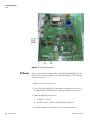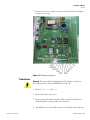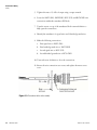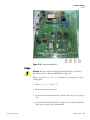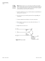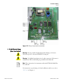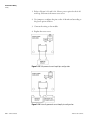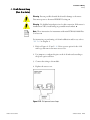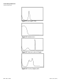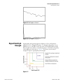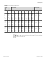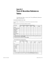
1
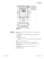
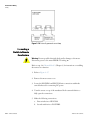
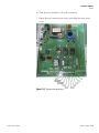
SX40
Dedicated Doppler Flowmeter
User Guide
P/N 1-0563-006
Revision M
Part of Thermo Fisher Scientific
SX40
Dedicated Doppler Flowmeter
User Guide
P/N 1-0563-006
Revision M
© 2010 Thermo Fisher Scientific Inc. All rights reserved.
“Sil-Glyde” is a registered trademark of American Grease Stick Company.
All other trademarks are the property of Thermo Fisher Scientific Inc. and its subsidiaries.
Thermo Fisher Scientific (Thermo Fisher) makes every effort to ensure the accuracy and completeness of this
manual. However, we cannot be responsible for errors, omissions, or any loss of data as the result of errors or
omissions. Thermo Fisher reserves the right to make changes to the manual or improvements to the product at
any time without notice.
The material in this manual is proprietary and cannot be reproduced in any form without expressed written
consent from Thermo Fisher.
This page intentionally left blank.
Contents
Thermo Fisher Scientific
Chapter 1
Product Overview ............................................................................................. 1-1
Introduction........................................................................................ 1-1
Ordering Information ......................................................................... 1-1
Specifications ...................................................................................... 1-2
Performance ..................................................................................... 1-2
Physical ............................................................................................ 1-2
Functional........................................................................................ 1-3
Approvals ......................................................................................... 1-4
Chapter 2
Installation & Wiring........................................................................................ 2-1
Installing the Transducers ................................................................... 2-1
Mounting the Enclosure...................................................................... 2-4
Wiring ................................................................................................ 2-5
AC Power......................................................................................... 2-5
DC Power ........................................................................................ 2-6
Transducers..................................................................................... 2-7
Relays............................................................................................... 2-9
4–20 mA Current Loop (Rev. F or Earlier) .................................... 2-11
4–20 mA Current Loop (Rev. G or Later)...................................... 2-13
Connecting a Switch to Remote Zero Feature ................................ 2-14
Chapter 3
Operation & Configuration .............................................................................. 3-1
The Interface....................................................................................... 3-1
Screen Contrast................................................................................ 3-1
Configuration ..................................................................................... 3-2
Auto Mode....................................................................................... 3-2
Manual Mode .................................................................................. 3-3
HydraScan .......................................................................................... 3-6
Chapter 4
Setup Items......................................................................................................... 4-1
Reset ................................................................................................... 4-1
Config................................................................................................. 4-1
I/O Test .............................................................................................. 4-1
Relays............................................................................................... 4-1
4–20 mA Loop Calibration .............................................................. 4-1
4–20 mA Loop Test ......................................................................... 4-2
Flow.................................................................................................... 4-2
Rate.................................................................................................. 4-2
SX40 User Guide
v
Contents
Max.................................................................................................. 4-2
vi
SX40 User Guide
Chapter 5
Flow Menu Items...............................................................................................5-1
Setup................................................................................................... 5-1
FFT..................................................................................................... 5-1
Logset ................................................................................................. 5-1
Accessing, Saving, & Loading Log Files............................................ 5-1
Trend.................................................................................................. 5-1
Rate.................................................................................................. 5-1
Max.................................................................................................. 5-2
Chapter 6
Troubleshooting & Maintenance ...................................................................6-1
General Troubleshooting .................................................................... 6-1
Learn Mode Warnings ..................................................................... 6-2
Operating Mode Warnings .............................................................. 6-2
Variable Frequency Drives (VFDs)................................................... 6-3
Checking the FFT............................................................................ 6-3
Signal Quality & Strength................................................................... 6-5
Maintenance ....................................................................................... 6-6
General ............................................................................................ 6-6
Replacing the Relays......................................................................... 6-6
Replacing the 4–20 mA Board ......................................................... 6-7
Replacing the Fuse ........................................................................... 6-8
Upgrades............................................................................................. 6-9
Contact Information ........................................................................... 6-9
Warranty........................................................................................... 6-10
Appendix A
Hazardous Area Installations ........................................................................A-1
Appendix B
Obtaining Pipe ID .............................................................................................B-1
Appendix C
Toxic & Hazardous Substances Tables ....................................................... C-1
Thermo Fisher Scientific
Chapter 1
Product Overview
Introduction
Thermo Fisher Scientific’s SX40 dedicated Doppler flowmeter generates
two independent ultrasonic signals at different frequencies. By correlating
these frequencies, the instrument automatically identifies and eliminates
noise errors from sources such as variable frequency drives.
In addition, operation of the instrument is enhanced by an Expert System
that allows the flowmeter to automatically “learn” the application
parameters. As a result, the flowmeter can be easily commissioned in a
fraction of the time required to configure competitive ultrasonic
flowmeters.
Ordering
Information
Thermo Fisher Scientific
Refer to the following list of part numbers to order spare parts for your
instrument.
Table 1–1.
Part Number
Description
22767-0001
Poly CD, specification sheet, meter installation video CD
1-0563-006
User guide
1-0561-005
HydraScan software manual
01008-0006
RS232 cable, standard serial, 6-ft, female to male, DB9
10241-0003
Hazardous area relay, 3 A, SPDT
10261-0013
Fuse, 1 A, time delay, AC input
10396-0194
Power cord connector, CGB, for 6 ft. AC power cord
10605-0001
Pipe strap, SS, 32-inch with 3/8 SS screw
10605-0003
Pipe strap, SS, 67-inch with 3/8 SS screw
10705-0003
Nut driver, 3/8-inch
10808-0002
Coupling compound, silicone RTV108, 2.8 oz.
10823-0005
Coupling compound, Sil-Glyde®, 4 oz.
20192-0001
SS tag
22061-0001
Heater assembly suitable for -40°F to 140°F (-40°C to 60°C) operation,
100–120 Vac
SX40 User Guide
1-1
Product Overview
Specifications
Part Number
Description
22061-0002
Heater assembly suitable for -40°F to 140°F (-40°C to 60°C) operation,
220–240 Vac
22204-0003
Mounting feet, set of 4
22262-0006
PCB assembly, 4–20 mA output (applicable with firmware v. 2.03)
22302-0002
PCB assembly, motherboard (specify input voltage)
22366-0002
Cable adapter, dedicated transducer to portable meter
22490-0001
Cable adapter set, portable transducer to dedicated meter
22511-0020
Intrinsically Safe barrier kit, universal
22686-0002
PCB assembly, Doppler
22703-0002
Transducer assembly (set of 2), 30-ft cable length
22705-0002
PCB assembly, CPU
22714-0002
PCB assembly, adapter board
22732-0001
Front panel assembly, includes keypad and display
22801-0002
PCB assembly, 4–20 mA output (applicable with firmware v. 3.03)
22061-0003
Heater assembly suitable for -40°F to 140°F (-40°C to 60°C) operation,
24 Vdc
Specifications
Performance
Velocity Range: 0.2–18 ft./sec. (0.06–5.5 m/sec.)
Accuracy: ±1% of velocity full scale
Fluids: Liquids containing particulate or entrained gas bubbles
Pipe Size: 0.5–200 in. (12–5000 mm)
Physical
Transmitter: NEMA 4X (IP65), flame retardant, fiberglass reinforced
polyester
Transducers
Two encapsulated dual frequency sensor heads suitable for
submersible/underground service
Encased in stainless steel shrouds, with stainless steel straps and quick
clamps
Cable length: 30 ft. (9 m)
Weight: 12 lb. (5.4 kg)
Dimensions: Refer to Figure 1–1
1-2
SX40 User Guide
Thermo Fisher Scientific
Product Overview
Specifications
Figure 1–1.
Functional
Outputs: 4–20 mA (into 750 ohms), 12-bit, 5 kV opto-isolated; loop or
self-powered
Optional Relay: 5 A, SPDT, programmable relay; maximum of 4
Power Supply
DC Power: 11–28 Vdc
AC Power: 90–132 Vac or 190–250 Vac (switch selectable), 50/60 Hz
Keypad: 19-key with tactile action
Display: Backlit, 240 x 60 dot, high resolution graphics display
Data Logger: 90000 points, programmable in intervals of 30 s, 1, 5, 15,
30, and 60 min
Programming: Via HydraScan software or integral keypad
Serial Interface: RS232
Thermo Fisher Scientific
SX40 User Guide
1-3
Product Overview
Specifications
Temperature Range
Transducers: -40°F to 250°F (-40°C to 121°C); coax cable limited to
176°F (80°C)
Electronics: -20°F to 140°F (-29°C to 60°C)
With integral heater: -40°F to 140°F (-40°C to 60°C)
Approvals
Hazardous Area Certification
Optional: CSA Class I, Div. 2 or Class II, Div. 2
Optional: CSA Intrinsically Safe Class I, Div. 1; Class II, Div. 1; or
Class III, Div. 1
Optional: Intrinsically Safe CENELEC (LCIE)
1-4
SX40 User Guide
Thermo Fisher Scientific
Chapter 2
Installation & Wiring
Installing
stalling the
Transducers
1. Select an installation site:
Keep the following questions in mind when choosing a proper
installation site:
●
Is the chosen section of pipe always full of liquid?
●
Are there at least 5 pipe diameters upstream and 3 pipe diameters
downstream from any directional changes, pipe joints, or
narrowing/widening of the pipe?
Figure 2–1. Recommended installation locations
Conditions at locations A, B, C, D, and E can interfere with the
transmission of the ultrasonic wave and yield inaccurate or unreliable
flow readings:
●
A: Pipe may not be full
●
B: Down flow
●
C: Too close to elbow
●
D: Air collects at the top of the horizontal pipe
●
E: Sediment collects at the bottom of the horizontal pipe
Note Selecting the proper installation location is essential to flow
measurement reliability. Each application is unique and may require a
variation of installation locations. ▲
Thermo Fisher Scientific
SX40 User Guide
2-1
Installation & Wiring
Installing the Transducers
2. Select a transducer orientation:
Refer to Figure 2–2. If your application allows, install the transducers at
the 3 and 9 o’clock locations. Ensure the transducers are parallel to
each other along the pipe circumference.
Figure 2–2. Recommended transducer orientations
3. Attach the transducers to the pipe strap:
a. Use a screwdriver to loosen the mounting screw and slide the lock
back on each transducer.
Figure 2–3.
2-2
SX40 User Guide
Thermo Fisher Scientific
Installation & Wiring
Installing the Transducers
b. Place the pipe strap across the mounting, and slide the lock back
into place.
Figure 2–4.
c. Tighten the screws.
Figure 2–5.
4. Mount the transducers, ensuring the transducers face the same
direction (as shown in Figure 2–6):
a. Wrap the pipe strap around the pipe, and slide the end of the pipe
strap through the tension nut assembly.
b. Pull the strap tightly, and clamp the tension nut down to secure the
strap to the pipe.
c. Loosen the mounting screw of a transducer, and move the
transducer to the 3 o’clock position on the pipe. Tighten the
mounting screw to secure the transducer.
d. Loosen the mounting screw of the second transducer, and move the
transducer to the 9 o’clock position. Tighten the mounting screw
to secure the transducer.
e. Remove the strap from the pipe, and apply sonic coupling
compound to each transducer surface.
f. Reposition the strap on the pipe, placing the transducers in the
proper positions.
Thermo Fisher Scientific
SX40 User Guide
2-3
Installation & Wiring
Mounting the Enclosure
g. Tighten the tension nut assembly with a 3/8-inch hex nut driver to
secure the strap.
Note Increasing the pipe strap tension improves signal transmission. ▲
Figure 2–6.
Mounting
ounting the
Enclosure
Warning To prevent the possibility of electrical shock and/or damage to
the meter, do not mount the enclosure where it can be submerged or
partially submerged. ▲
1. Locate a sturdy, vertical mounting surface.
2. Remove the meter access cover, and locate the 4 mounting holes (1 in
each corner of the cover).
3. Attach the enclosure to the wall using the mounting screws.
4. Replace the meter access cover.
Note An optional mounting ear package is also available. ▲
2-4
SX40 User Guide
Thermo Fisher Scientific
Installation & Wiring
Wiring
Wiring
AC
C Power
Warning Prevent possible electrical shock and/or damage to the meter:
Disconnect power to the meter PRIOR TO wiring. ▲
Caution Connecting AC power to a DC power meter may damage the
meter. ▲
Note CE certifications require that a switch or circuit breaker be installed
in close proximity to the instrument and be labeled as the instrument
disconnect. ▲
Refer to the following instructions and Figure 2–7 when wiring the
instrument for AC power.
1. Remove the meter access cover.
2. Locate the AC input voltage selector, and turn the switch to 110 or 220
V to match the power line voltage.
3. Locate the L1, L2/N, and GND connections within power input block.
4. Turn the terminal screws on top of the input block counterclockwise to
fully open the wire connections.
5. Make the following connections:
a. Ground wire to GND (CE certification requires less than 1 ohm
between terminal and ground)
b. Hot wire to L1
c. If the input voltage is 110 V, neutral wire to L2/N
d. If the input voltage is 220 V, second hot wire to L2/N
6. Turn the terminal screws clockwise to close them connections.
7. Ensure the wires are securely connected to the input block, and replace
the meter access cover.
Thermo Fisher Scientific
SX40 User Guide
2-5
Installation & Wiring
Wiring
Figure 2–7. AC power connections
DC Power
Later versions of the instrument (those with P/N 22302-0002 Rev. G and
later) have DC operation built into the instrument. Refer to the following
instructions and Figure 2–8.
1. Remove the meter access cover.
2. Locate the power input block, and turn the terminal screws on top of
the input block counterclockwise to fully open the wire connections.
3. Make the following connections:
a. +24VDC to P2 +24
b. 24 VDC return to either of the P2 GND connections
4. Turn the terminal screws clockwise to close them connections.
2-6
SX40 User Guide
Thermo Fisher Scientific
Installation & Wiring
Wiring
5. Ensure the wires are securely connected to the input block, and replace
the meter access cover.
Figure 2–8. DC power connections
Transducers
Warning Prevent possible electrical shock and/or damage to the meter:
Disconnect power to the meter PRIOR TO wiring. ▲
1. Refer to Figures 2–9 and 2–10.
2. Remove the meter access cover.
3. Remove the nut from the transducer cable connector, and draw the
cable through the opening in the meter enclosure.
4. Thread the nut onto the cable connector to the inside of the enclosure.
Thermo Fisher Scientific
SX40 User Guide
2-7
Installation & Wiring
Wiring
5. Tighten the nut to 15 ft-lb of torque using a torque wrench.
6. Locate the XMT (DN), XMTGND, RCV (UP), and RCVGND wire
connections within the transducer I/F block.
7. Turn the screws on top of the transducer block counterclockwise to
fully open the connections.
8. Identify the transducer’s 2 signal wires and 2 braided ground wires.
9. Make the following connections:
a. First signal wire to XMT (DN)
b. First braided ground wire to XMT GND
c. Second signal wire to RCV (UP)
d. Second braided ground wire to RCV GND
10. Turn each screw clockwise to close the connections.
11. Ensure the wire connections are secure, and replace the meter access
cover.
Figure 2–9. Transducer cable seal assembly
2-8
SX40 User Guide
Thermo Fisher Scientific
Installation & Wiring
Wiring
Figure 2–10. Transducer connections
Relays
elays
Warning Prevent possible electrical shock and/or damage to the meter:
Disconnect power to the meter PRIOR TO wiring. ▲
Refer to step 10 of “Manual Mode” in Chapter 2 for instructions on relay
configuration.
1. Refer to Figures 2–11 and 2–12.
2. Remove the meter access cover.
3. Locate the 4 relay terminals blocks, and select the relay you are going to
wire.
4. Locate the Normally Closed (NC), Common (C), and Normally Open
(NO) relay contacts on the terminal block.
Thermo Fisher Scientific
SX40 User Guide
2-9
Installation & Wiring
Wiring
Note When the relay is at rest, the circuit is closed between the NC
and C terminals and open between the NO and C terminals. When the
relay is energized, the circuit is open between the NC and C terminals
and closed between the NO and C terminals. ▲
5. Turn the terminal screw on top of each connection counterclockwise to
fully open the connections.
6. Insert the wires for your control system into the corresponding wire
connections.
7. Turn the terminal screws clockwise to close the connections.
8. Ensure the wire connections are secure, and test the relay (see “I/O
Test” in Chapter 4).
9. Replace the meter access cover.
Figure 2–11. Relay schematic
2-10
SX40 User Guide
Thermo Fisher Scientific
Installation & Wiring
Wiring
Figure 2–12. Relays & relay terminal connections
4–20 mA Current Loop
(Rev. F or Earlier)
Warning Prevent possible electrical shock and/or damage to the meter:
Disconnect power to the meter PRIOR TO wiring. ▲
Warning Use shielded twisted pair wires for this connection. If the meter is
installed near VFDs, install wiring in grounded metal conduit. ▲
Note These instructions for instruments with main PCB 22302-0002 Rev.
F or earlier. ▲
For instructions on performing a 4–20 mA calibration and/or test, refer to
“I/O Test” in Chapter 4.
Thermo Fisher Scientific
SX40 User Guide
2-11
Installation & Wiring
Wiring
1. Refer to Figures 2–13 and 2–14. Select a power option for the 4–20
mA loop, and remove the meter access cover.
2. Use jumpers to configure the pins on the 4–20 mA card according to
the power option selection.
3. Connect the wiring to the module.
4. Replace the access cover.
Figure 2–13. Self-powered current loop & pin configuration
Figure 2–14. Externally powered current loop & pin configuration
2-12
SX40 User Guide
Thermo Fisher Scientific
Installation & Wiring
Wiring
4–20 mA Current Loop
(Rev. G or Later)
Warning Prevent possible electrical shock and/or damage to the meter:
Disconnect power to the meter PRIOR TO wiring. ▲
Warning Use shielded twisted pair wires for this connection. If the meter is
installed near VFDs, install wiring in grounded metal conduit. ▲
Note These instructions for instruments with main PCB 22302-0002 Rev.
G or later. ▲
For instructions on performing a 4–20 mA calibration and/or test, refer to
“I/O Test” in Chapter 4.
1. Refer to Figures 2–15 and 2–16. Select a power option for the 4–20
mA loop, and remove the meter access cover.
2. Use jumpers to configure the pins on the 4–20 mA card according to
the power option selection.
3. Connect the wiring to the module.
4. Replace the access cover.
Figure 2–15. Self-powered current loop
Thermo Fisher Scientific
SX40 User Guide
2-13
Installation & Wiring
Wiring
Figure 2–16. Externally powered current loop
Connecting
necting a
Switch to Remote
Zero Feature
Warning Prevent possible electrical shock and/or damage to the meter:
Disconnect power to the meter PRIOR TO wiring. ▲
Refer to step 9 in “Manual Mode” (Chapter 3) for instructions on enabling
the remote zero function.
1. Refer to Figure 2–17.
2. Remove the meter access cover.
3. Locate the POSZERO and RLYCOM wire connections within the
same block used for connecting DC power.
4. Turn the screws on top of the transducer block counterclockwise to
fully open the connections.
5. Make the following connections:
a. First switch wire to RLYCOM
b. Second switch wire to POSZERO
2-14
SX40 User Guide
Thermo Fisher Scientific
Installation & Wiring
Wiring
6. Turn the screws clockwise to close the connections.
7. Ensure the wire connections are secure, and replace the meter access
cover.
Figure 2–17. Remote zero connections
Thermo Fisher Scientific
SX40 User Guide
2-15
This page intentionally left blank.
Chapter 3
Operation & Configuration
The Interface
Figure 3–1. Keypad features
Following is a description of the components called out in Figure 3–1.
Screen Contrast
●
LCD: Displays menu items.
●
Scroll: Press to scroll to the next parameter displayed on the LCD
●
Enter: Press once you have made an entry.
●
Backspace: Deletes the last value entered.
●
Numeric keys: Use to enter values when configuring the meter
●
Menu selection keys: Press to select the corresponding menu item
displayed on the LCD
1. Press the +/- key.
2. When the Adjust Contrast screen appears, press the +/- key again, and
the software scrolls through the levels of contrast. Press the +/- key to
stop the scrolling.
3. Use the scroll and backspace keys to make fine adjustments to the
contrast.
Thermo Fisher Scientific
SX40 User Guide
3-1
Operation & Configuration
Configuration
Configuration
Note the following before configuring the meter:
●
You must know the pipe internal diameter (ID) to ensure reliable flow
measurements. If you do not know the pipe ID, go to Appendix B.
●
There must be flow in the pipe when you start the meter.
There are two modes of operation. Consider using auto mode if your
application is a constant process. The instrument default is the auto mode.
Apply power to the meter, and begin the configuration process by selecting
Auto or Manual operating mode. Once you have completed the
configuration process, you can access these screens from the Flow screen by
selecting Setup > Config.
Auto Mode
1. Pipe ID screen:
a. Enter the pipe ID, and press Enter.
b. Use the scroll key to select the measurement units (inches, mm).
Press Enter to select the unit.
c. Scroll through the available wall material options (carbon steel, cast
iron, concrete liner, stainless steel, copper, plastic), and press Enter
to select.
2. Select Next to move to the next screen. At the Flow Units screen:
d. Use the scroll key to select the flow units (US gallons, million
gallons, cubic meters, oil barrels, Imperial gallons, cubic feet, liters,
liquid barrels), and press Enter.
e.
Use the scroll key to select the time base for flow measurement
(seconds, minutes, hours, days), and press Enter.
3. Select Next to enter learn mode.
4. The meter displays status of the learning process. Refer to “Learn Mode
Warnings” (Table 6–2 in Chapter 6) if you receive one of the following
messages:
3-2
SX40 User Guide
●
Invalid Signal, Can’t Learn
●
No Flow, Can’t Learn
●
Warning Low S Strength
●
Warning Poor S Strength
Thermo Fisher Scientific
Operation & Configuration
Configuration
5. Once the meter completes the learning process, the Flow screen
appears.
a. If the flow reading is not accurate and you can verify the flow from
a calibrated flowmeter or other certified source, perform a
calibration.
b. Refer to “Operating Mode Warnings” (Table 6–3 in Chapter 6) if
the meter displays any of the following warnings:
Manual Mode
●
Warning
●
Alarm
●
Failed/No Flow
1. Pipe ID screen:
a. Enter the pipe ID, and press Enter.
b. Use the scroll key to select the measurement units (inches, mm).
Press Enter to select the unit.
c. Scroll through the available wall material options (carbon steel, cast
iron, concrete liner, stainless steel, copper, plastic), and press Enter
to select.
2. Select Next to move to the next screen. At the Flow Units screen:
a. Use the scroll key to select the flow units (US gallons, million
gallons, cubic meters, oil barrels, Imperial gallons, cubic feet, liters,
liquid barrels), and press Enter.
b.
Use the scroll key to select the time base for flow measurement
(seconds, minutes, hours, days), and press Enter.
3. Select Next to continue, and enter the Maximum Flow Rate.
4. Select Next. At this screen:
a. Scroll through the options available for the Velocity Range (2, 4, 8,
16, 32 ft/s) and press Enter to select. Scroll to the next parameter.
b. Enter a damping coefficient (0–99, 1 unit = 15 s). The damping
coefficient suppresses short term fluctuations in the indicated flow
rate. Increasing the coefficient increases the response time to
changes. Keep damping at a minimum unless the flow rate
fluctuates wildly. In this case, increase damping just enough to
reduce the fluctuation to an acceptable degree. Press Enter, and
scroll to the next parameter.
Thermo Fisher Scientific
SX40 User Guide
3-3
Operation & Configuration
Configuration
Note The Smart Filter used by the meter allows the damping function
to smooth small fluctuations without diminishing the meter’s response
to large flow changes, even when configured with a high damping
coefficient. ▲
c. Select regular or high Transmit Power, and press Enter.
In applications where the signal strength is low, the meter
automatically selects high transmit power. You can manually select
regular or high power in applications where the signal strength is
marginal or where you feel increased or decreased power output
may improve signal quality.
5. At the next screen:
a. Enter the low flow cutoff. Press Enter, and scroll to the next
parameter.
When a zero flow condition occurs, internal sloshing and other
fluid movement can prevent the flowmeter from reading total zero.
This can result in totalizer errors. Minimize these errors by setting a
low flow cutoff which drives the flowmeter to zero for flow rates at
or below specified value.
b. Enter the signal strength cutoff, and press Enter.
6. Select Next to continue. At this screen:
a. Enter the signal quality cutoff, and press Enter.
b. Enter the SNR (signal-to-noise ratio), and press Enter.
7. Select Next. This screen displays flow and velocity readings. You can
also enter a site calibration factor:
a. Determine the flow using another source, and calculate the site
calibration adjustment by dividing the actual flow by the meter
flow.
b. Enter the site calibration adjustment.
8. Select Next. At this screen:
a. Scroll to the required totalizer unit (US gallons, Imperial gallons,
million gallons, cubic feet, cubic meters, liters, oil barrels, liquid
barrels) and press Enter.
b. Scroll through the available scale factors (x 1, 10, 100, 1000,
10000), and press Enter to select.
3-4
SX40 User Guide
Thermo Fisher Scientific
Operation & Configuration
Configuration
c. Determine whether to reset the totalizer and scroll to the
appropriate selection. Press Enter.
9. Select Next. At this screen:
a. To keep relay 1 as the pulse totalizer, scroll to and select x1.
b. To keep relay 4 as the lost power monitor, select Y.
c. To enable the remote zero feature, scroll to On.
The lost power feature is designed to trigger a warning signal (alarm
or warning light) when the meter looses power and is no longer
reading flow. The meter records the number of power losses, and
relay 4 is the dedicated lost power relay. For example, a warning
light in a control room that is powered by an independent source
can indicate when the meter looses power. This feature is ideal for
applications where flowmeter operation is critical.
d. Reset the power monitor by selecting Yes.
10. Select Next. The next four screens enable you to configure the relays.
Determine which relay you want to configure, and move to that screen.
a. Determine the maximum allowable flow. If you want the relay to
energize when flow is greater than maximum acceptable flow, select
On. If the relay should de-energize, select Off.
b. Enter the maximum and minimum allowable flows in the
corresponding text boxes.
c. Activate the relay and press Enter.
11. Select Next to continue. Set the range at this screen:
a. Enter the flow rate that equals the 4 mA (minimum) reading, and
press Enter.
b. Enter the flow rate that equals the 20 mA (maximum) reading, and
press Enter.
12. Select Next, and if a password is required, enter it here.
13. Select Next to move to the final setup screen.
14. Set the time and date at this screen, and press Next to complete the
configuration process.
Thermo Fisher Scientific
SX40 User Guide
3-5
Operation & Configuration
HydraScan
HydraScan
3-6
SX40 User Guide
You can also use the HydraScan software to configure the instrument.
Refer to the HydraScan user guide (P/N 1-0563-005).
Thermo Fisher Scientific
Chapter 4
Setup Items
You can access the Setup menu from the main Flow screen. The Setup
menu displays the instrument version and serial number. It also contains 3
submenus: Reset, Config, and I/O Tst.
Reset
Config
Select this item to reset all configuration parameters to defaults.
Refer to Chapter 3 for details on setting configuration parameters. Each
parameter is discussed in the section “Manual Mode.”
I/O Test
Relays
Access this screen to test the relays. Relays do not have to be configured in
order for you to test them.
Note Exiting this screen returns all relays to the OFF positions. Activate
the relays according to step 10 of “Manual Mode” in Chapter 3. ▲
At the Relay Test screen, scroll to the relay you want to test. Press Enter to
switch the relay on (energize), and press Enter again to switch the relay off
(de-energize).
4–20 mA Loop
Calibration
Note You will need a calibrated current meter to perform this procedure. If
you are using the loop-powered configuration, you will also need a DC
power source. ▲
For wiring instructions, refer to Chapter 2.
1. Set up a calibration current loop.
Thermo Fisher Scientific
SX40 User Guide
4-1
Setup Items
Flow
2. Access the mA Cal screen, and enter the value in mA from the current
meter that corresponds to the zero scale.
3. Press Enter.
4. Enter the value in mA from the current meter that corresponds to the
full scale.
5. Press Enter, and continue to the next section to test the loop.
4–20 mA Loop Test
For wiring instructions, refer to Chapter 2.
Access the mA Tst screen. Use the scroll and backspace keys to move the
current bar. Verify the meter follows the changes. If the meter does not
follow the changes, repeat the calibration.
Flow
Flow menu items are covered in the following chapter.
Trend runs at a real-time rate of action. To view the flow trend, select
Trend from the Flow menu.
Rate
From the Trend screen, select Rate. Scroll through the available rate
options (0.1, 0.5, 1, 5, 15, 60 minutes/reading). Press Enter.
Max
The meter records the maximum flow, date, and time of the maximum
flow since the last reset. You can view this information from the Max
screen.
Reset the data by changing the Max field selection from “Set” to “Clear.”
4-2
SX40 User Guide
Thermo Fisher Scientific
Chapter 5
Flow Menu Items
Setup
FFT
Logset
Setup menu items are covered in the previous chapter.
Refer to “Checking the FFT” in Chapter 6.
To set up the data logging function using the instrument:
1. Select LogSet from the Flow screen.
2. The screen displays the number log points remaining. Select the log
rate (intervals of 0.5, 1, 5, 15, or 60 minutes) and press Enter.
3. Turn the logger on.
4. Select Flow to return to the Flow screen.
Note You cannot select the file in which you want to store a specific log
set. The meter saves the data in sequenced files (0 to 9). The meter
advances to the next file each time the logger is turned on or when a file
logs more than 9000 points. ▲
Accessing, Saving,
& Loading Log Files
Trend
Rate
ate
Thermo Fisher Scientific
You can use HydraScan to download, save, load, and erase log files. Refer
to the HydraScan user manual (1-0563-005).
Trend runs at a real-time rate of action. To view the flow trend, select
Trend from the Flow menu.
From the Trend screen, select Rate. Scroll through the available rate
options (0.1, 0.5, 1, 5, 15, 60 minutes/reading). Press Enter.
SX40 User Guide
5-1
Flow Menu Items
Trend
Max
The meter records the maximum flow, date, and time of the maximum
flow since the last reset. You can view this information from the Max
screen.
Reset the data by changing the Max field selection from “Set” to “Clear.”
5-2
SX40 User Guide
Thermo Fisher Scientific
Chapter 6
Troubleshooting & Maintenance
General
Troubleshooting
The instrument has 4 modes of operation:
●
Setup
●
Learn
●
Operating
●
Manual (used by factory trained personnel primarily for application
troubleshooting)
Use the following table in conjunction with the learn mode and operating
mode warning tables.
Table 6–1. Action codes
Thermo Fisher Scientific
Action
Description
A
1. Turn meter off.
2. Apply more compound.
3. Tighten the pipe strap.
4. Restart the meter to see if warning clears.
B
1. Reposition transducers.
2. See if signal strength increases.
3. See if warning clears.
4. Restart the meter.
C
1. Relocate transducers.
2. See if signal strength increases.
3. See if warning clears.
4. Restart meter.
D
1. Turn meter off, and remove the transducers.
2. Grind the pipe surface if it is rough or coated.
3. Remount the transducers.
4. Restart the meter. See if warning clears.
SX40 User Guide
6-1
Troubleshooting & Maintenance
General Troubleshooting
Learn Mode Warnings
The following table describes the learn mode warnings and appropriate
corrective actions. Complete the corrective actions in the order presented.
Table 6–2. Learn mode warnings & corrective actions
Operating Mode
Warnings
6-2 SX40 User Guide
Warning
Corrective Action
Invalid Signal,
Can’t Learn
1. Refer to Table 6–1 and complete actions A–D, checking the meter after
performing each action to see if the problem was corrected.
2. Contact Thermo Fisher.
No Flow,
Can’t Learn
1. Check for flowing fluid.
2. Make sure the pipe is full.
3. Check connections.
4. Restart meter. See if warning clears.
5. Contact Thermo Fisher.
Warning Low
S Strength
1. Turn meter off.
2. Refer to Table 6–1 and complete actions A–D, checking the meter after
performing each action to see if the problem was corrected.
3. Contact Thermo Fisher.
Warning Poor
S Quality
1. Go into operating mode.
2. Check the FFT.
Table 6–3. Operating mode warnings & corrective actions
Warning
Corrective Action
PQ – Poor
Signal Quality
1. Check the FFT.
2. Refer to Table 6–1 and complete actions B–D, checking the meter after
performing each action to see if the problem was corrected.
3. Contact Thermo Fisher.
FS – Failed
Signal Status
1. Refer to Table 6–1 and complete actions B–D, checking the meter after
performing each action to see if the problem was corrected.
2. Check the FFT.
3. Contact Thermo Fisher.
IS – Invalid
Signal
1. Check the FFT.
2. Contact Thermo Fisher.
Thermo Fisher Scientific
Troubleshooting & Maintenance
General Troubleshooting
Variable Frequency
Drives (VFDs)
Doppler flowmeters are often used in installations which use VFDs. VFDs
can cause significant noise, EMI, and voltage spikes. If there are spikes on
the 4–20 mA signal line while the displayed flow rate is stable, there are
two actions you can take. Both actions may be required in order to resolve
the problem:
1. Disconnect the 4–20 mA loop wiring and connect an ammeter with
short wires directly to the 4–20 mA terminal block. Monitor the meter
to see if the spikes are reduced. Installing a twisted pair shielded loop
wiring in grounded metal conduit may be required.
2. Disconnect power wiring from the meter and connect to an
uninterruptible power supply which is not connected to the facility
wiring. Monitor the 4–20 mA output to see if the spikes are reduced.
Installing the power mains in grounded metal conduit may be required.
Checking the FFT
1. From the Flow screen, select FFT.
2. Refer to Figures 6–1 through 6–6 to determine the FFT condition.
3. Refer to the table below to determine the corrective action.
4. Return to the Flow screen.
Table 6–4.
Thermo Fisher Scientific
FFT Shape
Possible Cause
Corrective Action
Ideal Doppler
N/A
1. Restart the meter.
Broadband noise
Poor pipe coupling or
multiple noise generators
1. Refer to Table 6–1 and complete
action codes A-D, checking the meter
after performing each action to see if
the problem was corrected.
2. Relocate transducers.
3. Turn off source of noise.
Steady noise spike
Electromagnetic noise
1. Turn off source of noise.
2. Relocate transducers.
Fluctuating Doppler
Constantly changing flow
or noise
1. Increase damping (reference
“Configuration” in chapter 3).
2. Relocate transducers.
No Doppler
reflection
I or II
Ultrasound signal not
transmitting
1. Refer to Table 6–1 and complete
action codes A-D, checking the meter
after performing each action to see if
the problem was corrected.
SX40 User Guide 6-3
Troubleshooting & Maintenance
General Troubleshooting
Figure 6–1. Ideal Doppler shape
Figure 6–2. Broadband noise
Figure 6–3. Steady noise spike with Doppler
Figure 6–4. Fluctuating Doppler profile
6-4 SX40 User Guide
Thermo Fisher Scientific
Troubleshooting & Maintenance
Signal Quality & Strength
Figure 6–5. No Doppler reflection I
Figure 6–6. No Doppler reflection II
Signal Quality &
Strength
Signal quality and signal strength are indicators of how well suited an
application is for a Doppler flowmeter. To determine the quality of your
application, go to the Flow screen. Note the %SS and SQ numbers in the
bottom right corner. Refer to the following figure to determine the quality
of the application. Also refer to Table 6–1 for actions you can take to
attempt to improve signal quality and strength.
Figure 6–7.
Thermo Fisher Scientific
SX40 User Guide 6-5
Troubleshooting & Maintenance
Maintenance
Maintenance
General
The instrument is easy to maintain. The transducers and flowmeter are
factory service only components and maintenance free. The following table
describes the instrument components, appropriate maintenance, and a
recommended schedule.
Table 6–5. Suggested maintenance
Component
Maintenance
How Often
Transducers
None: Factory service item
N/A
Coupling compound
Add more compound.
Annually, or whenever:
1. Compound diminishes
2. Repositioning transducers.
3. Relocating meter.
Flowmeter
None: Factory service item.
N/A
Cable connections
Ensure connections are
secure. Remove any buildup
within the connections.
Complete as part of your facility’s
routine maintenance.
Replacing
eplacing the Relays
Warning Prevent possible electrical shock and/or damage to the meter:
Disconnect power to the meter PRIOR TO wiring. ▲
1. Disconnect the power, externally if possible.
2. Remove the meter access cover.
3. Locate the relay sockets (reference Figure 2–11), and remove the relay.
4. Push the replacement relay into the socket until it is secure.
5. Replace the access cover.
6-6 SX40 User Guide
Thermo Fisher Scientific
Troubleshooting & Maintenance
Maintenance
Replacing
placing the 4–20
mA Board
Warning Prevent possible electrical shock and/or damage to the meter:
Disconnect power to the meter PRIOR TO wiring. ▲
1. Remove the meter access cover.
2. Locate the 4–20 mA board (reference Figure 6–8) and disconnect the
wiring to the current loop module.
3. Remove the 2 screws in the lower corners of the module, and lift the
module straight out to prevent damage to the connector on the main
board.
4. Align the pins on the replacement module with the connector on the
main board.
5. Press the module straight in toward the board.
6. Ensure the screw holes in the mounting posts on the main board align
exactly with the screw holes in the module, and replace the screws.
7. Wire and configure the 4–20 mA loop (reference Chapter 2).
8. Reconnect power, and calibrate the current loop according to “4–20
mA Loop Calibration” in Chapter 4.
9. Replace the access cover.
Thermo Fisher Scientific
SX40 User Guide 6-7
Troubleshooting & Maintenance
Maintenance
Figure 6–8. Locations of 4-20 mA board & fuse
Replacing
eplacing the Fuse
Warning Prevent possible electrical shock and/or damage to the meter:
Disconnect power to the meter PRIOR TO wiring. ▲
1. Locate the hole in the meter access cover marked FUSE, or remove the
access cover and locate the fuse holder (shown in Figure 6–8).
2. Use a small, flat blade screwdriver to depress and turn the fuse holder
counterclockwise until the holder pops up.
3. Insert a similar fuse of the same rating (see Figure 6–9).
4. Replace the fuse holder. Depress and turn the holder clockwise until it
locks in place.
5. Replace the access cover if removed.
6-8 SX40 User Guide
Thermo Fisher Scientific
Troubleshooting & Maintenance
Upgrades
Figure 6–9. Fuse access hole label
Upgrades
Contact
Information
The most current software is installed in the instrument prior to shipment.
You can use the RS232 port and a remote terminal to upgrade the software
as newer versions become available. Contact Thermo Fisher to obtain the
most recent versions of the following software:
●
WinLoader (used to upgrade meter software)
●
Meter software
●
HydraScan (data logging software)
The local representative is the first contact for support and is well equipped
to answer questions and provide application assistance. Your representative
also has access to product information and current software revisions. You
can also contact Thermo Fisher directly.
Process Instruments
14 Gormley Industrial Avenue
Gormley, Ontario
L0H 1G0
CANADA
Unit 702-715, 7/F Tower West
Yonghe Plaza No. 28
Andingmen East Street, Beijing
100007 CHINA
+1 (800) 437-7979
+1 (713) 272-0404 direct
+1 (713) 4573 fax
+1 (905) 888-8808
+1 (905) 888-8828 fax
+86 (10) 8419-3588
+86 (10) 8419-3580 fax
A-101, 1CC Trade Tower
Senapati Bapat Road
Pune 411 016
Maharashtra, INDIA
Ion Path, Road Three
Winsford, Cheshire
CW7 3GA
UNITED KINGDOM
1410 Gillingham Lane
Sugar Land, TX
77478 USA
+91 (20) 6626 7000
+91 (20) 6626 7001 fax
+44 (0) 1606 548700
+44 (0) 1606 548711 fax
www.thermoscientific.com
Thermo Fisher Scientific
SX40 User Guide 6-9
Troubleshooting & Maintenance
Warranty
If it becomes necessary to return an instrument:
1. Contact Thermo Fisher for a Return Material Authorization (RMA)
number. You must have the RMA number to return an instrument.
The receiving dock will not accept shipments without the RMA
number.
2. Ensure the instrument is well packed, in its original shipping box if
available.
3. Include a letter fully explaining the symptoms of the failure as well as
detail describing the application where the unit was being operated.
Also include a contact name, phone number, and purchase order
authorizing repairs.
4. Write the RMA number on the outside of the shipping box.
5. Send the unit freight-paid to the address above.
Warranty
Thermo Scientific products are warranted to be free from defects in
material and workmanship at the time of shipment and for one year
thereafter. Any claimed defects in Thermo Scientific products must be
reported within the warranty period. Thermo Fisher shall have the right to
inspect such products at Buyer’s plant or to require Buyer to return such
products to Thermo Fisher plant.
In the event Thermo Fisher requests return of its products, Buyer shall ship
with transportation charges paid by the Buyer to Thermo Fisher plant.
Shipment of repaired or replacement goods from Thermo Fisher plant shall
be F.O.B. Thermo Fisher plant. A quotation of proposed work will be sent
to the customer. Thermo Fisher shall be liable only to replace or repair, at
its option, free of charge, products which are found by Thermo Fisher to be
defective in material or workmanship, and which are reported to Thermo
Fisher within the warranty period as provided above. This right to
replacement shall be Buyer’s exclusive remedy against Thermo Fisher.
Thermo Fisher shall not be liable for labor charges or other losses or
damages of any kind or description, including but not limited to,
incidental, special or consequential damages caused by defective products.
This warranty shall be void if recommendations provided by Thermo
Fisher or its Sales Representatives are not followed concerning methods of
operation, usage and storage or exposure to harsh conditions.
6-10 SX40 User Guide
Thermo Fisher Scientific
Troubleshooting & Maintenance
Warranty
Materials and/or products furnished to Thermo Fisher by other suppliers
shall carry no warranty except such suppliers’ warranties as to materials and
workmanship. Thermo Fisher disclaims all warranties, expressed or
implied, with respect to such products.
EXCEPT AS OTHERWISE AGREED TO IN WRITING BY Thermo
Fisher, THE WARRANTIES GIVEN ABOVE ARE IN LIEU OF ALL
OTHER WARRANTIES, EXPRESSED OR IMPLIED, AND Thermo
Fisher HEREBY DISCLAIMS ALL OTHER WARRANTIES,
INCLUDING THOSE OF MERCHANTABILITY AND FITNESS
FOR PURPOSE.
Thermo Fisher Scientific
SX40 User Guide 6-11
This page intentionally left blank.
Appendix A
Hazardous Area Installations
Figure A–1. Hazardous area installation with barriers
Thermo Fisher Scientific
SX40 User Guide
A-1
Hazardous Area Installations
Figure A–2. Hazardous area installation without barriers
A-2
SX40 User Guide
Thermo Fisher Scientific
Appendix B
Obtaining Pipe ID
If you do not know the pipe ID, try to get pipe OD using one of the
following methods:
●
Read the pipe OD and schedule on the pipe.
●
Read the OD and schedule from system drawings.
●
Use a tape measure to measure the pipe circumference and divide the
measured circumference by 3.14.
●
Use Thermo Fisher’s Ultrasonic pipe Thickness Gauge (P/N
0704/0187), and perform the following calculation:
Pipe ID = Pipe OD – (2 x Pipe Thickness).
Table B–1. Steel, stainless steel, & PVC pipe standard schedules1
Nominal
Pipe
Size
OD
Sch.
5
Sch.
10
(light
wall)
1
1.25
1.5
2
2.5
1.315
1.660
1.900
2.375
2.875
1.185
1.530
1.770
2.245
2.709
1.097
1.442
1.682
2.157
2.635
1.049
1.380
1.610
2.067
2.469
3
3.5
4
5
6
3.500
4.000
4.500
5.563
6.625
3.334
3.834
4.334
5.345
6.407
3.260
3.760
4.260
5.295
6.357
3.068
3.548
4.026
5.047
6.065
8
10
12
14
16
8.625
10.750
12.750
14.000
16.000
8.407
10.482
12.438
15.670
8.329
10.420
12.390
13.500
15.500
8.125
10.250
12.250
13.376
15.376
8.071
10.136
12.090
13.250
15.250
7.981
10.020
11.938
13.124
15.000
7.813
9.750
11.626
12.812
14.688
7.625
9.562
11.374
12.500
14.312
7.437
9.312
11.062
12.124
13.938
7.187
9.062
10.750
11.876
13.562
18
20
24
18.000
20.000
24.000
17.670
19.634
23.564
17.500
19.500
23.500
17.376
19.250
23.250
17.124
19.000
22.876
16.876
18.812
22.624
16.500
18.376
22.062
16.124
17.938
21.562
15.688
17.438
20.938
15.255
17.000
20.376
Thermo Fisher Scientific
Sch.
20
Sch.
30
Sch.
40
Sch.
60
Sch.
80
Sch.
100
Sch.
120
Sch.
140
Sch.
160
Std.
Wall
XSTG
0.957
1.278
1.500
1.939
2.323
0.815
1.160
1.338
1.687
2.125
1.049
1.380
1.610
2.067
2.469
0.957
1.278
1.500
1.939
2.323
2.900
3.364
3.826
4.813
5.761
2.624
3.438
4.313
5.187
3.068
3.548
4.026
5.047
6.065
2.900
3.364
3.826
4.813
5.761
7.001
8.750
10.500
11.500
13.124
6.813
8.500
10.126
11.188
12.812
7.981
10.020
12.000
13.250
15.250
7.625
9.750
11.750
13.000
15.000
14.876
16.500
19.876
14.438
16.062
19.312
17.250
19.250
23.250
17.000
19.000
23.000
3.624
4.563
5.501
SX40 User Guide
B-1
Obtaining Pipe ID
1
Nominal
Pipe
Size
OD
Sch.
5
Sch.
10
(light
wall)
Sch.
20
Sch.
30
Sch.
40
30
36
30.000
36.000
29.500
29.376
35.376
29.000
35.000
28.750
34.750
28.500
34.500
42
48
42.000
48.000
41.000
40.750
40.500
47.250
Sch.
60
Sch.
80
Sch.
100
Sch.
120
Sch.
140
31.876
Sch.
160
Std.
Wall
XSTG
31.312
29.250
35.250
29.000
36.000
41.250
47.250
41.000
47.000
All measurements in inches
Table B–2. Cast iron pipe standard classes1
Nom
Pipe
Size
1
Class A
Class B
Class C
Class D
Class E
Class F
Class G
Class H
OD
ID
OD
ID
OD
ID
OD
ID
OD
ID
OD
ID
OD
ID
OD
ID
3
4
6
8
10
3.80
4.80
6.90
9.05
11.10
3.02
3.96
6.02
8.13
10.10
3.96
5.00
7.10
9.05
11.10
3.12
4.10
6.14
8.03
9.96
3.96
5.00
7.10
9.30
11.40
3.06
4.04
6.08
8.18
10.16
3.96
5.00
7.10
9.30
11.40
3.00
3.96
6.00
8.10
10.04
7.22
9.42
11.60
6.06
8.10
10.12
7.22
9.42
11.60
6.00
8.10
10.00
7.38
9.60
11.84
6.08
8.10
10.12
7.38
9.60
11.84
6.00
8.00
10.00
12
14
16
18
20
13.20
15.30
17.40
19.50
21.60
12.12
14.16
16.20
18.22
20.26
13.20
15.30
17.40
19.50
21.60
11.96
13.98
16.00
18.00
20.00
13.50
15.65
17.80
19.92
22.06
12.14
14.17
16.20
18.18
20.22
13.50
15.65
17.80
19.92
22.06
12.00
14.01
16.02
18.00
20.00
13.78
15.98
18.16
20.34
22.54
12.14
14.18
16.20
18.20
20.24
13.78
15.98
18.16
20.34
22.54
12.00
14.00
16.00
18.00
20.00
14.08
16.32
18.54
20.78
23.02
12.14
14.18
16.18
18.22
20.24
14.08
16.32
18.54
20.78
23.02
12.00
14.00
16.00
18.00
20.00
24
30
36
42
48
25.80
31.74
37.96
44.20
50.50
24.28
28.98
35.98
42.00
47.98
25.80
32.00
38.30
44.50
50.80
24.02
29.94
36.00
41.94
47.96
26.32
32.40
38.70
45.10
51.40
24.22
30.00
35.98
42.02
47.98
26.32
32.74
39.16
45.58
51.98
24.00
30.00
36.00
42.02
48.00
26.90
33.10
39.60
24.28
30.00
36.00
26.90
33.46
40.04
24.00
30.00
36.00
27.76
24.26
27.76
24.00
54
60
72
84
56.66
62.80
75.34
87.54
53.96
60.02
72.10
84.10
57.10
63.40
76.00
88.54
57.10
60.06
72.10
84.10
57.80
64.20
76.88
54.00
60.20
72.10
58.40
64.82
53.94
60.06
All measurements in inches
Note For pipes with cement linings, reduce the pipe ID by twice the lining
thickness. Standard and double cement lining thicknesses are listed in the
next table. ▲
B-2
SX40 User Guide
Thermo Fisher Scientific
Obtaining Pipe ID
Table B–3. Ductile iron pipe standard classes1
Nominal
Pipe
Size
Inside Diameter
OD
1
Cement Lining
Class 50
Class 51
Class 52
Class 53
Class 54
Class 55
Class 56
3.40
4.22
6.28
8.39
10.40
12.46
3.34
4.16
6.22
8.33
10.34
12.40
3.28
4.10
6.16
8.27
10.28
12.34
3.22
4.04
6.10
8.21
10.22
12.28
3.16
3.98
6.04
8.15
10.16
12.22
Std.
Thickness
Double
Thickness
0.125
0.250
3
4
6
8
10
12
3.96
4.80
6.90
9.05
11.10
13.20
6.40
8.51
10.52
12.58
3.46
4.28
6.34
8.45
10.46
12.52
14
16
18
20
24
15.30
17.40
19.50
21.60
25.80
14.64
16.72
18.80
20.88
25.04
14.58
16.66
18.74
20.82
24.98
14.52
16.00
18.68
20.76
24.92
14.46
16.54
18.62
20.70
24.86
14.40
16.48
18.56
20.64
24.80
14.34
16.42
18.50
20.58
24.74
14.28
16.36
18.44
20.52
24.68
0.1875
0.375
30
36
42
48
54
32.00
38.30
44.50
50.80
57.10
31.22
37.44
43.56
49.78
55.96
31.14
37.34
43.44
49.64
55.80
31.06
37.06
43.32
49.50
55.64
30.98
37.14
43.20
49.36
55.48
30.90
37.04
43.08
49.22
55.32
30.82
36.94
42.96
49.08
55.16
30.74
36.84
42.84
48.94
55.00
0.250
0.500
All measurements in inches
Note For pipes with cement linings, reduce the pipe ID by twice the lining
thickness listed above. ▲
Thermo Fisher Scientific
SX40 User Guide
B-3
This page intentionally left blank.
Appendix C
Toxic & Hazardous Substances
Tables
The English and Chinese versions of the Toxic and Hazardous Substances
tables are shown below.
Thermo Fisher Scientific
SX40 User Guide
C-1
This page intentionally left blank.
Thermo Fisher Scientific
81 Wyman Street
P.O. Box 9046
Waltham, Massachusetts 02454-9046
United States
www.thermofisher.com