1
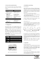
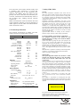
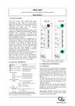
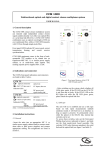
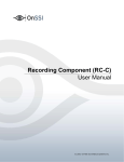
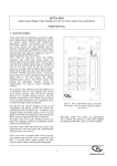
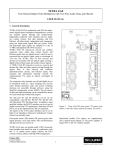
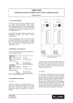
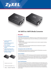
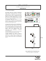
XSNet 1600 MC 10/100Base to 100Base-FX media converter USER MANUAL 1. General description LNK/ACT TX RX LFS FDX/COL 100 FF O FF O FF O FD 0 10 FD FF O N O N O N O D H 10 D H N O The XSNet 1600 Series 10/100 to 100Base-FX Media Converters allow incorporation of a copperbased Ethernet 10/100Base-TX into a fibre-optic 100Base-FX Fast. They use store-and-forward at full wire speed, and are compatible with other 10Base-T & 100Base-TX/FX devices. The 1600 MC connects to two multimode fibres, the 1640 MC uses two single-mode fibres and the 1650 MC needs only one single-mode fibre. In full-duplex mode, this converter can span distances of up to 2 kilometres for multimode fibre and up to 100 kilometres for long-haul single-mode fibre between networking devices. Auto-negotiation (N-Way support), manual half- or full-duplex mode on the fibre port, manual half/fullduplex mode and speed selection on the copper port, Link Fault Signalling (LFS) and both Remote and local loopback Test can be selected via DIP switches. The automatic MDI detection setting feature allows for automatic cable type configuration when establishing a connection between RJ45 ports. Front panel LEDs provide instant information about the device's network and connectivity status. An XSNet 1600 MC series converter, housed in a compact stand-alone box which can also be mounted on a vertical surface, is powered with an 230 VAC/12 VDC adapter, which is included in the package, together with rubber feet and mounting screws. PWR 12 V DC 800 mA 12 50 25 74 Figure 1. Media converter front panel (top), rear panel (middle) and top view with double optical connector (keyed holes are on bottom side). 110 2. Front and rear panel features 4. Installation and testing The front and rear panels of the XSNet 1600 MC feature connectors, LEDs and dip switches as listed in table 1. 4.1. Installation Front panel The converter can be used as a stand-alone box, using the 4 rubber feet included in the package. Alternatively, the two screws included may be used to affix the unit to a vertical, flat surface, fitting the screws’ heads in the two keyholes in the converters bottom side. Feature '100' SC connector(s) TX, RX '10/100' socket (RJ45) optical I/O (FX) transmitter, receiver data I/O, copper side Port status LEDs *FDX (amber) *LNK (green) *ACT (flashing green) *100 (green) *COL (flashing amber) *LFS (red) Rear panel Please observe the following precautions: - do not expose the unit to heat, moisture or dust or similar detrimental influences - keep some free space around the unit for air circulation (there are vents in the sides of the unit). full-duplex mode receiving link pulses data I/O activity transmission at 100 Mbps collision link fault Connect suitable optical and data cabling: CAT3 for 10Base-T and CAT5 for 100BaseTX. Feature Dip switch bank 1-7 auto-negotiation, duplex. loopback, speed Tubular connector 12 VDC 12 DC/800 mA power *PWR (green) DC power OK Table 1. XSNet 1640 MC connectors and indications 4.2. Loopback tests A local loopback test can be performed to check whether the copper side is working and connected correctly; please use dip switch 6. The remote loopback test serves a similar purpose for the fibre segment, using dip switch 7. 3. Configuration Data cable wiring: the auto-MDI function will automatically take care of cable type configuration when connecting the converter to a 10/100Base-TX device. In order to configure duplex modes and speed (with dip switches 2, 3 and 4, see table 2 and figure 2), dip switch 1 (auto-negotiation) must be set to OFF; if not, the media converter will try to adapt automatically. Note: Setting the duplex mode is feasible while the media converter is in operation. Dip switch 1 2 3 4 5 6 7 NWay TX DPX TX SPD FX DPX LFS LLB RLB Fibre Copper Workstation Converter 1 Local Loopback Converter 2 Remote loopback Figure 3. Local and remote loopback For a local test, you will need just one workstation or similar device to set up a copper link to one converter; to perform the remote loopback test, you will need the previous setup together with a second converter having a fibre connection to the first one; see figure 3. Remote and local testing should not be done simultaneously. For normal converter operation, disable both local and remote loopback testing. Function Enables / disables auto-negotiation Copper port (RJ45) full- or half–duplex mode Copper port (RJ45) data rate: 100/10Mbps Fibre port full-duplex (FD) or half-duplex Enables / disables Link Fault Signalling (LFS) Enables / disables Local Loopback (LL BK) Enables / disables Remote Loopback (RLBK) Table 2. 16xx MC dip switch settings 5. Operation 5.1. Normal operation FF O FF O FF O FD 0 10 FD FF O Normal operation will be apparent from the LED patterns described in table 1, with loopback off. If auto-negotiation is not active, please make certain that the duplex mode and speed settings match those of non-adapting devices connected. N O N O N O D H 10 D H N O 5.2. Link fault signalling The LFS LED will immediately light to indicate when a cable has been severed or when some other service disruption has occurred. Figure 2. Dip switch bank layout 2 Four converters can be used to build a primary and a secondary link, connected to a switch that supports Spanning Tree or Fast Spanning Tree protocols. By default, data will travel via the primary link. Once a fault has been detected by the converter, transmission will automatically switch to the secondary link, yielding non-stop network connectivity. Note: The LFS feature works for both the fibre and copper segments. Therefore, in case of disruption in either segment, the LFS LED will indicate that the entire connection is down. 7. Safety, EMC, ESD General The safety information contained in this section, and on other pages of this manual, must be observed whenever this unit is operated, serviced, or repaired. Failure to comply with any precaution, warning, or instruction noted in the manual is in violation of the standards of design, manufacture, and intended use of the unit. Installation, adjustment, maintenance and repair of this equipment are to be performed by trained personnel aware of the hazards involved. For correct and safe use of the equipment and in order to keep the equipment in a safe condition, it is essential that both operating and servicing personnel follow standard safety procedures in addition to the safety precautions and warnings specified in this manual, and that this unit be installed in locations accessible to trained service personnel only. Optelecom-NKF assumes no liability for the customer’s failure to comply with any of these safety requirements. 6. Technical specifications The technical specifications of XSNet 16xx MC media converters are listed in table 3 below. Feature/parameter UL/IEC/EN 60950-1: General safety requirements Value The equipment described in this manual has been designed and tested according to the UL/IEC/EN 60950-1 safety requirements. If there is any doubt regarding the safety of the equipment, do not put it into operation. This might be the case when the equipment shows physical damage or is stressed beyond tolerable limits (e.g. during storage and transportation). Before opening the equipment, disconnect it from all power sources. The equipment must be powered by a SELV*) power supply. When this unit is operated in extremely elevated temperature conditions, it is possible for internal and external metal surfaces to become extremely hot. Optical Wavelengths 1600 MC 1640 MC 1650 MCA TX/RX 1650 MCB TX/RX Fibre type, no. of fibres 1600 MC 1640 MC 1650 MC Max. span (budget) 1600 MC 1640 MC 1640 MC/60 1640 MC/100 1650 MC 1300 1310 1310/1550 1550/1310 nm nm nm nm MM, 2x SM, 2x SM, 1x 2 20 60 100 20 km km km km km Optical safety This optical equipment contains Class 1M lasers or LEDs and has been designed and tested to meet IEC 608251:1993+A1+A2 and IEC 60825-2:2004 safety class 1M requirements. Optical equipment presents potential hazards to testing and servicing personnel owing to high levels of optical radiation. When using magnifying optical instruments, avoid looking directly into the output of an operating transmitter or into the end of a fibre connected to an operating transmitter, or there will be a risk of permanent eye damage. Precautions should be taken to prevent exposure to optical radiation when the unit is removed from its enclosure or when the fiber is disconnected from the unit. The optical radiation is invisible to the eye. Use of controls or adjustments or procedures other than those specified herein may result in hazardous radiation exposure. The installer is responsible for ensuring that the label depicted below (background: yellow; border and text: black) is present in the restricted locations where this equipment is installed. Ethernet Operating standards Operating method Max. distance Cable type IEEE 802.3 IEEE 802.3u store-and-forward 100 UTP Cat 3/4/5 m Environmental Temperature range operating storage Rel. humidity Emissions 0 .. 50 -20 .. 70 5 .. 90 FCC Class A Pt. 15; CE o C C % o Power Voltage and current 12 VDC/800 mA Mechanical Optical connector SC (1600/1640: double) Data connector RJ45 (UTP 100/120 Ω) Dimensions 25 x 74 x 110 mm (hxwxd) (ex. connectors, ex pads) Table 3. XSNet 16xx MC technical specifications Hazard Level 1M The locations of all optical connections are listed in the Indications and Connectors section of this manual. Optical outputs and wavelengths are listed in the Technical Specifications section of this manual. 3 EMC ESD The equipment has been tested and found to meet the CEregulations relating to EMC, and complies with the limits for a Class B device, pursuant to Part 15 of the FCC rules. These limits are designed to provide reasonable protection against interference to radio communications in any installation. The equipment generates, uses and can radiate radio frequency energy; improper use or special circumstances may cause interference to other equipment or a performance decrease due to interference radiated by other equipment. In such cases, the user will have to take appropriate measures to reduce such interactions between this and other equipment. Any interruption of the shielding inside or outside the equipment could cause the equipment to be more prone to fail EMC requirements. Non-video signal lines must use appropriate shielded CAT5 cabling (S-FTP), or at least an equivalent. If system components, such as cabling (e.g. coaxial cable, data/audio/cc wiring) and/or the units, are used outdoors, ensure that all electrically connected components are carefully earthed and protected against surges (high voltage transients caused by switching or lightning). Electrostatic discharge (ESD) can damage or destroy electronic components. Proper precautions should be taken against ESD when opening the equipment. *) SELV: conforming to IEC 60950-1, <60VDC output, output voltage galvanically isolated from mains. All power supplies or power supply cabinets available from Optelecom-NKF comply with these SELV requirements. ©Optelecom-NKF 2006 Version 032805-2 XSNet 1600 MC Mk.II(MW03SP-2) 4