1
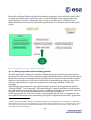
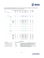
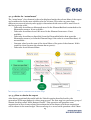
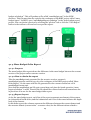
Modeling with VSEE: Definition of Guidelines and Exploitation of the Models YGT Final Report Joël Rey 8/23/2013 Contents 1 Introducing VSD project ...................................................................................................3 1.1 MBSE ...........................................................................................................................3 1.2 VSEE Toolset ...............................................................................................................3 2 Overview of my work .........................................................................................................3 3 Definition of modeling guidelines ................................................................................... 4 3.1 Introduction ............................................................................................................... 4 3.2 Semantics of the different conceptual layers for topological model .......................... 5 3.2.1 Comparing the options ......................................................................................... 5 3.2.2 Big picture ............................................................................................................ 7 3.2.3 Libraries .............................................................................................................. 9 3.2.4 Remaining issues & further developments ........................................................ 10 3.3 3.3.1 Functions and functionalities ........................................................................... 11 3.3.2 Functional network and functional chains ........................................................ 12 3.3.3 Functions and modes ......................................................................................... 13 3.3.4 Relations between modes................................................................................... 15 3.3.5 Operational Activities......................................................................................... 15 3.4 4 Modeling in the functional domain .......................................................................... 11 Allocations traces ...................................................................................................... 16 3.4.1 Allocations and layers of the model ................................................................... 16 3.4.2 Allocation and decomposition ........................................................................... 16 Exploitation of the model ................................................................................................ 18 4.1 Mass budget generator .............................................................................................. 18 4.1.1 Purpose & Philosophy ........................................................................................ 18 4.1.2 Modeling the mass data ..................................................................................... 18 4.1.3 Report ................................................................................................................. 21 4.1.4 Mass Budget Delta Report ................................................................................ 24 4.2 Power budget generator ........................................................................................... 26 4.2.1 Purpose & philosophy ....................................................................................... 26 4.2.2 Modeling the power consumption data ............................................................ 26 4.2.3 Layout of the report............................................................................................ 27 4.2.4 How to obtain the report ................................................................................... 29 4.3 Mode consistency checker ....................................................................................... 29 4.3.1 Purpose and philosophy .................................................................................... 29 1 4.3.2 Rules .................................................................................................................. 29 4.3.3 Examples ........................................................................................................... 30 4.3.4 How to run the check ........................................................................................ 32 Annexe A: Implementation details........................................................................................ 33 SSDE Plugins ..................................................................................................................... 33 Mass Budget Generator .................................................................................................. 33 Power Budget Generator ................................................................................................ 33 Mode consistency checker.............................................................................................. 33 BIRT ................................................................................................................................... 34 Obtaining the data source .............................................................................................. 34 The reports design .......................................................................................................... 34 Delta mass budget report ............................................................................................... 34 ANNEXE B: Step by step modeling guideline....................................................................... 36 Requirements and verification planning ........................................................................... 36 Topological Architecture..................................................................................................... 37 Functional architecture....................................................................................................... 41 Modes ................................................................................................................................. 43 Operational activities ......................................................................................................... 46 Verification .......................................................................................................................... 47 2 1 INTRODUCING VSD PROJECT Virtual Spacecraft Design (VSD) is a project that aims at enabling the Model Based Systems Engineering (MBSE) methodology for space system projects. 1.1 MBSE Model Based Systems Engineering (MBSE) is a recent paradigm in systems engineering that uses computer models to enhance the SE process where the system is described by a set of integrated computer models instead of being described by documents as is the case in classical systems engineering. The benefits of this methodology are: - Traceability along the life cycle - Consistency between the different views of the different disciplines - Easier concurrent collaboration of different actors - Enabling of automated transfer of information from and to domain specific tools. As space systems become increasingly complex, the application of the MBSE methodology in the space industry is seen as necessary to avoid the costs and time to completion to increase significantly. 1.2 VSEE Toolset In the frame of the VSD project, a set of software tools has been produced as prototypes for the deployment of MBSE applied to space systems. The VSEE Toolset is composed of: - SSDE: the model editor - SSVT: a tool for the visualization of the models. - SSRDB: a tool for the management of the repository that supports concurrent work on the datamodel. 2 OVERVIEW OF MY WORK My task was to support the VSD project. It can be divided in three stages. The first stage was to support the acceptance of the VSEE Toolset test all the features and reporting issues. This stage is not described in this report. The second stage was to create a large scale model based on an existing mission1, and to exercise the modeling process and define guidelines on the use of VSEE. This stage is described in chapter 3. The third step was to develop tools for the exploitation of VSEE models, building upon by the previously defined guidelines. This stage is described in chapter 4. 1 The mission used was Sentinel 5p 3 3 DEFINITION OF MODELING GUIDELINES 3.1 Introduction The VSEE framework in its current state offers a lot of freedom for modeling. In the absence of guidelines or constraints on how to use the metamodel, the users have to decide the way they want to use the different classes and relations of the metamodel and have to define their own modeling process. This freedom occurs mostly at two levels: The first one concerns the place of the ValueProperties that hold the engineering data in the model. Since ValueProperties can be attached to most of the classes of the metamodel, the data can be spread among objects of the different aspects of the model such as topological model, functional model and behavioural model. Moreover, the multi-layered architecture of some of the aspects of the model bring another dimension to this freedom. The second level concerns the precise meaning given to the relations between different objects. Some relations have a clear meaning that most users should interpret the same way, but others are more ambiguous and different assumptions can lead to very different ways of modeling and of interpreting a model. Here also the multi-layered architecture ads complexity. Flexibility of the framework and freedom of choosing the way one wants to model are important because the tool must be able to cope with many different kinds of systems and different projects have different needs. However there are also some major drawbacks when too much freedom is given. The first drawback is that it takes time to define one’s own guidelines. Choices regarding the place of property values and the semantics of the relation between objects have consequences that are not easy to foresee when starting the modeling activity. It takes time to establish good guidelines and users will often want to start the modeling at once. It is therefore useful to provide reference guidelines to spare time and offer a smooth introduction to new users to VSEE. A second drawback is that if everybody defines his own modeling practice, it is not possible to exchange models between users without losing or corrupting the meaning behind the data. The third drawback of too much freedom is related to the automation of processes on the model. In order to implement useful features for the exploitation of the models, it must be very clearly defined where each type of data can be found in the model and what the assumptions are regarding the relations between the objects. In order to keep as much freedom and flexibility as possible while countering those drawbacks the idea is to take a modular approach. Different sets of constraints on the model are defined, each enabling some specific feature. The users can then decide if they want to follow the constraints to be able to use the feature, or if they don’t need this feature and prefer to keep some freedom in the way they model. The users also have to think about who they want to be able to exchange models with, in order to adopt the modeling practice of this community. In the following of this chapter, I will present some modeling guidelines that are not related to a specific feature but that are more a way of organizing the model at high level. These modeling guidelines are aimed at obtaining a highly interconnected model that can be navigated in a useful way, and it should serve as a good basis for developing future features. 4 In the next chapter I will present some features that I implemented as examples of how the model can be exploited, together with the constraints on the model required to enable those features. 3.2 Semantics of the different conceptual layers for topological model As said before, the place of the ValueProperties in the model is one of the major aspects that has to be specified in order to enable sharing of the models and automated processes. For example, we need to know where the mass of a component will be stored in the model in order to access it automatically. But in defining those rules, it is important to keep in mind that the model must cope with many variations of the same type of property that represent this property in different contexts along the life cycle of the system. For example a component can have a mass “as specified” by its spec sheets, a mass “as measured” on the physical realization, and mass “as allocated” at the beginning of the project. All those different kinds of mass properties have to coexist in the model, as we want to keep track of this data. To get a good idea on how to organize the data in the model, the first thing to do is to define precisely the semantics attached to the different layers of the topological aspect of the model. Indeed most of the properties related to the components of the system will be stored in the SystemElements that represent them. The question is to know to which layer each property should belong. Having a precise semantics for the topological layers will also allow us to refine the semantics of the relation between the SystemElements of this layer and the other objects of the model. 3.2.1 Comparing the options At the time when I started working on the VSD project, there was no clear consensus on the semantics behind the different layers of the topological aspect of the model. Because of this, it was unclear which ValueProperties should belong to which layer. The main divergence was about the meaning of the ElementDefinition. I did a trade-off analysis on the two different views to measure the impact each view has on the modeling process in order to choose the best option. Here are the two different views of what an ElementDefinition (ED) should be: -‐ View 1: It should define a specific type of elements that share the same specification. A such, the properties and their values are defined in the ED. The ED can be seen as a spec sheet. With such a definition, an ED could represent for example a star tracker of a specific brand and model. -‐ View 2: It should define a generic type of elements that have the same type of properties. The specific values of those properties are left to be defined in the specific context of the usage. With such a definition, an ED could represent a family of star trackers that use the same kind of input and output, have the same operational modes, but that can have different values for their mass and field of view for example. 5 To better understand the full implications of this discussion, let us consider what attributes can be attached to an ElementDefinition. This will give a better idea of what an ElementDefinition can model and what is the most efficient way to use it. An ElementDefinition is composed of: -‐ An internal structure, using element usages and connecting them with interfaces. -‐ External ports (InterfaceEndUsage). -‐ A behavior (DiscreteStateModel) -‐ Values (ValuePropertyValues) for its properties (the propertie s themselves are not contained in the ED) And it can be associated with: -‐ Properties (ValueProperties) -‐ Categories -‐ Functions, for functional allocation -‐ Requirements With all this in mind, here is a comparison of the implications of the two different views: Criterion ED defines a specific kind of components (values of the properties are defined) 1 Internal structure, external interfaces and behavior must be recreated for each ED even if only the value of the properties change. 2 3 4 If two usages of the same ED diverge in the value of their properties during the project, one of them must be retyped with a new ED. Or the diverging properties must be displaced at EU lvl The values of the properties must only be specified once An ED can be used to represent a specification for an element, and catalogues of equipment can be created and then be used to type elements of the users model ED defines a generic kind of components (values of the properties are defined at EU level) A ED can be reused for every element with the same internal structure interface, behavior and kind of properties Nothing must be changed to the model when only values of the properties diverge. The values of the properties must be specified for each usage Such catalogue would have to be based on EUs, that are harder to integrate in the model2. Also, stand-alone EUs are not possible to represent in a diagram and conceptually less clear 2 The user would have to create manually the relation from the containing ElementDefinition to the ElementUsage. Also the ElementUsage could be used only once in the model. 6 The view number 1 wins the comparison because it enables an easier implementation of libraries and catalogues, which is foreseen to be an important element of the framework. The issue with criterion number 1 could be solved by having also a “template” library of ElementDefinitions without values, that could be used to create the refined “equipment catalogue”. 3.2.2 Big picture After the discussion in the previous section, here is a description of the resulting guidelines and an overview of the modeling process. The following explains the correspondence between the different layers of the model and the concepts -‐ -‐ -‐ Category: It defines a set of properties. As such, it can represent a generic type of element that is described by those properties. Categories have an inheritance mechanism that enables the creation of taxonomies of elements. As an example, a category could be used to represent the concept of “star tracker”. This Category would contain all the properties that are needed to describe a star tracker. It could inherit some properties from a more generic Category, such as Sensor. Element Definition: It defines external ports, and internal structure, a behavior, and some properties (either stand-alone ones or as result of category assignement). It can also define the value of its properties. As such, an ElementDefinition represents the spec sheet of a specific component, for example a “star tracker model XYZ from company ABC”. Element Usage: It represents a component in the context of a higher-level assembly, and is typed by and Element Definition which provides the content (properties, behavior, internal structure). For example it could represent the “star tracker model XYZ” in the context of the AOCS subsystem. At this level the component can be interface to the other components of the assembly. The ElementUsage can also be 7 -‐ -‐ used to store properties that are specific to the context in which the component is used, such as its geometrical position in the assembly. ElementOccurrence: It represents a specific occurrence of a component in the context of the whole system. So there is a separate ElementOccurrence for each component of the system, which is not always the case for ElementUsages in case of nested structures. As such, the ElementOccurrence can be seen as a placeholder for an element that needs to be built. As the occurrence tree is folded out, it can be matched to the product tree of CAD tools. ElementRealisation: It represents a physical component that has been produced. For example it could be a “star tracker XYZ with serial number XXXX”. If a physical component needed to be replaced during integration, its ElementRealisation would be detached of the ElementOccurrence, and replaced by an ElementRealisation representing the new component. Here is a big picture view of the modeling process: When building the topological architecture of the model, the user starts by creating some ElementDefinitions and ElementUsages to break down the structure of the system. Those EDs are specific to the project and represent the different sub-systems and modules. When reaching the equipment level, the ElementUsages can be left untyped if the specific type of the equipment is not defined yet, as it is often the case at the beginning of a project. So there could be an ElementUsage “star tracker” without any type in the AOCS ElementDefinition. This EU is a placeholder for a star tracker that will be chosen later. At this stage, the occurrence layer can already be generated. Later on when the type of the star tracker is chosen, the ElementUsage can be typed with an ElementDefinition coming from the “Equipment Library” or provided by a supplier. The occurrence layer can 8 regenerated and if the ElementDefinition of the star tracker defines an internal structure the deeper levels will appear in the explicit product structure. Later on ElementRealisations can be attached to the ElementOccurrences to represent the components that have been produced and to store their measured properties. 3.2.3 Libraries The choice of semantics for the layers for the topological elements enables the convenient implementation of libraries. Libraries will enable reuse of parts of models across different projects. The way those libraries will be created and managed is yet to be defined, but here is a general idea concerning the basic mechanisms. The libraries will be built on several levels, each level using the previous level to build more specific items: 1. The first level is the QUDV model that contains definitions for units and quantity kinds. 2. The second level is a ValueProperty library build using the QUDV model and containing all the recognised types of ValueProperties. Using ValueProperties from this library insures that they can be understood and incorporated into other models. 3. The third level is a Category library that defines a taxonomy of Categories and their contained ValueProperties. This library is itself constructed upon several layers, using the inheritance relation between the Categories. So the library defines categories of elements from very generic like “sensor”, to more specific like “star tracker”. In this example the Category “star tracker” would inherit ValueProperties from the “sensor” Category and add more ValueProperties that are needed to describe a star tracker specifically. 4. The forth level is the Component Tamplate library, that contains ElementDefinitions and their internal structure of ElementUsages, their intefaces and ports, and possibly their behaviour definition. They can also have some Categories assigned to them, but no values associated to their ValueProperties. The ElementDefinitions of this library, together with their attributes, represent families of components that share the same structure, behaviour, and kind of properties, but that have different values for those properties3. 5. Finally comes the Component Library that contains , and that can be seen as a catalogue of spec sheets for component of space systems. This library contains ElementDefinitions and their associated ElementUsages, as well as their ValueProperties with their values. Those ElementDefinitions are ready to be used to type ElementUsages of the users model. 3 Note that in order to use such a library, a mechanism for duplicating ElementDefinitions should be implemented. Indeed if different ElementDefinitions are to be derived from a “template” ElementDefinition, this ElementDefinition needs to be duplicated before being refined in different versions. 9 3.2.4 Remaining issues & further developments 3.2.4.1 Interfaces VSEE offers a complete way to model interfaces and ports, with the ability to give them types. If a list of interface types and related port types is defined, some checks could be implemented to insure the consistency of the connections. VSEE offers also a way to group interfaces to reduce the clustering in the diagrams. However I think this mechanism needs to be refined because at present it can bring some confusion. Indeed, only interfaces can be grouped (using the property “Contained IF”) and not the ports (InterfaceEndUsages). The result is that when creating a port that represents a group of several ports, this relation must be deduced from the fact that it connects with an interface grouping several interfaces. In general elements seem to end up with more ports and interfaces than they really have (because the grouping interfaces and ports are not easily distinguished form the basic ones), which can be confusing. 3.2.4.2 Reference Association Containment relations are unique, as elements can only be contained by one single other element. This produces a single product tree, which is convenient because each element has a precise place. However one might want to describe different logical entities that may contain the same elements. For example a heater for the fuel tank can be part of the propulsion sub-system, but could also be seen as part of the thermal control sub-system. In SysML, there is a mechanism to allow this kind of thing, which is called “reference association”. Unlike containment associations, reference associations are not unique, meaning that an element can have this relation with several other elements. This allows representing overlapping assemblies. The idea is to still have containment relations defining a single product tree, but to also have reference relations to define auxiliary assemblies. I think a similar mechanism would also be useful in VSEE. In the current implementation Categories could be used to “tag” elements as part of some conceptual assembly, and then be able to query for those elements. But this solution is not very intuitive, and it overloads the meaning of Categories. 10 3.3 Modeling in the functional domain Modeling the functional aspect of the system is a less well established activity than modeling the topological or physical aspects. The VSEE framework provides tools for modeling the functional aspect, but the semantics behind the different concepts used an their intended use was at a very primitive stage when I started working on this project. It was part of my work to bring ideas on how to use the concepts present in the framework to create a suitable4 representation of the functional aspect of the model. This task also included identifying concepts or features that were missing in the toolset and that would benefit functional modeling. This part includes therefor both recommendations on how to use the existing features of the toolset and recommendations on how to extend the toolset. 3.3.1 Functions and functionalities Functional modeling is something quite abstract, and the term “function” can be interpreted in various ways. A first step towards structuring functional modeling was to identify two different type of “functions”. The first type of functions appear in the activities called “functional analysis” or “functional decomposition” that are performed at the beginning of a project. Those functions represent “functionalities” that the system must be able to perform, and they are derived from the system specifications. Those functions are typically represented in “functional trees” showing the decomposition of high-level functions into more specific tasks. They can also be represented as lists of activities in some kind of scenario. Even if the typical systems engineering process is supposed to go through functional analysis and decomposition, those activities are not often performed explicitly in space system projects that use a lot of legacy from previous missions or common practice. It is therefore hard to find information relative to these activities and to identify this first type of functions or “functionalities”. For this reason I expect this kind of function will not always be represented in the system model. The second type of functions are the ones that typically appear in the systems documentation and that describe algorithms or procedures. Those functions are much more specific than the first kind because they are implementation oriented, meaning that they describe don’t only describe what is achieved but also how it is achieved using the equipment. At this level the description of how those functions interface with each other is clear enough to model the functional architecture. I propose to allow the system model to contain both types of functions in separate structures. Allocation traces could then be established between those structures to represent how “functionalities” are implemented in “functions”. 3.3.1.1 Modeling functionalities for functional analysis Two different types of diagrams can support modeling of functionalities in VSEE. 4 The meaning of “suitable” here is very subjective. In fact there was no specific target at the beginning. It was rather an exploratory process of trying to see if some useful information could be stored about the functional architecture, provide added value compared to the document based version. 11 The first one is the functional diagram that can be used to represent functional decomposition using FunctionDefinitions and Functions5. Interfaces can be represented although this will probably be represented at a fairly high level. The second is the operational activity diagram, that can be used to represent scenarios or typical procedures, where the functionalities are represent by Activity objects and where their succession can be explicitly shown. Both functional diagrams and operational activity diagrams are also used to represent the more refined functional architecture and operational procedures at later stage of the project. In order to make a distinction between the two usages I suggest to assign a Category called “Functionality” to the Functions and Activities defined during this first phase. This Category does not contain any properties but is just a way to tag those objects for easy distinction later. If allocation traces are to be represented between functionalities and the functions of the functional architecture, new types of traces will need to be made available from FunctionDefinition to FunctionDefinition and from OperationalActivity to FunctionDefinition. This trace could be called “related functionality”. 3.3.1.2 Modeling the functional architecture The functional architecture can be modeled in a functional diagram. It proved quite impractical to try to include the complete functional architecture in a top level function following the approach of the topological architecture. Instead, I decided to represent the interaction of the functions in different contexts. My approach is to represent the dataflow between the functions related to one sub-system or logical entity in a FunctionDefinition that is used as a frame for holding the functional architecture. The contained functions can then be refined in their own FunctionDefinitions. If a function appears in different context it will be typed by the same FunctionDefinition, which results in a centralized reference for this function. When refining functions by defining sub-functions it is important to make a clear distinction between a function that is really part of another one and a function that merely uses or “calls” another one. A function that simply “calls” another one should simply be interface to it and not contain it, otherwise deep nested loops can be created. 3.3.2 Functional network and functional chains Although FunctionOccurrences exist in the meta-model supporting VSEE, there is no feature to generate a functional occurrence layer from the functional definition layer in the current implementation of VSEE6. This is because it was not clear yet how the functional architecture should be modeled and whether or not it is useful to have an occurrence layer. It is true that the concept of occurrence layer is not as obvious as the one of element occurrence in the topological architecture, because functions are disembodied entities. In my opinion a functional occurrence layer can nevertheless be useful to represent the fully connected network of functions that work together in a specific context. With the 5 Note that the class is called Function and not FunctionUsage for some reason I ignore. 6 A related issue is that it is not possible to relate proxy FunctionInterfaceEnds from FunctionDefinitions to the FunctionInterfaceEnds from Functions. Because of this it would not be possible to connect the interfaces properly when generating the functional occurrence layer. 12 support of an occurrence layer, it is possible to differentiate between different contexts in which a function is activated, and to know to which function it gets its inputs from an where its outputs will be used. Such occurrence network can support the concept of “functional chain”. Figure 1: Here is a representation of two function chains as seen in a function occurrence network, representing the function that will contribute to the system outputs represented by the blue and the red dots. Note how the FunctionOccurrence “f2.f1” and “f3.f3” contribute to both outputs A functional chain represents the sequence of the activation of the functions needed to fulfill a specific purpose. For example if we want to obtain one of the system outputs, such a “functional chain” can be built by starting at the desired system output and going backwards, propagating the chain through the interfaces connecting the required inputs of the required functions to the outputs of earlier functions. As some functions require multiple inputs, a “Functional chain” is not a chain per se but is rather composed of parallel threads that converge eventually to one function. If the concept of functional chain is judged to be useful in the model, a new class could be made available to represent the functional chains. This class would reference the FunctionOccurrences taking part in the functional chain. 3.3.3 Functions and modes In VSEE, the behavior of an element is described by a state machine. It is then possible to specify which functions are enabled when the different modes are active. So there is a strong link between the modes of the spacecraft and the functional architecture. Some functions are only available in certain modes, and some functions exist in different versions depending on the mode. In the documentation this can be represented in two ways. Either a functional architecture diagram is provided for each different mode 13 and sub-mode, or there is only one functional architecture diagram where the functions belonging to different modes are represented in different colors. In VSEE, two similar approaches could also be used. In the first approach a different FunctionDefinition is defined for each different mode of a sub-system, and then each mode has an “enable” relation with its respective FunctionDefinition. In the second approach there is only one high level FunctionDefinition per sub-system and it contained the functions for all the modes. Then each mode enables the functions it uses with the “enable” relationship (see figure 2). The first approach has the benefit of having less cluttered functional diagrams. On the other hand there are more function definitions, and it could possibly lead to an explosion in their number depending on the possible combinations of modes. The second approach has the benefit of reducing the redundant modeling work. But the process of defining the “enable” relations between modes and functions can be tedious. Figure 2 Illustration of the two different approaches to represent the link between functional architecture and operational modes 14 3.3.4 Relations between modes In VSEE the behavior of a component is defined by a DiscreteModelDefinition, which is a state machine representation of the way a different mode (represented by the object DiscreteStateDefinition7) can be activated. When the explicit product structure is generated, each occurrence of an element typed by an element definition receives an occurrence of the behavior (DiscreteModelOccurence) containing occurrences of the defined modes (DiscreteStateOccurence). At the occurrence level it is possible to define relations between modes. There are two types of relations between modes: the “forbidden” relation and the “requires” relation. The meaning of the “forbidden” relation is quite straightforward: If mode A forbids mode B, then mode B cannot be active when mode A is active. For the meaning of the “requires” relation, tow interpretations are possible. The first one is that if mode A requires mode B, then mode B must always be active when mode A is active. The second one is that if mode A requires mode B, then mode B must sometimes be active when mode A is active. The difference may seem small but it has a strong impact on the modeling and on the usability of the model. The first interpretation is stronger and lets us use the “requires” relation in a more powerful way when exploiting the model8. On the other hand using this interpretation makes it difficult to model situations where one mode of a sub-system or equipment is used in combination with different modes of another sub-system or component. Indeed in this case the “requires” relation cannot be used and no difference can be made between the modes that are sometimes needed and the modes that are never needed. Despite this drawback I chose to use the first interpretation in order to be able to use stronger inferences in the exploitation features of the model. I assume it is most of the time possible to divide the problematic modes that require several modes alternately into a number of sub-modes that have a single “requires” mode relationship to any other element’s behavior. Projects where this assumption is not valid should find another way of modeling relations between modes. 3.3.5 Operational Activities Operational activities are an aspect of the metamodel on which I didn’t spend much time. The reason is that in my opinion defining semantics for the operational activities first require that the semantics for the functional & behavioral modeling gets consolidated and accepted, which is not yet the case. Also, an ongoing activity called FSS9, which deals with the interfacing of VSEE to a functional engineering simulator, will probably have to address this aspect and set some constraints of its own, which might have a big impact and will need to be taken into account. One thing that is envisioned is that by their capacity to represent sequences of activities and of triggering events for mode transitions, operational activity modeling could support the verification of the consistency of the operational modes design. Also, information about 7 The name DiscreteStateDefinition is a bit confusing because it is used to model operational modes, which is something different from the “state” of the system. The state of the system is not modelled so far. 8 See chapter on Power Budget & Mode Consistency Checks for example 9 Functional System Simulation in Support of Model-‐based System Engineering 15 timing and durations could be modeled, supporting the calculation of time related budgets, such as the energy budget. 3.4 Allocations traces In VSEE, it is possible to model links between different aspects of the model. Those links include allocation of Requirements to other objects of the model from the topological, functional or the operational domain, and allocation of objects of the functional domain to objects of the topological domain. 3.4.1 Allocations and layers of the model The framework allows setting those allocation traces at definition level, usage level and occurrence level. I will here propose how allocation traces between the different layers should be interpreted. If we consider that the final product of the model is the occurrence layer, and that the definition layer is there only to build the occurrence layer in a convenient way, we have to define what is the effect of allocations at the definition layer on the occurrence layer. I propose the following simple rule: -‐ An allocation done at definition level is propagated to all the occurrences typed by this definition. -‐ An allocation done at usage level is propagated to all the occurrences generated by this usage. So if a Requirement is allocated to the ElementDefinition “thruster XYZ” it means that all the ElementOccurrences typed by this ElementDefninition take part in satisfying the requirement. The rules are applicable for both sides of the allocation. For example an allocation between a FunctionDefinition and an ElementDefinition means that every FunctionOccurrence typed by the FunctionDefinition is allocated to all the ElementOccurrences typed by the ElementDefinition. On the other hand an allocation between a FunctionDefinition and an ElementOccurence means that that every FunctionOccurrence typed by the FunctionDefinition is allocated to this same ElementOccurence. 3.4.2 Allocation and decomposition Another thing to consider is that allocations can be done at different levels of the decomposition of the system. For allocations to be traceable across the different hierarchical levels of the system, it is important to define how an allocation to or from an object impacts its contained objects. For example if a Requirement is allocated to an ElemenOccurrence representing a subsystem, does it imply that the ElementOccurrences contained in this sub-system also have an allocation link to this Requirement? Or should each allocation link be traced manually? What about Requirements derived from the initial one. Should it be possible to allocate them to elements outside of the sub-system? A driver in this discussion is the fact that we want to be able to visualize easily the consequences of a change in any component of the spacecraft, be it a topological element, a function or a mode. If an allocation trace exists many levels above the one where the 16 change happens, it can be hard to detect it10. On the other hand it is impractical to trace manually all the allocations as they propagate through deeper layers. Having an automated propagation of the traces would be helpful, but it is hard to define rules that are valid in every situation. A way of making this process easier is to have a similar decomposition for the requirements, the topological architecture and the functional architecture. It is not possible to have a perfect match (otherwise those structure would be somewhat redundant) but it this should be kept in mind when organizing the high level architecture of the system. 10 In the current implementation 17 4 EXPLOITATION OF THE MODEL As explained in the previous chapter, one reason for establishing strict guidelines is that it enables the implementation of automated processes on the datamodel. One part of my work was to provide a few examples of what could be done based on the VSEE framework. Each of those examples demonstrates how different aspects of the meta-model supports the handling and processing of complex information. The VSEE toolset is based on Eclipse and allows for easy integration of plugins for batch operations and dataset checks. I used this feature to create the example exploitation tools. 4.1 Mass budget generator 4.1.1 Purpose & Philosophy The purpose of the Mass Budget Generator for VSEE is to automatically generate a mass budget report in a human readable format. The report is designed to resemble the mass budget found in classic “document based” projects, while adding specific MBSE related information. The main challenge when we want to automatically generate a mass budget report from a VSD model is that the model can contain a lot of different kinds of mass related data. Indeed the fact that the VSD model captures data all along the life cycle of the project means that it has to contain data about the requirements, the design and the verifications, that have all to do with mass but that are conceptually different. The idea is to combine those coexisting data types to e----------------------------nsure the consistency of the mass data across the model when generating the report. 4.1.2 Modeling the mass data 4.1.2.1 Mass properties definitions In order to enable mass budget automatic generation, I had to define a set of ValueProperties in the VSD models representing the different concepts related to the mass of elements of the space system. Here is a list of the concepts: -‐ Allocated Mass : Mass allocated by the system engineer to the element (can be at any containment level). It indicates the maximal mass allowed for the element. It is compulsory for every element of the model to have its allocated mass defined. -‐ Allocation Margin : The portion of the allocated mass of an element that is put aside for coping with uncertainties. It means that this portion is not distributed further down the product tree (if the element is at the bottom of the product tree there is no effect). -‐ Mass as Specified : This is the mass value of the element according to some specification. Typically this value will come from a library of elements. -‐ Mass from CAD : This is the mass value of the element as extracted from a Catia CAD model via the import interface. This mass value is assumed to be the most upto date during the design phase. 18 -‐ -‐ -‐ Mass as Measured : This is the mass of the element according to some measurement. Maturity Level : level of maturity of the element as defined in ECSS-E-HB-10_02A (table 5-1) Margin Policy : This property is defined only once at system level. It is in fact composed of four properties packed together in a category called “System” and it defines the margin that must be applied to each element according to its maturity level. Figure 3: maturity levels 4.1.2.2 Where to store the properties As the VSD models are organized in a multi-layer architecture, I also had to define to which layer each of the mass related concepts should be attached. This was done based on the analysis of the modeling process that is depicted in the next section. Property Allocated Mass Allocation Margin Maturity Level Mass as Specified Contained by ElementOccurrence ElementOccurrence ElementOccurrence ElementDefinition/ ElementUsage Mass from CAD Mass as Measured Margin Policy ElementOccurrence ElementRealisation Top level ElementOccurence, contained by Category “System” 19 Placing the Allocated Mass and Allocation Margin properties at the definition level could also be a possibility (and would ease reuse in case of multiple same components being used). However it seems conceptually less correct to say that mass is allocated to an ElementDefinition because this represents specification of an element and not the actual object. Figure 4: Distribution of the mass properties in the model 4.1.2.3 Mass properties and modeling process The first step in the creation of a model is to define the general architecture based on the product tree of the system. This is done by using ElementDefinitions and ElementUsages to define the successive containment levels of the model. At first, the elements that are at the bottom of the product tree will only be defined by an ElementUsage without a type. This will be a representation of a generic equipment of some type (like Star Tracker for example). After defining the architecture, the explicit product structure can be generated, and the “Allocated Mass”11 (and optionally “Allocation Margin”) must be defined for each element in its ElementOccurrence. The margin policy can also be defined by assigning the “System” category to the top level ElementOccurence and filling the properties. As the project goes on, choices are made concerning the specific type of equipment to be used, and the ElementUsages representing the generic equipment items can be typed with 11 Placing the Allocated Mass and Allocation Margin properties at the definition level could also be a possibility (and would ease reuse in case of multiple same components being used). However it is conceptually less correct to say that mass is allocated to an ElementDefinition because this represents the concept of a type and not an actual object (or planned object). 20 ElementDefinitions that represent the specification of those specific equipment. The ElementDefinitions can come from a reusable library. They can of course increase the depth of the model if they define some lower level parts. Those ElementDefinitions will typically define a “Mass as Specified” value for the element. The Mass as Specified can be overwritten in the ElementUsage for flexibility purpose. When a CAD of the system is available, it can be imported into VSD and mapped to the explicit product structure. This allows extracting some properties of the CAD model, such as the mass value, and store it as “Mass from CAD” property in the ElementOccurrences. When the project enters production and assembly phases, the properties of the physical components will be measured. Those properties can be stored in an ElementRealization attached to the corresponding ElementOccurrence. Among those properties will be the “Mass as Measured”. 4.1.3 Report 4.1.3.1 Layout Each line of the report represents an element of the system, in a hierarchical break down. The indentation and color of the name indicates the depth level of the element. The columns of the report can be thought as being divided in two groups. The first three columns (Alloc Mass, Alloc Margin and Alloc Balance) are related to mass allocation. The Alloc Mass column shows the value of the Allocated Mass property of the element. If the element does not define a value for the Allocated Mass (error), the column will show “-1” and highlight it in fuchsia. The Alloc Margin column shows the value of the Allocation Margin property of the element. If the element does not define a value, the column shows 0. The Alloc Balance column shows how much of the Allocated Mass of the element is left to be shared among its parts. The formula for the allocation balance is “Allocated Mass*(1Allocation Margin) – sum(Allocated Mass of contained elements)”. If the Allocated Mass property is not defined, the column will show 0. If the Balance is negative, meaning that more mass than available has been allocated to the parts of this element, the value will be highlighted in fuchsia. The next four columns are related to the actual mass of the element. The column Mass Type indicates where the actual mass information comes from, i.e which kind of ValueProperty was available. The Maturity Level column shows the value stored in the Maturity Level property of the element. The Mass column shows the actual mass of the element, representing the most reliable mass value available. This value can come from the Mass as Specified, the Mass from CAD, the Mass as Measured or be computed based on the mass of the components of the element (see next section). The auxiliary value on the right of the Mass column shows the value of the sum of the mass of the parts of the element, and can be used to highlight problems when mass properties are stored at different containment levels in the model and are inconsistent. The contingency column shows the mass contingency for the element calculated from the actual mass, the Maturity Level and the corresponding Margin Policy. The Final Balance column shows the difference between the mass allocated to the element and its actual mass. If this value is negative, it will be highlighted in red, and so will be the mass value. If there is a problem with the allocated mass itself, the value will be highlighted in fuchsia. 21 At the bottom of the budget table, a list of textual warnings is displayed that explain the different problems that occurred in the mass budget. Figure 5: Example of a mass budget report 22 4.1.3.2 Rules for “actual mass” The “actual mass” of an element is the value displayed under the column Mass of the report and considered to be the most reliable value for its mass. This value can come from different sources and priority rules apply to determine which source will be used. Here is the list of priority rules: -‐ Take value from Mass as Measured stored in the ElementRealisation attached to the ElementOccurrence. If not available… -‐ Take value from Mass from CAD stored in the Element Occurrence. If not available… -‐ Take value from Mass as Specified, from the ElementDefinition that types the ElementOccurrence (or from the ElementUsage if the value is overwritten there). If not available… -‐ Compute value from the sum of the Actual Mass of the parts of the element. If this cannot be done (because the element has no parts)… -‐ Take value from Allocated Mass. Figure 6: Priority of the mass properties for being selected as "actual mass" during the budget calculation. The way the contingency mass is calculated is also shown in orange. 4.1.3.3 How to obtain the report After having populated the model with the ValueProperties described earlier, the generation of the mass budget is a three step process. The first step is to perform a group of dataset checking called “Mass Dataset Checks”. This operation will generate some annotations in case of mass related inconsistencies in the dataset, and those annotations will be shown in the mass budget. The second step is to run a batch operation called “Mass 23 budget calculation”. This will produce a file called “massBudget.xmi” in the SSDE directory. This file must then be copied to the workspace of the BIRT project called “mass budget report”. In BIRT, open “massBudgetReport.rptdesign” in the “mass budget report” project. You can obtain a preview by selecting the “preview” tab or click the “View Report” button in the toolbar to choose how to export the report. Figure 7: Data flow for the generation of the mass budget. 4.1.4 Mass Budget Delta Report 4.1.4.1 Purpose The mass budget delta report shows the difference in the mass budget between the current version of the project and an ancestor version. 4.1.4.2 How to obtain the report Take the massBudget.xmi generated for the ancestor version, rename it massBudgetAncestor.xmi and copy it to the workspace of the BIRT project called “Mass Delta Report”. Do the same with the file generated for the current version but call it massBudgetCurrent.xmi. Note that the massBudget.xmi file gets overwritten each time the batch operation “mass buget calculation” is used. Therefor the file should be collected and stored somewhere else in prevision of its use for the mass budget delta report. 4.1.4.3 Report Layout As for the mass budget report, each line of the report represents an element of the system, in a hierarchical break down, and the indentation and color of the name indicates the depth level of the element. In this delta report, the columns represent the difference between the current dataset and the ancestor dataset (current value – ancestor value) for the different values related to 24 mass. The explanation about each column can be found in the explanation about the mass budget report. If an element has been deleted or has been created in between the two versions of the datamodel, its name will appear in red or green respectively. 25 4.2 Power budget generator 4.2.1 Purpose & philosophy The purpose of the Power Budget Generator for VSEE is to automatically generate a power budget report in a human readable format. The report is designed to resemble the power budget found in classic “document based” projects. The main challenge when we want to automatically generate a power budget report from a VSD model is that it involves the different modes of each element, and the relation between the modes of the different levels of the model. For this example, I decided to disregard the multi-dimensionality of the data that was taken into account for the mass budget, in order to focus on the specificity of dealing with modes. This means that the power consumption data will only reside at occurrence level, not taking into account the fact that the data could come from a catalogue at definition level. The same mechanism as used for the mass budget generator could be applied straightforward for the power budget too to deal with that matter. 4.2.2 Modeling the power consumption data Since the power consumption of the components can change depending on the operational mode of the component, the best way to store the power consumption data is to attach it to the DicreteStateOccurrence objects themselves instead of attaching it to the ElementOccurrence like was done for the mass. This allows storing the data for each mode separately. We call the ValueProperty “Power Consumption”. We then need to represent in the model which modes of the components are active when a sub-system is in a specific mode. For this, I used the “requires” relation between DiscreteStateOccurrences, with the assumption that each component can only be in one specific mode for each mode of the sub-system (i.e. the mode of the subsystem defines completely the modes of its components). 26 With the data modeled this way, the power budget can simply be calculated for each mode of a sub-system by adding the power consumption of all the component modes required by this sub-system mode. Note that only the required modes belonging to components that are contained in the subsystem are taken into account, although “requires” relation can also be defined with modes of elements that are not contained. 4.2.3 Layout of the report The elements of the system are shown in a hierarchical break down, an each line represents a mode of an element. Note that elements that do not have modes or a power consumption value are omitted. The column named “Power” contains the value of the power consumption of the element in this mode. The column “Englobing modes” lists the modes of the containing elements that require this mode. 27 28 4.2.4 How to obtain the report After having attached the ValueProperty “Power Consuption” to the DicreteStateOccurrences, the generation of the power budget is a two-step process. The first step is to run a batch operation called “Power budget calculation”. This will produce a file called “powerBudget.xmi” in the SSDE directory. This file must then be copied to the workspace of the BIRT project called “power budget report”. In BIRT, open “powerBudgetReport.rptdesign” in the “power budget report” project. You can obtain a preview by selecting the “preview” tab or click the “View Report” button in the toolbar to choose how to export the report. 4.3 Mode consistency checker 4.3.1 Purpose and philosophy The mode consistency checker helps detecting incoherence in the constraints between modes. The idea is that for large systems, an intricate network of relations between modes can exist and that it can be hard to detect operational conflicts, whereas an automated process can do this easily for certain type of conflicts. The tool is composed of two separate elements. The first one, called Mode Constraints Extender, automatically creates constraints between modes by inferences drawn from the existing constraints. The second one, called Mode Constraints Consistency Check, analyses the relations between modes with some simple rules and flags issues. The Mode Constraint Extender has to be used first so that all constraints can be analyzed by the Mode Constraints Consistency Check. 4.3.2 Rules The two types of constraints that can be modeled between DiscreteStateOccurrences has already been described in section 3.4.4. I will now explain how rules are applied on those constraints. 4.3.2.1 Mode Constraints Extender The Mode Constraints Extender follows one rule for creating new “requires” relations, and one rule for creating new “forbids” relations. The two rules are the following: -‐ If mode A requires mode B that requires mode C, than mode A requires mode C. -‐ If mode A requires mode B that forbids mode C, than mode A forbids mode C, and mode C forbids mode A12. 12 The way we define the “forbids” relation causes it to be always bi-‐directional 29 The constraint relations created with the Mode Constraints Extender are automatically assigned with the Category “automaticallyGeneratedItem”. The purpose is to differentiate them form the user defined constraints, and to be able to erase them all if desired. 4.3.2.2 Mode Constraints Consistency Checker The Mode Constraints Consistency Checker detects two kinds of conflicts, following those two rules: -‐ A mode cannot require a mode and forbid (or be forbidden by) this same mode at the same time. -‐ A mode cannot require more than one mode belonging to the same element. Those situations are not likely to be modeled directly but can appear after the Mode Constraints Extender has been used to generate all the implied relations. Mode constraints that are in conflict are annotated accordingly. 4.3.3 Examples Here are two examples of simple inconsistent situations that can be detected. 30 Figure 8: Mode 2 of element A ends up requiring both modes of element C, which is not allowed. Figure 9: Mode 2 of element A ends up requiring and forbidding mode 2 of element D, which is not allowed. 31 4.3.4 How to run the check First the batch operation “required modes extender” must be executed. This will potentially create new DiscreteStateOccConstraints, which will be labeled with the Category “AutomaticallyGeneratedItem”. Then the batch operation “mode constraints consistency checker” can be executed, and will potentially create some annotations attached to some DiscreteStateOccConstraints. Those annotations can be found by going to the Annotation Editor, selecting the Check-Annotation tab and filtering the result to show types RequiedState or ForbiddenState. 32 ANNEX A: IMPLEMENTATION DETAILS SSDE Plugins Plugins have to be added to the “plugins” folder of SSDE, and then edit the 'bundles.info' file in SSDE's 'configuration/org.eclipse.equinox.simpleconfigurator' folder as described in SSDE’s user manual. Mass Budget Generator The mass budget generator uses two plugins. The first one is “rey.massBudgetBatchOperation_1.0.0.jar”, which is the batch operation that produces the massModel.xmi file as well as some annotations13 on the elements in case of inconsistencies. This file is based on a simple EMF model for the representation of elements of the budget, which correspond to ElementOccurrences in the explicit product structure. Those budget elements gather the information about the allocated mass, the actual mass, the maturity level, and their position in the product tree by indicating their containment hierarchy in the “Level X” fields. The EMF model also has objects for representing the margin policy and the mass related annotations. The second one is “rey.datasetchecker.massDatasetChecks_1.0.0.jar”, which is a dataset check which does some additional consistency checking (things that could not conveniently be integrated to the batch operation) and annotates the elements in case of inconsistencies. Power Budget Generator The plugin used for the power budget report is “rey.powerBudgetBatchOperation_1.0.0.jar”. It produces a file called “powerBudget.xmi” which is based on a simple EMF model for the representation of elements of the budget. There is one such element for each DiscreteStateOccurrence carrying the “Power Consumption” ValueProperty. Those elements carry the information of the power consumption, about which higher level mode requires them, and of their position in the product tree by indicating their containment hierarchy in the “Level X” fields. Mode consistency checker The mode consistency checker uses the two plugins “rey.modes.requiredModesExtender_1.0.0.jar” and “rey.modes.modeConstraintsConsistencyCheck_1.0.0.jar”. 13 Note that batch operations don’t usually produce check annotations. However I decided to add this manually to the batch operation because those checks take advantage of the processing done during the mass budget generation. 33 BIRT Obtaining the data source BIRT an eclipse based reporting tool. It accepts many different format of data sources as input an can generate reports in many formats. BIRT can read EMF (Eclipse Modeling Framework) models using a EMF to ODA (Open Data Access) driver14. For using EMF models, the corresponding EMF metamodel must be registered in Eclipse. This is done by gathering in a feature the three plugins (model code, edit code and editor code) generated from the model by EMF, and then installing the feature in Eclipse by going to the “help” menu and choosing “install new software”. In the new window press the “Add” button, and then press “Archive” and select the archive file containing the feature to be installed. If you then untick the “group item by category” option, the feature will appear in the list. Select it and press next to install it. The file “massBudget.xmi” generated by the Mass Budget Generator is in a EMF format, and the feature “mass_budget_model_feature.zip” must be installed in Eclipse to enable BIRT to read it. The file “powerBudget.xmi” generated by the Mass Budget Generator is in a EMF format, and the feature “power_budget_model_feature.zip” must be installed in Eclipse to enable BIRT to read it. The reports design BIRT has interesting features for creating listings with some grouping in categories. However it does not support well the representation of containment hierarchies such as a product tree. In order to create such structure, I had to use a workaround. I created in BIRT a series of joint data sets so that each element of the final data set also contains the data related to its containing elements. The elements are then grouped according to their “levels” properties to create the breakdown. The elements that are not at the deeper level need to be filtered out because we don’t want them to create a separate entry in the table. What we want is to display their data on the line where the corresponding group headline is (the name of the group being the name of the containing element). As the data corresponding to the containing element is available is all its contained elements, the first element of the group provides the data so that it can be displayed at the headline level. If an element is not at the deepest level but does not contain any further parts, it is not filtered out because the entry has to be created. However the entry is “highlighted” in white so that only the headline appears, avoiding the redundancy. Delta mass budget report For the Delta Mass Budget report, the current and ancestor datasets are joined based on the unique ID of the elements. If an element has been deleted or created in the current dataset, it will be detected by noticing that the data relative to the current or ancestor dataset are empty in the new joint dataset, and this is highlighted in the report. 14 This driver has to be installed in Eclipse by going to “help” -‐> Install new software, then selecting “Juno -‐ http://download.eclipse.org/releases/juno” in the “work with” field, and the going to the “Modeling section”. 34 Special “computed columns” had to be created in order to access the right data if the element is missing in one of the datasets. Those columns simply take the non-empty value from either the ancestor or current dataset. Then using those columns new or deleted elements can be treated as the other elements. 35 ANNEX B: STEP BY STEP MODELING GUIDELINE This is a step-by-step guideline to creating a model of a space system using the Space System Design Editor (SSDE) following my method. It does not cover every aspect of SSDE but is a walkthrough to discover the main aspects of the tool and to understand how things come together. It is assumed that the reader has read the SSDE user manual, as I will not explain how to execute each command in detail. The CamelCased words (ElementUsage for ex.) refer to the names of classes from the VSEE meta-model. Details about those classes can be found here: http://www.vsd-project.org/jspwiki The coloured text corresponds to operations required for using the Mass Budget Generator, the Power Budget Generator and the Mode Constraints Consistency Checker features. Requirements and verification planning 1. In RDE editor, create RequirementRepository objects to organise the requirements as desired. 2. Create Requirements in the RequirementRepositories and define “derivation” traces between them to model the requirement break-down. Figure 10: The RDE editor 3. In verification editor, create the appropriate verification object (Analysis, Test, Inspection, Review) for each Requirement, and fill the details of the verification plan (create VerificationCases, VerificationRuns). 36 Figure 11: The versification editor Topological Architecture 1. In the topological diagram editor, create the high level architecture. Start by creating an ElementDefinition representing the whole system. Assign the Category “System” to this ED and fill the value of the ValueProperties of this category, such as the margin properties. 2. Create the breakedown of the product tree by using a succession of ElementUsages and ElementDefinitions typing those ElementUsages. When reaching a level where the Component Library15 can be used (typically the equipment level), leave the ElementUsages untyped. Those ElementUsages will be typed later using ElementDefinitions of the Component Library once the specific equipment has been chosen. 15 The Component Library doesn’t exist yet but is envisioned to be a set of reusable ElementDefinitions (and their contained ElementUsages, Interfaces, Behavior, and the valueProperties they use and their value) that can be imported in the project. The ElementDefinitions of the library will represent the spec sheet of specific type of equipments. 37 Figure 12: Two topological diagrams showing the high level architecture of the system. In the first diagram the ED "S5P Satellite" has an element usage "platform" typed by the ED "Platform". This ED "Platform" is represented in the second diagram with its parts. 38 3. If desired, high-level interfaces can be modelled between elements. For this, attach InterfaceEndUsages (aka. ports) to the ElementUsages inside an ElementDefinition and connect them using IntefaceUsages. If an ElementUsage has to be interfaced to an ElementUsage outside of the containing ElementDefinition, click right on the InterfaceEndUsage and select “create proxy port”. This will create an InterfaceEndUsage on the containing ElementDefinition and connect the ElementUsage to it. The IntefaceEndUsage on the ElementDefinition can then be retrieved in all the ElementUsages typed by this ElementDefinition using the auto-crate feature (in a blank space of the diagram, click right and select “show auto-create view”) . 4. Generate the Explicit Product Structure (occurrence layer) by right-clicking on the “Explicit Product Structure” node in the SSDE Navigator, and choosing the ElementDefinition that is the top element of your model. Assign the Category “OccurenceMassProperties” to the ElementOccurrences and fill the value for the ValueProperty “allocated mass” and optionally “allocation margin” and “maturity level”. Figure 13: Generating the explicit product structure. 5. Allocate Requirements to ElementOccurrences (alternatively allocation can be done at ElementUsage or ElementDefinition level if the allocation is generalised to all the occurrences covered by those levels) using ReqArchSatisfy trace. 6. For each VerificationAnalysis or VerificationTest, complete the “Corresponding Element” or “Item Under Test” property with a link to the appropriate ElementOccurrence. 39 7. Once the specific equipment is selected, type the corresponding ElementUsage with the appropriate ElementDefinition from the Component Library16. 8. Using the AutoCreate feature, select the ElementUsages of the equipment and make the ports (InterfaceEndUsages) of the typing ElementDefintion available to the ElementUsage and appear in the diagram. Connect ports to other ElementUsages or create proxy ports on the containing ElementDefinition. In case interfaces and ports have already been crated in previously, the ports of the ElementUsage must be related to the ports of the ElementDefinition using the “Related Interface” field in the InterfaceEndUsage. Figure 14: Using AutoCreate to propagate InterfaceEnds from ElementDefinition to ElementUsage to connect them to other ElementUsages 9. Regenerate Explicit Product Structure (at the last step of the wizard you’ll have to select the occurrence tree created in step 4 to avoid creating a new separate one). This will add the internal structure of the newly typed elements to the Explicit Product Structure as well as the interfaces. 10. Once components start being produced, ElementRealisations can be created (this can be done from the table editor) to represent those physical components and to gather the data about them. The ElementRealisation can be attached to 16 See nb 12 40 ElementOccurrences using the “integrated to” or “integration candidate” relationship. Figure 15: Creating a new ElementRealisation from the table editor and liking it to the ElementOccurrence Functional architecture 1. In a Functional Diagram, create framing FunctionDefinitions representing different contexts or sub-systems (for example “AOCS functions”, or “communication functions”). Note that unlike the topological architecture, there will not be a top level function enclosing the whole system. 2. Create Functions inside the framing FunctionDefinition and connect them with FunctionalInterfaces to represent the flow of data. If the same function appears in different contexts (in different framing FunctionDefinitions), create an FunctionDefinition representing this function and type all the Functions with it. 41 3. Where needed, refine the Functions by creating a FunctionDefinition, typing the Function with it and representing the sub-functions in the FunctionDefinition. Figure 16: Creating the framing function "TTC Functions", with inside the functions "receive TC" and "transmit TM". "Receive TC" is refined in a new FunctionDefinition. 4. Allocate Functions (or alternatively FunctionDefinitions if all the Functions they type must be allocated to the same Element) to topological elements. The allocation can be done to ElementOccurrences, ElementUsages or ElementDefinitions, depending on how generic or specific the allocation is. This is done by going to the “Traceablility” tab in the properties of the function, selecting the “traced by” tab, and then adding the allocation traces using the “…” button. 42 Figure 17: Allocating functions to topological elements. 5. Allocate Requirements to Functions (or alternatively to FunctionDefinitions). This is done by going to the “Traceablility” tab in the properties of the function, selecting the “traces” tab, and then adding the allocation traces using the “…” button. 6. Optionally, allocate FunctionInterfaceEnds and FunctionInterfaces to the topological InterfaceEndUsages and InterfaceUsages. This can be used to track how the functional dataflow maps to the electrical interfaces, and to analyse loads on those interfaces. Modes 1. For all the elements that have different functioning modes (at equipment level but also at sub-system and system level), create a DiscreteModelDefinition to represent its behaviour. This can be done by selecting the ElementDefinition typing the element and by clicking the period symbol under the “behaviour” property. In the window that pops up, click the green “+” symbol to create a new behaviour. Another way of creating a behaviour for an element is to create an Operational Design Diagram and to place a DiscreteModelDefinition. A window will appear and allow to select an ElementDefinition to which the behaviour should belong. If you have already created the behaviour of this ElementDefinition using the first method, it will not duplicate the DiscreteModelDefinition but simply make it appear in the diagram. 43 Figure 18: Creating a new behaviour for the ElementDefinition "Battery" 2. In the Operational Design Diagram, create the DiscreteStateDefinitions representing the modes of the element, and create the appropriate transitions between those modes. Transitions of type “Conditional Event” can be associated to a ValueConstraint, that describes the triggering condition by a mathematical relation between ValueProperties. Conditional Events can also be associated to a ModeRequest in an OperationalActivity diagram. 44 Figure 19: Showing part of the AOCS behaviour, with the "Acquisition and Safe Hold Mode" and "Normal Mode" and transitions between the two. Also shown are sub-‐modes. The "enabled functions" of the safe mode are visible in the properties. 3. Select the FunctionDefinitions that are “enabled” by each mode, among the functions allocated to the element associated to the behaviour. This is done by. Optionally the functions in the Functional Diagrams can be coloured (selecting the “Appearance” tab in the properties window) according to the mode by which they are “enabled” . 4. Regenerate Explicit Product Structure. DiscreteModelOccurrences and DiscreteStateOccurrences will be created. Assign the Category “OccurrencePowerProperties” to the DiscreteStateOccurrences from the lower level (where power consumption data is available) and fill the “power consumption”. 5. From the DicreteStateOccurrences (the appear in the explicit product structure), create RequiredState or ForbiddenState constraints to represent the dependencies between the states. This can be done by going to the “Traceablility” tab in the properties of the function, and creating new traces to other DicreteStateOccurrences by pressing the “…” button and then selecting DicreteStateOccurrence in the “type” field. The RequiredState constraint is useful to represent how sub-system level 45 modes use equipment level modes, and will be used by the Power Budget Generator. But both types of relations can also be established at same level to represent a constraint that must be enforced. The Mode Consistency Checker can then be used to reveal any inconsistencies between the constraints. Figure 20: Creating constraints between modes (at occurrence level) Operational activities 1. In an Operational Activity Diagram, create an OperationalProcedure representing the mission, and create a sequence of MissionPhases to represent the mission timeline. 2. Mission phases can be refined by creating another OperationalProcedure and associating it with the MissionPhase object under its “Call Procedure” property. The 46 refining OperationalProcedure can show OperationalActivities, and represent the operational control flow using Decision objects and Split or Joint of control. 3. MissionPhases can define which of the modes defined earlier are allowed to be active with their “Valid Modes” property. Mode transitions can be shown explicitly with a ModeRequest object. This object must be linked to a “Conditional Event” transition. Verification 1. After verifications are executed, go to the verification editor and create the VerificationVerdict object as a child of appropriate VerificationRun. Fill in the details of the results and check the “passed” checkbox if applicable. Figure 21: Entering verification verdicts. 47