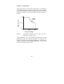
1
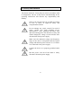
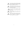
Standard Power Pack P25T
Order-No. 040-850
Manual
May 2009
!!Attention!!
Please read this manual carefully
prior to operating the device
Biometra GmbH
Rudolf-Wissell-Straße 30, D-37079 Göttingen
P.O. Box 1544, D-37005 Göttingen
Phone: ++49 – (0)5 51 / 50 68 6-0
Fax:
++49 – (0)5 51 / 50 68 6-66
E-mail: Info@biometra.com
Internet: http://www.biometra.com
Service Division
Rudolf-Wissell-Straße 14-16, D-37079 Göttingen
Phone: ++49 – (0)5 51 / 50 68 6-10 or -12
Fax:
++49 – (0)5 51 / 50 68 6-11
E-mail: Service@biometra.com
1.0 Intended Uses and Specification
The Biometra Power Pack P25 T is suitable for PAGE, SDSPAGE, agarose gel electrophoresis, blotting and electroelution
of proteins and DNA/RNA from gels.
The Power Pack P25 T is intended for use with any
electrophoresis applications designed to operate below 400
volts and 500 milliamps DC (electrophoresis) or 200 volts and
1000 milliamps DC (blotting). Four sets of outputs operate in
parallel to provide 0 to 400 volts, up to 1000 milliamps, and
up to 200 watts in constant voltage or constant current mode.
Voltage and current setting is adjustable in steps of 1V and
1mA.
In addition, the Power Pack P25 T offers a timer function,
which shuts down the output voltage after a defined time. The
timer can be set between 1 minute and 1999 minutes.
A single LCD display provides output voltage or current
readings.
1
2.0 Technical Data
Type Output:
Max. Voltage:
Max. Current:1
Max. Power:
Constant Voltage and Constant Current
400 VDC
1000mA in the range 0-200VDC
<1000mA in the range 200-400VDC
200 W, continuous
Timer:
1 minute to max. 1999 minutes
Output Display:
LCD-display, 3.5 digits, selectable
between display mA, V and min.
Resolution 1 mA, 1 V, and 1 min.,
respectively
Accuracy:
+- 5% v.M.
(for U, I >= 0,05 * Umax, Imax)
+- 5% of 0,05 * Umax, Imax
(for U,I < 0,05 * Umax, Imax)
Arithmetic mean over 3 s, Ts = 0.4 s
Number of Output
Terminals:
Four sets of 4 mm safety-sockets
Input Power:
Allowable deviation:
100–240VAC/50-60Hz/max. 300W
+6/-10%
Ambient Operating
Temperature Range:
0 to 40°C
Humidity:
0 to 70%
Dimensions:
(W x L x H) 26.5 x 25.0 x 9.5 cm
Weight:
3 kg
The Power Pack P25 T is designed for use with AC net supply
voltages between 100 Volt and 240 Volt, 50-60Hz. It is a
switched mode power supply providing voltage and current
controlled DC power, respectively. The DC output is free of
ground and short-circuit proof.
1
See also chapter 5.10
2
3.0 Safety Instructions
The Power Pack P25 T must only be used in accordance with
its designation. The use of this device unconformably to the
operating instructions will dissolve any responsibility and
liability.
Observe the relevant rules for accident prevention
as well as those of approved safety and
occupational medicine!
Do not attempt any repair yourself. In need of
repair, consult your local qualified service
representative. Only qualified personnel may
open the housing parts. The inner device may still
contain dangerous voltage several minutes after
disconnection from power supply.
Make sure the indicated voltage and frequency
range of the device corresponds with the system
voltage and that the power switch is on “0” before
it is connected to the power supply.
Connect the device to a properly grounded outlet
only!
Pull the power cord out of the outlet to safely
disconnect from the power supply.
3
Use exclusively the provided power cord or one
that meets the legal requirements.
Pay attention to the dimensioning of the fuses and
replace them if required. The fuse holder is
located in the lower part of the power connector
on the back side of the Power Pack. The
following fuses are required:
Micro-fuses, slow blow
2 x 5A; 250 V
"Caution: For continued protection against risk
of fire, replace only with same type and rating of
fuse".
"Caution: Double pole/neutral fusing, disconnect
power before changing fuse"
In order to ensure the safe electrical
disconnection the floating outputs must never be
grounded.
Make sure that your test setup always complies to
this condition.
Only safe electrical cords certified according to
IEC / EN 61010-2-031 may be connected to the
power outputs.
Make sure the Power Pack P25 T is located in a
safe and dry place, in proximity to the
electrophoresis devices powered. Keep away
from liquids. Should a liquid penetrate the P25 T,
disconnect the device immediately.
4
Do not operate in a damp or humid environment
where condensing moisture may lead to creeping
current. See chapter 2 (Technical Data) for
ambient operating temperature range.
When moving from a cold to a warm room, allow
8 hours before reusing the device in order for it to
reach the ambient temperature and for possible
condensation to evaporate.
Use only mild, non-abrasive detergents. Carefully
clean the device to avoid liquids penetrating the
inner housing.
When positioning the P25 T, make sure the
ventilation openings on the back side are not
covered.
Should the Power Pack become extremely warm,
smoke or display unusual information while in
operation, discontinue use immediately and
contact a qualified service representative.
5
4.0 Set Up
4.1 Content
•
•
•
Power Pack P25 T
Manual
Power Cord
4.2 Unpack and Check
Your Biometra Power Pack P25 T has been carefully packed
to ensure its safety. Please unpack it carefully, control the
integrity of its content and inspect the device. Report any
damage immediately to BIOMETRA!
Do not operate a device which is in no proper condition.
Should you have a complaint, return the complete system in its
original packing by following the return instructions (see
chapter 8.0).
!!Attention!!
Please send back the enclosed postcard along with the
filled out Warranty Certificate to Biometra in order
to claim the full warranty!
6
4.3 Power Supply
Before connecting, make sure the actual voltage complies with
the voltage range indicated on the type label.
Caution:
The Power Pack P25 T must be grounded!
4.4 Location
The Power Pack P25 T must be located in a dry and safe place.
Do not place an electrophoresis chamber on the power supply
device. The ventilation openings on the back side must not be
covered by other devices, furniture or fixtures. A sufficient air
flow for convection cooling must be provided.
4.5 Electrophoresis Chamber Connection
The electrophoresis chamber is connected to the Power Pack
P25 T by safety cords. Use exclusively electrophoresis devices
with safety connectors.
Switch off the Power Pack P25 T while
working on the test equipment setup.
7
5.0 Operation
5.1 Power On
Establish the connection to the electrophoresis chamber(s)
before switching on the Power Pack P25 T. Then switch on the
device using the power switch. A green light appears over the
power switch when power is turned on.
When power is turned on, the P25 T sets the output
voltage or current to the latest value stored.
Should you be unsure of the latest saved settings, detach all
connections to the electrophoresis chamber and switch on the
Power Pack P25 T in order to check the voltage or current
settings (see chapter 5.4 Voltage Setting).
The device must always be turned off before the
supply line to the electrophoresis chamber is to be
connected or removed for any given reason (power
switch on “0” and LED not illuminated).
5.2 Timer Mode On/Off
The “TIMER” button sets the Power Pack P25 T on timer or
continuous mode. When the timer is activated (illuminated
LED left of timer button) the output voltage will switch off by
itself after the given time interval has elapsed (see chapter 5.3
and 5.6 to start the timer and set time intervals).
8
5.3 Voltage On/Off
To turn the output voltage on or off, press the “OPERATION”
button. A timer will start counting when the timer function of
the device is activated. The output voltage will switch off by
itself after the given time interval has elapsed. A green LED
(left of “OPERATION” button) shows when the output
voltage is turned on.
Operating this button does not constitute a safe
disconnection from the power source. The device must
always be turned off before the supply line to the
electrophoresis chamber is to be connected or removed
for any given reason (power switch on “0” and LED
not illuminated).
9
5.4 Voltage Setting
First turn off the output voltage by using the “OPERATION”
button.
Then, by using the “SELECT” button, switch to “VOLT” on
the display. Set the desired output voltage by turning the knob.
In normal mode, the display shows the output voltage (actual
value). By turning the knob, the display changes from the
actual value to the desired set value, recognizable by the
flashing “VOLT” LED indicator. The desired value increases
with every clockwise rotation and decreases with every
counter clockwise rotation. Depending on speed and direction
of the rotation, the value will augment or reduce in steps of
1V, 10V or 100V. A set value modified by the user will, 3
seconds after the last operation of the knob, precede all other
values and will be set as the desired output voltage.
The voltage value (V) should be set without any
device connected!
10
5.5 Current Setting
Turn off the output voltage by using the “OPERATION”
button.
Then, by using the “SELECT” button, switch to “mA” on the
display. Set the desired output current by turning the knob.
In normal mode, the display shows the current conduction
(actual value). By turning the knob, the display changes from
the actual value to the desired set value, recognizable by the
blinking “mA” LED indicator. The desired value increases
with every clockwise rotation and decreases with every
counter clockwise rotation. Depending on speed and direction
of the rotation, the value will augment or reduce in steps of
1mA, 10mA or 100mA. A set value modified by the user will,
3 seconds after the last operation of the knob, precede all other
values and will be set as the desired output current.
The electric current value (mA) should be set
without any device connected!
11
5.6 Time Interval Setting
By using the “SELECT” button, switch to “TIMER” on the
display. Set the desired time interval value by turning the
knob.
In timer mode, the display shows the remaining time period
(actual value). If time is up or the device is set on continuous
operation mode the value “----” will appear. By turning the
knob, the display changes from the actual value to the desired
set value, recognizable by the flashing “TIMER” LED
indicator. The desired value increases with every clockwise
rotation and decreases with every counter clockwise rotation.
Depending on speed and direction of the rotation, the value
will augment or reduce in steps of 1 minute, 10 minutes or 100
minutes. A default value modified by the user will, 3 seconds
after the last operation of the knob, precede all other values.
5.7 Monitoring Voltage, Current and Timer
5.7.1 Monitoring Set Values
Choose the desired measurement category by using the
“SELECT” button in order to monitor the default voltage and
current values. Then turn the knob to the right or to the left by
one detent and the LCD displays will show the desired set
value of the corresponding measurement. The value appearing
on the display will, 3 seconds after the last operation of the
knob, precede all other values. The LCD display will then
automatically be switched to the actual value.
12
5.7.2 Monitoring Actual Values
Choose the desired measurement category at any time by using
the “SELECT” button in order to control the output voltage
and current. In doing so, only the LCD display will be
switched. The supplied current or applied voltage will not be
affected by this operation.
5.8 Working with Constant Voltage
Adjust the voltage controller’s set value to the desired output
voltage (see chapter 5.4 Voltage Setting) when working with
constant voltage. Then select the maximum possible or
allowable value for the current controller’s set value. The
current controller’s set value will then be the maximum
possible or allowable value chosen (see chapter 5.5 Current
Setting).
The Power Pack P25 T supplies a constant output voltage until
reaching the selected current limit (voltage control). The
output current then varies according to the ohmic resistance of
the electrophoresis chambers. The output of a constant voltage
will be shown by the LED indicator “VOLTAGE” (see chapter
6.4 Operating Status Display).
Should the maximum allowable output current be exceeded,
the Power Pack P25 T will limit the current and the output
voltage will drop.
Application example:
An agarose gel electrophoresis should be conducted with a
constant voltage of 150V. For safety reasons the output
current should not exceed 300mA. The following set values
will be applied:
Output voltage:
Output current:
150V
300mA
13
5.9 Working with Constant Current
Adjust the current controller’s set value to the desired output
current (see chapter 5.5 Current Setting) when working with
constant current. The voltage controller’s set value will then
have been selected so high that the device will switch to
current limit mode (see chapter 5.4 Voltage Setting).
When the current output has reached the desired set value, the
Power Pack P25 T will limit the current. The voltage output
will then adjust to the ohmic resistance of the electrophoresis
chamber and the current output will remain constant.
The LED indicator “CURRENT” (see chapter 6.4 Operating
Status Display) is illuminated throughout the current limitation
mode.
Should the set value for the voltage controller be
selected too low, the output voltage will therefore not
suffice to reach the desired current.
The output power of the Power Pack P25 T is limited
to 200W. The maximum allowable current output of
the device is limited to 200V as shown in figure 1 of
chapter 5.10.
Application example:
A semi-dry blot should be conducted with a constant current of
800 mA. For safety reasons the output voltage should not
exceed 50V. The following set values will be applied:
Output voltage:
Output current:
50V
800mA
14
5.10 Power Limitation
The output power of the Power Pack P25 T is limited to
200W. Should the user’s selected voltage and current defaults
exceed the maximum allowable output power, the device will
reduce the default set value of the output current as shown in
figure 1.
Output Current
1A
Power
Limitation
0,5 A
0A
0V
200 V
400 V
Output Voltage
Figure 1:
Automatic limitation of the output current at
high output voltage values
The “CURRENT” and “VOLTAGE” LED indicators are both
illuminated when the current limitation is accessed (see
chapter 6.4 Operating Status Display) to give a signal that the
output current, due to the “power limitation”, is lower than
the value originally set by the user.
15
5.11 Switching Off
The Power Pack P25 T can be turned on or off by pressing the
on/off switch.
The device must always be turned off before the
supply line to the electrophoresis chamber is to be
connected or removed for any given reason (power
switch on “0” and LED above not illuminated).
16
6.0 Status Notification
6.1 Power ON LED
A green LED located above the on/off switch shows, along
with the on/off switch position, if the Power Pack P25 T works
properly.
on/off switch
position
“O”
“I”
“I”
LED
Meaning
indication
dark
No error:
Power off
green
No error:
Power on
dark
Error:
• No connection to power
• Faulty fuse
• Device failure
The Power On LED remains dark although the device is
switched on when there is an operation or hardware failure. In
such case, please verify that
•
•
•
the power outlet supplies electricity,
the Power Pack P25 T is correctly connected to the
power source,
the fuses in the power inlet socket are not defective.
Caution: Disconnect the device from the power
supply by unplugging the power cord before any
fuse replacement!!!
17
6.2 Display Indication
The actual and set values for the voltage and current outputs
will alternatively be shown on the LCD display (see chapter
5.7 Monitoring Voltage, Current and Timer). The three LEDs
on the right side of the display indicate to which parameter the
value shown on the display belongs. The following rules
apply:
LED indication
“mA” – LED illuminated
“VOLT” – LED illuminated
“TIMER” – LED illuminated
“mA” – LED flashes
Display indication
Output current in mA
Output voltage in volt
Remaining time in minutes
Set value for the current
control in mA
Set value for the voltage
control in volts
Set value for the timer in
minutes
“VOLT” – LED flashes
“TIMER” – LED flashes
6.3 TIMER and OPERATION display mode
Two LEDs next to the “OPERATION” and “TIMER” buttons
indicate if the timer function is activated and if the output
voltage is turned on or not. The following rules apply:
LED indication
“TIMER” – LED on
“TIMER” – LED off
“OPERATION” – LED on
“OPERATION” – LED off
Display indication
Timer mode
Duration mode
Output voltage activated
Output voltage deactivated
18
6.4 Operating Status Display
The Power Pack P25 T is in one of the following three
operating modes “voltage limitation”, “current limitation” and
“power limitation” depending on the selected voltage and
current settings and the ohmic resistance of the electrophoresis
chamber. The operating mode is indicated by the two LEDs
located below the display. The following rules apply:
LED indication
Display indication
“CURRENT” – LED illuminated Current limitation
“VOLTAGE” – LED illuminated Voltage limitation
“CURRENT” – LED and
Power limitation
“VOLTAGE” – LED illuminated
In the “voltage control” mode the output voltage will remain
equal to the selected value (see also chapter 5.8 Working with
Constant Voltage).
Should the output current exceed the selected default value,
the “current limitation” function of the Power Pack P25 T is
activated. The output voltage is now adjusted to the ohmic
resistance of the electrophoresis chamber. The output current
remains limited to the selected default value (see also chapter
5.9 Working with Constant Current).
Should the user’s selected voltage and current defaults exceed
the maximum allowable output power of 200W, the device
will reduce the maximum allowable output current according
to figure 1 in chapter 5.10. Both LED indicators are
illuminated when the current limitation is accessed to indicate
that the output current, due to the “power limitation”, is lower
than the value originally set by the user.
19
7.0 Cleaning
Disconnect the Power Pack. Use only mild, non-abrasive
detergents and a slightly moistened soft cloth. Do not use
solvents, soak while cleaning or immerse in water!
20
8.0 Service
Should you have any problem with the device, please contact
our service division or your local Biometra dealer:
Biometra
GmbH
Service Division
Rudolf-Wissell-Straße 14-16, D-37079 Göttingen
Phone: ++49 – (0)5 51 / 50 68 6-10 or -12
Fax:
++49 – (0)5 51 / 50 68 6-11
E-mail: Service@biometra.com
Please follow the return instructions when returning the
device:
Return instructions
♦ Return only faulty devices. Please contact the technical
support of Biometra (Phone: ++49 - (0)5 51/50 68 6 - 10
or - 12) to get an RAN number.
♦ Use the original packing or a similar robust packing when
returning the material.
♦ Mark the outer packing with “CAUTION! SENSITIVE
ELECTRONIC INSTRUMENT!” and the RAN number
sticker. Deliveries without RAN number can not be accepted!
♦ Please include a precise description of the problem and
preferably one that also points out by which procedure the
failure occurs or where it originates.
♦ Important:
Clean every part of the device from residues such as
chemical, radioactive and dangerous biological
contamination.
Please
confirm
in
writing
(Equipment Decontamination Certificate) before
every return that the device is free of radioactive and
21
dangerous biological contamination. Contaminated
devices sent to Biometra will be refused!
♦ The sender will be liable for the repair order in case of
damage resulting from an inadequate decontamination of
the device.
♦ Please include a note with the following information:
a) Sender’s name and address
b) Contact person and phone number in case of
inquiry.
22
Equipment Decontamination Certificate
To enable us to comply with german law (i.e. §71 StrlSchV, §17 GefStoffV and §19 ChemG) and to avoid
exposure to hazardous materials during handling or repair, will you please complete this form, prior to the
equipment leaving your laboratory
COMPANY / INSTITUTE _____________________________________________________________________
ADDRESS __________________________________________________________________________________
TEL NO _____________________________
FAX NO _____________________________
E-MAIL
____________________________________________________________________________________________
EQUIPMENT
If on loan / evaluation
Model
Serial No
__________
__________
__________
__________
__________
__________
__________
__________
Start Date: ____________ Finish Date _____________
Hazardous materials used with this equipment
____________________________________________________________________________________________
____________________________________________________________________________________________
____________________________________________________________________________________________
Has the equipment been cleaned and decontaminated? YES / NO (delete)
Method of cleaning / decontamination
____________________________________________________________________________________________
____________________________________________________________________________________________
____________________________________________________________________________________________
NAME ________________________________
POSITION __________________________________
(HEAD OF DIV./ DEP./ INSTITUTE / COMPANY)
SIGNED ______________________________
DATE ______________________________________
PLEASE RETURN THIS FORM TO BIOMETRA GMBH OR YOUR LOCAL BIOMETRA
DISTRIBUTOR TOGETHER WITH THE EQUIPMENT.
PLEASE ATTACH THIS CERTIFICATE OUTSIDE THE PACKAGING. INSTRUMENTS WITHOUT
THIS CERTIFICATE ATTACHED WILL BE RETURNED TO SENDER.
23
Note for Disposal of Electric/Electronic Waste
This symbol (the crossed-out wheelie bin) means,
that this product should be brought to the return
systems and/or separate systems available to endusers according to yours country regulations, when
this product has reached the end of its lifetime!
For details, please contact your local distributor!
This symbol applies only to the countries within the EEA*.
*EEA = European Economics Area, comprising all EU-members
plus Norway, Iceland and Liechtenstein.
24
9.0 Notes
______________________________________________
______________________________________________
______________________________________________
______________________________________________
______________________________________________
______________________________________________
______________________________________________
______________________________________________
______________________________________________
______________________________________________
______________________________________________
______________________________________________
______________________________________________
______________________________________________
______________________________________________
______________________________________________
______________________________________________
______________________________________________
______________________________________________
______________________________________________
______________________________________________
______________________________________________
______________________________________________
______________________________________________
______________________________________________
______________________________________________
______________________________________________
______________________________________________
______________________________________________
______________________________________________
______________________________________________
25
EU - Konformitätserklärung
EC - Declaration of Conformity
Göttingen, den 01. 10. 2004
im Sinne der EG-Richtlinie über elektrische Betriebsmittel zur Verwendung
innerhalb bestimmter Spannungsgrenzen 73/23/EWG
following the EC directive about electrical equipment for use within certain
limits of voltage 73/23/EEC
und / and
im Sinne der EG-Richtlinie für die elektromagnetische Verträglichkeit
89/336/EWG.
following the EC directive about the electromagnetic compatibility
89/336/EEC .
Hiermit erklären wir, daß das folgende Power Pack mit Timerfunktion,
Herewith we declare that the following Power Pack with Timer,
Typ / type:
Best.-Nr. / Order No.
Standard Power Pack P25T (Rev. b)
040-850
den grundlegenden Anforderungen der
corresponds to the basic requirements of
EG-Niederspannungsrichtlinie 73/23/EWG und der
EC low voltage directive 73/23/EEC and the
EG-Richtlinie über die elektromagnetische Verträglichkeit 89/336/EWG
entsprechen.
EC directive about the electromagnetic compatibility 89/336/EEC .
Folgende harmonisierte Normen wurden angewandt:
The following harmonized standards have been used:
EN 60601-1-2:2001
EN 55011:1998 + A1:1999 + A2:2002
EN 61000-3-3:1995 + A1:2001
EN 61010-1:2001
Dr. Jürgen Otte
Quality Manager
26
EN 61000-3-2:2000
EN 61000-6-1:2001
Warranty
This Biometra device has been accurately produced and the
quality thoroughly controlled before delivery and is therefore
guaranteed to correspond to the product specifications in this
manual. Biometra offers a 24-month warranty on defective
parts under the following conditions:
This warranty is valid for 24 months from date of shipment to
the purchaser through Biometra or an authorized dealer and
can not be assigned to a third party without Biometra’s written
agreement.
This warranty is limited to the product and, if applicable, to
the standard original accessories. It is presumed that this
device will exclusively be operated in accordance with
Biometra’s instructions.
Defective parts returned within the warranty period will be
repaired or replaced without any charge by Biometra. This
warranty does not cover damage caused by misuse, neglect or
normal wear.
______________________________________________
Biometra GmbH
Rudolf-Wissell-Straße 30, D-37079 Göttingen
P.O. Box 1544, D-37005 Göttingen
Phone: ++ 49 (0)5 51 / 50 68 6-0
Fax:
++ 49 (0)5 51 / 50 68 6-66
E-mail: Info@biometra.com
Internet: http://www.biometra.com
27