1
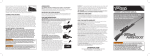
K-80 & K-20 CL AY TARGE T SHOTGUN Instruction Manual K R IE GH O F F K- 8 0 A ND K-2 0 C L AY TA RGE T S H O T GUNS Handling and Service Instructions for the Krieghoff K-80 and K-20 Clay Target Shotguns. With proper care and periodic maintenance your Krieghoff can provide a lifetime of shooting pleasure. H. Krieghoff GmbH, Ulm, Germany. Do not discharge a gun towards any hard surface, including water, because both shot and bullets can ricochet in unpredictable directions. Your Krieghoff is equipped with a mechanical safety. Learn how it functions and use it. 11/2013 NEVER POINT A FIREARM TOWARDS ANOTHER PERSON OR YOURSELF! “K-80” and “K-20” are registered trademarks of 2 C AU T I O N Read and understand all instructions before using this or any other firearm. Read, learn, and observe the safety procedures described on page 4. Always point a firearm in a safe direction so that it does not endanger anyone, including yourself. Shot can be dangerous to over 400 yards, and bullets may range as far as three miles. CO N T EN T S Gun Safety ............................................................ 4 Adjusting Trigger Position ....................................... 21 Assembly and Disassembly .................................... 7 Release Triggers ..................................................... 22 Stock Removal and Reinstallation ........................... 9 Stock Finish .......................................................... 24 Locking System ..................................................... 10 Adjustable Comb.................................................... 25 Safety .................................................................... 11 Adjustable Butt Plate .............................................. 28 Point of Impact Adjustment .................................... 13 Removing, Cleaning and Reinstalling Ejectors .......... 29 Steel Shot Ammunition .......................................... 17 Specific Instructions – K-80 Parcours ....................... 31 Screw-in Chokes .................................................... 18 Maintenance .......................................................... 32 Barrel Selection ..................................................... 20 Choke Tube Designations ....................................... 35 3 GUN S A F E T Y Gun safety is your responsibility! Read and observe these essential rules. ➡ A loaded firearm can cause SERIOUS INJURY OR DEATH! When handled properly and according to basic safety rules, it is safe. ➡ Accident prevention is the responsibility of anyone handling a firearm. THINK GUN SAFETY! ➡ Handle a gun as if it is loaded. EVERY GUN IS A LOADED GUN! ➡ Never point a firearm at yourself or anyone else. ➡ Never hold a firearm at the muzzle. Never rest the muzzle on your foot. 4 ➡ Before handling and loading a firearm, be sure you know how it functions. Read the instruction manual. ➡ Control your shooting. Be aware of the range of the ammunition you shoot. This may vary from several hundred yards for shotgun pellets to several miles for rifle bullets. Never shoot at a hard surface or at water because shot and bullets can ricochet in any direction with sufficient force to cause injury or death. ➡ Be ABSOLUTELY CERTAIN that it is safe to shoot in the direction you intend to fire. If there is the slightest question or doubt, DO NOT SHOOT! ➡ When shooting targets, always keep your firearm open until it is your turn to shoot. When hunting, keep your safety on except when actually shooting. ➡ Mechanical safeties are an important additional safety feature, but they are no substitute for safe gun handling! Always handle a firearm as if it is loaded and ready to fire. Because of the strictly controlled circumstances of competitive shooting, it may be advantageous to have no mechanical safety or one that can be made inoperative. If your gun has no safety, use it only for clay target competition. If your gun has a safety that can be made inoperative, shoot it with the safety inoperative only for clay tar- get competition. When shooting in the field, you MUST make the safety operational and use it. ➡ Competitive shotguns may have a pull trigger or a release trigger. Always familiarize yourself with the trigger system of any firearm before you shoot it. Refer to your instruction manual and then dry-fire the firearm until you are completely familiar with its operation. ➡ NEVER use ammunition that appears to be damaged or irregular in any way. ALWAYS use ammunition that is made for the specific chamber size and gauge/caliber of your gun. ➡ Use factory loaded ammunition only. Factory ammunition is manufactured with the most sophisticated and reliable equipment available. The quality and consistency of factory loaded ammunition is essential to firearm safety. ➡ NEVER use reloaded ammunition! Shooting improperly reloaded or remanufactured ammunition can result in property damage, serious injury or death. Use only factory loaded ammunition to protect yourself and your warranty. ➡ Keep your firearm clean. Prevent dirt and foreign objects from entering the action and the barrel. Before loading a firearm, inspect the barrel to be certain that it is clean and free of foreign objects. Shooting with ANY obstruction in the barrel – dirt, mud, snow, grease, or remnants of wads, bullets, or bullet jackets – can cause a barrel to bulge or rupture and can cause SERIOUS INJURY or DEATH. ➡ Firearms must be protected from corrosion, which can affect their safe and proper function. Firearms should be kept thoroughly clean, and all metal surfaces should be protected with a light film of gun oil especially during storage. Store firearms uncovered or in a gun sleeve that can breathe, and provide them with proper ventilation. 5 ➡ Always wear eye and ear protection when shooting. ➡ NEVER use alcohol or any other drug that can alter consciousness and judgment before or during the handling of a firearm. ➡ Store all firearms unloaded! Be absolutely certain that the chamber of every gun is empty. ➡ Store all firearms in a LOCKED cupboard or safe and OUT OF THE REACH OF CHILDREN. Follow the regional or national laws and regulations in regards to gun and rifle storage. 6 A S S E MB LY A ND DIS A S S E MB LY 1 2 AS S E M BLY Lubricate gun as described on page 33. Make sure both ejectors are pushed in. Open the top lever. Holding the barrels in the left hand as shown (see illus. 1), brace the muzzle between your legs. Hold the receiver and stock by the pistol grip with the right hand and engage the barrels into the action at about a 45° angle, using pressure with the ball of the left hand to direct the barrels onto the pivots (see illus. 2). Using a rocking motion up and down, seat the barrel cutouts fully onto the pivots. Rotate the barrels on the pivots slightly to be certain that they are firmly seated, and then close the gun fully. Holding the assembled barrel and action in one hand, push the cocking levers up so that their axis is parallel to that of the barrels. With the free hand place the forend around the bottom barrel and then move it down so that the slots at the rear of the forend iron engage the cocking levers. The forearm can then be firmly pressed up into the latched position against the barrels. Make sure that the latch engages fully. Avoid striking the underside of the barrels or the receiver with the sharp edges of the forend iron. 7 DISASSEMBLY Disassemble the gun in the reverse order. Remove the forend. Then open the top lever and carefully remove the barrels by gently rocking and rotating them until they are disengaged from the pivots. Do not attempt to pry them off with a single motion because this may damage the finish of the bottom barrel or the receiver. 3 8 4 5 S T O C K R E MO VA L A ND R EINS TA L L AT IO N RE MOVAL Insert the stock wrench into the stock through the small hole in the recoil pad (see illus. 6). Unscrew the stock bolt 2–3 turns with the special T-handled stock wrench supplied. If necessary, you may lay the receiver on a flat padded surface and gently bump the handle of the stock wrench or the bottom of the pistol grip with the palm of the hand to loosen the stock from the receiver. R E I N S TALL AT I ON Insert the stock wrench and seat it firmly in the stock bolt. Use a light coat of gun oil to prevent any damages at the small hole in the recoil pad. Slide the stock straight on to the rear tangs and forward to meet the receiver. Push them together firmly. Again, be careful not to force the stock onto the receiver or to it rock up and down because this may damage the inletting. Seat the stock bolt in the bolt hole and tighten it firmly, but not excessively, with the stock wrench. Make certain that the bolt is completely disengaged and then carefully remove the stock to the rear. Do not move the stock up and down to loosen and remove it because this may damage the inletting. 6 7 9 L O C K IN G S Y S T E M The heart of the K-80 and K-20 locking system is a top latch (or locking cover) that slides forward when the gun is closed and engages the barrel flats. Even after many thousands of shots, any wear on the barrel flats is compensated for by the free forward movement of the locking cover, which holds the barrels as firmly as when they were new. When your gun is new, the top lever will stay slightly to the right. Over a useful life of many hundreds of thousands of rounds and as the gun wears in, the top lever will move to the left and the small gap between the top latch and the barrel flats will gradually decrease and eventually close. At that 10 point the locking system can be renewed and your Krieghoff given new life. For that reason contact your authorized Krieghoff Factory Service Center for details and options. 8 SAFET Y ACT IVATED SAFETY The Krieghoff K-80 and K-20 are equipped with a non-automatic sliding safety that has a round push button lock in its center. The safety is activated by pressing the button with the thumb and simultaneously sliding the safety switch to the rear to put the gun “on safe”. The gun is taken “off safe” and made ready to fire by depressing the button and sliding the safety switch forward. When the gun is “on safe”, the letter “S” appears just above the safety switch. When the gun 9 10 is “off safe” and ready to fire, the letter “S” is covered and not visible. 11 11 IN O PERATIV E SAF E TY Note: Lock the safety in the “off” position only when shooting clay targets under controlled conditions. Make the safety operative for ALL other shooting. The safety of the K-80 and K-20 can be locked in the “off safe” position and made inoperative. The purpose of this feature is to prevent the loss of a target in competition that results from inadvertently leaving the safety on. This feature is for use ONLY under the controlled conditions of clay target competition when guns are never loaded 12 until the shooter is on the shooting station or in the shooting cage. To lock the safety off, remove the stock and locate the screw on the left side of the top tang, adjacent to the safety. The screw is shown in illus. 10 and 11 on page 11 and will match the gun’s blue or nickel finish. Newer models have an allen screw in this location. Slide the safety forward and tighten the screw to lock the safety in the “off safe” position. To make the safety operative again, simply loosen the screw until the safety moves freely. P OIN T O F IMPA C T A DJ US T MEN T If you wish to have the bottom barrel pattern higher, select a ring which is lower in height at the dovetail. A higher ring will move the pattern lower. the point of impact. There are eight different hangers available for K-80 choke tube barrels and nine different hangers available for K-80 fixed choke barrels. Four hangers are available for the K-20. To install a new hanger, drive out the retaining pin (use 1.4 mm size of the puncher), and slide off the hanger to the front. Replace with the new hanger and reinstall the pin. ➡ B OT TOM BARREL O N LY The point of impact (POI) of the bottom barrel of the K-80 and K-20 can be raised or lowered in relation to that of the top barrel simply by changing the front barrel hanger. The hangers have dovetails of varying heights which change the point of impact of the bottom barrel (see illus. 12). 12 For easy reference each hanger is marked with a small number visible from the muzzle side. The lower the number, the higher 13 UN SIN GLE Model K-80 only First loosen the adjustment screw about one turn counterclockwise. Note that the slot of the screw can accommodate any one of a number of coins, so no special tool is necessary. Adjusting the rib downward toward barrel raises POI. Raising the rib away from the barrel lowers POI. Each line on the scale above the muzzle equals about 3 to 5 inches at 35 m (38 yds). Retighten the locking screws. Check the lock washers periodically to be sure that they provide enough friction to maintain the adjustment. 14 13 INST RUCTIO N S SPECIFI C TO TH E K-8 0 TRAP SPECIAL AN D DO UBLE T R AP SPECIAL All barrels feature a fully adjustable rib which allows you to lower or raise the point of impact. Adjustment of point of impact for the Over & Under and Unsingle Barrel All barrels including both barrels of over & under barrels are set by the factory to shoot a 70 %/30 % pattern high at 35 yds when shipped. Each barrel set, including each individual barrel on the over & under can be individually adjusted by changing either the front hanger (see page 13) and/or raising or lowering the rib. The range of adjustment is from a fairly flat shooting 60 %/40 % pattern to almost a full pattern high (100 %). How to lower and raise the rib Loosen the locking screw at the very front of the rib which locks the adjustment wheel. Use the 1.5 mm allen key supplied and remove the locking screw completely. The adjustment wheel is now free to turn. To raise the POI, turn the wheel clockwise so it moves downwards toward the 14 15 15 “U” (= POI up). Each reference serration on the rib will raise or lower the POI by approximately 10 %. I NS T RU C T I ONS S P E C I FIC TO TH E K- 8 0 & K- 2 0 P RO S P ORTER A ND K- 8 0 P RO T RA P Loosen and remove the locking screw at the top of the adjustment wheel with the 1.3 mm supplied allen key (see illus. 16). A spare screw is provided. With the adjustment wheel now free, you may turn the wheel clockwise to increase POI (as the rib gets closer to the barrel POI increases). ment wheel is lined up with the locking screw. For example, one serration below the standard 70 %/30 % marking would raise the POI of the barrels by 10 % to 80 %/20 % (in the case of an over & under both barrels simultaneously). The rib goes down, the barrel and POI go up. After the desired POI is dialed in put the locking screw back in the threaded hole at the front tip of the rib and tighten the locking screw using the 1.5 mm allen key supplied and making sure at the same time that one of the two holes on the knurled adjust16 After desired POI is reached, use the 1.3 mm allen key to reinstall and tighten the locking screw. 16 S T EEL S H O T A MMUNI T IO N All K-80 and K-20 barrels with choke tubes are proofed for steel shot. Steel shot greater than 3.2 mm must not be used in barrels that are not steel shot proofed (no “Lily” marking). Failure to adhere to this can cause damage to the choke ramp and ruin the barrel. Even for steel shot proofed barrels, if a maximum shot size of greater or equal to 4 mm is used, modified choke (0.5 mm) or less is mandatory. 17 S C R E W- IN C H O K E S Always unload a firearm before changing choke tubes. Never shoot a choke tubed barrel without a choke tube installed. It is very important that choke tubes be properly maintained and protected from damage. If chokes are not periodically removed from the barrel and cleaned, corrosion and rust may form between the choke tube and the barrel making it impossible to remove. Choke tubes should be removed and cleaned whenever the gun is cleaned. Apply barrel solvent to the choke tube and wipe it clean, paying particular attention to remove foreign particles from the threaded area and any plastic build up from the rear internal portion of the tube. Also apply solvent to and wipe clean the threads in the barrel itself. Apply a light coat of Krieghoff Gun Pro or other fine gun oil to the choke tube before reinstalling it in the barrel. Install the choke tube by hand. If you encounter any roughness or resistance, check to make sure that both the tube and the barrel are clean, free of debris, well-lubricated and undamaged. Examine them carefully for damage if they are ever dropped, stepped on, or otherwise dented. If a choke tube is dented or otherwise damaged, its rear edge could protrude into the bore of the barrel. When the gun is fired, the shot charge could be impeded by the damaged tube, and the barrel could be totally destroyed. Handle the choke tubes with care. Store them in their protective cases. 17 18 NEVER shoot with a damaged choke tube. If you discover that a choke tube is damaged, discard it immediately. For choke tube selection see page 35. Whenever you change or reinstall choke tubes, look through the bore to make absolutely certain that the tube does not protrude into or obstruct the barrel in any way. Failure to do so could result in severe damage to the barrel and severe injury to the shooter or those around them. To install a choke tube, screw it all the way in by hand and tighten it gently with the choke tube wrench (see illus. 18). Never apply force when installing a choke tube and never over tighten. 18 19 B A R R EL S EL E C T IO N The K-80 and K-20 single trigger is mechanical and does not rely on recoil to select the second barrel. This gives the advantage of quick resetting for the second shot and makes it possible to fire the second barrel even if the first barrel misfires. When the selector lever, located in front of the trigger, is pushed to the left by the side marked B (bottom barrel), the bottom barrel fires first. To fire the top barrel first, push side T (top barrel) to the right (see illus. 20). If you wish to lock the selector, tighten the front screw in the trigger with the small allen key provided. 20 Note: Do not over tighten the screw. When the gun is shipped from the factory, the selector locking screw is not tightened. 19 20 A DJUS T IN G T R IGGER P O SI T IO N The locking screw (B) for the trigger position, must always be tightened down to prevent the trigger from moving during shooting. To adjust the trigger position, loosen both screws about one turn with the hex key provided. Slide the trigger to the desired position and gently retighten the trigger locking screw. The selector locking screw (A) may also be tightened if you want to lock the selector. Note: To prevent damage, it is important to never over tighten either of the locking screws. A B A: Locking screw for barrel selection 21 B: Locking screw for trigger position 21 R EL E A S E T R IGGER S Model K-80 only Release triggers, which are particularly popular in American trapshooting, fire the gun, as the name suggests, when the trigger is released rather than when it is pulled. The idea is to have the trigger finger make a smooth, almost effortless move by simply “letting go”. To fire a gun equipped with a release trigger, you must first set the trigger. Facing in the direction that you intend to shoot and with the gun mounted to the shoulder, you pull the trigger until you feel a complete and positive stop. You must hold the trigger in that position until you are ready to shoot. Call for the target, swing through it, and release the trigger to fire the 22 gun. If for any reason you do not want to fire the gun after you have set the trigger, you must disengage the trigger to prevent the gun from firing. To do this, maintain a firm hold on the trigger with your trigger finger, being absolutely certain that the gun is pointed in a safe direction. With your opposite hand, open the gun with the top lever in the usual manner. Allow the gun to open. The release trigger is now disengaged. To shoot, close the gun and proceed in the manner described before. It is absolutely necessary that you thoroughly understand the release trigger mechanism and familiarize yourself with it. Dry-fire the gun repeatedly with snap caps until you are complete- ly familiar with the way the trigger feels and handles. NEVER SHOOT A GUN WITH RELEASE TRIGGERS UNTIL YOU HAVE DRY-FIRED IT AND THOROUGHLY UNDERSTAND THE TRIGGER AND HOW TO DISENGAGE IT. NEVER SHOOT A GUN UNTIL YOU ARE COMPLETELY FAMILIAR WITH ITS TRIGGER SYSTEM AND ALL OF ITS OPERATING AND SAFETY FEATURES. Krieghoff K-80’s can be ordered with factory release triggers, or the triggers may be installed later. Release triggers are available in two configurations: single release and double release. S ING L E RELEASE With a single release trigger, the first barrel is set and fired as a release, and the second shot is fired as a conventional pull trigger. D OU BL E RELEASE With double release, the second barrel must also be set and released to fire. 23 S T O C K F INIS H EPOXY LACQ UER F I N I S H Krieghoff K-80 and K-20 standard stocks are finished with a specially formulated epoxy lacquer which seals the wood completely so that it cannot be damaged even in the wettest weather. If your gun does get wet, however, the stock, forend, receiver, and barrels should be wiped down and allowed to air dry separately. After the metal components are completely dry, apply a light coat of gun oil. After the stock and forend are dry, they require no further care. 24 O IL F I NI S H Krieghoff K-80s and K-20s with custom stocks will be delivered with a traditional European oil finish. These stocks are not completely waterproof, and their finish requires periodic maintenance. During the first year of use they should be treated several times. Apply a very small amount (two or three drops) of stock oil to each side of the stock and forend and rub it in by hand until it is evenly spread and thoroughly absorbed into the wood. This process should be routinely repeated at least once a year thereafter. It is most important, how ever, that oil finished stocks and forends be thoroughly air dried and retreated with oil after exposure to rain or heavy moisture. Note: Custom stocks and the stocks of specific competition shotgun models could deviate from the standard described. A DJ US TA B L E COMB Krieghoff stocks are adjustable at the comb for height and off-set. The drop at heel and comb can be adjusted from approx. 1-1/4" to 1-5/8". The comb can also be adjusted sideways for off-set. The height of the comb is determined by two adjustment screws in the base of the comb which rest on the steel plate inlet in the stock. The height adjustment is therefore maintained by the support screws rath- 22 23 er than the clamp screws which hold the comb and stock together, a design feature that assures that the adjustment cannot change during shooting. 24 25 26 ADJUSTIN G FO R H E IG H T To change height adjustment, carefully insert the small allen key supplied with adjustable stocks into the holes on the right side of the comb and loosen the clamp screws by turning them counterclockwise for approximately two turns. Do not attempt to turn the clamp screws all the way out because this may damage the stock finish around the holes. the comb piece are two round steel plates inlet in the wood. Each of the plates contains a height adjustment screw. Use the allen key to adjust the screws, turning them counterclockwise (out) to raise the comb and clockwise (in) to lower it. Both adjustment screws should be at the same height when the comb piece is reinstalled, although the design allows for a limited pitch lengthwise. After loosening the clamp screws, pull the comb piece straight up and completely off of the stock. Rocking the comb piece from front to back as you lift it may make it stuck on the posts and more difficult to remove, so be sure to pull it straight off. Underneath Apply grease to adjustable comb posts to ease removal and installation. To reinstall the comb piece, align the holes in the steel plate with the guidepost on the stock and slide them directly onto the posts, again being careful not to rock the comb piece back and forth, until the height adjustment screws rest firmly on the steel plates. Then tighten the clamp screws firmly to hold the stock and comb together. Note that the height adjustment screws must rest firmly on the steel plates of the stock as described above or else the comb height will not be consistent and may actually change during shooting. ADJUSTIN G FO R O F FS E T Proceed as described before to take the comb piece completely off the stock. The guideposts located in the cutoff section of the stock are now accessible. Use the allen key to loosen the lock screw on the top of the guidepost and then slide it sideways in either direction for the desired amount of offset. Both posts should be moved about the same distance, although a slight variation is possible. Note the lines of calibration, which make it possible to check, maintain, and repeat the precise degree of adjustment. Note: The adjustable comb is a standard feature for many versions of the K-80 and K-20. It is available as an option on non adjustable stocks. 27 A DJ US TA B L E B U T T P L AT E ADJUSTABLE BU TT PLATE The optional Krieghoff adjustable butt plate offers the possibility to alter the plate’s position within four directions: ➡ stock drop (up and down) ➡ cast (left and right) ➡ vertical angle of the butt plate (twist) ➡ pitch This makes it possible to individualize the stock to a high degree. LE N GT H OF P U L L In combination with the adjustable butt plate, it is also possible to adjust the stock length within 6.5 mm (1/4") increments. There are spacers located between the stock and the pad adjustment device. Depending on how many of these spacers are stacked together, it is possible to alter the length of pull measurement. Please find a detailed description regarding the different settings of the butt plate in a separate instruction manual under: www.krieghoff.de/en/infoextra/ download-center 28 25 R E MO V IN G, C L E A NIN G A ND R EINS TA L L IN G EJE C T O R S IMP ORTAN T Always make sure a firearm is unloaded before cleaning. To ensure the proper function of the ejectors, clean the gun regularly. The new style ejector is easily distinguished from the older style ejector by the absence of the blued retaining screw on the ejector itself. The new style ejector has no such screw. It is held in place by the ball-andspring assembly, shown in illustration 26. The spring presses the ball bearing into a detent slot on the back of the ejector. R E M OVAL The ejectors may be removed for periodic cleaning, but special care must be taken in removing and reinstalling them. Work only over a flat surface covered with a towel or other soft material. To remove the ejectors, push both back gently until you feel resistance. Then very lightly, tap with plastic mallet until resistance disappears. Keep your thumb over the detent area while removing the ejector to keep the ball and spring from ejecting once the pressure is released. Hold the barrel horizontally, close to the covered table top, with the ejector to be removed facing downward. Slide the ejector out to the rear. As the ejector clears the ball-andspring, the ball will pop out, and the cush- ioned surface will catch it. Remove the ejector and set the ball aside. Remove the spring with a pair of tweezers. C L E A NI NG Clean the ejector and the ejector groove with fine quality cleaner. Coat the ejector and wipe it clean. If stubborn debris remains, remove it with a small cleaning brush. Spray the cleaner into the ejector groove and wipe it out. If the groove is particularly dirty, use a small brush, pipe cleaner, or cotton swab to remove remaining debris. Wipe the groove clean. Lubricate the ejector and ejector groove with a light coat of gun oil, like Krieghoff’s Gun Pro, and reinstall the ejector. 29 26 30 R E INS TA L L AT I ON Place the spring in the hole. Insert the ejector into the ejector groove, being certain that the ejector is on the proper side. When the ejector is on the proper side, the machined recess on the front outside of the ejector opens downward. Push the ejector in until the front end of the ejector is even with the hole. Place a small dab of gun oil on the spring and place the ball over the spring in the hole. Use a small flat screw driver or other useful tool to push the ball against the spring and into the hole. Simultaneously slide the ejector forward to cover the hole partially and to hold the ball. Remove the tool and slide the ejector the rest of the way forward. The ejector is properly reinstalled when the spring pushes the ball into the detent slot, resulting in an audible “click”. Slide the ejector back and forth to insure proper seating, and repeat the procedure for the second ejector. S P E C IF IC INS T RU C T IO NS – K- 8 0 PA RCO UR S The K-80 Parcours comes standard with fixed choke soldered rib barrels. This barrel design gives you a weight savings of 300 g. compared to the traditional K-80 Skeet or Sporting model. (“Lily” marking) is required. Optional Briley Thin Wall choke tubes are available allowing for full steel shot proofing. Utilizing a traditional sporting stock and forearm which is thinner than other K-80 competition models the Parcours is just as suitable for Hunting as it is for Clay Target shooting. As this barrel comes standard with fixed chokes, the maximum steel shot size allowed is 3.2 mm (1.25") regardless of choke constriction. If greater shot diameters are necessary, official steel shot proof 27 31 M A IN T EN A N C E The Krieghoff K-80 and K-20 must be properly maintained to insure a lifetime of reliable and consistent service. When assembling the gun, place a thin coating of Krieghoff Gun Glide or other high quality gun grease in the barrel pivots. Use only acid- and resign-free detergents for cleaning! Place a very light coat on the flat surfaces adjacent to the pivots; on the barrel lug; on the barrel flats where they are engaged by the top latch; and on the concave portion of the forend iron where it joins the receiver. Immediately after shooting and before casing the gun, its external metal surfaces 32 should be wiped down and lightly oiled. The bore and action of the gun should be thoroughly cleaned periodically. After disassembling the gun, wipe these surfaces to remove the grease and any grit that may have accumulated during shooting. The barrels must be cleaned after shooting to remove lead fouling and the build up of plastic from wads. Use a conventional bore solvent and follow the manufacturer’s instructions, saturating cleaning patches with the solvent and running them through the bore with a shotgun cleaning rod. For particularly stubborn fouling, apply more solvent and use a phosphor bronze cleaning brush. 28 Then alternate solvent-soaked and dry patches until the bore is clean and finish with a light coat of gun oil like Gun Pro. If your barrel is equipped with choke tubes, clean the barrel first with the tubes installed and then remove and clean the tubes themselves as described before. 29 cient grease, including the barrel pivots, barrel ears and forearm iron. Be very careful to keep these areas free of dirt particles. If you shoot in the rain or snow and your gun is wet, disassemble it, wipe it dry, and then allow it to air dry before applying a light coat of gun oil. When finished cleaning, we recommend relieving the tension on the mainsprings by dry firing with snap caps or empty shells. Be sure that all bearing surfaces have suffi33 AN N UAL SERV ICE For the dedicated clay target competitor, the Krieghoff Annual Service is recommended after every 15,000 to 20,000 rounds or every 2–3 years to keep your Krieghoff in top form and insure consistent performance. The gun is disassembled, cleaned, and relubricated. Minor springs and circlips are replaced and the receiver is fine tuned to original factory specifications. 30 34 C H O K E T UB E D E SIGN AT IO NS SCREW- IN CH O K E M AR K IN G S AR E AS FOL L OWS : 00 0 1 1+ 2 2+ 3 4 5 = = = = = = = = = C S IC LM M LIM IM F SF = = = = = = = = = Cylinder Skeet Improved Cylinder Light Modified Modified Light improved Modified Improved Modified Full Super Full = = = = = = = = = 0.00 mm (.000") 0.13 mm (.005") 0.25 mm (.010") 0.38 mm (.015") 0.51 mm (.020") 0.64 mm (.025") 0.76 mm (.030") 0.89 mm (.035") 1.02 mm (.040") 35 H. Krieghoff GmbH · Hunting and Sporting Arms Boschstrasse 22 · 89079 Ulm / Germany · P.O. Box 2610 · 89016 Ulm / Germany · Phone +49 7 31 / 4 01 82-0 · Fax +49 7 31 / 4 01 82-800 · www.krieghoff.de Krieghoff International Inc. · Serving the U.S. and North American Market P.O. Box 549 · 7528 Easton Road · Ottsville, PA 18942 USA · Phone (610) 847 - 5173 · Fax (610) 847 - 8691 · www.krieghoff.com