1
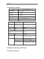
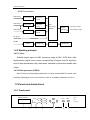
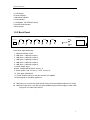
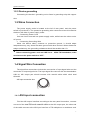
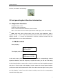
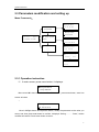
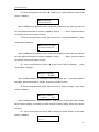
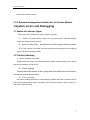
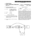
QPSK Demodulator
User Manual
V3.5
QPSK Demodulator
Charter 1 Product Outline
1.1 Outline
QPSK TS Demodulator used for receiving and transferring 5 routes DVB-S
channels to 5 routes TS stream signal directly, then convert via FPGA outputting ASI to
devices such as Multiplexer or Modulator. No need to do process of decompression,
encoding etc. The other ASI input route can receive EPG or other TS stream, and it has
inner multiplexer, It is widely used in satellite digital TV, data broadcasting, Internet, etc.
1.2 Features
z
z
z
z
z
z
z
z
z
z
z
Support 5 routes LNB independent input or loop input, 1 route ASI-TS stream input,
by inner multiplexer, it output one ASI-TS, and one backup of ASI-TS stream output;
Support EPG or other ASI-TS inputs multiplex by inner multiplexer.
LNB input frequency range: 950~2150 MHz;
Interface comply with ASI standard;
DVB/MPEG-2 both compatible;
SCPC/MCPC compatible, can receive all domestic and foreign non-encrypted digital
programs;
Polarization mode: Horizontal/vertical for optional;
F head for optional;
C/Ku band compatible;
Adopt ultra-low threshold integrated tuner, high reliability, good performance, power
off memory;
Stable and reliable performance, strong anti-interference capability.
Application:
z
z
z
Digital satellite television broadcasting;
MMDS digital TV front-end;
Digital cable television network
1
QPSK Demodulator
1.3 Performance Indicator
Model
QPSK TS Demodulator
Input Frequency
950~2150MHz
Signal level
-72~-22dBm
IF band width
27~36MHz
Modulate mode
QPSK(DVB-S)
Input port
75Ω
(British system, F-head)
Loop output
75Ω
(British system, F-head)
TS Input port
Package
ASI socket:BNC75Ω
1 route
188/204 bite(Optional)
format
Input speed
Output
ASI
ASI
Multiplexed and selected output port PID
amount
Output speed
Management
port
Normal
ASI
80Mbps
one group , two same outputs
<128
150Mbps
Ethernet port(RJ45)
10/100M (self-adaptive)
Size
44mm×482mm×330mm
Circumstances
0~45℃(work);-20~80℃(store)
attribute
Electrical source
110~220VAC±10%,50/60Hz,
35W
1.4 System Components and Principle
1.4.1 System components
2
QPSK Demodulator
QPSK Demodulator:
LNB input 1
Tuner Module
Demodulate
Module
LNB input 2
Tuner Module
Data
Processing
Module
Demodulate
Module
LNB input 5
Tuner Module
Demodulate
TS Main output
Output
Interface
TS Backup output
Module
TS input 6
Power
Power
Single Chip
LCD, Button
Administrator
1.4.2 Working principle
1.4.2.1 Tuner
Satellite signal input via LNB, frequency range at 950~2150 MHz, after
high-precision digital tuner comes corresponding IQ signal, then IQ signal be
sent to date demodulator chip, afterwards, standard synchronous parallel data
output.
1.4.2.2 Data processor (FGPA)
After FPGA got corresponding parallel data, it output standard MPEG-2 stream (ASI
interface) digital signal, for the use of devices such as, scrambler, modulator, and so on.
1.5 Panels and Instructions
1.5.1 Front panel
QPSK Demodulator
Power
Alarm
1
2
3
Lock1
Lock4
Lock2
Lock5
Lock3
Lock6
4
Enter
Menu
Digital
Video
Broadcasting
5
6
7
3
QPSK Demodulator
1-LCD display
2-Power indicator
3-Alarm/lock indicator
4-Lock indicator
5- UP/DOWN, LEFT/RIGHT Button
6-Confirm/Unlock button
7-Menu button
1.5.2 Back Panel
AC110V-220V/50/60Hz
Ethernet
LNB1
LNB2
LNB3
LNB4
LNB5
MUX
M1
ASI IN
IN
IN
IN
IN
IN
M2
From left to right followed by:
1. Network interface: RJ45
2. LNB input 1, LNB loop output 1;
3. LNB input 2, LNB loop output 2;
4. LNB input 3, LNB loop output 3;
5. LNB input 4, LNB loop output 4;
6. LNB input 4, LNB loop output 5;
7.ASI bit stream input
8.MUX, multiplexed bit stream ouput 1, 2
9. Power switch: “ON” for turn on, “OFF” for turn off.
10. Fuse pipe: 2A/AC250V
11. Power socket: connect to AC180~AC240V, 20~60MHz.
12.Ground pole for complete appliance.
z LNB input port: receive the signal which receive from the satellite antenna via F head.
z LNB loop output port: it can put the same satellite signal sources supply to other LNB
input port or to other input device.
4
QPSK Demodulator
Charter 2 Installation Guide
1.1 In spection up on recep tio n
Open the device packing carton, make sure to check all the packages for the
small parts, check the commodities according to the packing list or below items:
•
•
•
•
In
QPSK TS Demodulator
1set
User manual
1 pc
Dual Q9-ends coaxial cable
4 pc
AC power line
1 pc
case of any discrepancies, please contact the dealer at once!
1.2 Installation
Following below steps once you are ready to install the device. The every
details of installing will be described in rest of this chapter, please refer to the panel
instructions for the specific location. This chapter includes the following:
•
•
•
•
•
Check any possible losing or damage occur during the transport;
Get ready the good environment for installation;
Install QPSK TS Demodulator;
Connect to the signal lines;
Connect to the communication port (optional)
1.2.1 Device installation flow chart as following:
Acquisition
Check
Fixing
Device
Connecting
Grouding
Wire and
Power
Cord
Connecting
Signal Wire
Setting
Parameter
Running
Device
1.2.2 Environment requirement:
Item
Machine hall
space
Machine hall
floor
Requirement
When many arrays machine cabinets there, make sure 1.2~1.5m
door to door between one cabinet to another, distant the wall at least
0.8m.
Electric Isolation, Dust Free
Volume resistivity of ground anti-static material: 1×10 7 ~1×10 10 Ω ,
Grounding current limiting resistance: 1MΩ;
5
QPSK Demodulator
Floor bearing should be greater than 450Kg/m 2.
Environment
5~40°C sustainable working, 0~45°C short time working,
temperature
To install air-conditioning is recommended.
Relative
temperature
Pressure
Door & window
Wall
Fire protection
20%~80% sustainable working, 在 10%~90% short time working
86~105KPa.
Installing rubber strip for sealing door-gaps and dual level glasses for
window.
It can be covered with wallpaper, or brightness less paint; but do not paint
easy pulverable paint.
Fire alarm system and extinguisher
Requiring device power, air-conditioning power and lighting power are
Power
independent to each other. Device power requires AC power 220V 50Hz.
Please carefully check before running.
1.2.3 System grounding requirement
• All function modules’ good grounding designs are the base of reliability and stability of
device. Also, they are the most important guarantee of lightning arresting and
interference rejection. Therefore, system must follow this rule.
• Coaxial cable’s outer conductor and isolation layer should keep sound electric
conducting with the metal housing of device.
• Grounding conductor must adopt copper conductor in order to reduce high frequency
impedance, and the grounding wire must be as thick and short as possible.
• The 2 terminals of grounding wire must make sure for well electric conducting, and
process for antirust.
• It is prohibited that users use other devices as part of grounding wire’s electric circuit
• The section of the conjunction between grounding wire and device’s frame should be
equal or greater than 25mm 2 .
1.2.4 Frame grounding
All the machine frames should connect to protective copper strip. The grounding wire
should be as short as possible and avoid circling. The section of the conjunction between
grounding wire and grounding strip should be equal or greater than 25mm 2
6
QPSK Demodulator
1.2.5 Device grounding
Connecting the device’s grounding rod to frame’s grounding strip with copper
wire.
1.3 Wires Connection
The power supply outlet is located at the left of rear panel, and the power
switch is just above it. The protective grounding wire connective screw is located at
the down-left side of power supply outlet
•
Connecting Power Cord
User can insert one end into power supply outlet, while insert the other end to
AC power.
•
Connecting Grounding Wire
When the device solely connects to protective ground, it should adopt
independent way, say, share the same ground with other devices. When the device
adopts united way, the grounding resistance should be smaller than 1Ω
)Caution:
Before connecting power cord and LNB line to
sure have set the power switch to “OFF”.
QPSK TS Demodulator, make
1.4 Signal Wire Connection
The signal line connections include the connection of input signal wire and the
connection of output signal wire. The input signal line connect with the demodulator
LNB IN, ASI output port should connect with coaxial cable which witch dual
Q9-ends.
ASI input connection wire:
1.4.1
ASI input connection
Find the ASI output interface according to the rear panel instruction, connect
one end of the d ual Q9-ends coaxial cable to the ASI output port, the other end
of the cable connect to the ASI input interface of TS multiplexer or modulator such
7
QPSK Demodulator
devices, illustration as following:
2 Front panel keybord function introduction
2.1 Keyboard function
Left/Right: Move cursor;
Up/Down: Modify parameters;
Enter: Confirm and store modification, also for select;
Menu: Circle main menu and channel parameters state inquiry even cancel modify
etc.
Note: make sure press confirm button once you setup new parameters, when it
displays “Saving......Done” means the parameters setup successful; while the parameter
displays symbol “*”, it means this parameter in effective, otherwise means keep the
original parameters or to re-select parameters.
2.2 Mode select
Startup displays:
System Initializing
Please be patient
Then display main screen:
LNB1:
UnLock
F:04040MHz SR:27500k
In the main screen, press Up/Down button, you can see the correspondingly channel
signal work situation, down-link frequency or symbol rate value, you can see if the setting
for this channel is right or wrong, lock or unlock. It can help us to find the problem promptly
and solve it. If the top right screen displays “Unlock” means this channel signal unlocked,
you’d better check each parameter and check if the cable connected right or wrong; when
top right displays “Locked” mean this channel working normal. And the corresponding
channel indictor light green.
8
QPSK Demodulator
2.3 Parameters modification and setting up
Menu Framework:
◆Setup IP address
◆Setup IP address
101.101.101.010
Setup submask
◆Setup submask
255.255.255.000
Receiver1:
UnLock
F:04040MHz SR:27500k
◆ Setup
physical
address
◆etup physical address
10-EE-F0-EE-ED-ED
◆
Restore to factoty
◆Language select
setting
*中文
English
◆Restore
to factoty setting
Confirm
*exit
Demodulator
Ver 2.8
2.3.1 Operation instruction
(1)In main screen, press menu button, it displays:
◆Setup IP address
Setup submask
Move cursor“◆” down to the front of “Set IP Address.”, press enter button, enter into
screen as below
::
◆Setup IP address
101.101.101.010
Move Left/Right button and Up/Down button, modify the parameter to the value you
want to set, then press enter button to confirm, it displays “Saving…………Done”, means
modified successful. Press menu button to return.
9
QPSK Demodulator
(3)Go on moving down the cursor “◆” to the front of “Setup submask”, press enter
button, it displays:
◆Set submask
255.255.255.000
Move Left/Right and Up/Down button, modify the parameter to the value you want to
set, then press enter button to confirm, it displays “Saving…………Done”, means modified
successful. Press menu button to return.
(3)Go on moving down the cursor “◆” to the front of “ Se physical Address.”, press
enter button, it displays:
◆Setup physical address
10-EE-F0-EE-ED-ED
Move Left/Right and Up/Down button, modify the parameter to the value you want to
set, then press enter button to confirm, it displays “Saving…………Done”, means modified
successful. Press menu button to return.
(4)Go on moving down the cursor “◆” to the front of “Select Language”, press
enter button, It displays:
◆Select Language
中文
*English
Move Left/Right button, the language marked with symbol star “*” will be the selected
language, press enter button to confirm, press menu button to return.
(5)Go on moving down the cursor “◆” to the front of “Factory settings”, press enter
button, it displays:
◆Factory Settings
Confirm
*Exit
Move Left/Right button, when star symbol “*” point to “Exit”, press enter button will not
back to factory setting, conversely is confirm to back to factory setting. Press menu button
to return.
(6)Go on moving down the cursor “◆” to the front of “About System”, press enter
button, it displays:
DemoduLator 6
Ver2.8
10
QPSK Demodulator
Press menu button to return.
2.3.2 Network management details refer to its User Manual.
3 System
errors and Debugging
3.1 Status of indicator lights
There are 8 LED indicators on the front panel, as below:
(1) “Power” for power (Green), when turn on power switch, indicator lighting,
means the device working normal.
(2)“Alarm” for alarm (Red),,indicator turn on when output stream overflow
(3)If “Lock” indictor not on light, it means the device work abnormal, once it lighting
green, the device working normal.
3.2 Trouble Shooting
1). “Power” indicator not on light
Please check the power cord if inserted into the power socket correctly, or the power
switch is in the status of ON or OFF.
(2)“Alarm” lighting
Please check the stream of the 6 programs, and total value of the stream,
increas the output stream value.
(3)“Lock” not on light
The device working abnormal, it is fault alarming. Please check the connection wire of
LNB IN and the parameter value according to the channel number is right or wrong, so
that to do trouble shooting.
11