1
User Manual
Document: D5087
Part: D301418X012
December 2014
Web_BSI Manual
Remote Automation Solutions
www.EmersonProcess.com/Remote
OpenBSI Version 5.9
IMPORTANT! READ INSTRUCTIONS BEFORE STARTING!
Be sure that these instructions are carefully read and understood before any operation is
attempted. Improper use of this device in some applications may result in damage or injury. The
user is urged to keep this book filed in a convenient location for future reference.
These instructions may not cover all details or variations in equipment or cover every possible
situation to be met in connection with installation, operation or maintenance. Should problems arise
that are not covered sufficiently in the text, the purchaser is advised to contact Emerson Process
Management, Remote Automation Solutions for further information.
EQUIPMENT APPLICATION WARNING
The customer should note that a failure of this instrument or system, for whatever reason, may
leave an operating process without protection. Depending upon the application, this could result in
possible damage to property or injury to persons. It is suggested that the purchaser review the
need for additional backup equipment or provide alternate means of protection such as alarm
devices, output limiting, fail-safe valves, relief valves, emergency shutoffs, emergency switches,
etc. If additional information is required, the purchaser is advised to contact Remote Automation
Solutions.
RETURNED EQUIPMENT WARNING
When returning any equipment to Remote Automation Solutions for repairs or evaluation,
please note the following: The party sending such materials is responsible to ensure that the
materials returned to Remote Automation Solutions are clean to safe levels, as such levels are
defined and/or determined by applicable federal, state and/or local law regulations or codes. Such
party agrees to indemnify Remote Automation Solutions and save Remote Automation Solutions
harmless from any liability or damage which Remote Automation Solutions may incur or suffer due
to such party's failure to so act.
ELECTRICAL GROUNDING
Metal enclosures and exposed metal parts of electrical instruments must be grounded in
accordance with OSHA rules and regulations pertaining to "Design Safety Standards for Electrical
Systems," 29 CFR, Part 1910, Subpart S, dated: April 16, 1981 (OSHA rulings are in agreement
with the National Electrical Code).
The grounding requirement is also applicable to mechanical or pneumatic instruments that
include electrically operated devices such as lights, switches, relays, alarms, or chart drives.
EQUIPMENT DAMAGE FROM ELECTROSTATIC DISCHARGE VOLTAGE
This product contains sensitive electronic components that can be damaged by exposure to an
electrostatic discharge (ESD) voltage. Depending on the magnitude and duration of the ESD, this
can result in erratic operation or complete failure of the equipment. Read supplemental document
S14006 for proper care and handling of ESD-sensitive components.
Table of Contents
What is Web_BSI? .......................................................................................................................... 1
Setting up the Web_BSI Software.............................................................................................. 2
Installing the Web_BSI software on your PC ............................................................................ 2
Specifying the Location of Your Web Browser ......................................................................... 2
Specifying the Startup Web Page For A Controller ................................................................... 2
Other Notes About Using Web Pages ........................................................................................ 3
Web_BSI Pages
..................................................................................................................... 5
Alarm Summary Web Page ........................................................................................................ 7
Archive Collection Web Page .................................................................................................. 19
Array Collection Web Page ...................................................................................................... 23
Array Item View Web Page...................................................................................................... 27
Audit Collection Web Page ...................................................................................................... 33
Buffer Usage Web Page (Network 3000) ................................................................................. 36
Crash Blocks Web Page ........................................................................................................... 38
Custom PROM INFO Web Page (Network 3000) ................................................................... 39
File Transfer web page ............................................................................................................. 41
Historical Log Storage Web page............................................................................................. 43
IP Statistics Web Page .............................................................................................................. 45
Node Locator Web Page ........................................................................................................... 51
Node Routing Table Web Page ................................................................................................ 53
Port Summary Statistics Web Page .......................................................................................... 54
Internet Protocol (IP) Port Statistics ......................................................................................... 63
Security Sign-On Web Page ..................................................................................................... 64
Signal List Web Page ............................................................................................................... 66
Signal Recipe Web Page .......................................................................................................... 69
Signal Search Web Page........................................................................................................... 73
Signal View Web Page ............................................................................................................. 87
Tele-Product Web Pages - Notes About ................................................................................ 104
Trend Web Page (Historical Trend, Signal Trend) ................................................................ 106
Version Information Web Page .............................................................................................. 123
Appendix A - ActiveX Controls ................................................................................................. A-1
Notes About Creating Your Own Web Pages ........................................................................ A-3
Standard Properties (Common to Multiple ActiveX Controls) .............................................. A-3
Use of Parameters ................................................................................................................. A-5
Notes about Specifying Colors: .............................................................................................. A-6
Specifying RGB colors as Decimal Numbers ........................................................................ A-6
Forcing a Refresh of a Web Control....................................................................................... A-6
Troubleshooting Tip – Web Page Controls Not Functioning Properly .................................. A-6
Resetting the Internet Security Settings ................................................................................. A-6
Verifying that Javascript is enabled ....................................................................................... A-7
SECTION 2 – EVEN HEADER
Alarm Summary
................................................................................................................. A-9
Archive Collection Control ....................................................................................................... A-12
Array Collection Control .......................................................................................................... A-13
Audit Collection Control .......................................................................................................... A-16
Buffer Usage Control ............................................................................................................... A-17
CPROM Control (Custom PROM) ........................................................................................... A-18
Crash Block Control ............................................................................................................... A-18
File Transfer Control ............................................................................................................... A-19
Historical Array Item View Control ......................................................................................... A-20
Historical Log Storage Control ................................................................................................. A-24
IP Statistics Control ............................................................................................................... A-32
Node Routing Control ............................................................................................................... A-33
OpenBSI Version Control ......................................................................................................... A-33
Port Summary Control .............................................................................................................. A-34
Recipe Control
............................................................................................................... A-34
RTU Locator Control ............................................................................................................... A-38
Security Control (Sign On) ....................................................................................................... A-38
Signal List Control ............................................................................................................... A-40
Signal Search
............................................................................................................... A-41
Signal View Control ............................................................................................................... A-44
Trend
............................................................................................................... A-57
Version Information Control ..................................................................................................... A-61
Write Signal Control ............................................................................................................... A-62
Examples - Configuring ActiveX Controls in HTML .............................................................. A-65
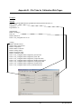
Appendix B – File Tabs for Calibration Web Pages................................................................... B-1
Addendum
What is Web_BSI?
W hat is W eb_BSI?
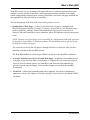
Web_BSI consists of a set of standard web pages and ActiveX controls which may be used to
configure a newly installed ControlWave series process automation controller, or to modify
certain configuration parameters in an existing ControlWave unit. Some web page functions are
also supported for Network 3000-series controllers.
The key components of the Web_BSI, from a user's point of view are:
• Standard Set of Web Pages - A series of data collection web pages, compatible with
Microsoft® Internet Explorer (Version 5.0 or newer), are provided to view data from arrays,
archives, audit files, and lists. Some of the standard web pages may be used with both
Network 3000 and ControlWave series controllers, others will function with only one product
series.
NOTE: Separate sets of web pages are also available for configuration/calibration operations
for particular ControlWave or TeleFlow products. For information on these, please consult
the help files in those web pages.
The easiest way to access the web pages is through LocalView or NetView, after you have
added the controller to the OpenBSI network.
The Web_BSI standard set of web pages (HTML) are stored on the OpenBSI workstation.
•
ActiveX Controls for use in User-Created Web Pages - In addition to this standard set of
web pages, users can create their own web pages. To support the user-created web pages, a
series of ActiveX controls specific to ControlWave and Network 3000 controllers are
provided for web page developers. User-created web pages are stored on the OpenBSI
Workstation.
•
LocalView - Allows local communication with a controller. Also allows configuration
parameters to be set. See Chapter 5 of the the OpenBSI Utilities Manual (document# D5081)
for details.
1
Web_BSI Manual
Setting up the Web_BSI Software
Setting up the W eb_BSI Software
Installing the Web_BSI software on your PC
Web_BSI is automatically included when you install either the OpenBSI Network Edition, or the
OpenBSI Local Edition. See Chapter 2 of the OpenBSI Utilities Manual (document# D5081) for
details.
IMPORTANT
The Web_BSI software should only be run on Windows™ 2008 Server, Windows™
XP Professional or Windows 7. Users are warned NOT to attempt to run this
software under Windows™ 95, because of unpredictable results. There is also no
support for Windows™ 98, Windows™ NT, or Windows™ 2000.
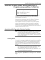
Specifying the Location of Your Web Browser
If the path of your web browser is other than the default (\Program Files\Internet Explorer\) you
will need to use a text editor to edit the WEB_BROWSER_PATH parameter in your NDF file to
reflect the web browser’s location.
WEB_BROWSER_PATH=C:\Program Files\Internet Explorer
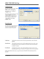
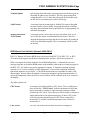
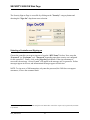
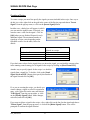
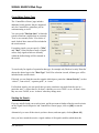
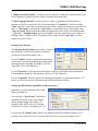
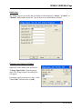
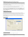
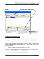
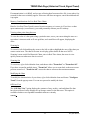
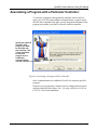
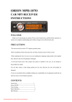
Specifying the Startup Web Page For A Controller
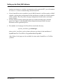
During OpenBSI system configuration, you must specify a
startup HTML web page for each controller. This can be done
in the RTU Wizard of NetView when the controller is initially
added to the network, or from the RTU Properties dialog box,
after it is already in the network.
To access the RTU Properties dialog box, right click on the
icon for the controller, and choose “Properties” from the
pop-up menu.
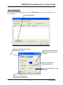
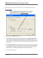
•
•
The startup web page resides on the PC workstation, so a full path and filename must be
entered in the “Startup” field of the RTU Properties dialog box.
If you would like access to the standard web page set, specify web_bsi.htm as the startup
page. This web page is referred to as the Main Menu, and contains links to all of the
standard web pages.
Web_BSI Manual
2
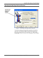
Setting up the Web_BSI Software
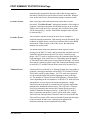
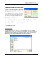
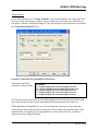
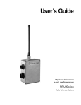
Specify the complete path and filename on the PC, of the
startup web page here. (Use the “Browse” push button to
locate the web page, if desired.)
Other Notes About Using Web Pages
• For optimum results, screen resolution should be set to 1024 x 768 when using our web
pages.
•
You can use the tab key to move between fields on web pages. (OpenBSI 5.8 and newer.)
•
If you need to enter a value in a field on a web page, you must press the [Enter] key to save
the value. You can use the [Esc] key to leave the field unchanged.
•
If you need make a selection from a drop-down menu (combo box), you must press the
[Enter] key to save the value, unless you have OpenBSI 5.8 Service Pack 1 or newer in
which case your selection is sent to the RTU automatically.
•
You can have multiple web pages open simultaneously, for example, to look at different
types of data from the same RTU. To do this, just open a new instance of Internet Explorer
(or open a new window in IE using the FileNew command). Note, however, that if you
3
Web_BSI Manual
Setting up the Web_BSI Software
terminate one instance (or window) communicating with a particular RTU, you will terminate
all instances or windows communicating with that same RTU.
•
•
•
If your ControlWave-series controller is part of a BSAP network, it will be treated as a BSAP
controller; and only those configuration facilities and features available for a BSAP controller
will be available. This will prevent web page configuration of Audit/Archive and certain
security features.
NetView software must be registered in order to be used beyond the 60 day evaluation
period. See Chapter 2 of the OpenBSI Utilities Manual (document# D5081) for more
information on the registration process.
The standard set of web pages for Web_BSI are stored in the directory:
\openbsi_installation_path\WebPages
where openbsi_installation_path is whatever directory you chose for the installation of
OpenBSI data files. The default is \ProgramData\Bristol\OpenBSI\.
Other folders of web pages are also available for various other ControlWave or TeleFlow
products.
Web_BSI Manual
4
Calling up Web_BSI Pages
Web_BSI Pages
There are two different methods for calling up the Web_BSI web pages:
IMPORTANT
If this is the first time you are calling up the Web_BSI web pages, you will need to use
the Node Locator page, described later in this manual, to identify the nodes with which
you want to communicate. After that, you should not need to use it again, unless you are
communicating with different nodes, or if your network configuration has changed.
IMPORTANT
You must log in with Administrative privileges in order to use certain configuration
web pages, in particular the Node Locator.
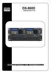
Method 1
With NetView or LocalView running, click as follows:
StartProgramsOpenBSI ToolsWeb Page AccessStandard Pages
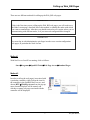
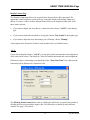
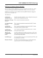
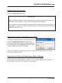
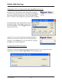
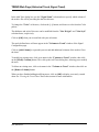
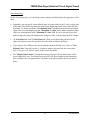
Method 2
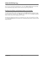
In order to call up the web page(s) associated with
a particular controller, right click on the icon for
the controller in the OpenBSI NetView tree, and
choose RTUWebPage Access from the pop-up
menu. Internet Explorer will be started, and
whichever startup web page associated with the
controller will be displayed.
5
Web_BSI Manual
Calling up Web_BSI Pages
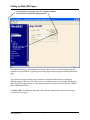
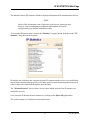
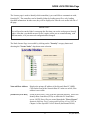
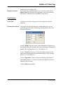
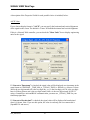
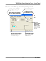
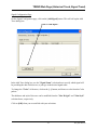
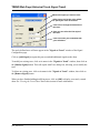
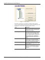
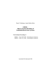
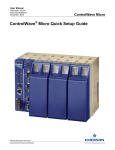
To call up other web pages, click on a category, and then
select from the choices that appear below it.
The Main Menu page in the standard set is shown, above, however, the startup page for your
controller may be different. Typically, the Security Sign-On always appears on the Main Menu
page.
The various web pages include category buttons along the left hand side, for calling up
additional pages; when you click your cursor on a category button, a list of pages belonging in
that category will appear below it. The category buttons are named Security, Statistics, Signal
Data, and Historical Data.
A “Node Name” field displays the name of the current controller from which data is being
viewed on the web page.
.
Web_BSI Manual
6
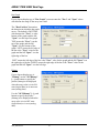
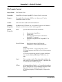
ALARM SUMMARY Web Page
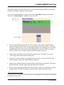
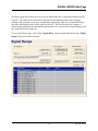
Alarm Summary W eb Page
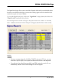
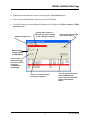
The Alarm Summary Web Page allows you to view all current alarm messages received from a
controller (or multiple controllers) in the network. 1
To access the Alarm Summary web page, click on the "Signal Data" category button, then
choose the "Alarm Summary" drop-down menu selection.
•
The most recent alarms appear at the top of the window; older alarms are automatically
moved towards the bottom. If there are more alarms than can fit in the window, a scroll bar
will appear, which you can use to view the additional alarms. By clicking on the ‘Date/Time’
column heading, you can sort alarms already displayed from newest to oldest, or oldest to
newest, however, any new alarms coming in will always appear at the top.
•
Alarms appear in different colors based on the Alarm Priority. The colors are set in the
‘Colors’ page of the Alarm Properties dialog box.
•
The choice of which columns are included for the alarm entries can be specified from the
‘Alarm Summary’ page of the Alarm Properties dialog box.
•
Alarms can be filtered so that only alarms meeting certain criteria are displayed. This can be
specified from the ‘Filtering’ page of the Alarm Properties dialog box.
•
Alarms can be sorted alphabetically based on a particular column, by clicking on the column
heading. (NOTE: This does not apply to certain columns, such as the value or limit.)
1
The initial release of the Alarm Summary Control in Version 5.3 only supported alarms from RTUs communicating
via BSAP. Beginning with OpenBSI 5.4, alarms from RTUs communicating via IP are also supported, provided the
RTU firmware is 4.40 or newer.
7
Web_BSI Manual
ALARM SUMMARY Web Page
•
Optionally, alarms can also be saved in a log file, for viewing at a later time. This can be
configured from the ‘Logging’ page of the Alarm Properties dialog box.
•
If you want to view alarms from more than one controller in the Alarm Summary, you must
be logged onto each of these controllers, prior to opening the Alarm Summary web page.
(This could be accomplished via the Sign On control, or via a login script in your web page
which uses the Sign On Control). To view a list of which controllers you are currently logged
onto, right click outside of the Alarm Summary window, but within the boundaries of the
control, and click on “Rtu List” in the pop-up menu
Acknowleging Alarms
To acknowlege an alarm visible in the Alarm Summary, click on the timestamp for the alarm,
then right-click outside of the Alarm Summary window, but within the boundaries of the control,
and click on “Ack” in the pop-up menu. If you want to select multiple alarms for
acknowlegement, hold down the [Ctrl] key as you select the alarms, then click on “Ack”. If you
want to acknowlege all alarms in the control, click on “Ack All”. NOTE: Once an alarm has
returned to normal, and has been acknowleged by the operator, it will be removed from the
alarm summary. Change of state alarms are removed once they are acknowledged.
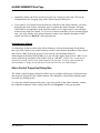
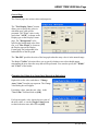
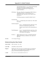
Alarm Control Properties Dialog Box
The Alarm Control Properties dialog box allows you to configure which types of alarm message
data should be displayed in the Alarm Summary. The dialog box is divided into multiple pages,
accessible by clicking on tabs.
To call up the Alarm Properties dialog box, right-click outside of the Alarm Summary window,
but within the boundaries of the control, and click on “Properties” in the pop-up menu.
Web_BSI Manual
8
ALARM SUMMARY Web Page
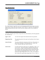
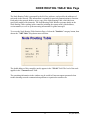
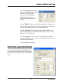
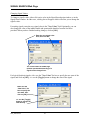
Alarm Summary Page
The ‘Alarm Summary’ page allows you to specify what parts of the alarm message you want to
display in the columns of the Alarm Summary. NOTE The RTU’s node name, the signal name,
and the timestamp when the alarm occurred are always displayed, and so are not included as
options.
Columns Which May be Included in the Alarm Summary:
To include a particular type of alarm message data in the Alarm Summary, check the appropriate
box. The boxes are:
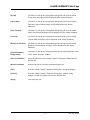
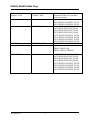
Signal’s Value
The value of the signal at the moment the alarm was generated.
Engineering Units
The engineering units for the signal, such as gallons, inches, degrees
celsius, etc.
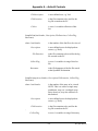
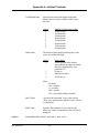
Alarm’s Priority
The priority indicates the importance of the alarm. The priorities, in
order of most importance to least importance are: Critical, NonCritical, Operator Guide (Op. Guide), and Event.
Alarm’s State
For analog alarms the possible states are ‘High-High’, ‘High’, ‘Low’
and ‘Low-Low’. These states indicate which alarm limit has been
most recently exceeded. For logical alarms, the state indicates the
type of boolean value change which occurred to generate the alarm.
‘True’ indicates the signal changed from ‘False’ to ‘True’. ‘False’
indicates the signal changed from ‘True’ to ‘False’, and ‘Change of
State’ indicates the signal simply changed from ‘True’ to ‘False’ or
9
Web_BSI Manual
ALARM SUMMARY Web Page
‘False’ to ‘True’.
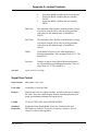
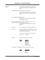
Report Type
The report type indicates the number of times the signal has gone into
an alarm condition as part of this particular alarm message. ‘Single’
indicates it went ‘in alarm’ once. ‘Momentary’ indicates that it
momentarily went ‘in alarm’, but then returned to normal. ‘Multiple’
indicates that the signal has gone into and out of alarm more than
once.
Limit Exceeded
This is the alarm limit which was exceeded.
Ack State
This shows whether the alarm has been acknowleged by the operator,
or not.
Descriptor
This is the textual descriptor of the alarm signal.
Global Sequence
Number
The Global Sequence Number of the alarm, used internally, for
identifying alarm, audit, and archive files, within this RTU.
Local Sequence
Number
The Local Sequence Number, used internally, for identifying alarms
within this RTU.
Signal’s Index
For Network 3000: The Master Signal Directory (MSD) Address. For
ControlWave: The PDD Index. These are internal numbers used by
the firmware.
Global Address
The global address of this RTU.
Load Version
The version of the ACCOL load or ControlWave project executing in
this RTU.
Push Buttons and Other Controls
[Select All]
Selects all items for inclusion as columns in the Alarm Summary.
Users can then de-select any they do not want.
[Clear All]
Clears all selections on this page.
[Save As Defaults]
Saves the selections in the Alarm Control’s Properties dialog box to a
defaults file.
[Restore Defaults]
Restores the saved selections from the defaults file.
[OK]
Exits the Alarm Control’s Properties dialog box, saving all changes.
Web_BSI Manual
10
ALARM SUMMARY Web Page
[Cancel]
Exits the Alarm Control’s Properties dialog box, without saving
changes, except for changes saved to the defaults file.
[Help]
Calls up a help file.
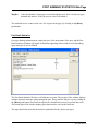
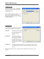
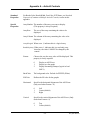
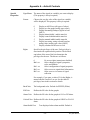
Filtering Page
Sometimes, the user may wish to limit the alarm summary to only signals which satisfy certain
criteria, for example, they may want to exclude ‘Event’ and ‘Op. Guide’ alarms so that the
summary only shows ‘Critical’ and ‘Non-Critical’ alarms, or they may want to exclude ‘Logical
Alarms’ so that the summary will only show ‘Analog Alarms’. The Filtering page allows users to
specify this filtering criteria.
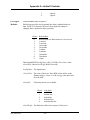
Exclude Alarm Type
This allows you to limit the alarm summary to only analog alarms, or
only logical alarms.
Selecting “Analog Alarms” prevents display of analog alarms in the
Alarm Summary.
Selecting “Logical Alarms” prevents display of logical (BOOL) alarms
in the Alarm Summary.
The contents of the Alarm Summary can be saved in an alarm snapshot
Apply Filtering
while in offline mode (*.ALM) file, for off-line viewing, even when communications are not
active with the RTU network. If, when viewing the off-line alarm
summary, you want to continue to filter alarms, based on the criteria
11
Web_BSI Manual
ALARM SUMMARY Web Page
defined on this page, select the “Apply Filtering while in offline
mode” box.
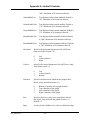
Exclude Priority
This allows you to limit the priorities of alarms which are displayed in
the Alarm Summary.
Selecting “Event” prevents display of event priority alarms in the
Alarm Summary.
Selecting “Op. Guide” prevents display of operator guide alarms in the
Alarm Summary.
Selecting “Non-Critical” prevents display of non-critical alarms in the
Alarm Summary.
Selecting “Critical” prevents display of critical alarms in the Alarm
Summary.
Exclude Limit
This allows you to restrict analog alarms which are displayed in the
Alarm Summary based on which alarm limits have been exceeded, for
example, you could exclude low and high alarms, and only show lowlow and high-high alarms in the Alarm Summary.
Selecting “Low” prevents display of analog alarms in the Alarm
Summary which have exceeded their low alarm limit.
Selecting “High” prevents display of analog alarms in the Alarm
Summary which have exceeded their high alarm limit.
Selecting “Low-Low” prevents display of analog alarms in the Alarm
Summary which have exceeded their low-low alarm limit.
Selecting “High-High” prevents display of analog alarms in the Alarm
Summary which have exceeded their high-high alarm limit.
Exclude Logical
Type
This allows you to restrict logical alarms which are displayed in the
Alarm Summary based on which logical state triggered the alarm.
Selecting “False” prevents alarms generated by a signal becoming
FALSE, from being displayed in the Alarm Summary.
Selecting “True” prevents alarms generated by a signal becoming
TRUE, from being displayed in the Alarm Summary.
Web_BSI Manual
12
ALARM SUMMARY Web Page
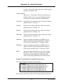
Selecting “Change of State” prevents alarms generated by a signal
changing state from FALSE-to-TRUE or TRUE-to-FALSE, from being
displayed in the Alarm Summary.
Exclude Report
This allows you to restrict alarms which are displayed in the Alarm
Summary based on how the alarms are reported.
Select “Single” to prevent alarms generated based on a signal entering
an alarm condition once from appearing in the Alarm Summary.
Select “Momentary” to prevent alarms generated based on a signal
momentarily entering an alarm condition and then returning to normal,
from appearing in the Alarm Summary.
Select “Multiple” to prevent alarms generated based on a signal
entering an alarm condition more than once for a given alarm message
from appearing in the Alarm Summary.
Push Buttons and Other Controls
[Exclude All]
Causes all boxes on the Filtering page to be selected, thus excluding all
alarms from the Alarm Summary.
[Include All]
Clears all boxes on the Filtering page, thereby turning off filtering, and
allowing all alarms to be displayed in the Alarm Summary.
[Save As Defaults]
Saves the selections in the Alarm Control’s Properties dialog box to a
defaults file.
[Restore Defaults]
Restores the saved selections from the defaults file.
[OK]
Exits the Alarm Control’s Properties dialog box, saving all changes.
[Cancel]
Exits the Alarm Control’s Properties dialog box, without saving
changes, except for changes saved to the defaults file.
[Help]
Calls up a help file.
13
Web_BSI Manual
ALARM SUMMARY Web Page
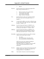
Colors Page
The Colors page allows you to choose which colors you want displayed for alarm messages of a
particular priority, for example, critical alarms appear in RED, etc. The page also lets you define
the background color for the Alarm Summary window.
How to set colors:
The current colors for each alarm priority are displayed next
to a button for that priority. To specify the colors which will
be displayed for alarm messages of a particular priority,
click on the button for that priority, and the color pallette
will appear.
Choose the desired color, and then click on [OK].
Web_BSI Manual
14
ALARM SUMMARY Web Page
[Event]
Click here to call up the color pallette and specify the color in which
Event alarm messages will be displayed in the Alarm Summary.
[Op. Guide]
Click here to call up the color pallette and specify the color in which
Operator Guide alarm messages will be displayed in the Alarm
Summary.
[Non-Critical]
Click here to call up the color pallette and specify the color in which
Non-Critical alarm messages will be displayed in the Alarm Summary.
[Critical]
Click here to call up the color pallette and specify the color in which
Critical alarm messages will be displayed in the Alarm Summary.
[Return-to-Normal]
Click here to call up the color pallette and specify the color in which
Return-to-Normal alarm messages will be displayed in the Alarm
Summary.
[Alarm Summary
Background]
Click here to call up the color pallette and specify the background color
of the Alarm Summary window.
[Save As Defaults]
Saves the selections in the Alarm Control’s Properties dialog box to a
defaults file.
[Restore Defaults]
Restores the saved selections from the defaults file.
[OK]
Exits the Alarm Control’s Properties dialog box, saving all changes.
[Cancel]
Exits the Alarm Control’s Properties dialog box, without saving
changes, except for changes saved to the defaults file.
[Help]
Calls up a help file.
15
Web_BSI Manual
ALARM SUMMARY Web Page
Logging Page
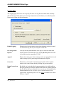
The Logging page allows the user to specify the name of a log file into which alarm summary
data will be stored. This allows users to keep a historical record of alarms, even after they have
been removed from the Alarm Summary.
Enable Logging
When checked, causes entries in the Alarm Summary to also be stored
in a ASCII-text log file on your computer’s hard disk.
File to log Alarm
Reports
This specifies the path and name of the log file where the alarm data
will be stored. If a file already exists, use the [Browse] button to locate
it. Log files have the extension of *.LOG.
Append
When selected, any new alarm summary entries are appended to the end
of the existing log file, preserving earlier data in the log file.
Overwrite
When this is selected, the Alarm Summary log file will be emptied
whenever the control starts, thereby deleting any previous entries.
Dump Extra alarm
data
By default, the local and global sequence numbers, the global address,
the load version, the descriptor, and the PDD index are omitted from the
log file. When this box is selected, however, they are all included in the
Alarm Summary log file. All other types of Alarm Summary Data
(signal value, engineering units, etc.) are always included in the Alarm
Summary Log file.
Web_BSI Manual
16
ALARM SUMMARY Web Page
Apply filtering while
logging
When selected, filtering criteria specified in the ‘Filtering’ page of the
Alarm Properties dialog box, will be used to limit the types of alarms
stored in the Alarm Summary Log file. When this is not selected,
filtering criteria will only apply to the alarms appearing on the screen in
the Alarm Summary.
[Save As Defaults]
Saves the selections in the Alarm Control’s Properties dialog box to a
defaults file.
[Restore Defaults]
Restores the saved selections from the defaults file.
[OK]
Exits the Alarm Control’s Properties dialog box, saving all changes.
[Cancel]
Exits the Alarm Control’s Properties dialog box, without saving
changes, except for changes saved to the defaults file.
[Help]
Calls up a help file.
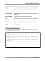
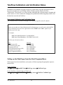
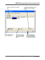
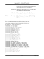
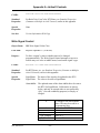
Example of an Alarm Summary Log File:
An example of an Alarm Summary Log File is shown below. These files may be viewed in
Notepad or any other ASCII text editor.
23-JAN-2004 13:43:00.560
Critical Single
Portland
LOOP7.INP.
0.000000 PSIA
23-JAN-2004 13:43:00.560
Critical Single
Portland
LOOP8.INP.
0.000000 RPM
23-JAN-2004 13:43:06.580
Non-Critical
Portland
LOOP8.INP.
6.000000 RPM
23-JAN-2004 13:43:11.560
Critical
Portland
LOOP7.INP.
11.000000 PSIA
23-JAN-2004 13:43:16.560
(Normal)
Portland
LOOP8.INP.
16.000000 RPM
17
Web_BSI Manual
ALARM SUMMARY Web Page
Saving a ‘snapshot’ of the current alarms into an Alarm Snapshot File
An Alarm Snapshot File is different from the Alarm Summary Log File discussed, earlier. Alarm
Snapshot Files have a file extension of (*.ALM) and are used to store a ‘snapshot’ of all current
alarms visible in the Alarm Summary. They are binary files, and so cannot be viewed in a text
editor.
To save the current alarms appearing on the screen in an existing Alarm Snapshot file, right-click
outside of the Alarm Summary window, but within the boundaries of the control, and click on
“Save” in the pop-up menu. If there is no existing Alarm Snapshot file, you will be prompted for
a path and filename, for the Alarm snapshot file.
If you store the Alarm data in an all new snapshot file, choose “Save As” instead of save, and
provide the path and filename for the file.
Viewing an Alarm Snapshot File
An Alarm Snapshot file can only be viewed when the Alarm Summary Window is in off-line
mode.
To view the snapshot file, right-click outside of the Alarm Summary window, but within the
boundaries of the control, and click on “Open”, then navigate to the alarm snapshot (*.ALM)
file, and open the file. The Alarm Summary Window will automatically go off-line, and no new
alarms will be displayed or logged while it is off-line. (You can tell the Alarm Summary is offline because while in off-line mode, the word OFFLINE appears on a status line at the bottom of
the window, along with the path and name of the Alarm Snapshot file currently being viewed.)
When you have finished viewing the Alarm Snapshot file, you can close it and return to on-line
mode by right-clicking outside of the Alarm Summary window, but within the boundaries of the
control, and then clicking on “Online”. The Alarm Summary control will now resume displaying
active alarms.
Web_BSI Manual
18
ARCHIVE COLLECTION Web Page
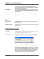
Archive Collection Web Page
The Archive Collection page allows you to view the contents of archive files stored in the
controller.
To access the Archive Collection page, click on the "Historical Data" category button, then
choose the "Archive Collection" drop-down menu selection.
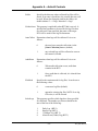
Archive Collection Parameters
Collect by Name
If the type of controller you are communicating with supports access
to Archive files using the Archive file's name, you can check this
box, and then enter the desired archive file's name in the "File
Name" field. Otherwise, you must access the file through its file
number.
Start from oldest record
If you would like the oldest archive file entries to appear first, select
this option.
Freeze Date/Time
As you scroll through the archive file window, the first column
19
Web_BSI Manual
ARCHIVE COLLECTION Web Page
File Number
File Name
Stats
Fields Collected
Records Collected
(which may contain date/time stamps) may disappear from the
window as higher numbered columns are brought into the window.
To prevent this, select this option.
This is the unique ID number for the Archive File you want to view.
To enter the file number, the "Collect by Name" check box must
NOT be selected.
This is the archive file name of the Archive File you want to view.
To enter the archive file name, you must have checked the "Collect
by Name" box.
Displays the number of fields (columns) in the archive file which
have been collected.
Displays the number of records (rows) in the archive file which have
been collected.
Push Buttons and Other Controls
Collect Data
Click on this button to collect archive data based on your entries in
the "Archive Collection Parameters" section.
Save Parameters
This button calls up the Save Parameters dialog box. You can save
the archive data you have viewed into a file on your PC hard disk.
To save the archive data, check the "Save Archive Data" check
box, then enter a filename in the "Filename" field, or choose the
[…] button to locate a path and filename of a file. NOTE: This only
saves a snapshot of the data you have actually viewed on the screen;
it does NOT save the entire archive file. As you scroll to bring new
data on the screen, it will be added to the specified file. If you want
to save an entire Archive File, you should use a tool such as the
OpenBSI Harvester or the Historical Log Storage control.
Web_BSI Manual
20
ARCHIVE COLLECTION Web Page
Click on [OK] when finished.
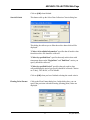
Search Criteria
This button calls up the Select Data Collection Criteria dialog box.
This dialog box allows you to filter the archive data which will be
displayed.
"Collect All Available Information" specifies that all archive data
from this archive file should be collected.
"Collect by specified Date" specifies that only archive data with
timestamps between the "Begin Date" and "End Date" entries you
specify should be collected.
"Collect by specified Period" specifies that only archive data
collected during the period you specify should be collected. Choices
are 'Today', 'This Week', or 'This Month'.
Click on [OK] when you have finished selecting the search criteria.
Floating Point Format
Calls up the Float Format dialog box. In this dialog box, you can
specify the precision with which analog (floating point) values are
displayed.
21
Web_BSI Manual
ARCHIVE COLLECTION Web Page
Use the "Width" list box to specify the total number of characters
in the field (including the decimal point) when displaying a floating
point number. This can range from 1 to 15. The default is 12.
Use the "Precision" list box to choose the number of places to the
right of the decimal point which should be displayed. This can range
from 0 to 15. The default is 6.
Use the "Exponent" list box to choose the floating point format 'f',
exponential notation 'e', or choose 'g' to have the Archive Collection
control choose the best fit format.
Click on [OK] when finished.
File Definition
Web_BSI Manual
This button displays certain configuration parameters for this archive
file, e.g. number of records. NOTE: These parameters CANNOT be
changed here, they are only displayed.
22
ARRAY COLLECTION Web Page
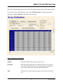
Array Collection W eb Page
The Array Collection Page allows you to view the contents of data arrays stored in the controller.
To access the Array Collection page, click on the "Historical Data" category button, then
choose the "Array Collection" drop-down menu selection.
Array Collection Parameters
Number
Enter the number of the array you want to view.
Start Row
Enter the number of the first row of data in the array you want to
view. This is useful in the case of very large arrays, in which you
want to skip earlier rows, and start with a particular row.
Type
This list box is used to choose the type of array to be viewed (real,
etc.)
23
Web_BSI Manual
ARRAY COLLECTION Web Page
Array Info
Rows
This displays the total number of rows in this array.
Columns
This displays the total number of columns in this array.
Rows Collected
This displays the number of rows which have been collected for
display in the current window.
Read, Read/Write
This indicates the array access type. Read means this is a read-only
array; read/write means it is a read/write array.
Push Buttons and Other Controls
Load Array
Click on this button to view the array specified based on your entries
in the "Array Collection Parameters" section.
Save Parameters
This button calls up the Write Array Collection dialog box. You can
save the array data you have viewed into a file on your PC hard disk.
To save the array data, enter a filename in the "Filename" field, or
choose the […] button to locate a path and filename of a file.
NOTE: This only saves a snapshot of the data you have actually
viewed on the screen; it does NOT save the entire array. As you
scroll to bring new data on the screen, it will be added to the
specified file.
If you want to save the entire array, enter a "Start Row" of 1, and
check the "Collect All" box.
If you want to only save certain rows of the array, make sure
"Collect All" is not selected, and choose a starting row in "Start
Row", and enter the total number of rows (beginning with the
starting row) that you want to store in the "Max # of Rows to
Web_BSI Manual
24
ARRAY COLLECTION Web Page
Write" field.
Click on [OK] when finished.
Floating Point Format
Calls up the Float Format dialog box. In this dialog box, you can
specify the precision with which analog (floating point) values are
displayed.
Use the "Width" list box to specify the total number of characters
in the field (including the decimal point) when displaying a floating
point number. This can range from 1 to 15. The default is 12.
Use the "Precision" list box to choose the number of places to the
right of the decimal point which should be displayed. This can range
from 0 to 15. The default is 6.
Use the "Exponent" list box to choose the floating point format 'f',
exponential notation 'e', or choose 'g' to have the Array Collection
control choose the best fit format.
Click on [OK] when finished.
25
Web_BSI Manual
ARRAY COLLECTION Web Page
Freeze First Column
As you scroll through the array window, the first column (which
may contain date/time stamps) may disappear from the window as
higher numbered columns are brought into the window. To prevent
this, select this option.
View First Column as
Date / Time
Depending upon how your data array is configured, it may include a
numerical total used by the system to store the date / time, instead of
the Julian date / time stamp. Use this button to toggle between the
two formats.
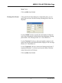
Changing Array Values
If desired, you can change the value of individual
elements in the data array. To do so, click on the
element you want to change, enter the new value in
the Change Value dialog box, and click on [OK].
Web_BSI Manual
26
ARRAY ITEM VIEW Web Page
Array Item View Web Page
The Array Item View page allows the value of a specific array cell to be displayed on the screen.
In order to successfully use this page, you must have already signed on to the controller which
contains the array you want to display.
To access the Array Item page, click on the "Historical Data" category button, then choose the
"Array Item View" drop-down menu selection.
Configuring the Array Item View Control
If a signal has not been configured, already, the Array Item View Control will present a series of
question marks on the screen '?????'.
Right-click on the question marks, and choose "Configure Array" from the pop-up menu. The
Configuration page of the Configure Array dialog box will appear:
NOTE: The Configure Array dialog box contains multiple pages. The dialog box displays the
number of the array you configure in the title bar. To move between the various pages,
click on the tab for that page. Clicking on [OK] in any of the pages will exit the dialog
box, therefore, you should only click on [OK] when you have finished with all of the
necessary pages. Clicking on [Reset] erases your entries, and replaces them with
defaults.
27
Web_BSI Manual
ARRAY ITEM VIEW Web Page
Configuration Page
Select the controller from the "Node
Name" list box. Then specify
whether this is an "Analog" or
"Logical" array.
Specify the number of the array in the
"Array Number" field. Then,
identify which cell of the array you
want to display by filling in the
"Array Row" and "Array
Column" fields.
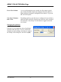
Refresh Rate Page
The Refresh Rate page specifies how
often data will be updated on the
screen for an item of array data.
No Refresh
'No Refresh' means the value will only be presented once, and will not be
updated.
Slow Refresh
'Slow Refresh' means the value will be updated at the slow rate; this varies
depending upon the type of controller, for Network 3000 series nodes this
would be 5 seconds.
Fast Refresh
'Fast Refresh' means the value will be updated at the fast rate; this varies
depending upon the type of controller. The update will be as fast as possible.
NOTE: The default refresh rates are specified in the DATASERV.INI initialization file for
OpenBSI.
Web_BSI Manual
28
ARRAY ITEM VIEW Web Page
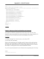
Display Format Page
The Display Format page allows you to specify how the array data will be presented. The
appearance of the 'Properties' section will vary, somewhat, based on the display format you
choose. You have a choice of three different items which can be displayed. Only ONE of the
three can be selected:
•
If you want to display the array data as a numerical value, choose "ASCII" as the display
type.
•
If, you want to depict the array data as a bar graph, choose "Bar Graph"as the display type.
•
If you want to depict the array data using a pair of bitmaps, choose "Bitmap".
A description of the 'Properties' fields for each possible choice is included, below:
ASCII:
If your chosen display format is "ASCII" you can specify the horizontal and vertical alignment
of the value on the screen. The default is 'Center' for both the horizontal and vertical alignment.
If this array value is a timestamp, you should check the "Show Date Time" box; otherwise the
timestamp will be displayed as a numerical value.
The [Floating Point Format] button calls up a dialog box which lets you specify the number of
decimal places used to present the signal value. This dialog box is shared by many different
controls. See page 91 for details.
29
Web_BSI Manual
ARRAY ITEM VIEW Web Page
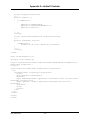
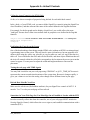
Bar Graph
If your chosen display type is "Bar Graph" you must enter the "Zero" and "Span" values
which define the range of the array item value.
The "Base Position" determines
the direction in which the bar graph
moves. The default is 'BOTTOM',
which means the "Zero" is at the
bottom of the graph, and the full
"Span" is at the top of the graph.
'TOP' means the "Zero" is at the
top of the graph, and the full
"Span" is at the bottom of the
graph. 'LEFT' means the left edge of
the bar is the "Zero" value for the
graph and the full "Span" is at the
right edge of the bar.
'LEFT' means the left edge of the bar is the "Zero" value for the graph and the full "Span" is at
the right edge of the bar. 'RIGHT' means the right edge of the bar is the "Zero" value for the
graph and the full "Span" is at the left edge.
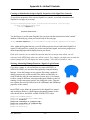
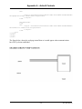
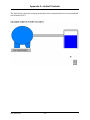
Bitmap
If your chosen display type is
"Bitmap" use the "ON Bitmap"
[…] push button to specify the
picture (bitmap) to be displayed
when the array value is in its ON
state (logical data) or its non-zero
state (analog data).
Use the "OFF Bitmap" […] push
button to specify the picture
(bitmap) to be displayed when the
array value is in its OFF state
(logical data) or is zero (analog
data).
Web_BSI Manual
30
ARRAY ITEM VIEW Web Page
General Page
The General page sets various colors and properties.
The "Text Display Colors" section
allows you to specify the colors in
which the array value will be
presented. The "Text" color is only
used when "ASCII" is chosen as the
Display type on the Display Format
page. The "Background" color
specifies the background color of the
text, or if "Bar Graph" is chosen as
the Display type on the Display
Format page, the background color
behind the bar of the bar graph.
The "Bar Fill" specifies the color of the bar graph when the array value is in the normal range.
The Border"Visible" selection allows you to specify whether or not a box should appear
surrounding the area where the array data will be presented. You can also specify the "Width"
and "Color" of the border.
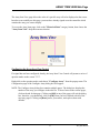
Changing the Value of an Array Item (through a dialog box)
Right-click on the value, and choose "Change
Array Value" from the pop-up menu. The Change
Value dialog box will appear.
For analog values, enter the new value, in the
"New Value" field and click on [OK].
For logical signals, either choose the new state of
the array value, or use the [Toggle Value] button
to choose the new state, then click on [OK].
31
Web_BSI Manual
ARRAY ITEM VIEW Web Page
Changing the Value of an Array Item (in-line edit) (OpenBSI 5.8 and newer)
An alternative to changing the value in a dialog box is to
click on the array value. This opens an in-line change
box around the value. You can then type in the new
value and press the [Enter] key on the keyboard to send
the new value to the array in the RTU. To exit the in-line
change box, press the escape key [Esc].
Verifying That Communications Are Possible to the Array
Right-click on the array value, and choose "Show Array Status" from the pop-up menu. The
Array Status dialog box will appear. 'Success' will be displayed if the signal can be accessed;
otherwise an error message will appear. Click on [OK] to exit the dialog box.
Web_BSI Manual
32
AUDIT COLLECTION Web Page
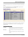
Audit Collection Web Page
The Audit Collection Page allows you to view the contents of the alarm and event buffers in the
controller.
To access the Audit Collection page, click on the "Historical Data" category button, then
choose the "Audit Collection" drop-down menu selection.
NOTE: Any audit entries which have already been collected from a controller via the Historical
Log Storage control, or the OpenBSI Harvester, will NOT be accessible through the Audit
Collection web page.
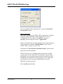
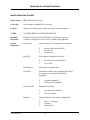
Push Buttons and Other Controls
Collect Data
Click on this button to collect audit data based on your entries in
the Data Storage Parameters and Search Criteria dialog boxes.
Data Storage
Click on this button to call up the Data Storage Parameters dialog
boxes.
You can save the audit data you have viewed into a file on your PC
hard disk.
33
Web_BSI Manual
AUDIT COLLECTION Web Page
To save a snapshot of the audit data, first, select the “Store Data
on Collection” option.
Storage Parameters:
Next, enter a filename in the "File" field, or choose the […] button
to specify a path and filename of the snapshot file. If you are
creating an all-new file, choose "Create File"; if you are
appending to an existing file, choose "Append File".
Choose a format for the way the audit data entries will be separated
in the snapshot file using the "Data Delimiter" field. Choices
include a space, comma, or semi-colon.
Selecting the “Convert Data to Extended Format” option stores a
longer version of the audit data.
NOTE: This only saves a snapshot of the data you have actually
viewed on the screen; it does NOT save the entire contents of the
audit buffers. As you scroll to bring new data on the screen, it will
be added to the specified file. If you want to save ALL Audit data,
you should use a tool such as the OpenBSI Harvester or the
Historical Log Storage control.
Click on [OK] when finished.
Web_BSI Manual
34
AUDIT COLLECTION Web Page
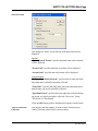
Search Criteria
This dialog box allows you to filter the audit data which will be
displayed.
Records:
“Both Alarms & Events” specifies that both alarm and event data
will be displayed
“Events Only” specifies that only event data will be displayed.
“Alarms Only” specifies that only alarms will be displayed.
Search Method:
"Collect All Available Records" specifies that all audit data from
this alarm and event buffer should be collected.
"Start Date" specifies that only audit data with timestamps newer
than the date you specify should be collected.
"Specified Period:" specifies that only audit data collected during
the period you specify should be collected. Choices are 'Today',
'This Week', or 'This Month'.
Click on [OK] when you have finished selecting the search criteria.
Total # of Records
Collected
This displays the total number of audit records collected by the
Audit Collection control for the current window.
uffer Usage Web Page (Network 3000)
35
Web_BSI Manual
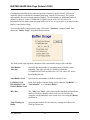
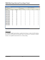
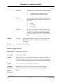
BUFFER USAGE Web Page (Network 3000)
Communication buffers are pre-allocated portions of memory, in the Network 3000-series
controller, that are used to hold communication input / output (I/O) messages. The system
automatically allocates a certain number of buffers. The total number of additional buffers is
defined, by the user, in the *COMMUNICATIONS section of the ACCOL source file.
Information on how many communication buffers are in use, at a given time, is presented on the
Buffer Usage Statistics Page.
To access the Buffer Usage Statistics page, click on the "Statistics" category button, then
choose the "Buffer Usage" drop-down menu selection.
The fields on the page represent a snapshot of the current buffer usage in the controller:
Total Buffers
Allocated
represents the total number of communication I/O buffers in the
controller. This value can only be altered by editing the
*COMMUNICATIONS section of the ACCOL source file, and redownloading the unit.
Total Buffers Used
represents the total number of buffers currently in use.
Up Buffers Used,
Down Buffers Used,
Generic Buffers Used
Each of the buffers currently being used is either an "Up Buffer", a
"Down Buffer", or a "Generic Buffer".
Min, Max
The "Min" and "Max" values represent the minimum and maximum
number of buffers which have been used since the last time the
controller was downloaded, or the counts were reset using the [Reset]
push button.
Tasks Waiting for
Buffer
represents the number of tasks which are waiting for buffers to be
freed-up for their use.
Web_BSI Manual
36
BUFFER USAGE Web Page (Network 3000)
Indications of Buffer Shortages
If the "Total Buffers Used" is consistently close to the "Total Buffers Allocated" value, there
are probably not enough buffers allocated.
Similarly, if the "Task Waiting for Buffers" is frequently a non-zero value, more buffers may
need to be allocated.
Edit the number of Communication I/O Buffers defined in the *COMMUNICATIONS section
of the ACCOL Load, and re-download the Network 3000 unit.
Resetting the Min, Max Counts
The count of the "Min" and "Max" buffers used can be reset to 0 by clicking on the [Reset] push
button. You must be signed on with sufficient security privileges in order to perform the reset.
37
Web_BSI Manual
CRASH BLOCKS Web Page
Crash Blocks W eb Page
A crash block is an area of memory in the controller which retains a 'snapshot' of the state of the
unit immediately prior to a system failure. This information can be used by Emerson Application
Support and/or Development personnel to help diagnose the cause of the failure. NOTE: Not all
failures result in useable crash block information.
To access the Crash Block Statistics page, click on the "Statistics" category button, then choose
the "Crash Blocks" drop-down menu selection.
The contents of the crash block should be recorded and provided to Emerson personnel for
analysis. (You can copy the screen to the Windows™ Clipboard by the Windows™
[Alt][Printscreen] command, and then paste it into another document, which can then be
printed.) Once this has been done, all five of the crash blocks can be cleared (by clicking on the
[Reset] push button) to allow any new crash information to be captured.
Web_BSI Manual
38
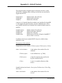
CUSTOM PROM INFO Web Page (Network 3000)
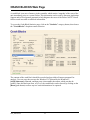
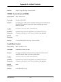
Custom PROM INFO Web Page (Network 3000)
The Custom PROM Statistics Page displays the contents of the Custom PROM area.
To access the Custom PROM Statistics page, click on the "Statistics" category button, then
choose the "Custom Prom" drop-down menu selection.
The window displays, in abbreviated form, the name of each custom communication "Protocol"
which is installed in the custom area of the controller. The number of protocols installed appears
in the "Entries" field. Use the scroll bar to view entries which do not fit in the window. The
"Mode" value is the number which must be entered in the ACCOL Custom Module to designate
which protocol is to be used. Users can find the mode values for the most popular protocols, and
configuration information for those protocols, in the ACCOL II Custom Protocols Manual
(document# D4066).
"Product" is an identification string for the custom firmware, as specified in the Custom PROM
area. 'PCP' is the proper identification string for custom firmware.
"Firmware Version" provides information about the type of custom firmware, and is typically
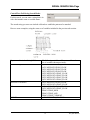
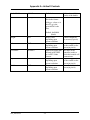
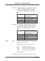
one of the following values:
3
5
7
8
firmware is 186-based pre-version AE.00
firmware is 186-based, version AE.00 through AJ.10
firmware is 186-based AK or newer or 386EX Real Mode
firmware is 386EX Protected Mode
"Link Date" and "Checksum" are the firmware link date and data checksum value. This
information can be used by Emerson personnel to verify PROM revision information.
"Prom Version" version is encoded as:
39
Web_BSI Manual
CUSTOM PROM INFO Web Page (Network 3000)
aa.bb.cc
where:
'aa' is the firmware version
'bb' is the update revision
'cc' indicates the beta revision
for example PCP00 with no updates or beta revisions would appear as 00.00.00.
Web_BSI Manual
40
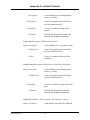
FILE TRANSFER Web Page
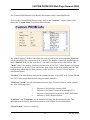
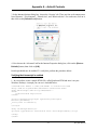
File Transfer web page
The File Transfer web page allows user files (web pages, initialization files, etc.) to be
transferred to and from the ControlWave’s FLASH memory area. NOTE: This utility is NOT
intended for downloading the ControlWave project itself, since that goes to a different area of
memory.
This control is available in OpenBSI 5.6 Service Pack 1 (and newer).
To access the File Transfer web page, choose the “Misc” category button, and then select either
“File Upload” or “File Download”.
File Download mode transfers files from the PC to the ControlWave. File Upload mode transfers
files from the ControlWave to a specified location on the PC.
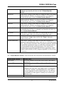
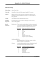
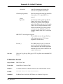
The fields are as follows:
PC File Location
In Download mode, this is the path, and filename of the file on the PC to
be downloaded to the ControlWave. In Upload mode, this is the
destination path on the PC where the file uploaded from the
ControlWave will be sent. If not set, the default OpenBSI installation
directory will be used as the location. The [Browse] button may be used
to specify the location.
41
Web_BSI Manual
FILE TRANSFER Web Page
(Upload Mode ONLY)
This is the name of the file to be transferred from the ControlWave to
the PC. Only one file can be transferred at a time.
[Start]
This starts the file transfer.
[Stop]
This aborts the file transfer. If sending to the ControlWave, any partial
file transferred will be automatically deleted from its destination. If
sending to the PC, any partial file will remain.
Device Filename
IMPORTANT
Once you have initiated a file transfer you must stay on the File Transfer page until the
transfer completes successfully. If, instead, you go to a different page before successful
completion, the transfer will be automatically aborted, and you will be prevented from
transferring that file again because it will be locked for 10 minutes.
Downloading a File from the PC to the ControlWave’s FLASH Memory
Choose “File Download” from the “Misc” item in the menu.
Use the [Browse] button to specify the path and name of the file you want to download, or type it
in directly in the “PC File Location” field.
Click on [Start] and the file will be sent to the ControlWave. The status bar will indicate when
the transfer has completed.
Uploading a File from the ControlWave’s FLASH Memory to the PC
Choose “File Upload” from the “Misc” item in the menu.
Specify the name of the file you want to transfer in the “Device Filename” field.
Specify the path on the PC where you want the file to be sent in the “PC File Location” field.
Use the [Browse] button to do this, if desired. If nothing is specified, the default OpenBSI
installation directory will be used. NOTE: If you want the destination file to have a different
name, specify the new filename at the end of the path statement, e.g:
C:\MYFILES\NEWNAME.TXT
Click on [Start] and the file will be sent from the ControlWave to the specified directory on the
PC. The status bar will indicate when the transfer has completed.
Web_BSI Manual
42
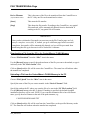
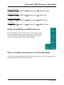
HISTORICAL LOG STORAGE Web Page
Some of our products maintain logs which may be accessed by the user. They can be stored in
files on the PC using the Historical Log Storage page. Data for these logs is extracted from the
Archive, Audit, and List files.
istorical Log Storage Web page
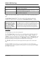
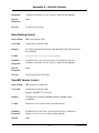
Storage Folder
This is the directory on the PC where the log files will be stored. This
directory must exist.
Log selection
window
The window in the center of the page displays details of the available data in
the RTU which can be used to create log files. Included are the "Type" of
data (audit, archive, list), a "Description" of the data, a "Log Number"
which identifies the archive file number or list number (not applicable to
audit), and an "Extension" which shows the file extension which will be
used for the log file.
This window is also used to specify which logs you want to collect, view, or
convert to CSV. To select a log, click on it. You can select multiple logs for
collection by holding down the [Ctrl] key as you select. Once you have
selected the logs, you can start the collection by clicking on [Start
Collection]. The view and convert options can only be used on one log at a
time.
43
Web_BSI Manual
HISTORICAL LOG STORAGE Web Page
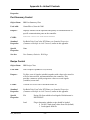
[Start Collection] When clicked will start collections of all selected logs. This button is
disabled if collections are already in progress.
[Stop Collection]
When clicked, will terminate all underway collections. Note: This can result
in incomplete data being stored in log files.
[View Storage]
When clicked, will display the contents of the currently selected log file in a
separate window on the screen.
[Convert to
CSV]
When clicked, will generate a comma separated variable (CSV) file, from
the contents of the currently selected log file(s). To select more than one log
file, hold down the [Ctrl] key (OpenBSI 5.8 and newer). This file will be
created in the folder specified in the “Storage Folder” field. The filename
will be the original file basename, followed by an underscore, followed by
the original file extension, then (.CSV) for the extension. For example, the
CSV file generated from the log file DAILY.DLY would be named
DAILY_DLY.CSV.
Status box
This displays error and status information about collections. The most recent
error/status message appears, however, you can scroll down to view
previous messages.
Web_BSI Manual
44
IP STATISTICS Web Page
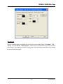
IP Statistics Web Page
The Internet Protocol (IP) Statistics Window displays information on IP communication activity.
NOTE
Much of this information is not of interest to typical users. Advanced users,
however, who are attempting to implement non-standard IP network
configurations, may find this information useful.
To access the IP Statistics page, click on the "Statistics" category button, then choose the "IP
Statistics" drop-down menu selection.
IP statistics are divided up into categories because IP communications involves several different
inter-related communication protocols. All of these protocols must function together properly in
order for data to be transferred through the network intact.
The "Selected Protocol" list box allows you to choose which portion of the IP statistics you
would like to access.
Users can reset all Internet Protocol statistics by clicking on the [Reset All] push button.
The various categories of statistics are described, below:
45
Web_BSI Manual
IP STATISTICS Web Page
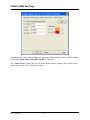
IP Statistics Decription
IP stands for Internet Protocol; it is a specification which defines the most basic packets of
information transported in a TCP/IP network. IP provides addressing and packet routing
mechanisms. The statistics maintained are as follows:
Packets Received
Number of data packets received from the Data Link. Invalid packets
and packets destined for 'pass-thru' are included in this count. Not
counted are packets discarded by the data link due to checksums or
length checks performed at that layer.
Received with Header
Error
Discards due to header errors: these include invalid IP data length,
invalid IP version, and IP header checksum errors.
Received with invalid IP Number of times which a packet was received which is not for the
current RTU and the current RTU does not know how to route the
Address
packet to the contained address.
Packets Forwarded
Number of receive packets not for the current RTU, which have been
forwarded to another machine for processing.
Received with invalid
protocol
Discards due to an unrecognized protocol code in the header.
Packets delivered
to stack
Number of packets properly received, and sent on to be processed by
a protocol handler.
Packet send attempts
Number of packets which the IP layer has been asked to send. This
includes discards. Note: This count does not include send attempts
which are discarded by UDP or other higher-level layers.
Send Packets
discarded
Packets discarded due to badly formed packets (length errors, bad
destination, etc.)
Send Packets
(No Route)
Packets discarded because there is no known route to the destination
address. Also, increments the `discarded' statistic.
Packet Fragments
received
A data link does not support sending of an entire large packet in one
section; therefore, the source machine has broken it into fragments.
This is the total number of these fragments received.
Packets assembled from
fragments
The number of packets which have been put together from
fragments.
Web_BSI Manual
46
IP STATISTICS Web Page
Reassembly of packet
failed
The number of times a packet has been discarded due to not
receiving all of its fragments within the allotted time.
Send Packet fragmented A data link on the current RTU cannot support sending of full-size
packets. This is the number of packets which have been split into
OK
fragments for sending.
Failed to get packet for
fragment
The number of times which a packet has been discarded due to the IP
layer not being able to allocate a send packet for the fragment.
Number of send
fragments
The number of packet fragments which have been sent out a datalink.
Default time to live
The number of "hops" (sends over data links) a packet can have
before it is discarded. This is not a statistic; but, a display of the
default value used by this RTU.
Timeout for packet
reassembly
The time between the arrival of the first fragment of a packet to
when all fragments must arrive. If the fragments all do not arrive, the
fragments are discarded. This is not a statistic; but, a display of the
default value used by this RTU.
ICMP Statistics Description
ICMP is a low-level IP protocol which performs notification of communication events. The
statistics defined are:
Packets received
Protocol packets received. This includes discards.
Receive packets
discarded
Packets discarded due to length error, ICMP checksum, or invalid
request type.
Destination unreachable Notifications of the following: A packet was sent from this RTU to a
destination (either IP address or Protocol Port) which could not be
packet received
reached.
Time to Live Exceeded
packet received
Notifications of the following: A packet was sent from this RTU
which was transmitted over too many data links on the way to its
destination (and was discarded).
Redirect packets
received
Requests received to modify internal routing information based on a
routing machine determining a better path for a previously sent
message.
47
Web_BSI Manual
IP STATISTICS Web Page
Echo Request packets
received
PING requests received. PING is a program which sends a simple
ECHO packet to another IP machine to determine if communications
is possible.
Echo Reply packets
received
Number of replies received to `PING' requests made by this RTU.
Time stamp request
packet received
Requests for timestamp received. Note: This is not the RTU timesynch request.
Packets Sent
Total ICMP packets sent. Does not include discards.
Out packets discarded
Message discarded due to not being able to allocate send packet.
Destination unreachable A packet could not be delivered or forwarded. A notification was
sent back to the originator of the packet.
packets sent
Time to live exceeded
packets sent
When forwarding a packet, its time-to-live count was exhausted; a
notification was sent back to the originator of the packet.
Redirect packets sent
When forwarding a packet out the same line it was received over, a
notification is sent back to the originating node that a better path is
available.
Echo request packets
sent
PING requests sent by this RTU.
Echo reply packets sent
PING responses sent by this RTU.
UDP Statistics Description
UDP stands for User Datagram Protocol - A method of transmitting user data from one Protocol
Port on a computer to another (either on the same or another computer). UDP provides a
checksum on the data sent; but, does not guarantee delivery. UDP is connectionless, there is no
need to establish a connection before sending data.
Statistics available are as follows:
Packets received
Packets received and processed. Does not include discards.
Port not present
A packet was discarded because it was destined for an undefined
Port. An ICMP error packet is returned.
Web_BSI Manual
48
IP STATISTICS Web Page
Receive packet discarded
Packets discarded due to header or checksum errors.
Packets sent
Packets sent to IP layer for processing.
IBP Statistics Description
IBP stands for Internet Bristol Protocol. It is the protocol used inside UDP packets to perform
reliable data communication between OpenBSI workstations and ControlWave/Network 3000 IP
RTUs. This communication method allows both detection and retry of missed packets, and
proper ordering of requests. In addition, multiple request (sub-packets) can be combined into a
single network packet.
The statistics defined are:
No connection available
Number of packets dropped due to not being able to find an inactive
connection.
Total discards based
on mult ACK tmo
The number of packets discarded due to exceeding the ACK timeout
limit.
ACK timeouts
The number of times that an ACK for a packet was not received
within the timeout
Discarded by purge
operations
Packets discarded due to connection inactivity.
Discarded due to quota
Packets discarded at the RTU due to a shortage of available network
packets.
Discarded due to
sequence #
Packets discarded due to sequence #s which were not in the proper
range. Note: This can include packets which were re-sent due to
timeout, but already received.
Invalid form or packet
Packets received with an invalid header length.
Invalid identifier for
sub-packet
Number of sub-packets detected with invalid type code.
Packets received out-oforder
The number of packets which were received out of sequence (and
thus loaded onto the out-of-order list). Items are removed from the
49
Web_BSI Manual
IP STATISTICS Web Page
list when the preceding packets are received.
Packets accepted
The number of IBP packets accepted for processing.
Packets sent
The number of IBP packets given to the IP stack for send.
Restart connection
Number of times an IBP packet was received which indicated that
the local sequence number should be reset.
Errors attempting to
send packet
The number of times the IP stack issued an error while trying to send
a packet
Sub-packets received
Number of IBP sub-packets received from IP stack.
Sub-packets sent
Number of IBP sub-packets given to IP stack for sending.
Web_BSI Manual
50
NODE LOCATOR Web Page
Node Locator Web Page
The Locator page is used to identify which controller(s) you would like to communicate with,
from this PC. The controllers can be identified either by loading proxy files, or by loading
OpenBSI information. In either case, they will be displayed as icons in a tree on the left side of
the page.
IMPORTANT:
You will need to run the Node Locator page the first time you use the web pages to identify
nodes. After that, you should not need to use it again, unless you are communicating with
different nodes, or if your network configuration has changed.
The Node Locator Page is accessible by clicking on the "Security" category button and
choosing the "Locate Nodes" drop-down menu selection.
Network Host Address
Displays the primary IP address of the Network Host PC (NHP).
Click on the icon for the Network Host PC in the tree at left, if the
address is not visible.
[Load Proxy File Info]
Loads all proxy files (.PXY) from the specified directory. These files
identify those controllers (RTUs) to which this PC should have
access. NOTE: Proxy files are created through the "Proxy Export"
feature in NetView. See 'Creating and Exporting A Proxy File' in
Chapter 6 of the OpenBSI Utilities Manual (document# D5081).
51
Web_BSI Manual
NODE LOCATOR Web Page
[Load OpenBSI Info]
Loads information about accessible controllers from the OpenBSI
NETDEF database. NOTE: This button is inaccessible if a proxy file
has already been loaded.
[Delete Selected]
Deletes the currently selected RTU from the tree, thereby eliminating
access to that RTU from this PC.
[Reset RTU Info]
Deletes the entire tree. This allows you to re-define the accessible
RTUs, either by loading a proxy file, or loading OpenBSI
information.
Web_BSI Manual
52
NODE ROUTING TABLE Web Page
Node Routing Table Web Page
The Node Routing Table is generated by the NetView software, and specifies the addresses of
each node in the network. This information is essential for network communications to function.
Each node in the network holds a unique copy of the Node Routing Table, which has been
specifically modified for that node. The Node Routing Table Window presents details on the
Node Routing Table residing in this controller including the current node's global address,
version number, as well as up/down routing information for global messages.
To access the Node Routing Table Statistics Page, click on the "Statistics" category button, then
choose the "NRT Table" drop-down menu selection.
The global address of this controller (node) appears in the "GLAD" field. The level of the node
appears in the "Current Level" field.
The remaining information in the window may be useful to Emerson support personnel when
trouble-shooting network communication problems at a particular customer site.
53
Web_BSI Manual
PORT SUMMARY STATISTICS Web Page
Port Summary Statistics Web Page
Information on the communication ports of a controller can be viewed on the Port Summary
Statistics page.
To access the Port Summary Statistics page click on the "Statistics" category button, then
choose the "Port Summary" drop-down menu selection.
The fields are described, below:
Port
is the name of the port. If a particular port has not been configured, it will not appear
on the Port Summary Statistics page. NOTE: For ControlWave-series users, unused
ports will be displayed as ‘BSAP Slave’, since unused ports default to that type.
Protocol
is the type of port configuration. For ports configured with a Custom Protocol, the
name 'Custom' appears, followed by the mode value for the particular type of custom
protocol. 2
MsgSent
is the total number of messages sent out through this port. Note: Not all port types
maintain this statistic. If they do not, the value will remain 0.
2
Information on the most popular custom protocols, used with Network 3000-series controllers, and the mode
values which identify them, are included in the ACCOL II Custom Protocols Manual (document# D4066).
Currently, ControlWave only supports MODBUS custom protocols.
Web_BSI Manual
54
PORT SUMMARY STATISTICS Web Page
MsgRcv
is the total number of messages received through this port. Note: Not all port types
maintain this statistic. If they do not, the value will remain 0.
The send and receive counts can be reset, for all ports in the page, by clicking on the [Reset]
push button.
Port Detail Statistics
For more detailed information on a particular port, click on the name of the port, and the Port
Detail Statistics Window will appear. Information appearing in this window varies depending
upon what type of port is defined.
The Port Detail Statistics Window is divided into two parts. The top part of the window displays
statistics about the messages going through the port. These statistics may be reset by clicking on
the [Reset] push button (users must be signed on with sufficient security to perform the reset.)
The bottom part of the window displays port characteristics, such as the baud rate.
The pages that follow describe the statistics maintained for the various port types.
55
Web_BSI Manual
PORT SUMMARY STATISTICS Web Page
Master/Expanded Addressing Master Port Statistics
Messages Sent
is the total number of messages sent out through this port.
Messages Received
is the total number of messages received through this port.
Response Timeouts
A message or poll was sent to a slave but no response was received
within the timeout period. The #NDARRAY should be used to
eliminate polling of any nonexistent nodes.
Consecutive Response
Timeouts
This problem is similar to response timeouts (see above), however, if
this number is larger than the number of slaves on the line, the line
has failed.
NAKs Received
A message from the master node is NAKed if it must be discarded
because a buffer is not available. Increasing the number of buffers
may help. Ensure that the master's poll period is set appropriately for
maximum throughput.
CRC Errors
A message was received with correct framing; however, it failed the
CRC check and was discarded. Usually this is due to noise on the
line. The message is not lost; the slave will repeat the message
because it did not receive an ACK.
Message Discarded
ACKs Received
A message which is received by the slave but whose ACK is not
received by the master is retransmitted by the master. The slave
discards the duplicate message and advises the master by issuing an
'ACK, msg discarded' response. This is commonly caused by noise
on the line.
Protocol Errors,
Overflow Errors, Serial
Number Errors
These are miscellaneous problems usually caused by noise on the
line.
Slave, Pseudo-Slave, Pseudo-Slave with Alarms, Serial CFE or VSAT Slave Port
Statistics
Messages Sent
is the total number of messages sent out through this port.
Messages Received
is the total number of messages received through this port.
Messages Aborted for
When the poll period for the slave line expires without reception of a
Web_BSI Manual
56
PORT SUMMARY STATISTICS Web Page
Transmit Queue
poll message from the master, messages queued to the slave port are
discarded in order to free up buffers. The slave port's poll period
setting should be 1.5 to 3 times the poll period for the master node
on this line to avoid unnecessary errors of this type.
NAKS issued
A message from the master node is NAKed if it must be discarded
because a buffer is not available. Increasing the number of buffers
may help. Ensure that the master's poll period is set appropriately for
maximum throughput.
Message Discarded
ACKs Issued
A message which is received by the slave but whose ACK is not
received by the master is retransmitted by the master. The slave
discards the duplicate message and advises the master by issuing an
'ACK, msg discarded' response. This is commonly caused by noise
on the line.
RIOR Master Port Statistics (Network 3000 ONLY)
RIO 3331 Remote I/O Racks (RIOR) may only be used with DPC 3330, DPC 3335, or RTU
3310 units which support synchronous communication, and have AD or newer firmware.
When viewing the Port Detail Statistics for an RIOR Master Port, a 'transaction' refers to a
message sequence in which the RIOR master node transmits a data request (or other message) to
the RIO 3331, for which it expects an appropriate response. A 'transaction attempt' typically
consists of 1 to 3 tries to complete a single transaction. A 'successful completion' means the
transaction attempt was successful - i.e. the RIOR master node was responded to with a valid
data message. In cases where the number of transaction attempts is greater than the number of
successful completions, then errors have occurred which will be reflected in the error counts on
the display.
The other statistics are:
CRC Events
A message received has failed its CRC check. This is usually due to
noise on the line. "CRC Events" indicates the number of tries that
have been made to complete a single message transaction which
failed on the CRC check. Up to three tries will be made to complete a
single transaction for any particular message. If three CRC events
occur for any particular message, the CRC Errors count will be
increased by 1, and the Transaction Attempts count will also be
increased by 1.
CRC Errors
The CRC check has failed on three occasions to complete a
57
Web_BSI Manual
PORT SUMMARY STATISTICS Web Page
transaction (for a particular message) and so that message must be
discarded. Usually this occurs because of noise on the line. When an
error such as this occurs, the transaction attempt was unsuccessful.
Overflow Events
Data is arriving at the RIOR master node faster than it can be
processed. "Overflow Events" indicates the number of tries made to
complete a message transaction which failed because of an overflow.
If three such events occur for a message, the Overflow Errors count
will be increased by 1, and the Transaction Attempts count will also
be increased by 1.
Overflow Errors
An Overflow Event has occurred on three tries to complete a
particular message transaction. That message must be discarded. This
condition is almost always caused by a hardware failure in the RIOR
master node. When an error such as this occurs, the transaction
attempt was unsuccessful.
Timeout Events
The RIOR master node has transmitted a data request (or other
message) to an RIO 3331 node, and a response has not been received
within the specified timeout period. This can be caused by many
things - the 3331 node is not powered on, the communication line has
been unplugged, noise on the line, etc. Depending upon the number
of Timeout Events which occur for any particular message, a Timeout
Error may be generated, which causes the Transaction Attempts count
to increase by 1, and the Timeout Errors count to be increased by 1.
Timeout Errors
Unsuccessful tries (referred to as Timeout Events) have been made to
complete a message transaction with an RIO 3331 Remote I/O Rack.
This can be caused by many things - the 3331 node is not powered
on, the communication line has been unplugged, noise on the line,
etc. The number of Timeout Events which generate a Timeout Error
varies depending on the circumstances. If an RIO 3331 node has been
unresponsive on several previous transaction attempts, a single
Timeout Event at the start of a transaction will cause the transaction
attempt to be abandoned without retries. This will cause a Timeout
Error to be generated, and increase the Timeout Errors count by 1,
and the Transaction Attempts count by 1. If the RIO 3331 node is
only occasionally unresponsive, retries will be made after a single
Timeout Event, and up to three Timeout Events can occur before the
Timeout Errors count will be increased and the Transaction Attempts
count increased. In either case, a timeout error indicates the
transaction attempt was not completed successfully.
Web_BSI Manual
58
PORT SUMMARY STATISTICS Web Page
RIOR Slave Port Statistics (Network 3000 ONLY)
RIO 3331 Remote I/O Racks (RIOR) may only be used with DPC 3330, DPC 3335, or RTU
3310 units which support synchronous communication, and have AD or newer firmware.
RIOR Slave Port statistics are only available when the OpenBSI Workstation is plugged in
locally to Port A of the RIO 3331.
The statistics are:
Configuration
Messages Received
Typically this number should be 1, since configuration messages are
only sent when communication starts up.
Data Request Messages This is a normal communication transaction.
Received
Set Output Messages
Received
This is a normal communication transaction for RIO 3331 nodes
having outputs.
Set PDM Data
Messages Received
This is a normal communication transaction for RIO 3331 nodes
having pulse duration modulation inputs.
Set PDO Pulses
Messages Received
This is a normal communication transaction for RIO 3331 nodes
having pulse duration outputs.
Messages with
Communications
Errors
A message could not be successfully received due to a CRC check
failure (typically caused by noise on the line), an overflow error or
some other unspecified problem.
Invalid Messages
An unrecognizable message was received and discarded. This could
be caused by noise on the line.
Heartbeat Timeouts
The RIO 3331 has not heard the once per second heartbeat (data
request) from the 3310/3330/3335 RIOR master node.
59
Web_BSI Manual
PORT SUMMARY STATISTICS Web Page
LIU Master Port Statistics (Network 3000 – CFE 3385 / UCS 3380 ONLY)
NOTE: LIU Master Ports are ONLY available on the Auxiliary Ports (Aux 1 and Aux 2) of a
CFE 3385 or UCS 3380 unit.
Timeouts due to No
Ack
A message was sent to a slave but the automatic ACK generated by
the LIU hardware was not received. The target node may have lost
power or been disconnected from the network.
Consecutive Response
Timeouts
This problem is similar to the preceding case, however, if this number
is larger than the number of slaves on the line, the line has failed.
Poll Timeout Errors
The target node generated an automatic hardware ACK on reception
of a poll (i.e., it exists and is powered up), but it did not generate a
response. Target node probably requires a download.
Frame Check Errors
A message was received which failed a consistency check which uses
a CRC code. Usually this is due to a loose connector or noise on the
line (arc welder nearby, etc.).
Transmit Underruns
A data byte was not available quickly enough. Typically this is a
problem with the LIU hardware.
Transmit Link 1
Errors
The LIU found a difference between the information it was
attempting to transmit and the information it actually transmitted.
Typically this is a problem with the LIU or modem hardware.
Transmit Link 2
Errors
This is similar to the preceding error, but affects the alternate link's
hardware in a system which uses dual redundant communications
hardware.
Receive Overruns
A data byte was received before the hardware was ready to accept it.
Since all data transfers are via DMA, this is a hardware error.
Receive Aborts
A message abort request was detected. Usually this is due to noise;
BSAP devices never deliberately transmit an abort.
Receive Buffer
Overflows
More data was received than would fit in the buffer supplied. Usually
this is due to noise on the line.
Receive Link 1 Errors
Carrier detect was present on link 2 but not on link 1. This will cause
failover of communications to the alternate link. This may be a bad
transmitter (this error will then occur at all nodes with which it
Web_BSI Manual
60
PORT SUMMARY STATISTICS Web Page
communicates) or due to a bad receiver.
Receive Link 2 Errors
Carrier detect was present on link 1 but not on link 2. This is similar
to the preceding error, but for the alternate link.
LIU Slave Port Statistics (Network 3000 – CFE 3385, UCS 3380 ONLY)
NOTE: LIU Slave Ports are ONLY available on the Auxiliary Ports (Aux 1 and Aux 2) of a CFE
3385 or UCS 3380 unit.
Messages Aborted for
Transmit Queue
When the poll period for the slave line expires without reception of a
poll message from the master, messages queued to the slave port are
discarded in order to free up buffers. The slave port's poll period
setting should be 1.5 to 3 times the poll period for the master node
on this line to avoid errors of this type.
Transmit Underruns
A data byte was not available quickly enough. Typically this is a
problem with the LIU hardware.
No Acknowledges
A message was sent to a slave but was not acknowledged by the
slave. The target node may be off line or it may be out of buffers.
Transmit Link 1 Errors
The LIU found a difference between the information it was
attempting to transmit and the information it actually transmitted.
Typically this is a problem with the LIU or modem hardware.
Transmit Link 2 Errors
This is similar to the preceding error, but affects the alternate link's
hardware in a system which uses dual redundant communications
hardware.
Receive Frame Check
Errors
A message was received which failed a consistency check which
uses a CRC code. Usually this is due to a loose connector or noise on
the line (arc welder nearby, etc.).
Receive Overruns
A data byte was received before the hardware was ready to accept it.
Since all data transfers are via DMA, this is a hardware error.
Receive Aborts
A message abort request was detected. Usually this is due to noise;
BSAP devices never deliberately transmit an abort.
Receive Buffer
Overflows
More data was received than would fit in the buffer supplied.
Usually this is due to noise on the line.
61
Web_BSI Manual
PORT SUMMARY STATISTICS Web Page
Receive Link 1 Errors
Carrier detect was present on link 2 but not on link 1. This will cause
failover of communications to the alternate link. This may be a bad
transmitter (this error will then occur at all nodes with which it
communicates) or due to a bad receiver.
Receive Link 2 Errors
Carrier detect was present on link 1 but not on link 2. This is similar
to the preceding error, but for the alternate link.
Communications Front End (CFE) AUX Port Statistics – (Network 3000 – UCS
3380, CFE 3385 ONLY)
NOTE: The CFE statistics described, below, are strictly for CFE 3385 or UCS 3380 units which
use the IEEE-488 interface. Statistics for serial CFEs are identical to those for BSAP Slave units.
NAKs issued
A message from the Console node is NAKed if it must be discarded
because a buffer is unavailable. Increasing the number of buffers may
help. Unfortunately, the VAX systems can overrun the CFE. The
VAX knows it did not get through and will retry; nothing is lost.
Message Discarded
ACKs Issued
A message which is received by the CFE but whose ACK is not
received by the Console is retransmitted by the Console. When the
CFE detects this, it discards the duplicate message and advises the
Console by issuing an 'ACK, msg discarded' response. This can be
caused by noise on the line.
CRC Errors
An incorrect CRC was received from the Console. The message was
discarded and therefore retried from the Console. This is probably
caused by noise or a temporarily unplugged cable.
Timeout Hardware
Resets
The CFE has not received any message from the Console for 3 poll
periods. All upgoing messages are flushed (like 'aborted for transmit
queue') and the IEEE hardware is reset. This is probably caused by the
cable being unplugged or the VAX Communications Task going
down.
Out of Memory
The IEEE multibus interface is having a memory access problem.
This is a serious hardware problem with the CFE system or the IEEE
488 card.
Web_BSI Manual
62
PORT SUMMARY STATISTICS Web Page
Internet Protocol (IP) Port Statistics
The Internet Protocol (IP) Port statistics are described, below. These statistics are maintained for
each IP communications port (either serial or Ethernet). In addition, RTU-wide statistics are
maintained for IP communications (see the IP Statistics Page, later in this section).
Packets Received
(Unicast)
The number of non-broadcast packets received at the current port.
NOTE: Packets received will count both invalid packets (see RCV
errors, below), and packets being routed through the RTU, in
addition to packets intended for this RTU.
Packets Sent (Unicast)
The number of non-broadcast packets sent from the current port.
Characters Received
The number of characters received at the port. This includes all
protocol characters, and characters included within badly formed
packets.
Packets Received
(Multi)
The number of broadcast packets received. These are mostly found
on LANs such as Ethernet, and are information requests, such as
locating a specific IP address.
Rcv Messages
Discarded
The number of packets discarded due to frame-check errors (such as
invalid check-sums).
Rcv Messages (Errors)
A catch-all error for invalid frames, which have been discarded.
Rcv Messages (Bad
Protocol)
The number of messages, with valid format and checksums, which
have been discarded due to containing an invalid protocol.
Characters Transmitted The number of characters sent out the port. This includes all protocol
characters.
Packets Sent (Multi)
The number of broadcast packets sent. These are mostly found on
LANs such as Ethernet.
Send Errors
A catch-all error for invalid send frames. These frames are discarded.
Errors in this type include attempting to send a packet which is too
large.
63
Web_BSI Manual
SECURITY SIGN ON Web Page
Security Sign-On Web Page
The Security Sign-on Page is accessible by clicking on the "Security" category button and
choosing the "Sign On" drop-down menu selection.
Selecting a Controller and Signing on
Choose the controller you want to sign-on to from the “RTU Name” list box. Next, enter the
“Password” (or “Username” and “Password” depending upon how security was configured
for this controller 3). Finally, click on the [Sign On] push button. If the sign-on attempt is
successful, the message ‘Access Granted’ will appear in the message area, in green text. Failure
messages appear in red text, and informational messages appear in black text.
NOTE: To sign on to a 3808 transmitter, only enter the password; the 3808 does not support
usernames, so leave the username blank.
3
ControlWave requires both a username and password. Most other controllers require only a password (username
is left blank).
Web_BSI Manual
64
SECURITY SIGN ON Web Page
Signing Off from the Controller
Click on the [Sign Off] push button.
IMPORTANT
When terminating web page activity, you should always sign-off. Signing off is necessary to
terminate the service 'Bservice' which facilitates web page communications.
If you attempt to shut down OpenBSI (or Internet Explorer) without signing off first, Bservice
will continue to run until a 15 minute timeout has expired, and will prevent a full shutdown of
OpenBSI during that period.
Changing the Password (ControlWave-series ONLY)
To change the password for the currently signed on user,
click on the [Change Password] push button. The
Password Modification dialog box will appear. Enter the
new password in the “New Password” field, then enter
it in the “Verify” field, and click on [OK].
NOTE: If you attempt to change the password of a Network 3000-series controller, it will be
rejected as an ‘Illegal request’.
Timeout Occurs If There is No Data Request Within 15 Minutes
If, after logging on with Web_BSI, you do NOT issue a new data request within 15 minutes, i.e.,
the web pages sit idle, you will be logged off, automatically.
65
Web_BSI Manual
SIGNAL LIST Web Page
Signal List Web Page
The Signal List page allows the contents of a signal list to be displayed on the screen. In order to
successfully use this page, you must have already signed on to the controller which contains the
signal list you want to display.
To access the Signal List page, click on the "Signal Data" category button, then choose the
"Signal List" drop-down menu selection.
The Signal List page will display the signal name, data type, and current value for signals in the
list. Use the scroll bar to bring additional elements of the list into view, if necessary.
Signal List Information:
Number
Enter the number of the signal list you want to view, here.
Start Index
If it is a long signal list, and you want to start viewing from a location
other than the beginning, enter the number of the first element of the
list you want to view, here.
Max Signals to Collect If you don't want to view the entire list, enter the maximum number of
Web_BSI Manual
66
SIGNAL LIST Web Page
Display Descriptors
signals you want to display, here.
If you check this, signal descriptive text, if it exists, appears in the
Signal Name field, instead of the signal name. Once you check this,
the control re-collects the list. (OpenBSI 5.8 and newer.)
Push Buttons:
Collect List
Click here to have the web page retrieve the signal list from the
controller.
Floating Point Format Calls up the Float Format dialog box. In this dialog box, you can
specify the precision with which analog (floating point) values from
the list are displayed.
Use the "Width" list box to specify the total number of characters in
the field (including the decimal point) when displaying a floating point
number. This can range from 1 to 15. The default is 12.
Use the "Precision" list box to choose the number of places to the
right of the decimal point which should be displayed. This can range
from 0 to 15. The default is 6.
Use the "Exponent" list box to choose the floating point format 'f',
exponential notation 'e', or choose 'g' to have the Signal List control
choose the best fit format.
Click on [OK] when finished.
67
Web_BSI Manual
SIGNAL LIST Web Page
Changing A Signal's Value
If desired, you can change the value of individual
signals in the list. To do this, either double-click
directly on the value, or right-click anywhere on the
line for a particular element and choose "Change
Signal Value" from the pop-up menu. Enter the new
value in the dialog box, and click on [OK].
Web_BSI Manual
68
SIGNAL RECIPE Web Page
Signal Recipe Web Page
The Recipe page allows the user to save a set of initial values for a collection of signals in a file
at the PC. The values to be saved in the recipe file can be loaded from the control strategy
running in the controller, or the user can type them in manually. This user can open this file at a
later time, and load the values to the signals in the RTU. This can be useful, for example, if
various tuning parameters for the optimum performance of a process have been determined, and
they should be saved for later use.
To access the Recipe page, click on the "Signal Data" category button, then choose the "Signal
Recipe" drop-down menu selection.
69
Web_BSI Manual
SIGNAL RECIPE Web Page
Creating a Recipe
To create a recipe you must first specify the signals you want included in the recipe. One way to
do this is to either right-click on the grid in the center of the Recipe page and choose "Insert
Signal" from the pop-up menu, or click on the [Insert Signal] button.
In either case, a dialog box will appear in which
you can enter the signal's name. If desired, you
can also enter a value for the signal. Click on
[OK] when you are finished. Repeat for each
additional signal. The maximum number of
signals in a recipe varies depending on the
OpenBSI version. See the table, below for
details:
OpenBSI Version
Maximum number signals
allowed in a recipe
500
1000
5000
10,000
5.4 and earlier
5.5
5.6 and newer
5.8 Service Pack 1 and newer
If you don't enter values for the signal when you insert the signal, you can load the current values
in the running control strategy for all signals in the recipe by clicking on [Read From RTU].
Another way to specify signals for the recipe is to load the
signals from a signal list. To do this, click on the [Load
Signal List from RTU] button, then specify the number of
the signal list and click on [OK].
If, as you are creating the recipe, you decide you
want to change a signal or value for a particular
entry, either right click on the entry and choose
"Edit Signal" from the pop-up menu, or click
on the [Modify Signal] button. Make changes,
as desired, and click on [OK].
If you want to delete a signal in the recipe, either right-click on the line for that signal and choose
"Delete Signal" from the pop-up menu, or click on the [Delete Signal] button. You will be
prompted to confirm the signal deletion.
Web_BSI Manual
70
SIGNAL RECIPE Web Page
Changing the Floating Point Format of Values
If desired, you can change the format in which values
are displayed in the recipe window by clicking on the
[Floating Point Format] button.
Use the "Width" list box to specify the total number
of characters in the field (including the decimal point)
when displaying a floating point number. This can
range from 0 to 15. The default is 12.
Use the "Precision" list box to choose the number of places to the right of the decimal point
which should be displayed. This can range from 0 to 15. The default is 6.
Use the "Exponent" list box to choose the floating point format 'f', exponential notation 'e', or
choose 'g' to have the Recipe control choose the best fit format.
Click on [OK] when finished.
Saving the Recipe
Type the path and filename for your recipe file in the "Filename" field or click [Change
Filename] to select a recipe from the default recipe area. Standard recipe files are stored with a
file extension of (.RCP). You also have the option of saving the file as a .CFG file (which is
intended for use with Coastal Flow Measurement Inc. Flow-Cal™ software.)
71
Web_BSI Manual
SIGNAL RECIPE Web Page
Once you have specified the path and filename, click on the [Write to File] button; answer Yes
to the confirmation prompt, and the control writes the recipe to the specified file.
Recalling a Saved Recipe, and Sending Its Values to the Controller
To recall a recipe which you have saved previously, use the [Browse] button to locate it, or type
its path and filename in directly in the "Filename" field. Finally, click on the [Read From File]
button, and the recipe will be brought into the web page.
Once the recipe file has been loaded, you can send the recipe values to the controller by clicking
on the [Write to RTU] button; answer Yes to the confirmation prompt, and the control writes the
recipe to the RTU.
Web_BSI Manual
72
SIGNAL SEARCH Web Page
Signal Search Web Page
The Signal Search page allows you to search for all signals which satisfy a user-defined criteria.
In order to successfully use this page, you must have already signed on to the controller which
contains the signals you want to display.
To access the Signal Search page, click on the "Signal Data" category button, then choose the
"Signal Search" drop-down menu selection.
The main Signal Search window will appear. The push buttons in the window are described,
below. In addition, the Search Criteria dialog box will appear (described later in this section).
NOTES:
•
If you are communicating with a TeleFlow/TeleRTU series unit (3530-xx), you can
search for a specific signal, or all signals, but other search criteria are not supported.
•
If search criteria has already been specified in an HTML script, the search will start
automatically, and the Search Criteria dialog box will NOT appear.
73
Web_BSI Manual
SIGNAL SEARCH Web Page
Push Buttons:
Restart Search
Click here to re-run the search with the currently defined parameters.
This allows data on the screen to be refreshed.
New Search
This calls up the Search Criteria dialog box, from which you can
specify the characteristics of the signals for which you want to search.
The appearance of the Search Criteria dialog box varies depending
upon whether you are communicating with a Network 3000 controller,
or a ControlWave controller. See 'Search Criteria – Signal Search
Properties' for more information.
Configure Data
This calls up the Configure Grid Data dialog box, from which you can
specify the background colors which should be used when displaying
signals which have passed particular alarm limits, as well as the
floating point format which should be used for displaying numerical
data.
Use the […] buttons to call up a
color palette from which you can
select the color in which low and
high alarms, and low-low and high
high alarms should be displayed in
the Signal Search window.
Web_BSI Manual
74
SIGNAL SEARCH Web Page
Use the [Floating Point Format]
button to call up the Float Format
dialog box, and specify the
precision with which analog
(floating point) values are
displayed in the Signal Search
window.
Use the "Width" list box to specify the total number of characters in
the field (including the decimal point) when displaying a floating point
number. This can range from 1 to 15. The default is 12.
Use the "Precision" list box to choose the number of places to the
right of the decimal point which should be displayed. This can range
from 0 to 15. The default is 6.
Use the "Exponent" list box to choose the floating point format 'f',
exponential notation 'e', or choose 'g' to have the Signal Search control
choose the best fit format.
Click on [OK] when finished.
Search Criteria – Signal Search Properties
You can search for signals or variables based on
their name in one of three possible search modes,
and/or based on their alarm status or signal inhibit
status.
75
Web_BSI Manual
SIGNAL SEARCH Web Page
Select Search Type:
ControlWave Instance/Variable Search Mode:
For ControlWave controllers you can
search based on the POU “Instance”
name(s), and/or the “Variable” name.
Wildcards may be used in either of these
fields.
There can be multiple instance names associated with the same variable, for example, an instance
for the program, followed by the instance for a function block, etc. Each instance is followed by a
period ‘.’ character, therefore an instance name is always to the left of the last period. The portion
to the right of the last period is considered to be the variable name. Any variable must have been
marked as ‘PDD’ in order to be found by the signal search.
Instance
The “Instance” name portion may be up to 32 characters long. If you do NOT use
wildcard characters, the instance name must match exactly to be considered a
valid match. For global variables the POU instance name would be ‘@GV’. If you
leave the “Instance” field blank, any instance name is considered valid, and only
the “Variable” field will be used in the search.
Variable
The “Variable” name may be up to 32 characters long. If you do NOT use
wildcard characters, the variable name must match exactly to be considered a
valid match. If you leave the “Variable” field blank, only the “Instance” field will
be used in the search.
Some Examples:
Let’s say you have a set of variables with the following names:
Web_BSI Manual
76
SIGNAL SEARCH Web Page
Here are some resulting matches based on this set of variables:
If you enter this in the
“Instance” field:
and you enter this in the
“Variable” field:
*
STATION1*
leave blank
TEMP*
@GV.MYFB*
STATION2*
PROG
TEMP*
PROG*
leave blank
@GV.MYFB2
leave blank
*.*
STATION3*
*
leave blank
*.*
leave blank
*.MYFB2
leave blank
77
The following variables will be
returned from the set of variables
shown previously:
@GV.MYFB.STATION1_FLOW
@GV.MYFB2.STATION1_FLOW
PROG1.TEMP_HIGH
PROG1.TEMP_LOW
PROG1.TEMP_CURRENT
@GV.MYFB.STATION2_FLOW
@GV.MYFB2.STATION2_FLOW
No matches; because no wildcard
following ‘PROG’.
PROG1.TEMP_HIGH
PROG1.TEMP_LOW
PROG1.TEMP_CURRENT
@GV.MYFB2.STATION1_FLOW
@GV.MYFB2.STATION2_FLOW
@GV.MYFB2.STATION3_FLOW
@GV.MYFB2.STATION4_FLOW
@GV.MYFB.STATION3_FLOW
@GV.MYFB2.STATION3_FLOW
@GV.PRESSURE_READING
@GV.MYFB.STATION1_FLOW
@GV.MYFB.STATION2_FLOW
@GV.MYFB.STATION3_FLOW
@GV.MYFB.STATION4_FLOW
@GV.MYFB2.STATION1_FLOW
@GV.MYFB2.STATION2_FLOW
@GV.MYFB2.STATION3_FLOW
@GV.MYFB2.STATION4_FLOW
PROG1.TEMP_HIGH
PROG1.TEMP_LOW
PROG1.TEMP_CURRENT
@GV.MYFB.STATION1_FLOW
@GV.MYFB.STATION2_FLOW
@GV.MYFB.STATION3_FLOW
@GV.MYFB.STATION4_FLOW
@GV.MYFB2.STATION1_FLOW
@GV.MYFB2.STATION2_FLOW
@GV.MYFB2.STATION3_FLOW
@GV.MYFB2.STATION4_FLOW
@GV.MYFB2.STATION1_FLOW
Web_BSI Manual
SIGNAL SEARCH Web Page
If you enter this in the
“Instance” field:
and you enter this in the
“Variable” field:
leave blank
or
STATION?_FLOW
*
*.MYFB2*
PROG?
STATION2_FL?W
leave blank
@GV.MYFB?
leave blank
Web_BSI Manual
The following variables will be
returned from the set of variables
shown previously:
@GV.MYFB2.STATION2_FLOW
@GV.MYFB2.STATION3_FLOW
@GV.MYFB2.STATION4_FLOW
@GV.MYFB.STATION1_FLOW
@GV.MYFB.STATION2_FLOW
@GV.MYFB.STATION3_FLOW
@GV.MYFB.STATION4_FLOW
@GV.MYFB2.STATION1_FLOW
@GV.MYFB2.STATION2_FLOW
@GV.MYFB2.STATION3_FLOW
@GV.MYFB2.STATION4_FLOW
@GV.MYFB2.STATION2_FLOW
PROG1.TEMP_HIGH
PROG1.TEMP_LOW
PROG1.TEMP_CURRENT
@GV.MYFB.STATION1_FLOW
@GV.MYFB.STATION2_FLOW
@GV.MYFB.STATION3_FLOW
@GV.MYFB.STATION4_FLOW
@GV.MYFB2.STATION1_FLOW
@GV.MYFB2.STATION2_FLOW
@GV.MYFB2.STATION3_FLOW
@GV.MYFB2.STATION4_FLOW
78
SIGNAL SEARCH Web Page
ControlWave Full String Search Mode:
For this search, you can enter a string that is in
either the instance name or variable name.
The search string you enter can include wildcards to establish a pattern to be matched.
Here are some examples, using the same set of variables included in the previous sub-section.
If you enter this in the “String” field:
*STATION?_F*
*MYFB?.STATION2*
*1*
@GV.P*
The following variables will be returned from the
set of variables shown previously:
@GV.MYFB.STATION1_FLOW
@GV.MYFB.STATION2_FLOW
@GV.MYFB.STATION3_FLOW
@GV.MYFB.STATION4_FLOW
@GV.MYFB2.STATION1_FLOW
@GV.MYFB2.STATION2_FLOW
@GV.MYFB2.STATION3_FLOW
@GV.MYFB2.STATION4_FLOW
@GV.MYFB.STATION2_FLOW
@GV.MYFB2.STATION2_FLOW
@GV.MYFB.STATION1_FLOW
@GV.MYFB2.STATION1_FLOW
PROG1.TEMP_HIGH
PROG1.TEMP_LOW
PROG1.TEMP_CURRENT
@GV.PRESSURE_READING
79
Web_BSI Manual
SIGNAL SEARCH Web Page
ACCOL Base, Extension, and Attribute Search Mode:
NOTE: Do NOT enter wildcard characters in this mode.
For Network 3000 controllers, you
can search based on a portion of the
signal’s name. The "Base",
"Extension" and "Attribute" fields
include list boxes which allow easy
selection from the available base
names, extensions, and attributes in a
given load. 4
NOTE: You must search using the complete “Base”, “Extension”, or “Attribute”, not part of it.
For example, to search for an attribute of “FLOW,” you must enter “FLOW,” not
“FLO,” “FL,” or “F.”
If the Signal Search control is communicating with a ControlWave and the
_USE_ACCOL_NAME system variable in your ControlWave project is set to TRUE, you can
also use the “Base”, “Extension” and “Attribute” fields. To work properly in this case, though,
the signal names you search for must fit the ACCOL II signal naming convention, i.e. no more
than 8 alpha-numeric characters for the base, no more than 6 for the extension, and no more than
4 for the attribute. In addition, characters such as the at sign ‘@’ cannot be included. The
underscore ‘_’ may work if it’s at the end of the search parameter, but it will not work at the
beginning of the search parameter.
Notes For ControlWave Users:
To see all variables in the load (both global and local variables marked as ‘PDD’) start the search
with only the “Node” name specified; leave all other fields blank.
Because your signals must follow naming conventions carefully in this mode, we recommend
that when communicating with ControlWave that you use one of the other search modes, and
leave _USE_ACCOL_NAME set at FALSE.
The standard IEC62591 STRING data type allows up to 80 characters. You can also create string
variables using user-defined STRING data types of varying lengths. Be aware that in either case,
4Network 3000 User Note: DataView uses the ACO and ACL files on the PC hard disk to create the
Node, Base, Extension, and Attribute lists. Because not all versions of the EGM 3530 TeleFlow include
an ACCOL load, some TeleFlow users must type the Node, Base, Extension, or Attribute directly; there
is no list to choose from. This situation also occurs if the ACO/ACL file base name has not been specified
as the Node Load File Name in the currently released NETDEF files.
Web_BSI Manual
80
SIGNAL SEARCH Web Page
there are restrictions on displaying strings in programs outside of ControlWave Designer.
•
•
•
ControlWave RTUs do not report strings that exceed 127 characters and behave as if the
variable does not exist when data requests come in for that variable from software.
Web_BSI web pages communicating over a serial connection can only display the first 64
characters of a ControlWave string variable.
Web_BSI web pages communicating over IP can display up to 127 characters of a string
variable’s value.
In Alarm and Quality Bits
You can limit your search to only signals which are currently in a particular alarm state, or have
inhibit/enable bits in a particular state.
If you are searching for analog alarms, you can specify that you only want alarms that have
exceeded one or more of the four alarm limits by choosing one of the appropriate boxes ("High",
"High-High", "Low", or "Low-Low"). If you only want to search for logical alarms, choose
"Logicals".
Another criteria you can use to limit your search is to specify that you only want signals that have
certain inhibit/enable bits set.
For example, only signals that are control-inhibited, or only signals that are manually enabled.
Use the "Alarm", "Control" or "Manual" list boxes to specify either 'Enable' or 'Inhibit' to limit
the search to signals in those inhibit/enable states. Similarly, you can limit the search to only
signals which have been marked questionable by setting the "Questionable" list box to 'Set'.
Click on the ‘ControlWave Extras’ tab to further refine your search.
81
Web_BSI Manual
SIGNAL SEARCH Web Page
ControlWave Extras Page
The ‘ControlWave Extras’ page includes
additional search options, that are supported
only for ControlWave controllers you are
communicating to via IP.
You can use the "Boolean State" to limit the
search to Boolean variables that are currently
'True' or are currently 'False'. If no choice is
made, both of these states will be included in
the search criteria.
For analog signals, you can specify a "Min"
and "Max" value to define a range of signal
values. Only signals which are currently
within the defined range will be returned in
the search.
To search only for signals of a particular data type, for example only 'Boolean' or only 'Short Int'
choose the desired type in the "Data Type" field. If no selection is made, all data types will be
included in the search criteria.
If desired, you can limit the search to signals which share a particular “Alarm Priority”, such as
“critical”, “non-critical”, “operator guide”, or “event.”
For Boolean signals, you can specify that you only want those activated when they are in a
particular state, i.e. those that are ‘in alarm’ when they are set to TRUE, or are ‘in alarm’ when
they are set to FALSE, or are ‘in alarm’ when they change state.
Starting the Search:
If you are satisfied with your search criteria, and do not want to further refine the search criteria
on the 'Signal Search Properties' and 'ControlWave Extras' pages, click on [OK] to start the
search.
Alternatively, to erase all the criteria you have chosen, and start again, click on [Reset All].
Once you have started the search, a signal window of all signals/variables which share the
Web_BSI Manual
82
SIGNAL SEARCH Web Page
selected characteristics will appear. See 'Viewing Entries in the Signal Window' for information
on using the entries in this window to change signal values, or to alter inhibit / enable bits. See
'Viewing Data for a Single Signal' (later in this manual) for information on viewing more
detailed signal information. NOTE: Only the first 5000 signals found can be displayed.
Viewing the Results of Your Search
After you have clicked on [OK] or [Apply] in the Search Criteria dialog box, the search will be
initiated. The results of the search will be displayed in the Signal Search main window.
The total number of signals collected will be displayed in the "Signals Collected" field.
The fields included for each signal / variable in the window are:
Signal Name
The ACCOL signal name or IEC 61131 variable name.
Type
The data type of the signal or variable.
Alarm
The current status of the alarm inhibit/enable flag. This flag determines whether
or not alarms will be reported for this signal (assuming it is an alarm signal). AI
= alarm inhibited, AE = alarm enabled. NOTE: For ControlWave users, alarm
inhibiting a variable only has effect if no value is copied to the alarm function
block during alarm processing.
83
Web_BSI Manual
SIGNAL SEARCH Web Page
Control
The current status of the control inhibit/enable flag. Control inhibited means that
this signal's value is frozen and cannot be changed by logic in the control
strategy program/application load, control enabled means that this signal's value
can be changed by logic in the control strategy program/application load. CI =
control inhibited, CE = control enabled.
Manual
The current status of the manual inhibit/enable flag. Manual inhibited prevents
operator changes to the signal; manual enabled allows operator changes to the
signal: MI = manual inhibited, ME = manual enabled. NOTE: For ControlWave
users, manual inhibiting a variable does NOT prevent it being changed by an
operator running ControlWave Designer in on-line mode.
Value
The current value of the signal / variable.
Units
The engineering units for the signal. NOTE: For IEC 61131-3 users, engineering
units only apply for alarm signals. Engineering units for alarm signals are
specified within alarm function blocks.
Changing Inhibit / Enable Status Flags
If signals have been configured to use them, you can alter the
value of the inhibit/enable status flags by clicking in the
"Alarm", "Control" or "Manual" fields for the particular
signal. You will be prompted to confirm the change; then
click on [Yes].
Viewing Detailed Information About a Signal
To view detailed information about a signal, click on its name in the Signal Search main
window, and a Detailed display about the signal will appear. This window will display the
signal's current value, current inhibit/enable status bit values, and (if configured) a descriptor. If
the signal is an alarm, alarm deadbands and limits also appear.
•
To change the signal's value, click on the value, and a dialog box will appear allowing you to
enter a new value.
•
To change inhibit/enable bits, click on the Control Inhibit/Enable 'CI/CE', Manual
Inhibit/Enable 'MI/ME' button of your choice.
In addition to the aforementioned items, if this signal is an alarm signal, its value is displayed
with a background color corresponding to its alarm priority. In this case, you can:
Web_BSI Manual
84
SIGNAL SEARCH Web Page
● Optionally acknowledge the alarm by clicking on the [Ack Alarm] button.
•
Alter its Alarm Inhibit/Enable status from the 'AI/AE' button.
•
View/hide alarm limit and deadband information by clicking on the [Show Alarms] or [Hide
Alarms] buttons.
Signal / Variable name
Current Value (Click on a
value if you want to change
it, and a dialog box opens.)
Click here to acknowledge
the selected alarm.
Master signal
directory (MSD)
or PPD address.
Click on these
buttons to toggle
the alarm, control,
or manual
inhibit/enable
status flags.
If this is an alarm, its alarm
priority color appears.
85
You can display or hide the
alarm deadbands and
limits if you click the Show
Alarms / Hide Alarms
button.
Web_BSI Manual
SIGNAL SEARCH Web Page
Changing Signal Values
To change a signal's value, either click on its value in the Signal Search main window, or in the
Signal Detail window. In either case, a dialog box will appear which will allow you to change the
signal's value.
For analog signals, enter the new signal value in the "New Value" field. Optionally, you can
also change the value of the inhibit/enable and questionable data bits from the list boxes
provided. When you have finished making changes, click on [OK].
Enter the new signal value
here, then click OK.
The current status of inhibit flags
(and the questionable data flag) of a
signal can be changed here.
For logical (boolean) signals, either use the "New Value" list box to specify the new state of the
signal, and click on [OK], -or- use the [Toggle] button to change the state of the signal.
Either use the
“New Value” list
box to specify the
new state, then
click on [OK].
-or- use the [Toggle]
button to change the
state directly.
Web_BSI Manual
86
SIGNAL VIEW Web Page
Signal View Web Page
The Signal View page allows the value of a specific signal/variable to be displayed on the screen.
In order to successfully use this page, you must have already signed on to the controller which
contains the signal you want to display.
To access the Signal View page, click on the "Signal Data" category button, then choose the
"Signal View" drop-down menu selection.
Configuring A Signal to Be Displayed in the Signal View Control
If a signal has not been configured, already, the Signal View Control will present a series of
question marks on the screen '?????'.
Right-click on the question marks, and choose "Configure Signal" from the pop-up menu. The
Configuration page of the Configure Signal dialog box will appear:
NOTE: The Configure Signal dialog box contains multiple pages. To move between the various
pages, click on the tab for that page. Clicking on [OK] in any of the pages will exit the
dialog box, therefore, you should only click on [OK] when you have finished with all of
the necessary pages. Clicking on [Reset] erases your entries, and replaces them with
defaults.
87
Web_BSI Manual
SIGNAL VIEW Web Page
Configuration Page
Select the controller from the "Node Name"
list box, then enter the signal name using the
"Signal Name" field.
If this is an alarm signal, for which you would
like to collect alarm information (limits,
deadbands from the RTU), check the "Collect
Alarms from RTU" box.
Refresh Rate Page
The Refresh Rate page specifies how often data
will be updated on the screen for this signal.
No Refresh
'No Refresh' means the signal
value will only be presented
once, and will not be
updated.
Slow Refresh
'Slow Refresh' means the
signal value will be updated
at the slow rate; this varies
depending upon the type of
controller, for Network 3000
series nodes this would be 5
seconds.
Fast Refresh
'Fast Refresh' means the signal value will be updated at the fast rate; this
varies depending upon the type of controller. The update will be as fast as
possible.
NOTE: The default refresh rates are specified in the DATASERV.INI initialization file for
OpenBSI.
Web_BSI Manual
88
SIGNAL VIEW Web Page
IMPORTANT
When running a single web page that has a large number of Signal View controls (typically
greater than 50), not all signal values may be displayed, and you may see question marks. A
faster refresh rate may be necessary. If a faster refresh rate cannot be supported by the
network, you may need to reduce the number of Signal View controls on that web page.
Display Format Page
The Display Format page allows you to specify how the signal data will be presented. The
appearance of the 'Properties' section will vary, somewhat, based on the display format you
choose. You have a choice of several different items which can be displayed for the signal.These
are included in the 'Value' and 'Inhibits' and 'Custom' section of the Display Format page. Only
ONE of the items can be selected.
•
If you want to display the signal's numerical value, choose "ASCII" as the display type.
•
If, you want to depict the signal's value as a bar graph, choose "Bar Graph"as the display
type.
•
If you want to depict the signal's value using a pair of bitmaps, choose "Bitmap".
•
If you want to depict the signal's alarm inhibit bit, choose "Alarm".
•
If you want to depict the signal's control inhibit bit, choose "Control".
•
If you want to depict the signal's manual inhibit bit, choose "Manual".
•
If you want to display different text strings based on an analog value, choose "String
Translate".
•
If you want to display text on a button, choose "Button".
89
Web_BSI Manual
SIGNAL VIEW Web Page
A description of the 'Properties' fields for each possible choice is included, below:
ASCII Value:
If your chosen display format is "ASCII" you can specify the horizontal and vertical alignment
of the signal on the screen. The default is 'Center' for both the horizontal and vertical alignment.
If this is a Network 3000 controller, you can check the "Show Units" box to display engineering
units for the signal.
If “Convert to Timestamp” is checked, the signal value will be displayed as a timestamp, in the
same format as #TIME.000., _TIME_000, or _JULIAN_TIME i.e. MM/dd/yyyy hh:mm:ss where
MM is the two digit month, dd is the two digit day, yyyy is the four digit year, hh is the two digit
hour in 24-hour format, mm is the two digit minute, and ss is the two digit second. NOTE: If
using a ControlWave unit and BSAP communication, you must use _JULIAN_TIME for your
timestamp signal here.
If “Convert to Hexadecimal” is checked, the signal value will be displayed in hexadecimal
(base 16) format. Note: If you use this option, the value is read-only; the user cannot edit it.
(OpenBSI 5.8 and newer.)
Web_BSI Manual
90
SIGNAL VIEW Web Page
If “Display Alarm Descriptor” is checked, and the signal is an alarm, the alarm descriptive text
will be displayed. whether or not the signal is currently in an alarm state
If "Show Jogging Controls" is checked, both [+] and [-] jog buttons will be displayed to
increase or decrease, respectively, the value of the signal. If "Constant" is chosen, the "Jog
Value" specifies a fixed value by which each click of the jog button will increase or decrease the
value. If "Percentage" is chosen, the "Jog Value" is a percentage of the current signal value.
"Jog Low Limit" specifies the lowest value the signal can be set to by the user clicking on the
[-] jog button. "Jog High Limit" specifies the highest value the signal can be set to by the user
clicking on the [+] button. NOTE: If a negative value is enter for the "Jog Value" it will be
treated as a positive value.
Floating Point Format:
The [Floating Point Format] button calls up a dialog
box which lets you specify the number of decimal
places used to present the signal value.
Use the "Width" list box to specify the total number
of characters in the field (including the decimal point)
when displaying a floating point number. This can
range from 1 to 15. The default is 12.
Use the "Precision" list box to choose the number of places to the right of the decimal point
which should be displayed. This can range from 0 to 15. The default is 6.
Use the "Exponent" list box to choose the floating point format 'f', exponential notation 'e', or
choose 'g' to have the Archive Collection control choose the best fit format.
Scaling and Bit Isolation (OpenBSI 5.8 and newer only):
Optionally, you can modify the ASCII value
before you display it.
If you specify a “Scale Factor” SignalView
multiplies the ASCII value by the scaling
factor, and then displays the result. For
example, if the ASCII value is 5.0 and the
scale factor is 3.0, the value displays as 15.0.
If you specify an “Offset Factor” SignalView adds the offset factor, and then displays it. For
example, if the ASCII value is 34.0, and the offset factor is 4.0, the value displays as 38.0.
91
Web_BSI Manual
SIGNAL VIEW Web Page
Bit isolation is useful only if the variable you display is in a non-floating point format and you
want to extract a single bit from it and display that. If, for example, a variable in your
ControlWave project is of type WORD, and you want to display the second bit of the first byte of
the WORD, you would choose “0” for “Byte Selection” to choose the first byte (bytes are
numbered 0 to 3), and you would choose “1” for “Bit Selection” to choose the second bit (bits
are numbered 0 to 7).
NOTE: If you use scaling and bit isolation, the value displayed is read-only; the user cannot edit
the value.
Bar Graph
If your chosen display type is "Bar Graph" you must enter the "Zero" and "Span" values
which define the range of the signal.
If "Show Jogging Controls" is checked, both [+] and [-] jog buttons will be displayed to
increase or decrease, respectively, the value of the signal associated with the bar graph. If
"Constant" is chosen, the "Jog Value" specifies a fixed value by which each click of the jog
button will increase or decrease the value.
NOTE: If a negative value is enter for the "Jog Value" it will be treated as a positive value.
If "Percentage" is chosen, the "Jog Value" is a percentage of the current signal value. "Jog
Web_BSI Manual
92
SIGNAL VIEW Web Page
Low Limit" specifies the lowest value the signal can be set to by the user clicking on the [-] jog
button. "Jog High Limit" specifies the highest value the signal can be set to by the user clicking
on the [+] button.
The "Base Position" determines the direction in which the bar graph moves. The default is
'BOTTOM', which means the "Zero" is at the bottom of the graph, and the full "Span" is at the
top of the graph. 'TOP' means the "Zero" is at the top of the graph, and the full "Span" is at the
bottom of the graph. 'LEFT' means the left edge of the bar is the "Zero" value for the graph and
the full "Span" is at the right edge of the bar. 'LEFT' means the left edge of the bar is the
"Zero" value for the graph and the full "Span" is at the right edge of the bar. 'RIGHT' means
the right edge of the bar is the "Zero" value for the graph and the full "Span" is at the left edge.
Bitmap
If your chosen display type is "Bitmap" use the "ON Bitmap" […] push button to specify the
picture (bitmap) to be displayed when the signal is in its ON state (logical signals) or its non-zero
state (analog signals).
Use the "OFF Bitmap" […] push button to specify the picture (bitmap) to be displayed when
the signal is in its OFF state (logical signals) or is zero (analog signals).
Inhibits: Alarm, Control, or Manual
If your chosen display type is one of the inhibit bits, either "Alarm", "Control", or "Manual",
93
Web_BSI Manual
SIGNAL VIEW Web Page
the status of the chosen inhibit/enable bit will be shown. For example, if you choose "Control",
either 'CE' or 'CI' will be displayed (or user defined text, if you change the text in the Inhibit
page), depending upon whether the signal is control enabled, or control inhibited, respectively.
You can specify the horizontal and vertical alignment of the inhibit/enable text on the screen.
The default is 'Center' for both the horizontal and vertical alignment.
Web_BSI Manual
94
SIGNAL VIEW Web Page
String Translate
If your chosen display type is "String Translate", the truncated analog value of the signal will
be used to select a text string for display. The text string must come from a pre-defined list of
text strings, called the Translation String File. The path and name of this file must be specified in
the “Translation String File”field.
Format of Translation File (OpenBSI 5.8 and newer):
An example translation
string file is shown at right.
[STRINGS]
0 = string to display when truncated signal value is 0
10 = string to display when truncated signal value is 10
4 = string to display when truncated signal value is 4
7 = string to display when truncated signal value is 7
3 = string to display when truncated signal value is 3
The first entry in the file specifies the first string displayed in the drop-down menu, the second
entry in the file specifies the second string displayed in the drop-down menu, and so on.
NOTE:Beginning with OpenBSI 5.8 you can have blank lines and gaps in your numbering
scheme and you only need to define the strings you want to display for particular values. If the
truncated value of a signal does not correspond to one of the entries in the file, SignalView
displays the string “String Not Found.”
95
Web_BSI Manual
SIGNAL VIEW Web Page
Format of Translation File (OpenBSI 5.7 and earlier):
Prior to OpenBSI 5.8, there could be no
[STRINGS]
blank lines or gaps in values in the
0 = string to display when truncated signal value is 0
strings file, and the number had to be
1 = string to display when truncated signal value is 1
2 = string to display when truncated signal value is 2
sequential and contiguous, i.e. if you
3 = string to display when truncated signal value is 3
had strings you want displayed when
:
:
the signal value is 3 or 5, you must also
:
:
specify strings to be displayed when the
n = string to display when truncated signal value is n
value is 0, 1, 2, and 4.
You can specify the horizontal and vertical alignment of the displayed text string on the screen.
cThe default is 'Center' for both the horizontal and vertical alignment.
Custom: Button
If your chosen display type is "Button" a button will be displayed. The action performed in
response to the user's clicking on the button are determined based on the "Custom Button
Mode" and "Custom Button Function" list boxes.
The "Custom Button Modes" choices determine what aspect of the signal is affected when the
button is clicked.
Custom Button Mode
Digital State
Web_BSI Manual
Description
In this mode, clicking on the button may change the state of a logical
96
SIGNAL VIEW Web Page
Manual Bit
Control Bit
Alarm Bit
Questionable Bit
Ack Alarm
Force Value
Refresh Signal Data
signal (or BOOL variable). Whether it is changed, and how it is
changed, is governed by the choice in the "Custom Function
Button".
In this mode, clicking on the button may change the state of the manual
inhibit/enable bit. Whether it is changed, and how it is changed is
governed by the choice in the "Custom Function Button".
In this mode, clicking on the button may change the state of the control
inhibit/enable bit. Whether it is changed, and how it is changed is
governed by the choice in the "Custom Function Button".
In this mode, clicking on the button may change the state of the alarm
inhibit/enable bit. Whether it is changed, and how it is changed is
governed by the choice in the "Custom Function Button".
In this mode, clicking on the button may change the state of the
questionable data bit. How it is changed is governed by the choice in
the "Custom Function Button".
In this mode, clicking on the button will acknowledge the alarm (if this
is an alarm signal, and it is in an unacknowledged alarm state.)
Clicking on the button will force an analog signal to the value
specified in the "Value" field. NOTE: The "Value" field only
appears in this mode.
In this mode, clicking on the button will force the web page to rerequest all signal information (values, units text, etc.) from the current
RTU. This is useful in situations where a program external to OpenBSI
has modified signal data in some way, and so the web pages have not
yet been updated with the modified properties. This same refresh
operation may be activated programmatically by requesting a signal
called PURGE.SPEED.CACHE. (Requires OpenBSI 5.6 Service Pack
1 or newer).
The "Custom Button Function" button determines the action taken when the button is clicked.
Custom Button Function
Force to ON
Force to OFF
Toggle
Force to Enable
Action Taken
Forces the signal to its ON state. Has no effect if the signal is
already ON.
Forces the signal to its OFF state. Has no effect if the signal is
already OFF.
Forces the signal to its opposite state. If the signal is ON, it is
changed to the OFF state, if the signal is OFF, it is changed to
its ON state. Similarly, for inhibit/enable bits, if the signal is
currently inhibited, it will be enabled, and vice versa. For the
questionable bit, if the signal is currently set, it will be reset,
and vice versa.
Forces the inhibit/enable bit to the Enable state. Has no effect if
97
Web_BSI Manual
SIGNAL VIEW Web Page
Force to Inhibit
Reset
Set
the signal is already enabled.
Forces the inhibit/enable bit to the Inhibit state. Has no effect if
the signal is already inhibited.
Forces the questionable bit to its reset (cleared) state, i.e. OFF.
Has no effect if the bit is already OFF.
Forces the questionable bit to its set state, i.e. ON. Has no
effect if the bit is already ON.
"Value" is the value to which the signal is set, when the 'Force Value' Custom Button Mode is
used.
"Custom Button Constant Text" This is the text which will be displayed on the button.
Constant text is used in all cases except when the "Custom Button Function" is 'Toggle'.
"Button OFF to ON Text",
"Button ON to OFF text",
"Button Enable to Inhibit
Text", "Button Inhibit to
Enable Text", "Buttton
Reset to Set Text", Button
Set to Reset Text"
When the "Custom Button Function" is toggle, the button
text changes between two different text values based on the
state of the signal, so text must be specified for both states. You
should set the text to be whatever describes the action to be
taken when the user clicks on the button. Once the button is
pressed, the text will change to the text for the opposite state.
General Page
The General page sets various colors and properties.
The "Text Display Colors" section allows you to specify the colors in which the signal value
will be presented. The "Text" color is only used when "ASCII", "Alarm", "Control", or
"Manual" is chosen as the Display type on the Display Format page. The "Background" color
specifies the background color of the text, or if "Bar Graph" is chosen as the Display type on
the Display Format page, the background color behind the bar of the bar graph.
The "Bar Fill" specifies the color of the bar graph when the signal's value is in the normal
range.
The Border"Visible" selection allows you to specify whether or not a box should appear
surrounding the area where the signal data will be presented. You can also specify the "Width"
and "Color" of the border.
Web_BSI Manual
98
SIGNAL VIEW Web Page
Alarms Page
If this is an alarm signal, you should also specify one or more alarm limits ("Lo Alarm", "Hi
Alarm", "Lo Lo Alarm", "Hi Hi Alarm"). Alarm limits are thresholds beyond which an alarm
state changes. For purposes of Signal View, they are used to determine when alarm colors should
be altered within bar graphs.
99
Web_BSI Manual
SIGNAL VIEW Web Page
Alternatively, the alarm limits configured for the signal in the controller can be used by clicking
on the "Use Alarm Limits Collected from RTU" check box.
The "Alarm Colors" specify the color of the bar graph when the signal's value is in the Lo/Hi
Alarm range, or the Lo-Lo / HiHi Alarm range.
Web_BSI Manual
100
SIGNAL VIEW Web Page
Inhibit Page
The Inhibit page lets you modify the text displayed when displaying "Alarm", "Control", or
"Manual" inhibit/enable status bits. Type in the new text information as desired.
Changing the Value of A Signal
Right-click on the signal value, and choose
"Change Signal Value" from the pop-up
menu. The Change Signal Value dialog box
will appear.
For analog signals, enter the new value, in the
"New Value" field and click on [OK].
101
Web_BSI Manual
SIGNAL VIEW Web Page
Changing the Value of a Signal (in-line edit) (OpenBSI 5.8 and newer)
An alternative to changing the value in a dialog box is to click on
the signal value. This opens an in-line change box around the
value. You can then type in the new value and press the [Enter]
key on the keyboard to send the new value to the signal in the
RTU. To exit the in-line change box, press the escape key [Esc].
For logical signals, either choose the new state of
the signal, from the "New Value" selection box,
and click on [OK], or use the [Toggle] button to
choose the new state.
Alternatively, if you click on the logical signal (OpenBSI 5.8
and newer) a selection box opens for you to make an in-line
selection. Use the [Enter] key to send it to the RTU, and press
the [Esc] key to exit the change box.
Viewing Signal Detail Information
If desired, you can call up detailed information about this signal. To do so, right click on the
signal name, and choose "Show Signal Detail" from the pop-up menu.
Web_BSI Manual
102
SIGNAL VIEW Web Page
The Signal Detail window allows you to change the signal value (by clicking on it), and change
inhibit/enable bits. It also displays the signal descriptor (if available) and gives the option to
display alarm information, if this is an alarm signal. For more information on the Signal Detail
window, see the 'Signal Search' web page description.
Verifying That Communications Are Possible to a Particular Signal
Right-click on the signal value, and choose "Show Signal Status" from the pop-up menu. The
Show Signal Status dialog box will appear. 'Success' will be displayed if the signal can be
accessed; otherwise an error message will appear. Click on [OK] to exit the dialog box.
103
Web_BSI Manual
TeleFlow Calibration and Verification Notes
Tele-Product W eb Pages - Notes About
In addition to the standard web page set, there are certain other web pages and controls which
have been created for use specificially with the TeleFlow product family (TeleFlow,
TeleRecorder, TeleCorrector, etc). These include calibration and verification pages, damping and
mode control, as well as controls for changing the expanded node addressing group number, and
the date/time stored in the TeleFlow.
Notes about Calibration and Verification Pages
The Calibration and Verification web pages, use TeleFlow-specific ActiveX controls.
IMPORTANT
Before you can make use of the Calibration and Verification pages, you will need to edit the HTM
files to include the correct ACCOL signal names for the "Mode" and "Value" signals in your
TeleFlow's ACCOL load:
For example,
BBIControl.ModeSignalName="CALIB.MODE.";
BBIControl.ValueSignalName="STATPRES.VAL.LIVE";
The files you will need to edit are:
Title
Static Pressure (SP)
Differential Pressure (DP)
Temperature RTD (T)
Verify Differential Pressure (DP)
Verify Static Pressure (SP)
Verify Temperature RTD (T)
Filename
CAL_SP.HTM
CAL_DP.HTM
CAL_TEMP.HTM
CAL_VDP.HTM
CAL_VSP.HTM
CAL_VTEMP.HTM
Calling up the Web Pages from the Start Programs Menu
If these pages have been installed on your system, call them up using the appropriate sequence,
shown below:
For the TeleFlow:
StartProgramsOpenBSI ToolsWeb Page Access TeleFlow Pages
For the TeleFlow with the 2-Run ACCOL Load
StartProgramsOpenBSI ToolsWeb Page Access TeleFlow TwoRun Pages
Web_BSI Manual
104
Tele-Product / MVT Web Pages – Notes About
For the TeleRecorder
StartProgramsOpenBSI ToolsWeb Page Access TeleRecorder Pages
For the TeleCorrector
StartProgramsOpenBSI ToolsWeb Page Access TeleFlow Pages
For the 3808 Transmitter
StartProgramsOpenBSI ToolsWeb Page Access 3808 MVT Pages
For the 4088B
StartProgramsOpenBSI ToolsWeb Page Access 4088B MVT Pages
Calling up the Web Pages via BSI Config Icons
If you installed the free BSI Config software on your system, a set of
icons is included which allow you to call up these web pages via the
LocalView program. Simply double-click appropriate icon, and the
main menu web page for that product will be called up.
Where To Find More Information on the TeleFlow Web Pages
The TeleFlow web pages incorporate help information within the page. Please consult this help
information for details on how to use these pages.
105
Web_BSI Manual
TREND Web Page (Historical Trend, Signal Trend)
Trend W eb Page (Historical Trend, Signal Trend)
The Trend page lets you collect real-time data from either a Network 3000 or ControlWave series
controller and display it graphically.
It also allows you to retrieve and display archive data from any archive file in a ControlWave
controller 5 or from Network 3000 controllers which support archive files.
There are two ways to access the Trend page. One way is to click on the "Signal Data" category
button, and then click on the "Signal Trend" drop-down menu selection. Another way is to
click on the "Historical Data" category button, and then click on the "Historical Trend" dropdown menu selection.
Configuring a Historical Trend:
NOTE: Data for Historical Trends must come from an Archive file. Before you configure a
Historical Trend, there must be an archive file already stored in the controller, or else there will
be no data available for the trend. Network 3000 users specify archive file numbers, as do
ControlWave users who are not connected via OpenBSI. ControlWave users communicating
through OpenBSI specify archive file names. For this reason, the General Setup page varies
based on the RTU type.
General Setup Page:
General Setup Page
5
The ControlWave / ControlWaveLP unit must have CWP03 or newer firmware.
Web_BSI Manual
106
TREND Web Page (Historical Trend, Signal Trend)
•
Click on the "Archive Signal Data" choice.
•
Depending upon the type of controller you are communicating with (ControlWave or
Network 3000) and the type of communications, use either the "Filename" selection box to
choose the archive file, or enter the archive file number in the "Archive Number" field.
•
If, instead of trending the entire archive file, you want to see
only a portion of the file, check the "Specify Collection by
Date" box, and then use the "Collection Start Date" and
"Collection End Date" fields to specify the range of days from
the archive file that you want to include in the trend. These
fields will call up a calendar from which you can click on the
desired dates.
•
Click on the 'Chart Setup' tab.
107
Click on the date you
want to choose
Web_BSI Manual
TREND Web Page (Historical Trend, Signal Trend)
Chart Setup Page
On the Chart Setup page, you can change various settings which determine the appearance of the
chart.
•
Optionally, you can specify a user-defined range of signal values for the Y-axis (vertical axis)
of the chart. This effectively limits the chart to only displaying signal values which fall into
that range. To do this, check the "User Defined Scale" check box, then enter the maximum
signal value you want displayed in the "Maximum Y Value" field, and the minimum signal
value you want displayed in the "Minimum Y Value"field. If you do not specify any userdefined range, the range will automatically change as values in the archive file change.
•
"Y Grid Lines On" and "X Grid Lines On" allow you to show/hide grid lines for the
chart. Select them to show the grid lines; de-select them to hide the grid lines.
•
If you want to use a different color for the grid lines than the default color, click on "User
Defined Color", then click on the […] button to make a selection from the color palette.
(See 'Using the Color Palette' later in this section for details.
•
The "Display Date Format" selection box allows you to specify how dates/times will be
shown along the X-axis. The default 'locale specific' will choose whatever date format has
been configured for your particular PC. Examples of other possible choices are shown below:
To display the date Tuesday March 16th at 10:47:23.
Choice
'hh:mm:ss'
'MM:DD hh:mm:ss'
DD-hh:mm:ss'
Example:
10:47:23
3:16 10:47:23
Tue 10:47:23
•
The "Data Points Visible" selection box allows you to select how many data points
(individual signal values for a trace, from the archive file) will be visible on the screen at any
one time.
•
If you want to erase all of your selections on the 'Chart Setup' page, and replace them with the
defaults, click on [Reset Defaults].
Web_BSI Manual
108
TREND Web Page (Historical Trend, Signal Trend)
When you are finshed with this page, click on the 'Signal Configuration' tab.
If desired, you can specify the
range of signal values on the
vertical axis for the trend.
Dates can be displayed in a
variety of formats
The background color of
the chart can be set here.
NOTE: Any data point not within
this range will NOT be displayed.
This is the
number of values
(data points in
the trace) which
will be visible on
the screen at any
one time.
Grid lines along the X and Y
axis can be turned on/off. Also,
the color used for the grid
lines can be changed.
If desired, you can erase
your selections on this
page, and return to the
default choices.
109
Web_BSI Manual
TREND Web Page (Historical Trend, Signal Trend)
Using the Color Palette
The same color palette is used for setting the grid line color, background color, and the color of
individual traces on the chart.
•
If you want to use one of the basic pre-defined colors, simply click on the box representing
that color among the 'Basic colors' and then click on [OK] and your selection will be made.
•
If you want to specify a custom color, click on the desired color within the rainbow-like box
in the right half of the palette. You can then use the sliding arrow along the vertical bar to
further refine the color. Alternatively, you could enter numerical RGB (red, green, blue)
values to specify the color. When you are satisfied with the color choice, click on [Add to
Custom Colors] and the color will appear in the 'Custom colors' choices in the lower-left
portion of the dialog box, click on it, then click on [OK] and your selection will be made.
To choose one of the pre-defined “basic”
colors, simply click on it, then click on
“OK” to exit the palette.
To specify a custom color,
either click on the desired
color in the rainbow window,
or use the numerical controls
to adjust it.
The sliding
arrow allows
you to adjust
the custom
color.
When you can see the desired custom
color, click on the “Add to Custom
Colors” button and the control adds the
color to the “Custom Colors” choices.
You can then click on the choice, and
click on “OK” to exit the palette.
Web_BSI Manual
110
TREND Web Page (Historical Trend, Signal Trend)
Signal Configuration Page
On the Signal Configuration page, click on the [Add Column] button. This will call up the Add
Trace dialog box.
Click on “Add Column.”
Select the column from the archive
file you want to trend
This lets you call up the color
palette to specify the color of
the trace.
Here you can select the
thickness of the trace.
Here you can select the line style
of the trace.
Click on “OK” when you are
satisfied with your selections.
111
Web_BSI Manual
TREND Web Page (Historical Trend, Signal Trend)
In the Add Trace dialog box, use the "Signal Name" selection box to specify which column of
the archive file will be providing the data for this trace.
To change the "Color" of the trace, click on the […] button, and choose a color from the Color
palette.
The thickness and style of the trace can be modified from the "Line Weight" and "Line Style"
selection boxes, respectively.
Click on [OK] when you are satisfied with your selections.
The newly defined trace will now appear in the "Columns to Trend" window of the Signal
Configuration page.
Click on [Add Column] to repeat this process and add additional columns of the archive file to
the chart.
To modify an existing trace, click on its name in the "Columns to Trend" window, then click
on the [Modify Column] button. This calls up the Add Trace dialog box, allowing you to modify
the trace.
To delete an existing trace, click on its name in the "Columns to Trend" window, then click on
the [Remove Column] button.
When you have finished adding/modifying traces, click on [OK] to display your newly created
chart. See 'Viewing the Trend Chart' later in this section for more information.
Web_BSI Manual
112
TREND Web Page (Historical Trend, Signal Trend)
The newly defined trace is listed in the
window.
To add additional traces, click
on “Add Column.”
To modify an existing trace, click on its
name, then click on “Modify Column.”
To remove an existing trace,
click on its name, then click on
“Remove Column.”
When you finish
adding/modifying traces,
click “OK” to view the
chart.
Configuring a Live Real Time Trend:
The Real Time trend displays data collected directly from the RTU. It requires that signals used
in the trend be identified in either one of two ways. The first way is simply to type the signal
name in. The second way is to get the signal names from a Signal Lookup file.
ControlWave users can generate a comma separated variable (CSV) file, during the project build
process, containing the names of all variables marked "CSV". The file is called PDD.CSV and is
located in the directory:
\Projects\projectname\C\configuration_name\R\resource_name.
For example, if your project name is RPC3, with a configuration name of 'ControlWave' and a
resource name of 'RTU_RESOURCE', you can find PDD.CSV in:
\Projects\RPC3\C\ControlWave\R\RTU_RESOURCE\pdd.csv
113
Web_BSI Manual
TREND Web Page (Historical Trend, Signal Trend)
Network 3000 users can use an ACCOL source file (*.ACC) to identify the signal names.
General Setup Page:
If you’re using Network 3000, the “Signal Lookup File” is your ACCOL
source (*.ACC) file. If you’re using ControlWave, choose a comma
separated variable (*.CSV) file.
•
Click on the "Live Signal Data" choice.
•
Use the [Browse] button to specify the path and filename of the "Signal Lookup File", or
type it in directly. The Signal Lookup File identifies a group of signals from the RTU, from
which you can select a signal to be trended. For ControlWave users, this should be a comma
separated variable (*.CSV) file. For Network 3000 users, this should be an ACCOL source
(*.ACC) file.
•
The "Chart Refresh Rate" selection box specifies how frequently the chart is updated with
new data from the ControlWave. The default is as new data is received, but several different
rates ranging from 1 second to 1 hour are supported. NOTE: For Network 3000 users, the
chart refresh rate CANNOT be changed; data will be updated automatically.
•
Click on the 'Chart Setup' tab.
Web_BSI Manual
114
TREND Web Page (Historical Trend, Signal Trend)
Chart Setup Page
On the Chart Setup page, you can change various settings which determine the appearance of the
chart.
•
Optionally, you can specify a user-defined range of signal values for the Y-axis (vertical axis)
of the chart. This effectively limits the chart to only displaying signal values which fall into
that range. To do this, check the "User Defined Scale" check box, then enter the maximum
signal value you want displayed in the "Maximum Y Value" field, and the minimum signal
value you want displayed in the "Minimum Y Value"field. If you do not specify any userdefined range, the range will automatically change as values collected from the RTU change.
•
"Y Grid Lines On" and "X Grid Lines On" allow you to show/hide grid lines for the
chart. Select them to show the grid lines; de-select them to hide the grid lines.
•
If you want to use a different color for the grid lines than the default color, click on "User
Defined Color", then click on the […] button to make a selection from the color palette.
(See 'Using the Color Palette' earlier in this section for details.
•
The "Display Date Format" selection box allows you to specify how dates/times will be
shown along the X-axis. The default 'locale specific' will choose whatever date format has
been configured for your particular PC. Examples of the other possible choices are shown
below.
115
Web_BSI Manual
TREND Web Page (Historical Trend, Signal Trend)
To display the date Tuesday March 16th at 10:47:23:
Choice
'hh:mm:ss
'MM:DD hh:mm:ss
DD-hh:mm:ss
Example:
10:47:23
3:16 10:47:23
Tue 10:47:23
•
The "Data Points Visible" selection box allows you to select how many data points
(individual signal values for a trace) will be visible on the screen at any one time.
•
If you want to erase all of your selections on the 'Chart Setup' page, and replace them with the
defaults, click on [Reset Defaults].
When you are finshed with this page, click on the 'Signal Configuration' tab.
You can specify the range
of signal values on the
vertical access of the
trend.
Dates can be displayed in a
variety of formats.
You can specify
the background
color of the chart
here.
Any data
point not
within this
range will not
be displayed.
This is the
number of
values (data
points within
the trace)
visible on the
screen at any
one time.
You can choose to show or
hide the grid lines along the X
and Y axes. You can also
change the color of the grid
lines.
Web_BSI Manual
If you click here, the control
erases your entries and
returns them to the default
values.
116
TREND Web Page (Historical Trend, Signal Trend)
Signal Configuration Page
On the Signal Configuration page, click on the [Add Signal] button. This will call up the Add
Trace dialog box.
Click on “Add Signal.”
In the Add Trace dialog box, use the "Signal Name" selection box to specify which signal will
be providing the data for this trace, or just type in the desired signal name.
To change the "Color" of the trace, click on the […] button, and choose a color from the Color
palette.
The thickness and style of the trace can be modified from the "Line Weight" and "Line Style"
selection boxes, respectively.
Click on [OK] when you are satisfied with your selections.
117
Web_BSI Manual
TREND Web Page (Historical Trend, Signal Trend)
Select the signal you want to trend.
Click here to call up the color palette
to specify the color of the trace.
Click here to change the thickness of
the trace.
Here you can select the line style of
the trace.
Click here when you’re satisfied with
your selections.
The newly defined trace will now appear in the "Signals to Trend" window of the Signal
Configuration page.
Click on [Add Signal] to repeat this process and add additional signals to the chart.
To modify an existing trace, click on its name in the "Signals to Trend" window, then click on
the [Modify Signal] button. This calls up the Add Trace dialog box, allowing you to modify the
trace.
To delete an existing trace, click on its name in the "Signals to Trend" window, then click on
the [Remove Signal] button.
When you have finished adding/modifying traces, click on [OK] to display your newly created
chart. See 'Viewing the Trend Chart' later in this section for more information.
Web_BSI Manual
118
TREND Web Page (Historical Trend, Signal Trend)
Each trace is listed in the window.
To add additional traces,
click on “Add Signal.”
To modify an existing trace, click on
its name then click on “Modify
Signal.”
To remove an existing
trace, click on its name
then click on “Remove
Signal.”
119
Click on OK when you
finish adding/modifying
the traces, and the trend
viewer displays the chart.
Web_BSI Manual
TREND Web Page (Historical Trend, Signal Trend)
Viewing the Trend Chart
Scrolling
To view data not currently shown on the screen, drag the scroll bar along the bottom of the chart.
NOTE: In Live Real Time charts, the chart will automatically scroll until it has displayed the
maximum number of data points. Once this occurs, you must drag the scroll bar to the right to
see newer data as it comes in.
Data Updates:
If you are collecting data via Internet Protocol (IP), the trend will only be updated when a value
change occurs; otherwise the trace will stop. This is because IP data is not polled, it is only sent
when changes occur.
Web_BSI Manual
120
TREND Web Page (Historical Trend, Signal Trend)
If communication is via BSAP, and you are collecting data from an archive file, it may take a few
seconds for the trace to initially appear. If the trace still does not appear, cancel the trend and call
it up again.
Memory Considerations for Live Real Time Charts
Data for Live Real Time Trends is stored in active memory as it comes in. If you leave a chart
open continuously (several hours), you could potentially exhaust your PC memory.
Viewing a data point along the trace
To view the value of a data point along a particular trace, move your cursor along the trace to a
spot where it intersects with an X-axis grid line, and a small box will appear, displaying the
value.
Zooming In
To zoom in, left-click and drag the cursor to the left or right to highlight the area of the chart you
want to zoom in on. The chart will zoom in to display greater detail on that area. NOTE:
Zooming is more useful for Historical Charts, since in Real Time charts, the zoom in view
quickly zooms out when new data is received.
Zooming Out
To zoom out, right-click within the chart, and choose either "Zoom Out" or "Zoom Out All".
If you have zoomed in multiple times, "Zoom Out" allows you to zoom back to the most recent
previous zoom level. "Zoom Out All" causes the chart to zoom out the maximum amount.
Modifying the Chart
To modify the characteristics of your chart, right-click within the chart and choose "Configure
Trend" from the pop-up menu. You can now proceed to modify the chart.
Off-Line View
The “Off-Line View” option displays the contents of array, archive, and audit data files that
have been collected via the Historical Log Storage control, or the Harvester. This option is
available whether or not OpenBSI communications are currently
running.
121
Web_BSI Manual
TREND Web Page (Historical Trend, Signal Trend)
Off-Line Trend
The “Off-Line Trend” option displays a graphical trend of array or archive data files that have
been collected via the Historical Log Storage control, or the Harvester. This option is available
whether or not OpenBSI communications are currently running.
Web_BSI Manual
122
VERSION INFORMATION Web Page
Version Information Web Page
The Version Information Page displays details on the version of software and firmware used with
the given controller. This information may be requested by Emerson support personnel in order
to determine the revision of software and firmware used at a particular customer site.
To access the Version Information Page, click on the "Statistics" category button, then choose
the "Version Info" drop-down menu selection.
The "MSD" and "PEI" values are used, respectively, to identify discrepancies between the file
version of the load executing in the controller, and the version originally downloaded. In general,
these values are the same. If they are different, the discrepancy indicates that either an on-line
edit has been made, or a file has become corrupted.
"ACCOL Load" indicates the version of ACCOL Tools software used to create this ACCOL
load. (Only applies if this is an ACCOL device.)
"List" is the list version (used by Network Monitor software).
"Feature ID" is used by old versions of the ACCOL Tools, to coordinate firmware revisions.
Possible values are: FE - AA firmware and newer
0 - S.1 through S.3 firmware (3350/3380/3385)
FF - Pre-S firmware (3350/3380/3385)
00 - Not applicable
123
Web_BSI Manual
VERSION INFORMATION Web Page
"Runtime System" refers to the firmware version installed, and "Runtime System [Page 0]"
refers to the firmware revision of the load. In general, for all features to be supported, these
should match, a discrepancy may indicate a possible incompatibility. Possible hexidecimal values
for these fields are:
1 - 3350/3380/3385 loads (4.2 Tools/S3 firmware, or earlier)
2 - 3330 - version 4.2 Tools / S3 firmware
3 - 3350/3380/3385 loads (5.0 through 5.2 Tools, AA through AC firmware)
4 - 3330/3335 (5.0+ Tools, AA through AD firmware)
5 - 3350/3380/3385 (5.4 Tools; no firmware release associated)
6 - 3330/3335 (5.4+ Tools, AE through AJ.xx firmware)
8 - 3310/3330/3335 (5.9 Tools, AK firmware)
9 - 3310/3330/3335 (386EX Real Mode)
10- 3310/3330/3335 (386EX Protected Mode)
55- 3305 firmware
6A- 3308 firmware (A.01 to A.02 firmware)
6B- 3308 firmware (A.03 to C.04 firmware)
70 – ControlWaveLP, RTU 3340 firmware
80 - ControlWave firmware
84 – ControlWave MICRO firmware
85 – ControlWave EFM
86 – ControlWave GFC Classic
87 – ControlWave XFC
89 – ControlWave CW_30/CW_35/CW_10 (DPC 3330/DPC 3335/RTU 3310
Convergence)
8A – ControlWave GFC
8B – ControlWave Express
8C- ControlWave I/O Expansion Rack
8E – ControlWave CW_31 (RIO 3331 Convergence)
8F – ControlWave MICRO I/O Expansion Rack
96- 3530 firmware (fixed ‘C’ load)
A0- TeleFlow / 3530 firmware (ACCOL load)
If "NPX Present" is Yes, it indicates that this ACCOL load expects to be installed in a Network
3000 unit with the NPX math co-processor.
The version prefix appears in the "Product" field. NOTE: 186 and 386EX Real mode units do
NOT use the "Product" field. Valid version prefixes include:
C3
CWE
CWI
CWM
ControlWave Convergence CW_10/CW_30/CW_35 firmware
ControlWave EFM firmware
ControlWave GFC Classic firmware
ControlWave MICRO firmware
CWP ControlWave firmware
Web_BSI Manual
124
VERSION INFORMATION Web Page
CWR
CWX
E1S
E3S
LPS
PEX
PLS
PLX
ControlWave I/O Expansion Rack
ControlWave XFC firmware
ControlWave GFC firmware
ControlWave Express firmware
ControlWaveLP firmware
386EX Protected Mode firmware with Ethernet and NPX math coprocessor
386EX Protected Mode firmware
386EX Protected Mode firmware with Ethernet
"Prom Link Date" indicates the month and day this firmware was created. The firmware
version appears in the "Prom Version" field. For 186 and 386EX Real Mode units, the full
version name appears such as 'AK.03' or 'RMS02'. For Protected Mode users, the prefix is not
included, and the version is encoded as: aa.bb.cc
where:
'aa' is the firmware version
'bb' is the update revision
'cc' indicates the beta revision
for example PLS00 with no updates or beta revisions would appear as 00.00.00.
Protected mode units also contain the "Boot Prom Version" and "Boot Prom Link Date".
"On Board Serial PROM Information" displays serial numbers and other indentification
information from I/O boards in the unit. This feature is only available for
ControlWave/ControlWaveLP units.
125
Web_BSI Manual
This page is intentionally left blank
Appendix A – ActiveX Controls
Appendix A - ActiveX Controls - ADVANCED USERS ONLY
You can create your own user-defined web pages for use with ControlWave/Network 3000
controllers. This might be done to create customized displays for a controller which could serve
as a simple human machine interface (HMI).
A series of ActiveX controls specific to ControlWave and Network 3000 controllers are provided
for web page developers. Some of the controls may be used with both Network 3000 and
ControlWave series controllers; others are restricted to one product family or the other.
These controls, which are the same controls used in the standard web page set, allow collection
of various types of data (signal values, arrays, archives, etc.) They are automatically installed on
your PC, when you install OpenBSI Network Edition or OpenBSI Local Edition from the
OpenBSI CD.
Contents
Compatibility
................................................................................................................. A-2
Notes About Creating Your Own Web Pages............................................................................. A-3
Standard Properties (Common to Multiple ActiveX Controls) .................................................. A-3
Use of Parameters
................................................................................................................. A-5
Notes about Specifying Colors: .................................................................................................. A-6
Specifying RGB colors as Decimal Numbers ........................................................................ A-6
Alarm Summary
................................................................................................................. A-9
Archive Collection Control ....................................................................................................... A-12
Array Collection Control .......................................................................................................... A-13
Audit Collection Control .......................................................................................................... A-16
Buffer Usage Control ............................................................................................................... A-17
CPROM Control (Custom PROM) ........................................................................................... A-18
Crash Block Control ............................................................................................................... A-18
File Transfer Control ............................................................................................................... A-19
Historical Array Item View Control ......................................................................................... A-20
Historical Log Storage Control ................................................................................................. A-24
IP Statistics Control ............................................................................................................... A-32
Node Routing Control ............................................................................................................... A-33
OpenBSI Version Control ......................................................................................................... A-33
Port Summary Control .............................................................................................................. A-34
Recipe Control
............................................................................................................... A-34
RTU Locator Control ............................................................................................................... A-38
Security Control (Sign On) ....................................................................................................... A-38
Signal List Control ............................................................................................................... A-40
Signal Search
............................................................................................................... A-41
Signal View Control ............................................................................................................... A-44
Trend
............................................................................................................... A-57
Version Information Control ..................................................................................................... A-61
Write Signal Control ............................................................................................................... A-62
Examples - Configuring ActiveX Controls in HTML .............................................................. A-65
A-1
Web_BSI Manual
Appendix A –ActiveX Controls
Configure Without Passing Any Parameters To The Control .............................................. A-65
Configure With Passing Parameters To The Control ........................................................... A-65
Example - Configuring the Signal View Control ..................................................................... A-66
Example - Displaying Data From Multiple RTUs on the Same Web Page .............................. A-70
Example – Retrieving a Value from SignalView using Javascript ........................................... A-73
Tips for Creating a Simple HMI Using SignalView Controls .................................................. A-75
Calling the Actual Controls in the HTML Body....................................................................... A-78
Compatibility
These ActiveX controls will only function in applications that support ActiveX, e.g. Microsoft®
Internet Explorer, Frontpage, or Visual Basic. Our controls require Internet Explorer Version 5.0
(or newer).
These controls will NOT function in other browsers.
These controls utilize ATL, and as such, properties must be configured directly in HTML.
Web_BSI Manual
A-2
Appendix A – ActiveX Controls
Notes About Creating Your Own Web Pages
•
In order to use any of these ActiveX controls, your web pages MUST include, somewhere, the
Security Control (BBI Security Class) which allows the user to sign-on. Once a user has
signed on to an RTU successfully, it establishes a session between the current browser
window, and that RTU. That session will remain active until the user signs-off, or signs-on to
a different RTU.
•
User-defined web pages can be built using any HTML creation package of your choice.
Instructions for creating web pages are beyond the scope of this manual. Consult the
documentation accompanying your HTML creation software.
•
Web pages are stored on the OpenBSI workstation.
•
When you have completed your user-created web pages, they should be stored on the PC, in
the directory:
\openbsi_installation_path\Projects\projectname\WebPages
where projectname is the name of the project file (.MWT) associated with this controller.
Alternatively, you can store them in the \openbsi_installation_path\WebPages directory.
The default installation path for OpenBSI data is: \ProgramData\Bristol\OpenBSI\.
Standard Properties (Common to Multiple ActiveX Controls)
Property Name
BackColor
Data type
OLE_COLOR
BorderColor
OLE_COLOR
BorderVisible
BOOL
Valid Choices
Enter RGB colors in
Hex in the format
0xbbggrr where rr is
the red, gg is the
green and bb is the
blue.
Default: 0xFFCECE
(powder blue)
Enter RGB colors in
Hex in the format
0xbbggrr where rr is
the red, gg is the
green and bb is the
blue.
0 - border hidden
1 - border visible
Purpose
Sets the background
color.
Sets the color of the
visible border.
Shows / hides the
border.
Default: 0
A-3
Web_BSI Manual
Appendix A –ActiveX Controls
BorderWidth
LONG
Default: 1
ForeColor
OLE_COLOR
Enter RGB colors in
Hex in the format
0xbbggrr where rr is
the red, gg is the
green and bb is the
blue.
Height
INT
Left
INT
RTUName
STRING
Top
INT
Width
INT
Web_BSI Manual
Default: 0x000000
(black)
Range varies
depending upon
screen resolution.
Range varies
depending upon
screen resolution.
Name must match that
defined in NETDEF
or via RTU Node
Locator.
Range varies
depending upon
screen resolution.
Range varies
depending upon
screen resolution.
A-4
Defines the width (in
pixels) of the border.
Defines the text color.
Control's height on
the screen (in pixels)
Left starting position
for the control on the
screen (in pixels)
The name of the
controller (node) to
which this control will
communicate.
Top starting position
for the control on the
screen (in pixels)
Control's width on the
screen (in pixels)
Appendix A – ActiveX Controls
List of GUIDs and Their Names
1A6E1B1E-1A00-11D4-A96A-AA000400ED04
8FF58CED-1ADB-11D4-A96A-AA000400ED04
7EFFC9CE-1B6F-11D4-A96A-AA000400ED04
8FF58CFE-1ADB-11D4-A96A-AA000400ED04
610D248D-1AD5-11D4-A96A-AA000400ED04
FC0E13AC-19F6-11D4-A96A-AA000400ED04
AA6531F0-0A5C-11D4-B40B-00500472E15A
06A9C435-0A2B-11D4-B40B-00500472E15A
9139C3CD-2FE2-11D4-B457-00500472E15A
FC0E139E-19F6-11D4-A96A-AA000400ED04
15DCBC8F-3FCB-11D5-834B-00E029846704
6A0FF60C-BFD7-11D4-82E8-00E029846704
7599A4BD-BFE2-11D4-82E8-00E029846704
8DEA3D9E-BFDC-11D4-82E8-00E029846704
C8009A0E-5BFE-11D5-8356-00E029846704
221721DF-2F89-11D6-896F-00E029846704
043CC160-3C5F-4268-9FE8-997EE1413C76
2C786147-7FE3-4102-A988-3D78D07ADD2E
7036CFEE-8A78-4A1A-BF6B-655909722212
BD01DB82-1A71-11D6-831D-00E029841671
0A0EF0D2-C9C5-4DAD-9EAC-B109B539E2D8
B86708D4-7557-4AFB-86E0-CB6F58BAF19A
BBI Buffer Usage Class
BBI CPROM Class
BBI Crash Block Class
BBI IP Stat Class
BBI Node Routing Class
BBI Port Summary Class
BBI RTU Locator Class
BBI Security Class
BBI Signal List Class
BBI Version Info Class
BBI Recipe Class
BBI Array Collection Class
BBI Audit Collection Class
BBI Archive Collection Class
BBI Signal Search Class
BBI Trend Class
BBI Array Item View Class
BBI Signal View Class
Alarm Client Class
BBI Log Collection Class
BBI Software Version Class
BBI Write Signal Value Class
Use of Parameters
Beginning with OpenBSI Version 4.2, our ActiveX controls support the use of parameters, as an
alternative to scripting. Parameters are handled immediately when the control is opened; but the
control must execute for them to be used. Parameters take the format
<param name="parname" value="parvalue">
where
parname is the name of the parameter/property to be set, and
parvalue is the value to be assigned to the parameter/property
NOTE: When using parameters, inside the object tag, numbers cannot be expressed as hex
values; they must be entered as their decimal equivalents.
A-5
Web_BSI Manual
Appendix A –ActiveX Controls
Notes about Specifying Colors:
In the examples in this section, all color numbers are specified as hex numbers, except within
parameter object tags, where they must be decimal numbers.
Specifying RGB colors as Decimal Numbers
In a web page, RGB colors are specified in reverse order as BGR. When using hex numbers, this
is NOT a problem, since all you need to do is reverse the order of the hex number.
When using decimal numbers to specify the color, you must perform the following calculation:
rgb_color = red_color_number + (green_color_number x 256) + (blue_color_number x 256 x 256)
Forcing a Refresh of a Web Control
If you have implemented Javascript to dynamically alter a normally static portion of a web
control, such as the color of an object, or the floating point display format of a number, you must
set the property, and then run the execute() command to force a refresh.
Troubleshooting Tip – Web Page Controls Not Functioning Properly
Changes to Internet Explorer’s configuration affect the operation of OpenBSI web pages and
controls. If your web pages function improperly, you must reset the Internet security settings, and
then verify that Internet Explorer’s current configuration enables JavaScript.
Resetting the Internet Security Settings
1. Click on Start Settings Control Panel to bring up the Windows Control Panel.
2. Double-click on “Internet Options”.
Web_BSI Manual
A-6
Appendix A – ActiveX Controls
3. In the Internet Options dialog box, choose the ‘Security’ tab. There are four web content zones
listed ‘Internet’, ‘Local intranet’, ‘Trusted sites’, and ‘Restricted sites’. For each zone, click on it,
then click on the [Default Level] button.
4. Now choose the ‘Advanced’ tab for the Internet Properties dialog box, click on the [Restore
Defaults] button, then click on [OK].
JavaScript should now be enabled. To verify this, perform the procedure below:
Verifying that Javascript is enabled
1. In a text editor, create a simple HTML file, called Quicktest.HTM and store it on your
Windows Desktop. A sample you can use is included below:
<!DOCTYPE html PUBLIC "-//W3C//DTD XHTML 1.0 Transitional//EN"
"http://www.w3.org/TR/xhtml1/DTD/xhtml1-transitional.dtd">
<html xmlns="http://www.w3.org/1999/xhtml" >
<head>
<title>Untitled Page</title>
</head>
<script language="javascript" type="text/javascript">
function QuickTest() {
alert('Java is enabled!');
}
</script>
<body onload="QuickTest()">
<p><input type="button" value="Click here" onClick="QuickTest();"></p>
</body>
</html>
A-7
Web_BSI Manual
Appendix A –ActiveX Controls
2. Start the HTML file you just created by double-clicking on its desktop icon. If JavaScript is
enabled, when you click on the [Click here] button, you should see a message box that says
‘Java is enabled!’ Click on [OK] and you’re done. JavaScript is enabled.
If, on the other hand, when you start the page, it includes an information message about blocked
content, this indicates that JavaScript is disabled. You can verify that JavaScript is disabled by
clicking on the [Click here] button – no message box should appear.
To enable JavaScript, click on the information bar at the top of the page, and follow the
instructions in the Internet Explorer online help.
You will need to enable all JavaScript (ActiveX, Active Content, etc.) options. You will also
need to disable Internet Explorer’s information bar.
Web_BSI Manual
A-8
Appendix A – ActiveX Controls
Alarm Summary
Object Name:
Alarm Client Class
Used with:
ControlWave, Network 3000; requires OpenBSI 5.3 or newer
Purpose:
Displays all active alarms from one or more RTUs (subject to userfiltering). User must be logged on to each RTU for which alarms are
being displayed.
CLSID:
7036CFEE-8A78-4A1A-BF6B-655909722212
Standard
Properties:
See Standard Properties (Common to Multiple ActiveX Controls)
earlier in this appendix.
Special
Properties:
MenuSecurity This is a mask used to indicate which menu commands
will be made available in the pop-up menu. A particular
menu item will only be available if its bit is set to 1.
Bit Number
0
1
2
3
4
5
6
7
Menu item enabled by setting bit to1
Online
Ack
Ack All
Open
Save
Save As
Properties (View only)
Properties (View and Modify)
AlmSummaryBkColor
The background color of the alarm summary window.
Default = 0x9B9CA4 (custom gray)
Columns
A mask indicating which columns of alarm data should
be presented in the Alarm Summary Window.
Bit Number
0
1
2
3
4
5
Column included by setting bit to1
signal value when alarm occurred
engineering units
alarm priority
alarm state
report type
alarm limit exceeded
A-9
Web_BSI Manual
Appendix A –ActiveX Controls
6
7
8
9
10
11
12
ack state
descriptor
global sequence number
local sequence number
PDD index
global address
load version
CriticalColor
sets the color for critical priority alarms. Default
= 0x0000FF (RED)
NonCriticalColor
sets the color for non-critical priority alarms.
Default = 0xFF00FF (PURPLE)
OpGuideColor
sets the color for operator guide priority alarms.
Default = 0x00FFFF (YELLOW)
EventColor
sets the color for event priority alarms. Default =
0xFFFF28 (custom CYAN)
NormalColor
sets the color for alarms that have returned to
NORMAL. Default = 0x00FF00 (GREEN)
FilterPriority
can be used to exclude alarms of a particular
priority from being displayed in the Alarm
Summary.
Bit Number
0
1
2
3
FilterLimit
When set to 1, exclude this priority
event
operator guide
non critical
critical
can be used to exclude analog alarms generated
because they exceeded a particular alarm limit
from being displayed in the Alarm Summary.
Bit Number
0
1
2
3
When set to 1, exclude this limit
low
high
low-low
high-high
FilterLogicalType can be used to exclude logical alarms of a particular
Web_BSI Manual
A-10
Appendix A – ActiveX Controls
type:
Bit Number
0
1
2
FilterReport
When set to 1, exclude this logical type
False
True
Change-of-state
can be used to exclude alarms of a particular report
type from being displayed in the Alarm Summary.
Bit Number
0
1
2
3
When set to 1, exclude this report type
no report
single
momentary
multiple
FilterDataType can be used to exclude alarms of a particular data type
from being displayed in the Alarm Summary.
Bit Number
0
1
When set to 1, exclude this data type
analog alarms
logical alarms
FilterOffline
when set to TRUE, all filtering options will also be
applied when the Alarm Summary is used in off-line
mode.
EnableLog
when set to TRUE, alarm data records will be logged
to a specified file.
OverwriteLog
when set to TRUE, the existing alarm log file will be
overwritten when the Alarm Summary is started.
DumpExtra
when set to TRUE, extra alarm data such as the
descriptor, local and global sequence numbers, PDD
index, global address and version number will be
written to the Alarm log file.
FilterLog
when set to TRUE, filtering options will be applied not
just to the Alarm Summary display, but also to the log
file in both online and offline modes.
Logfile
Specifies the path and filename of the Alarm Summary
log file.
A-11
Web_BSI Manual
Appendix A –ActiveX Controls
Method:
Execute( );
When called as part of a script, you MUST include the
'BBIControl.Execute(): statement, or the control will
NOT run.
See also:
Alarm Summary Web page
Archive Collection Control
Object Name:
BBI Archive Collection Class
Used with:
Note: Requires OpenBSI 4.02 (or newer)
Purpose:
Displays the contents of archive files in the controller.
CLSID:
8DEA3D9E-BFDC-11D4-82E8-00E029846704
Standard
Properties:
For BackColor, ForeColor, RTUName, Width, see Standard Properties
(Common to Multiple ActiveX Controls) earlier in this appendix.
Special
Properties:
Number
The archive number to collect.
Filename
The archive file name to collect.
AllowFileChange
Determines whether the user will be permitted
to specify other archive files, or can only look at
one archive file:
0
1
Oldfirst
Flag to determine whether the oldest archive
records should be read first:
0
1
Save2file
Web_BSI Manual
Do not allow choice of a different archive
file.
Allow a different archive file to be
specified. (Default)
Read from beginning (default)
Read from end (oldest record first)
Flag to determine whether collected snapshot
should be saved to a file.
A-12
Appendix A – ActiveX Controls
0
1
Do NOT save to file. (default)
Save to file.
SaveFilename
File name into which collected snapshot should
be saved
SearchBy
Method for searching the archive file
0
1
FreezeCol
Search by number (default)
Search by name
Flag to determine whether timestamps should
always be displayed in the first column:
Timestamps need not appear in 1st
column (default)
First column always must show
timestamp
0
1
Precision
Number of places to the right of the decimal
point which should be displayed for a floating
point number. This can range from 0 to 15.
Default is 6.
Width
Total number of characters in the field (including
the decimal piont) when displaying a floating
point number. This can range from 0 to 15.
Default is 12.
Notes:
Beginning with OpenBSI 5.8, the Archive Collection control supports
string-based archives with either one or two fields. If the archive has
one field, that field contains the string data. If the archive has two
fields, an ID occupies the first field, and the string data resides in the
second field. The string data has a maximum of 127 characters.
See also:
Archive Collection Web Page
Array Collection Control
Object Name:
BBI Array Collection Class
Used with:
Note: Requires OpenBSI 4.02 (or newer)
Purpose:
Displays the contents of data arrays in the controller.
A-13
Web_BSI Manual
Appendix A –ActiveX Controls
CLSID:
6A0FF60C-BFD7-11D4-82E8-00E029846704
Standard
Properties:
For BackColor, ForeColor, RTUName, see Standard Properties
(Common to Multiple ActiveX Controls) earlier in this appendix.
Special
Properties:
Number
The number of the array to be collected. Default
is 1.
Start
The row at which collection should start.
(Allows the user to skip collection of all earlier
rows.) Default is 1.
Type
Type of array. Only applies to Network 3000
series controllers:
0
1
ViewDateTime
Flag to determine how first column is displayed:
0
1
FreezeCol
Show first column as a number
(Default)
Show first column as a timestamp
Flag to determine whether timestamps should always be
displayed in the first column:
0
1
2
Web_BSI Manual
Analog Array
Logical Array
Timestamps need not appear in 1st
column (default)
First column always must show
timestamp
Precision
Number of places to the right of the decimal point which
should be displayed for a floating point number. This
can range from 0 to 15. The default is 6.
Width
Total number of characters in the field (including the
decimal point) when displaying a floating point number.
This can range from 0 to 15. The default is 12.
ColWidth
Specifies a width of a column that overrides the width of
columns including the row header column and time/date
column. The default is -1 (normal sizing). You use the
A-14
Appendix A – ActiveX Controls
ColWidth to expand the column width to show signal
descriptors (if available) or signal names instead of just
row and column numbers. You also use this when using
customized row and column headers. (OpenBSI 5.8 and
newer.)
Headerfile
Specifies the path and name of an INI file containing
customized row and column headers. The array control
displays text from this file for row and column headers
instead of row and column numbers. The default is the
null string (row and column numbers used, instead of the
header file.) Alternatively, the header file can specify
that row and column headers come from signal lists
(OpenBSI 5.8 and newer.)
Header File Format:
[HEADERS]
Col1=text
Col2=text
Col3=text
:
Row1=text
Row2=text
Row3=text
RowList=listnum_for_rows
ColList=listnum_for_cols
Where text specifies the headings you want to display for
a particular row or column.
If a column or row is underfined (not in the file) the
control displays the row or column number instead.
If you specify lists for RowList and ColList, the control
ignores the text entries defined in the file, and instead,
uses the signal list specified by listnum_for_rows to
obtain headings for each row and listnum_for_cols to
obtain headings for each column. Signal descriptors, if
defined, provide the headings; otherwise the signal
names specified in the list are used for the headings.
NOTE: You may need to use double-back slashes when specifying the
path, as shown, below:
BBIControl. HeaderFile=”C:\\ProgramData\\Bristol\\OpenBSI\\ RowCol_Hdr.INI”
See also:
Array Collection Web Page
A-15
Web_BSI Manual
Appendix A –ActiveX Controls
Audit Collection Control
Object Name:
BBI Audit Collection Class
Used with:
Note: Requires OpenBSI 4.02 (or newer)
Purpose:
Displays the contents of the Audit Trail alarm and event buffers.
CLSID:
7599A4BD-BFE2-11D4-82E8-00E029846704
Standard
Properties:
For BackColor, ForeColor, RTUName, see Standard Properties
(Common to Multiple ActiveX Controls) earlier in this appendix.
Special
Properties:
RecordType
Specifies the type of audit data to be collected:
0
1
2
Save2File
Save collected snapshot to file flag
0
1
Do NOT save to file (default)
Save to file
SaveFilename
File name for snapshot data.
CreateFile
Determines whether a new snapshot file should
be created, or an existing file should be
appended:
0
1
Convert2Exted
Delimiter
Append existing file
Create new file (default)
Extended format flag
0
1
Use old format (default)
Use new format
Column delimiter to be used in snapshot file:
0
1
2
Web_BSI Manual
Alarms and Events (default)
Events only
Alarms only
Space " " (default)
Comma ","
Semicolon ";"
A-16
Appendix A – ActiveX Controls
Direction
Specifies the way audit records will be displayed.
0
1
Period
Display oldest records first (at top)
Display newest records first (at top)
Specifies that audit data collected should only be
from a specified period of time. Choices for the
period are:
0
1
2
StartDate
Today
This week
This month
Specifies the starting date from which data will
be collected. It must be specified in the format
mm-dd-yyyy where mm is the two-digit month,
dd is the two-digit day, and yyyy is the four-digit
year.
Method:
Execute( );
When called as part of a script, you MUST include the
'BBIControl.Execute(): statement, or the control will
NOT run.
See also:
Audit Collection Web Page
Buffer Usage Control
Object Name:
BBI Buffer Usage Class
Used with:
Network 3000 ONLY
Purpose:
Displays statistics concerning the number of communication buffers in
use in the Network 3000 controller. This allows engineers configuring
the ACCOL load to determine whether or not there is a buffer shortage.
CLSID:
1A6E1B1E-1A00-11D4-A96A-AA000400ED04
Standard
Properties:
For BackColor, ForeColor, RTUName, see Standard Properties
(Common to Multiple ActiveX Controls) earlier in this appendix.
Special
Properties:
None
A-17
Web_BSI Manual
Appendix A –ActiveX Controls
See also:
Buffer Usage Web Page (Network 3000)
CPROM Control (Custom PROM)
Object Name:
BBI CPROM Class
Used with:
Network 3000 ONLY
Purpose:
To display a list of the custom communication protocols installed in the
Network 3000 controller, along with details regarding the custom
firmware version.
CLSID:
8FF58CED-1ADB-11D4-A96A-AA000400ED04
Standard
Properties:
For BackColor, ForeColor, RTUName, see Standard Properties
(Common to Multiple ActiveX Controls) earlier in this appendix.
Special
Properties:
None
See also:
Custom PROM INFO Web Page (Network 3000)
Crash Block Control
Object Name:
BBI Crash Block Class
Used with:
ControlWave, Network 3000
Purpose:
To display crash block information stored in the crash block area of
controller memory from a previous system failure.
CLSID:
7EFFC9CE-1B6F-11D4-A96A-AA000400ED04
Standard
Properties:
For BackColor, ForeColor, RTUName, see Standard Properties
(Common to Multiple ActiveX Controls) earlier in this appendix.
Special
Properties:
None
See also:
Crash Blocks Web Page
Web_BSI Manual
A-18
Appendix A – ActiveX Controls
File Transfer Control
Object Name:
File Transfer Class
Used with:
ControlWave. Requires OpenBSI 5.6 Service Pack 1 (or newer)
Purpose:
To transfer files (web pages, INI files, etc.) between a PC and a
ControlWave, and vice versa.
CLSID:
FC8163E8-6D23-4AB4-846D-8926D4D87347
Standard
Properties:
For BackColor, RTUName, etc., see Standard Properties (Common to
Multiple ActiveX Controls) earlier in this appendix.
Special
Properties:
Mode
Specifies the direction of the file transfer.
1
2
3
4
DeviceFileName
Download to ControlWave
Upload to PC
Automatic file download to ControlWave
(OpenBSI 5.7 or newer)
Automatic file upload to PC (OpenBSI 5.7 or
newer)
Specifies the name of the file on the
ControlWave to be transferred to the PC.
NOTES:
1) Not used in Mode 1; required in Modes 3 and 4.
2) If Signal property specified, the DeviceName property
is ignored.
3) User can override this property by typing a different
name into the “Device File Name” field on the web
page.
Signal
This is a string variable. The value of the variable is the
name of the file to be uploaded. NOTE: If specified, this
overrides the DeviceName property.
PCPath
In Download Mode (Mode=1 or 3), specifies the path on
the PC where the file to be downloaded currently resides.
The actual file name must be specified via the
PCFileName property. PCPath property is required for
Mode 3.
A-19
Web_BSI Manual
Appendix A –ActiveX Controls
In Upload Mode (Mode=2 or 4); specifies the destination
path where the file being transferred from the
ControlWave should be sent. PCPath property is
required for Mode 4.
PCFileName The name of the file to be transferred. NOTE: When in
Upload Mode (Mode=2), if PCFileName is not
specified, the name specified by DeviceName will be
used instead.
PCFileName property is required for Modes 3 and 4.
TransferStarted
Set to ‘1’ automatically by the control once a file transfer
has started.
TransferCompleted
Set to ‘1’ automatically by the control once a file
transfer has completed successfully. If the
transfer is unsuccessful, will be automatically set
to ‘2’.
TransferInprogress
Execute( );
See also:
Set to ‘1’ automatically by the control once a file
transfer is in progress. Set to ‘0’ automatically if
a file transfer is not underway.
When called as part of a script, you MUST include the
'BBIControl.Execute(): statement, or the control will
NOT run.
File Transfer Web page
Historical Array Item View Control
Object Name:
BBI Array Item View Class
Used with:
ControlWave, Network 3000
Purpose:
Displays the value of an array cell, and allows the user to change the
value. There are various display formats, including plain text, bar
graph, and alternating bitmaps for logical (bool).
CLSID:
043CC160-3C5F-4268-9FE8-997EE1413C76
Web_BSI Manual
A-20
Appendix A – ActiveX Controls
Standard
Properties:
For BorderColor, BorderWidth, ForeColor, RTUName, see Standard
Properties (Common to Multiple ActiveX Controls) earlier in this
appendix.
Special
Properties:
ArrayNumber The number of the array you want to display.
(This property is always required)
ArrayRow
The row of the array containing the value to be
displayed.
ArrayColumn The column of the array containing the value to be
displayed.
ArrayIsLogical When set to 1, indicates this is a logical array.
ReadOnlyArray When set to 1, indicates this is a read-only array,
therefore, the value CANNOT be changed by the
control.
Format
Chooses the way the array value will be displayed. This
property is always required.
0
1
2
Display as ASCII text
Display as a bar graph
Display alternating bitmaps (logical or bool
ONLY)
BackColor
The background color. Default: 0xFFFFFF (White)
FillColor
Defines the fill color for bar graphs.
Horizontal
Specifies the horizontal alignment of the ASCII text.
(Only used when Format = 0)
0
1
2
Vertical
Left
Center (default)
Right
Specifies the vertical alignment of the ASCII text. (Only
used when Format = 0)
0
1
Top
Center (default)
A-21
Web_BSI Manual
Appendix A –ActiveX Controls
2
Direction
Bottom
Specifies the direction in which the bar graph will be
drawn. (Only used when Format = 1).
0
1
2
3
Bottom is baseline of bar graph (default)
Top is baseline of bar graph
Left is baseline of bar graph
Right is baseline of bar graph
Zero
Specifies the lowest value (zero) considered valid for
this signal. Only used with bar graphs (Format = 1).
Default = 0.
Span
A value which is added to zero value, to define the range
of valid values for this signal. Only used with bar graphs
(Format=1). Default = 100.
OnBitmap
Specifies the path and filename of a BMP file to be
displayed when the logical signal (BOOL variable) is
ON. Only used when Format = 2. Default = NULL.
OffBitmap
Specifies the path and filename of a BMP file to be
displayed when the logical signal (BOOL variable) is
OFF. Only used when Format = 2. Default = NULL.
RefreshRate Specifies the rate at which the screen will be refreshed
with new data from the signal (variable):
0
1
2
No refresh
Fast refresh (Default: 500 milliseconds)
Slow refresh (Default: 5000 milliseconds)
NOTE: These rates can be changed by editing the
FastPub and SlowPub parameters in the
DATASERV.INI file. See Appendix E in the OpenBSI
Utilities Manual (document# D5081) for more
information.
Web_BSI Manual
Precision
Number of places to the right of the decimal point which
should be displayed for a floating point number. This
can range from 0 to 15. The default is 6.
Width
Total number of characters in the field (including the
A-22
Appendix A – ActiveX Controls
decimal point) when displaying a floating point number.
This can range from 1 to 15. The default is 12.
ShowDateTime When set to 1, and if Column is set to 1, the array value
will be displayed in a date/time format.
CollectAlarms When set to 1, allows alarms to be collected from the
controller. When set to 0, alarms won't be collected.
Method:
Execute( );
When called as part of a script, you MUST include the
'BBIControl.Execute(): statement, or the control will
NOT run.
Here is an example using parameters to display a historical array item:
<object classid="clsid:043CC160-3C5F-4268-9FE8-997EE1413C76"
id="SignalView1" width="150" height="40">
<param name="_cx" value="5080">
<param name="_cy" value="5080">
<param name="BackColor" value="16777215">
<param name="BorderColor" value="0">
<param name="BorderVisible" value="1">
<param name="BorderWidth" value="1">
<param name="FillColor" value="0">
<param name="ForeColor" value="0">
<param name="RTUName" value="RTU">
<param name="ArrayNumber" value="22">
<param name="ArrayRow" value="1">
<param name="ArrayColumn" value="1">
<param name="ArrayIsLogical" value="0">
<param name="ReadOnlyArray" value="0">
<param name="Format" value="0">
<param name="Direction" value="0">
<param name="Zero" value="-9.9999E+03"> // MIN_FLOAT
<param name="Span" value="+9.9999E+04"> // MIN_FLOAT
<param name="LoAlarm" value="1.175494E-38"> // MIN_FLOAT
<param name="HiAlarm" value="1.175494E-38"> // MIN_FLOAT
<param name="LoLoAlarm" value="1.175494E-38"> // MIN_FLOAT
<param name="HiHiAlarm" value="1.175494E-38"> // MIN_FLOAT
<param name="Horizontal" value="1">
<param name="Vertical" value="1">
<param name="CollectAlarms" value="1">
<param name="RefreshRate" value="1">
A-23
Web_BSI Manual
Appendix A –ActiveX Controls
<param name="Precision" value="3">
<param name="Width" value="7">
<param name="Units" value="0">
<param name="Rights" value="15">
<param name="AlarmColor" value="42495">
<param name="CriticalColor" value="255">
</object>
See also:
Array Item View Web Page
Historical Log Storage Control
Object Name:
BBI LogCollection Class
Used with:
primarily the TeleFlow series; requires OpenBSI 4.1 (or newer)
Purpose:
To collect TeleFlow log data (Daily log, Hourly log, 15 minute log,
Alarm/Event log) and store it in files on the PC hard disk. Beginning
with OpenBSI 5.0, live data lists can also be collected.
CLSID:
BD01DB82-1A71-11D6-831D-00E029841671
Standard
Properties:
For BackColor, ForeColor, RTUName, see Standard Properties
(Common to Multiple ActiveX Controls) earlier in this appendix.
Special
Properties:
RTUInit
The initialization process is only used with TeleFlowseries units; it involves fetching certain signals from the
TeleFlow in order to determine the base name of the
files where collected logs will be stored, as well as the
archive file numbers (which vary depending upon
whether this TeleFlow has a "C"-based load, or an
ACCOL-based load).
If set to 0, no initialization will occur. 0 should be used
for any RTU that is NOT a TeleFlow, as well as
TeleFlows for which you do NOT want to use the
initialization process.
When using TeleFlows, RTUInit should typically be set
to 1; initialization will be performed before the actual
collection process starts.
Web_BSI Manual
A-24
Appendix A – ActiveX Controls
Folder
Specifies the directory where collected log files will be
stored; if no entry is made here, the current directory will
be used. When specifying the path for the folder, use
double-slashes i.e. ‘c:\\logs’ instead of ‘c:\logs’
FileBaseName This property is applicable when RTUInit is set to 0. It
specifies the basename to be used for the log files that
are collected. If not specified, the name of the target
RTU will be used for the log file basename.
AutoCollect
AuditReset
FileMode
SelectLogs
Determines when logs will be collected: It is set as
follows:
0
the user has to start the collection via the
[Start Collection] button. (default)
1
any selected logs will be collected as soon as
the control is loaded.
Determines when logs will be collected: It is set as
follows:
0
When audit collection occurs, audit data
remains in the RTU.
1
Once audit data is collected, it is cleared from
the RTU.
Specifies the creation mode for log files. It can be set to
the following values:
0
create new log files (default)
1
append to existing log files. NOTE: It no log
file exists, it will be created
This property specifies which logs have been specified
for collection. The number you choose should be the
sum of the bits of the following:
1
2
4
8
Daily Log (BIT 0)
Hourly Log (BIT 1)
15 Minute Log (BIT 2)
Alarm/Event (Audit) Log (BIT 3)
A-25
Web_BSI Manual
Appendix A –ActiveX Controls
16
32
1-Minute Log (TeleRecorder) (BIT 4)
Live Data (List) (BIT 5)
So, for example, if you want to select the daily log, the
15 minute log, and the live data log for collection, you
would add 1 + 4 + 32 = 37. This means that if you are
using decimal numbers for this property, 37 would be
entered; if you are using hexadecimal numbers, you
would enter 25. Column 1 and 2 of the table, below, can
be used to select the proper numbers (decimal or hex) for
your log selection.
Table for Selecting Logs Using Either Decimal or Hex Codes
Decimal
Code
Hex
Code 0x
0
1
2
3
4
5
6
7
8
9
10
11
12
13
14
15
16
17
18
19
20
21
22
23
24
25
26
27
28
29
30
31
32
33
34
35
36
37
0
1
2
3
4
5
6
7
8
9
A
B
C
D
E
F
10
11
12
13
14
15
16
17
18
19
1A
1B
1C
1D
1E
1F
20
21
22
23
24
25
Web_BSI Manual
Bit 5 set Live
Data (List)
Bit 4 Set
1 Minute Log
(TeleRecorder
ONLY)
Bit 3 Set
Alarm/Event
(Audit) Log
Bit 2 Set
15 Minute Log
Bit 1 Set
Hourly Log
Bit 0 Set
Daily Log
A-26
Appendix A – ActiveX Controls
Decimal
Code
Hex
Code 0x
38
39
40
41
42
43
44
45
46
47
48
49
50
51
52
53
54
55
56
57
58
59
60
61
62
63
26
27
28
29
2A
2B
2C
2D
2E
2F
30
31
32
33
34
35
36
37
38
39
3A
3B
3C
3D
3E
3F
Bit 5 set Live
Data (List)
Signal
Bit 4 Set
1 Minute Log
(TeleRecorder
ONLY)
Bit 3 Set
Alarm/Event
(Audit) Log
Bit 2 Set
15 Minute Log
Bit 1 Set
Hourly Log
Bit 0 Set
Daily Log
This property is appicable only when RTUInit is set
to 1. It specifies the name of a string signal to be
fetched from the RTU during initialization. Its value
will be used as the base name of the files to store the
collected logs. The default value for this property is
METERID..CFG. NOTE: Only loads running on
Tele-products typically have this signal.
UseHarvNaming Allows the user to specify that the Harvester file
naming conventions for log files should be used.
0 Do NOT use Harvester file naming (default)
1 Use Harvester file naming
The table, below, details the Harvester file naming
conventions:
File Type
Archive
Array
Audit
List
File Format
Binary
Binary
ASCII
ASCII
File Naming Convention
nnnnnnnn_Cxxx.yyy
nnnnnnnn_Axxx.yyy
nnnnnnnn_Exxx.yyy
nnnnnnnn_Lxxx.yyy
Example File Name
RPC5_C001.000
NORTHWD_A001.000
FLOW3_E001.000
PARKROAD_L001.000
Where:
A-27
Web_BSI Manual
Appendix A –ActiveX Controls
Nnnnnnnn
Xxx
yyy
the controller's node name (as defined in the NETDEF
files)
the structure number beginning with 001 (e.g. array
number)
the file number ranging from 000 to 999
LogTeleFlow Determines how logical values will be written in log
files. (Requires OpenBSI 5.7 Service Pack 1 or newer)
0
1
ASCII - Write ON/OFF text (default)
Write raw binary value (0 or 1)
ConvertCSV Specifies whether or not all logs should be converted to
CSV files. (OpenBSI 5.8 or newer.)
0
Do not convert all logs to CSV files.
1
Convert all logs to CSV files.
Events:
StartDate
Specifies a date from which audit and archive collections
should start in the format mm-dd-yyyy where mm is the
two digit month, dd is the two-digit day, and yyyy is the
four digit year. Data earlier than this date is omitted from
the collection. If not specified or an invalid format, the
entire log is collected. (OpenBSI 5.8 and newer.)
LogStatus
Provides feedback to scripting or VB applications on the
current state of the control. (OpenBSI 5.8 or newer).
Reports one of the following:
Logdescr – Collecting
Logdescr – Collecting – Column names
Logdescr – Complete
Logdescr – Converted to CSV
Logdescr – Error – error text
Collections Complete
where Logdescr is a description of the log
errortext is an error message
Methods:
Web_BSI Manual
Interface methods can be used to set up user specific historical logs for
collection. Use these methods to collect non-standard Tele-product
historical logs, or logs from any other type of ControlWave, Network
3000 RTU.
A-28
Appendix A – ActiveX Controls
The original interface methods support collection of archives, audit,
and list files, including offline viewing, in which the user need not be
logged into the RTU.
SetupArchive
SetupAudit
SetupList
Enables archive file collection.
Enables audit collection.
Enables list collection.
A newer set of extended interface methods were introduced in OpenBSI
5.7 that support the same functions, and some additional ones. These
new methods should be used instead of the original methods whenever
possible:
SetupExArchive
SetupExAudit
SetupExList
SetupExArray
Enables archive file collection.
Enables audit data collection.
Enables list collection.
Enables array collection. (Requires OpenBSI 5.7
Service Pack 1 or newer).
In addition, the Execute method MUST always be called for these
methods to work.
Descriptions of the methods:
SetupArchive(ArchiveNumber, FileDescription, FileExtension, Collect)
where ArchiveNumber
is the number of the archive file to be
collected.
FileDescription
is user-defined text, e.g. 'Daily'
FileExtension
is the file extension to be used for the
log file created on the PC.
Collect
is set to 1 to enable collection of this
archive.
SetupExArchive(ItemNumber, Description,FileExtension, CollectFlag,
Basename)
where ItemNumber
is the number of the archive file to be
viewed.
A-29
Web_BSI Manual
Appendix A –ActiveX Controls
Description
is user-defined text to be displayed onscreen, e.g. 'Daily'
FileExtension
is the file extension to be used for the
log file created on the PC.
CollectFlag
is set to 1 to enable viewing of this
archive.
Basename
is the file basename of the archive file
stored at the OpenBSI Workstation.
SetupAudit(Description, FileExtension, Collect)
where Description
is user-defined text, e.g. 'Alarms/Events'
FileExtension
is the file extension to be used for the
log file created on the PC.
Collect
is set to 1 to enable collection of the
audit data.
SetupExAudit(Description,FileExtension, CollectFlag, Basename)
where Description
FileExtension
CollectFlag
Basename
is user-defined text to be displayed onscreen, e.g. 'Daily'
is the file extension to be used for the
log file created on the PC.
is set to 1 to enable viewing of the audit
data.
is the file basename of the audit file
stored at the OpenBSI Workstation.
SetupList(ListNumber, FileDescription, FileExtension, Collect)
where ListNumber
Web_BSI Manual
is the number of the list to be collected.
A-30
Appendix A – ActiveX Controls
FileDescription
is user-defined text, e.g. 'List'
FileExtension
is the file extension to be used for the
log file created on the PC.
Collect
is set to 1 to enable collection of this
list.
SetupExList(ItemNumber, Description,FileExtension, CollectFlag,
Basename)
where ItemNumber
Description
FileExtension
is the number of the list file to be viewed.
is user-defined text to be displayed onscreen, e.g. 'Daily'
is the file extension to be used for the log
file created on the PC.
CollectFlag
is set to 1 to enable viewing of this list
file.
Basename
is the file basename of the list file stored
at the OpenBSI Workstation.
SetupExArray(ArrayNumber, Description,FileExtension, CollectFlag,
Basename)
where ItemNumber
is the number of the array to be viewed.
NOTE: This is to collect a single array
(pushdown, wrap, etc.); multiple-wrap
arrays. however, may not collected via
this method.
Description
is user-defined text to be displayed onscreen, e.g. 'Daily'
FileExtension
is the file extension to be used for the
log file created on the PC.
’
CollectFlag
is set to 1 to enable viewing of this array.
A-31
Web_BSI Manual
Appendix A –ActiveX Controls
Basename
is the file basename of the array file
stored at the OpenBSI Workstation.
CollectLog(lognumber)
Specifies that an individual log should be
converted to CSV. (OpenBSI 5.8 or
newer.)
where:
lognumber
specifies the number of the log that the
control will convert. This number is
based on the position of the SetupEx
method that defines the log. For example,
if there are six SetupEx methods used to
define six different logs, and lognumber
is 4, then the log defined by the fourth
SetupEx method in the files is converted
to CSV.
HRESULT ConvertLog(int lognum)
This method converts the specified log
collection lognum into CSV format.
(OpenBSI 5.8 and newer.)
Execute( )
See also:
The 'BBIControl.Execute();' statement
must be called after all properties have
been configured, and all other applicable
methods have been called. Otherwise the
control will not run.
Historical Log Storage Web page NOTE: Log files are in standard UOI
format.
IP Statistics Control
Object Name:
BBI IP Stat Class
Used with:
ControlWave, Network 3000
Purpose:
To display statistics on Internet Protocol (IP) communication activity.
CLSID:
8FF58CFE-1ADB-11D4-A96A-AA000400ED04
Standard
For BackColor, ForeColor, RTUName, see Standard Properties
Web_BSI Manual
A-32
Appendix A – ActiveX Controls
Properties:
(Common to Multiple ActiveX Controls) earlier in this appendix.
Special
Properties:
None
See also:
IP Statistics Web Page
Node Routing Control
Object Name:
BBI Node Routing Class
Used with:
ControlWave, Network 3000
Purpose:
To display information about the Node Routing Table (NRT) stored in
this controller.
CLSID:
610D248D-1AD5-11D4-A96A-AA000400ED04
Standard
Properties:
For BackColor, ForeColor, RTUName, see Standard Properties
(Common to Multiple ActiveX Controls) earlier in this appendix.
Special
Properties:
None
See also:
Node Routing Table Web Page
OpenBSI Version Control
Object Name:
BBI Software Version Class
Used with:
ControlWave, Network 3000
Requires OpenBSI 5.7 (or newer)
Purpose:
To display the version of OpenBSI software running on this
workstation.
CLSID:
0A0EF0D2-C9C5-4DAD-9EAC-B109B539E2D8
Standard
Properties:
For BackColor, ForeColor, see Standard Properties (Common to
Multiple ActiveX Controls) earlier in this appendix.
Special
None
A-33
Web_BSI Manual
Appendix A –ActiveX Controls
Properties:
Port Summary Control
Object Name:
BBI Port Summary Class
Used with:
ControlWave, Network 3000
Purpose:
Displays statistics on the operation and quality of communications via
specific communication ports on the controller.
CLSID:
FC0E13AC-19F6-11D4-A96A-AA000400ED04
Standard
Properties:
For BackColor, ForeColor, RTUName, see Standard Properties
(Common to Multiple ActiveX Controls) earlier in this appendix.
Special
Properties:
None
See also:
Port Summary Statistics Web Page
Recipe Control
Object Name:
BBI Recipe Class
Used with:
Note: Requires OpenBSI 4.02 (or newer)
Purpose:
To allow a set of signals (variables) together with values to be stored in
a file for later retrieval, and transmission to the controller. This
provides a means to quickly assign new values to several signals
(variables) at one time.
CLSID:
15DCBC8F-3FCB-11D5-834B-00E029846704
Standard
Properties:
For BackColor, ForeColor, RTUName, see Standard Properties
(Common to Multiple ActiveX Controls) earlier in this appendix.
Special
Properties:
File
Recipe file from which to load signals. Default name is:
RECIPE.RCP
Load
Flag to determine whether recipe should be loaded:
0 Do NOT load signal values from file (default)
1 Load signals from file
Web_BSI Manual
A-34
Appendix A – ActiveX Controls
Methods:
Precision
Number of places to the right of the decimal point which
should be displayed for a floating point number. This
can range from 0 to 15. The default is 6.
Width
Total number of characters in the field (including the
decimal point) when displaying a floating point number.
This can range from 1 to 15. The default is 12.
ExpIndex
Specifies the format of the exponent:
0 = Floating point format (f default)
1 = Exponential format (e)
2 = Control chooses best fit of e or f (g)
HRESULT LoadFromFile(BSTR filename)
Loads the recipe control grid with the signals named
filename. (OpenBSI 5.8 and newer.)
HRESULT WriteToFile(BSTR filename)
Writes all signals in the the recipe control grid to the file
named filename. (OpenBSI 5.8 and newer.)
HRESULT LoadFromRTU()
Reads from the RTU the value of each signal contained
in the current recipe. (OpenBSI 5.8 and newer.)
HRESULT WriteToRTU()
Writes to the RTU the value of each signal contained in
the current recipe. (OpenBSI 5.8 and newer.)
HRESULT EditRecipeSignal(int rownumber, BSTR signalname,
BSTR signalvalue)
Replaces the signal name and value at row position
rownumber in the recipe with the new signalname and
signalvalue. (OpenBSI 5.8 and newer.)
HRESULT DeleteRecipeSignal(int rownumber)
Deletes the signal name and value at row position
rownumber in the recipe. (OpenBSI 5.8 and newer.)
HRESULT InsertRecipeSignal(int rownumber, BSTR signalname,
BSTR signalvalue)
Inserts the new signalname and signalvalue at row
A-35
Web_BSI Manual
Appendix A –ActiveX Controls
position rownumber in the recipe. (OpenBSI 5.8 and
newer.)
HRESULT FloatingPointFormat(short precision, short width, short
exponent)
specifies the floating point format to use when
displaying recipe values. (OpenBSI 5.8 and newer.)
HRESULT ShowControl()
Makes the recipe control visible on the screen.
(OpenBSI 5.8 and newer.)
HRESULT HideControl()
Hides the recipe control so it is not visible on the screen.
(OpenBSI 5.8 and newer.)
Execute( )
Events:
You MUST include this BBIControl.Execute() method,
or else the recipe control will not run.
RecipeControlReady
Sent by the control after it initializes and is ready to
accept external operations. (OpenBSI 5.8 and newer.)
RecipeControlDestroyed
Sent by the control when it is closed (no longer active).
(OpenBSI 5.8 and newer.)
RecipeControlInUse error_string
The control sends the error message error_string if one
of the methods is called to while the control is still
processing a previous request. (OpenBSI 5.8 and newer.)
FileLoadStarted filename
Sent by the control when loading of RCP file filename
begins. (OpenBSI 5.8 and newer.)
FileLoadCompleted numsigs
When the file load completes the control sends the
number of signals (numsigs) read from the RCP file and
loaded into the recipe. (OpenBSI 5.8 and newer.)
FileLoadError error_string
The control sends the error message error_string if an
error occurs while loading the recipe from the RCP file.
(OpenBSI 5.8 and newer.)
Web_BSI Manual
A-36
Appendix A – ActiveX Controls
FileWriteStarted filename
When the control starts writing the recipe to an RCP file
named filename it sends this message. (OpenBSI 5.8 and
newer.)
FileWriteCompleted numsigs
When the control finishes writing to the RCP recipe file,
it sends the number of signals written (numsigs).
(OpenBSI 5.8 and newer.)
FileWriteError error_string
The control sends the error message error_string if an
error occurs writing to the RCP recipe file. (OpenBSI 5.8
and newer.)
RTULoadStarted rtu_name
Sent by the control when it reads signal values from the
RTU rtu_name into the recipe. (OpenBSI 5.8 and
newer.)
RTULoadCompleted numsigs
Sent by the control when it finishes reading numsigs
number of signal values from the RTU into the recipe.
(OpenBSI 5.8 and newer.)
RTULoadError error_string
The control sends the error message error_string if an
error occurs reading values from the RTU into the
recipe. (OpenBSI 5.8 and newer.)
RTUWriteStarted rtu_name
Sent by the control when it writes signal values from the
recipe to RTU rtu_name. (OpenBSI 5.8 and newer.)
RTUWriteCompleted numsigs
When the control finishes writing signal values from the
recipe to the RTU, it sends the number of signals written
(numsigs). (OpenBSI 5.8 and newer.)
RTUWriteError error_string
The control sends the error message error_string if an
error occurs writing recipe values to the RTU. (OpenBSI
5.8 and newer.)
A-37
Web_BSI Manual
Appendix A –ActiveX Controls
ListReadStarted listnumber
Sent by the control when it reads signal list listnumber
from the RTU. (OpenBSI 5.8 and newer.)
ListReadCompleted numsigs
When the control finishes reading a signal list from the
RTU, it sends the number of signals read (numsigs).
(OpenBSI 5.8 and newer.)
ListReadError error_string
The controls sends the error message error_string if an
error occurs while reading a signal list from the RTU.
(OpenBSI 5.8 and newer.)
See also:
Signal Recipe Web Page
RTU Locator Control
Object Name:
BBI RTU Locator Class
Used with:
ControlWave, Network 3000
Purpose:
To identify which nodes are to be available for communication via the
ActiveX controls. The RTU locator does this by loading proxy (*.PXY)
files (created by NetView).
CLSID:
AA6531F0-0A5C-11D4-B40B-00500472E15A
Standard
Properties:
For BackColor, ForeColor, see Standard Properties (Common to
Multiple ActiveX Controls) earlier in this appendix.
Special
Properties:
None
See also:
Node Locator Web Page
Security Control (Sign On)
Web_BSI Manual
A-38
Appendix A – ActiveX Controls
Object Name:
BBI Security Class
Used with:
ControlWave, Network 3000
Purpose:
To sign on to the controller with the proper username and password.
CLSID:
06A9C435-0A2B-11D4-B40B-00500472E15A
Standard
Properties:
For BackColor, ForeColor, RTUName, see Standard Properties
(Common to Multiple ActiveX Controls) earlier in this appendix.
Special
Properties:
The special properties listed, below, are used for configuring automatic
sign-on. This allows a user to sign-on automatically, without typing in a
username and password.
UserName
The user name, as defined in the Security Configuration
page. NOTE: When signing onto a 3808, omit the
username.
Password
The password, as defined in the Security Configuration
page.
StartSignOn Flag to determine whether or not to perform automatic
sign-on:
0
Prevent automatic sign-on
1
Perform automatic sign-on
SecurityLevel (Requires OpenBSI 5.7 or newer) For BSAP users, this
will return the security level (0 to 6) of the currently
logged on user. If connecting via IP, this will return one
of three values:
1 = User has read access
3 = User has write access
6 = User can change inhibit/enable settings
Methods:
ClearSignOn Flag to determine whether or not to perform automatic
sign-off :
0
Prevent automatic sign-off
1
Perform automatic sign-off
See also:
Security Sign-On Web Page
A-39
Web_BSI Manual
Appendix A –ActiveX Controls
Signal List Control
Object Name:
BBI Signal List Class
Used with:
ControlWave, Network 3000
Purpose:
To display a signal list (Network 3000) or list of variables
(ControlWave).
CLSID:
9139C3CD-2FE2-11D4-B457-00500472E15A
Standard
Properties:
For BackColor, ForeColor, RTUName, see Standard Properties
(Common to Multiple ActiveX Controls) earlier in this appendix.
Special
Properties:
RefreshRate Specifies the rate at which the screen will be refreshed
with new data from the list:
0
1
2
No refresh
Fast refresh (Default: 500 milliseconds)
Slow refresh (Default: 5000 milliseconds)
NOTE: These rates can be changed by editing the
FastPub and SlowPub parameters in the
DATASERV.INI file. See Appendix E in the OpenBSI
Utilities Manual (document# D5081) for more
information.
ListNumber
The signal list number (Required)
Default: 0 (Invalid signal list)
StartIndex
The starting position in the list from which signals
should be displayed.
Default: 0
ItemCount
(Invalid start index)
The number of signals (beginning with the first signal as
identified by StartIndex) to be displayed.
Default: 0
(No items to display)
ShowNames Display the names of signals, along with the signal
values.
Web_BSI Manual
A-40
Appendix A – ActiveX Controls
0
1
Don't display signal names
Display signal names (Default)
The following property was added in OpenBSI Version 5.8.
DisplayDesc Specifies that the control should display descriptive text
(if it was defined) instead of signal names.
0
1
See also:
Display signal names (Default)
Display descriptive text
Signal List Web Page
Signal Search
Object Name:
BBI Signal Search Class
Used with:
Network 3000, ControlWave. NOTE: Requires OpenBSI 4.1 or newer.
Purpose:
To locate and display signals (or variables) in a controller which meet a
user-specified criteria.
CLSID:
C8009A0E-5BFE-11D5-8356-00E029846704
Standard
Properties:
For BackColor, ForeColor, RTUName, see Standard Properties
(Common to Multiple ActiveX Controls) earlier in this appendix.
Special
Properties:
SignalText
The IEC 61131 variable name. Can include a wildcard '*'
character. Search for signals containing this text.
Base
Search for signals with this ACCOL signal basename.
(Not supported for ControlWave)
Extention
Search for signals with this ACCOL signal extension.
(Not supported for ControlWave)
Attribute
Search for signals with this ACCOL signal attribute.
(Not supported for ControlWave)
DataType
IEC 61131 data type. (Not supported for Network
3000). Must be one of the following:
A-41
Web_BSI Manual
Appendix A –ActiveX Controls
0
1
2
3
4
6
7
8
10
16
17
18
19
21
22
23
24
25
26
27
28
SignalType
(Not supported for Network 3000). Must be one of the
following:
0
1
2
3
Control
Web_BSI Manual
Search for all signals
Search for signals that are Control Enabled
Search for signals that are Control Inhibited
Manual Inhibit/Enable bit. Can be one of the following:
0
1
2
Alarmbit
Search for all variable types
Search for non-Alarm variables
Search for variables in Alarm condition
Search for variables out of Alarm condition
Control Inhibit/Enable bit. Can be one of the following:
0
1
2
Manual
Search for all data types
Search for Boolean (BOOL)
Search for Signed Small Integer (SINT)
Search for Signed Integer (INT)
Search for Signed Double Integer (UDINT)
Search for Unsigned Small Integer (USINT)
Search for Unsigned Integer (UINT)
Search for Unsigned Double Integer (UDINT)
Search for REAL
Search for Character String (STRING)
Search for Bit String Byte (BYTE)
Search for Bit String Word (WORD)
Search for Bit String Double Word (DWORD)
Search for Boolean (Bit 0 in byte)
Search for Boolean (Bit 1 in byte)
Search for Boolean (Bit 2 in byte)
Search for Boolean (Bit 3 in byte)
Search for Boolean (Bit 4 in byte)
Search for Boolean (Bit 5 in byte)
Search for Boolean (Bit 6 in byte)
Search for Boolean (Bit 7 in byte)
Search for all signals
Search for signals that are Manual Enabled
Search for signals that are Manual Inhibited
Alarm Inhibit/Enable bit. Can be one of the following:
A-42
Appendix A – ActiveX Controls
0
1
2
Ques
Search for all signals
Search for signals that are Alarm Enabled
Search for signals that are Alarm Inhibited
Questionable data bit. Must be one of the following:
0
1
2
Search for all signals
Search for signals where questionable bit is Clear
Search for signals where questionable bit is Set
AlarmPriority Only for analog alarm variables in ControlWave
0
1
2
3
4
AlarmLimit
The alarm limit for an analog signal
0
1
2
3
4
Logical
Search for signals at all alarm limits
Search for signals which are in Low-Low alarm
Search for signals which are in Low alarm
Search for signals which are in High alarm
Search for signals which are in High-High alarm
Only for Network 3000 controllers
0
1
AlarmState
Search for all alarm priorities
Search for variables in Non-Critical alarm
priority
Search for variables in Critical alarm priority
Search for variables in Event alarm priority
Search for variables in Operator Guide alarm
priority
Ignore logical signals in alarm
Search for logical signals in alarm
Only for BOOL alarms in ControlWave controllers
0
1
2
3
Search for BOOL variables in all alarm states
Search for BOOL variables in 'FALSE' alarm
state
Search for BOOL variables in 'TRUE' alarm state
Search for change of state alarms
BooleanValue Current state of BOOL variable (ControlWave only)
A-43
Web_BSI Manual
Appendix A –ActiveX Controls
0
1
2
See also:
Search for BOOL variables in any boolean state
Search for BOOL variables that are currently
FALSE
Search for BOOL variables that are currently
TRUE
MinValue
The minimum value. Defines (with MaxValue) a range
to search in. Search will be only for analog variables
with values in this defined range. (ControlWave
ONLY).
MaxValue
The maximum value. Defines (with MinValue) a range
to search in. Search will be only for analog variables
with values in this defined range. (ControlWave
ONLY).
Width
Total number of spaces to use when displaying a
floating point number. This can range from 1 to 15. The
default is 12.
Precision
Number of spaces to the right of the decimal point to
use when displaying a floating point number. This can
range from 0 to 15. The default is 6.
Signal Search Web Page
Signal View Control
Object Name:
BBI Signal View Class
Used with:
ControlWave, Network 3000
Purpose:
Displays the value of a signal (variable), and allows the user to change
the value. There are various display formats, including plain text, bar
graph, and alternating bitmaps for logical (bool).
CLSID:
2C786147-7FE3-4102-A988-3D78D07ADD2E
Standard
Properties:
For BorderColor, BorderWidth, ForeColor, BorderVisible, and
RTUName see Standard Properties (Common to Multiple ActiveX
Controls) earlier in this appendix.
Web_BSI Manual
A-44
Appendix A – ActiveX Controls
Special
Properties:
SignalName
The name of the signal (or variable) you want to display.
(This property is always required)
Format
Chooses the way the value of the signal (or variable)
will be displayed. This property is always required.
0
1
2
3
4
5
6
7
Rights
Display as ASCII text (all types of values)
Display as a bar graph (analog type values)
Display alternating bitmaps (logical or bool
ONLY)
Display alarm inhibit / enable status bit
Display control inhibit/enable status bit
Display manual inhibit/enable status bit
Display text string; string selected based on
analog value (analog type values ONLY)
Display a button for the user to click.
Specifies the privileges of the user. Each privilege is
associated with a particular bit position. The decimal
equivalent of the sum of the bits determines the
privileges for the user. The bits are as follows:
0
Bit0 set
Bit1 set
Bit2 set
Bit3 set
No access rights (menu items disabled)
Allow changes to signal's properties,
value, and inhibits
Allow configuration of signal properties
Allow access to signal detail information
Allow user to view status of signal
collection
For example, if you enter a value of 5 for the Rights, it
means both bit 0 and bit 2 are set. See the table of
privileges, later in this section for details.
BackColor
The background color. Default: 0xFFFFFF (White)
FillColor
Defines the fill color for bar graphs.
AlarmColor
Defines the fill color for bar graphs in 'LO' or 'HI' alarm.
CriticalColor Defines the fill color for bar graphs in 'HI-HI' or 'LO-LO'
alarm.
AlarmEnableText
Text displayed when alarm enabled. Default is
A-45
Web_BSI Manual
Appendix A –ActiveX Controls
"AE". Maximum of 20 characters allowed.
AlarmInhibitText
Text displayed when alarm inhibited. Default is
"AI". Maximum of 20 characters allowed.
ControlEnableText
Text displayed when control enabled. Default is
"CE". Maximum of 20 characters allowed.
ControlInhibitText
Text displayed when control inhibited. Default is
"CI". Maximum of 20 characters allowed.
ManualEnableText
Text displayed when manually enabled. Default
is "ME". Maximum of 20 characters allowed.
ManualInhibitText
Text displayed when manually inhibited. Default
is "MI". Maximum of 20 characters allowed.
Horizontal
Specifies the horizontal alignment of the ASCII text.
(Only used when Format = 0)
0
1
2
Vertical
Specifies the vertical alignment of the ASCII text. (Only
used when Format = 0)
0
1
2
Direction
Top
Center (default)
Bottom
Specifies the direction in which the bar graph will be
drawn. (Only used when Format = 1).
0
1
2
3
Web_BSI Manual
Left
Center (default)
Right
Bottom is baseline of bar graph (default)
Top is baseline of bar graph
Left is baseline of bar graph
Right is baseline of bar graph
Zero
Specifies the lowest value (zero) considered valid for
this signal. Only used with bar graphs (Format = 1).
Default = 0.
Span
A value which is added to zero value, to define the range
A-46
Appendix A – ActiveX Controls
of valid values for this signal. Only used with bar graphs
(Format=1). Default = 100.
AlarmsFromRTU
When set to 1, alarm limits will be taken directly from
the RTU. When set to 0, use user-defined alarm limits
(LoLoAlarm, LoAlarm, HiAlarm, and HiHiAlarm).
LoLoAlarm
Specifies the lo-lo alarm limit value. Only used with bar
graphs (Format=1). Default = 5.
LoAlarm
Specifies the lo alarm limit value. Only used with bar
graphs (Format=1). Default = 10.
HiAlarm
Specifies the hi alarm limit value. Only used with bar
graphs (Format=1). Default = 90.
HiHiAlarm
Specifies the hi-hi alarm limit value. Only used with bar
graphs (Format=1). Default = 95.
OnBitmap
Specifies the path and filename of a BMP file to be
displayed when the logical signal (BOOL variable) is
ON. Only used when Format = 2. Default = NULL.
OffBitmap
Specifies the path and filename of a BMP file to be
displayed when the logical signal (BOOL variable) is
OFF. Only used when Format = 2. Default = NULL.
IniFile
Specifies the path and filename of a text file of strings
(Format=6). The text string to be displayed is chosen
based on truncated analog value of the signal. The
format of the strings initialization file is shown below.
Format of Translation File (OpenBSI 5.8 and newer):
An example translation string file is shown below:
[STRINGS]
0 = string to display when truncated signal value is 0
10 = string to display when truncated signal value is 10
4 = string to display when truncated signal value is 4
7 = string to display when truncated signal value is 7
3 = string to display when truncated signal value is 3
The first entry in the file specifies the first string displayed in the drop-
A-47
Web_BSI Manual
Appendix A –ActiveX Controls
down menu, the second entry in the file specifies the second string
displayed in the drop-down menu, and so on.
NOTE:Beginning with OpenBSI 5.8 you can have blank lines and gaps
in your numbering scheme and you only need to define the strings you
want to display for particular values. If the truncated value of a signal
does not correspond to one of the entries in the file, SignalView
displays the string “String Not Found.”
Format of Translation File (OpenBSI 5.7 and earlier):
Prior to OpenBSI 5.8, there could be no blank lines or gaps in values in
the strings file, and the number had to be sequential and contiguous, i.e.
if you had strings you want displayed when the signal value is 3 or 5,
you must also specify strings to be displayed when the value is 0, 1, 2,
and 4.
[STRINGS]
0 = string to display when truncated signal value is 0
1 = string to display when truncated signal value is 1
2 = string to display when truncated signal value is 2
3 = string to display when truncated signal value is 3
:
:
:
:
n = string to display when truncated signal value is n
RefreshRate Specifies the rate at which the screen will be refreshed
with new data from the signal (variable):
0
No refresh
1
Fast refresh (Default: 500 milliseconds)
2
Slow refresh (Default: 5000 milliseconds)
NOTE: These rates can be changed by editing the
FastPub and SlowPub parameters in the
DATASERV.INI file. See Appendix E in the OpenBSI
Utilities Manual (document# D5081) for more
information.
Web_BSI Manual
Precision
Number of places to the right of the decimal point which
should be displayed for a floating point number. This
can range from 0 to 15. The default is 6.
Width
Total number of characters in the field (including the
decimal point) when displaying a floating point number.
This can range from 0 to 15. The default is 12.
Units
When set to 1, allows units text to be displayed. When
set to 0, units text will not be displayed. NOTE: This
A-48
Appendix A – ActiveX Controls
option only applies when the Format parameter is 0.
ExpIndex
Specifies the format of the exponent:
0 = Floating point format (f default)
1 = Exponential format (e)
2 = Control chooses best fit of e or f (g)
CollectAlarms When set to 1, allows alarms to be collected from the
controller. When set to 0, alarms won't be collected.
The following properties for use with customized buttons were added
in OpenBSI Version 5.1
BtnMode
The BtnMode (button mode) property defines which
aspect of a signal will be modified when the user clicks
on a button. The choices are:
0
Change the state of a logical signal (default
choice)
Change the state of the manual inhibit/enable bit
Change the state of the control inhibit/enable bit
Change the state of the alarm inhbit/enable bit
Change the state of the questionable data bit
Acknowledge the alarm
Set the analog signal to a pre-configured value
1
2
3
4
5
6
BtnFunction The BtnFunction (button function) property defines the
action which will be taken on the signal when the user
clicks on the button. Which function applies depends
upon the mode (BtnMode) value.
If BtnMode is 0, then when the BtnFunction is:
BtnFunction
Value
0
1
2
Action
A logical signal will be forced to its OFF
state.
A logical signal will be forced to its ON
state.
The state of the logical signal will be
toggled. (Default choice)
A-49
Web_BSI Manual
Appendix A –ActiveX Controls
If BtnMode is 1, then when the BtnFunction is:
BtnFunction
Value
0
1
2
Action
The Manual Inhibit/Enable bit will be
forced to ENABLE.
The Manual Inhibit/Enable bit will be
forced to INHIBIT.
Toggle the state of the Manual Inhibit /E
nable bit (Default choice).
If BtnMode is 2, then when the BtnFunction is:
BtnFunction
Value
0
Action
The Control Inhibit / Enable bit will be
forced to ENABLE.
The Control Inhibit / Enable bit will be
forced to INHIBIT.
Toggle the state of theControl Inhibit /
Enable bit (Default choice).
1
2
If BtnMode is 3, then when the BtnFunction is:
BtnFunction
Value
0
1
2
Action
The Alarm Inhibit / Enable bit will be
forced to ENABLE.
The Alarm Inhibit / Enable bit will be
forced to INHIBIT.
Toggle the state of theAlarm Inhibit /
Enable bit (Default choice).
If BtnMode is 4, then when the BtnFunction is:
BtnFunction
Value
0
1
2
Web_BSI Manual
Action
The Questionable bit will be cleared (turned
OFF).
The Questionable bit will be set (turned
ON).
Toggle the state of the Questionable bit
(Default choice).
A-50
Appendix A – ActiveX Controls
If BtnMode is 5 or 6 the BtnFunction is ignored.
BtnSteadyText
The BtnSteadyText (button steady text) property
defines the text which will be displayed on a
button except when BtnFunction has a value of 2.
(The reason, it doesn't apply in that case, is
because the button text is not steady when
BtnFunction is 2 - i.e.in BtnFunction 2, the text
changes based on how certain signal attributes
change. Button text is defined, instead,via the
BtnToggleOFFtoONText and
BtnToggleONtoOFFText properties.)
The text you specify should describe the action
which will be initiated when the user clicks on
the button. If you do not specify text using the
BtnSteadyText property, the following defaults
will be used, based on the value of BtnMode and
BtnFunction:
BtnMode BtnFunction
0
0
0
1
1
0
1
1
2
0
2
1
3
0
3
1
4
4
5
6
0
1
N/A
N/A
Default Text
Signal's OFF units text
Signal's ON units text
Text specified via the
ManualEnableText property.
Text specified via the
ManualInhbitText property.
Text specified via the
ControlEnableText property.
Text specified via the
ControlInhbitText property.
Text specified via the
AlarmEnableText property.
Text specified via the
AlarmInhbitText property.
"Reset QB".
"Set QB".
"Acknowledge Alarm"
"Force Value"
BtnToggleOFFtoONText
The BtnToggleOFFtoONText property defines the text
displayed on the button, when BtnFunction is 2, and the
attribute associated with this button is currently OFF
(FALSE), and clicking on the button will change this
attribute to ON (TRUE). For BtnMode0, the attribute is
the logical signal's state; for BtnMode1 through 3, the
A-51
Web_BSI Manual
Appendix A –ActiveX Controls
attribute is the manual/control/alarm inhibit/enable bit,
respectively. For BtnMode4, the attribute is the
questionable data bit.
The text you specify should describe the action which
will be initiated when the user clicks on the button. The
default text used for the ButtonOFFtoONText Property is
based on the BtnMode:
BtnMode
0
1
2
3
4
Default Text
Signal's ON units text
Value of ManualInhibitText property
Value of ControlInhibitText property
Value of AlarmInhibitText property
"Set"
BtnToggleONtoOFFText
The BtnToggleONtoOFFText property defines the text
displayed on the button, when BtnFunction is 2, and the
attribute associated with this button is currently ON
(TRUE), and clicking on the button will change this
attribute to OFF (FALSE). For BtnMode0, the attribute
is the logical signal's state; for BtnMode1 through 3, the
attribute is the manual/control/alarm inhibit/enable bit,
respectively. For BtnMode4, the attribute is the
questionable data bit.
The text you specify should describe the action which
will be initiated when the user clicks on the button. The
default text used for the ButtonONtoOFFText Property is
based on the BtnMode:
BtnMode
0
1
2
3
4
BtnForceValue
Web_BSI Manual
Default Text
Signal's OFF units text
Value of ManualEnableText property
Value of ControlEnableText property
Value of AlarmEnableText property
"Reset"
This property only applies when BtnMode is 6. The
BtnForceValue property defines the value that the
signal will be forced to once the user click's on the
button. The default value is 0.
A-52
Appendix A – ActiveX Controls
JogCtrlVisible
This property displays "+" and "-" jog control
buttons which can be used to increment or
decrement the value of an analog signal, either by a
pre-defined constant, or by a certain percentage of
the current value. The jog controls are displayed next
to the signal's value when this property is set to '1'.
The default for this property is '0'. NOTE: Jog
control buttons can only be used when the Format
property is 0 'Ascii' or 1 'bar graph'.
JogMode
This property is only applicable when JogCtrlVisible
is 1. JogMode determines how the analog signal will
be incremented or decremented when the user clicks
on the "+" and "-" jog control buttons. A value of 0
for JogMode means that the increment/decrement
will be by a user-specified constant. A value of 1 for
JogMode means that the increment/decrement will
be by a user specified percentage of the signal's
current value. The default value for JogMode is 0.
JogValue
This property is only applicable when JogCtrlVisible
is 1. This property specifies the value by which the
analog signal will be incremented/decremented
when the user clicks on the '+' or '-' jog control
buttons. When JogMode is 0, it is a constant value,
when JogMode is 1, it is a percentage of the signal's
current value. The default value for JogValue is 0. If
a negative value is specified, it will be treated as a
positive value (i.e. absolute value will be used.)
JogLoLimit
This property is only applicable when JogCtrlVisible
is 1. This property specifies the minimum value to
which the user can decrement the signal value using
the '-' jog control button. If left undefined, the signal
value can be decremented as low as allowed by its
particular data type.
JogHiLimit
This property is only applicable when JogCtrlVisible
is 1. This property specifies the maximum value to
which the user can increment the signal value using
the '+' jog control button. If left undefined, the signal
value can be incremented as high as allowed by its
particular data type.
A-53
Web_BSI Manual
Appendix A –ActiveX Controls
Descriptor
This property may be used when Format=0 ‘ASCII’.
When set to ‘1’ the alarm descriptive text will be
displayed if this is an alarm signal, whether or not
the signal is currently in an alarm state. When set to
‘0’, alarm descriptive text will not be displayed.
Requires OpenBSI 5.6 (or newer).
Timestamp
This property may be used when Format=0 ‘ASCII’.
When set to ‘1’ the the signal value will be displayed
as a timestamp, in the same format as #TIME.000. or
_TIME_000, i.e. MM/dd/yyyy hh:mm:ss where MM
is the two digit month, dd is the two digit day, yyyy is
the four digit year, hh is the two digit hour in 24hour format, mm is the two digit minute, and ss is the
two digit second. When set to ‘0’ the timestamp will
not be displayed.,. Requires OpenBSI 5.6 (or newer).
DocURL
Specifies the path (location) for web pages and INI
files used by the control. Requires OpenBSI 5.1 (or
newer).
The following properties are available beginning with OpenBSI 5.6
Service Pack 1 (or newer). Visual Basic support requires OpenBSI 5.7
(or newer).
Status
Reports the status of the most recent refresh
operation for this signal.
0 = failure to refresh
1 = successful refresh
StatusText
If signal refresh is successful, this text will be set to
‘Success’; otherwise, a text message describing the
reason for the refresh failure is presented.
The following propety was added in OpenBSI 5.7 – it is NOT intended
for use in webpages, but can be used in special application programs.
ValueChanged
Set to ‘1’ when a new value is read from the
RTU. This does NOT return to ‘0’ automatically;
it must be reset via a user program.
The following properties were added in OpenBSI Version 5.8. and are
Web_BSI Manual
A-54
Appendix A – ActiveX Controls
used to modify an ASCII value (Format=0) before you display it.
Hexadecimal Displays the ASCII variable value in hexadecimal (base
16) format. Note: If you use this option, the value is
read-only; the user cannot edit it.
0
Display value in decimal (default)
1
Display value in hexadecimal
ScaleFactor
If you specify a ScaleFactor, the SignalView control
multiples the ASCII value by the scale factor and
displays the result.
OffsetFactor If you specify an OffsetFactor, the SignalView control
adds the offset factor to the ASCII value and displays the
result.
The next two properties (ByteSelection and BitSelection) are used
together are are useful only if the variable you display is in a nonfloating point format and you want to extract a single bit from it and
display that. If, for example, a variable in your ControlWave project is
of type WORD, and you want to display the second bit of the first byte
of the WORD, you would specify “0” for ByteSelection to choose the
first byte (bytes are numbered 0 to 3), and you would choose 1 for Bit
Selection to choose the second bit (bits are numbered 0 to 7).
NOTE: If you use scaling and bit isolation, the value displayed is readonly; the user cannot edit the value.
ByteSelection Specifies a byte (0 to 3) from which you choose a single
bit.
BitSelection Chooses the bit (0 to 7) from the byte identified by
ByteSelection, and displays that bit as an ASCII value.
Method:
Execute( )
When called as part of a script, you MUST include the
'BBIControl.Execute( );' statement or the signal data will
NOT be collected.
See also:
Signal View Web Page
Scaling and Bit Isolation (OpenBSI 5.8 and newer only):
Optionally, you can modify the ASCII value before you display it.
A-55
Web_BSI Manual
Appendix A –ActiveX Controls
If you specify a “Scale Factor” SignalView multiplies the ASCII value by the scaling factor, and
then displays the result. For example, if the ASCII value is 5.0 and the scale factor is 3.0, the
value displays as 15.0.
If you specify an “Offset Factor” SignalView adds the offset factor, and then displays it. For
example, if the ASCII value is 34.0, and the offset factor is 4.0, the value displays as 38.0.
Bit isolation is useful only if the variable you display is in a non-floating point format and you
want to extract a single bit from it and display that. If, for example, a variable in your
ControlWave project is of type WORD, and you want to display the second bit of the first byte of
the WORD, you would choose “0” for “Byte Selection” to choose the first byte (bytes are
numbered 0 to 3), and you would choose “1” for “Bit Selection” to choose the second bit (bits
are numbered 0 to 7).
NOTE: If you use scaling and bit isolation, the value displayed is read-only; the user cannot edit
the value.
Table of Privileges for Signal View Users (Values used with Rights property)
Use the value shown
below with the
'Rights' property to
obtain the checked
privileges in
columns 2 through 5
0
1
2
3
4
5
6
7
8
9
10
11
12
13
14
15
Web_BSI Manual
When checked, user
is allowed to view
the status of signal
collections. (Bit 3)
When checked, user
is allowed to view
signal detail
information (Bit 2)
When checked, user
is allowed to view
and configure signal
properties (Bit 1)
When checked, user
is allowed to change
a signal's value,
properties, or
inhibits (Bit 0)
A-56
Appendix A – ActiveX Controls
Trend
Object Name:
BBI Trend Class
Used with:
Network 3000 (models which support archive files)
ControlWave
NOTE: Requires OpenBSI 4.2 or newer; some trend features available
in OpenBSI 4.1 but no scripting supported.
Purpose:
Allows graphical display of variables (signals) either collected in real
time, or from an archive file (historical).
CLSID:
221721DF-2F89-11D6-896F-00E029846704
Standard
Properties:
For BackColor, ForeColor, BorderColor, BorderWidth, BorderVisible,
RTUName, see Standard Properties (Common to Multiple ActiveX
Controls) earlier in this appendix.
Special
Properties:
NOTE: These special properties may also be used as parameters.
YgridLines
Determines whether or not the Y access grid
lines will be visible. (1 = visible, 0 = hidden).
XgridLines
Determines whether or not the X access grid
lines will be visible. (1 = visible, 0 = hidden).
ChartBGColor
Specifies the background color (in RGB colors)
of the window holding the chart. NOTE: This has
no effect since the chart assumes all the space of
this window. Enter RGB colors in Hex in the
format 0xbbggrr where rr is the red, gg is the
green and bb is the blue.
For example, if you want the background color to
be red, enter: 0x0000FF
GridColor
Specifies the color (in RGB colors) of the grid
lines. Enter RGB colors in Hex in the format
0xbbggrr where rr is the red, gg is the green and
bb is the blue.
For example, if you want the grid color to be
blue, enter:
0xFF0000
A-57
Web_BSI Manual
Appendix A –ActiveX Controls
VisibleDataPoints
Specifies how many data points (individual
signal values for a trace) will be visible at any
one time.
Choice
0
1
2
3
4
5
6
7
DateFormat
Number of data points visible
10 data points
20 data points
30 data points
40 data points
50 data points
60 data points
70 data points
80 data points
The format of dates displayed along the X-axis
can be one of the following:
Choice
0
Date Format
Locale specific (date format
chosen based on whatever format
has been configured for your
particular PC.)
hh:mm:ss
MM:DD hh:mm:ss
DD-hh:mm:ss
1
2
3
where
hh=hours
mm = minutes
ss= seconds
MM = month
DD = day (either number or name)
MaxYValue
MinYValue
Archive
Web_BSI Manual
Specifies the maximum Y-axis value for the
chart. Any values greater than this value will not
be displayed.
Specifies the minimum Y-axis value for the
chart. Any values less than this value will not be
displayed.
SetStartDate(short nMonth, short nDay, short nYear)
A-58
Appendix A – ActiveX Controls
Specifies the month, day, and year of the first
record in the archive file to be displayed on the
chart.
Methods:
SetEndDate(short nMonth, short nDay, short nYear)
Specifies the month, day, and year of the last
record in the archive file to be displayed on the
chart.
SetArchiveNumber(short nNumber)
Specifies the archive file number from which
data should be retrieved.
ShowColumn(short nColNum, OLE_COLOR cTraceColor, short
nLineStyle, short nLineWeigh, BOOL, reserved)
Specifies the details for a particular column as
follows:
nColNum
The column number associated with this trace.
CTraceColor
The color of the trace. Enter RGB colors in Hex
in the format 0xbbggrr where rr is the red, gg is
the green and bb is the blue.
For example, if you want the trace color to be
green, enter: 0x00FF00
nLineStyle
The following choices are available:
Choice
0
1
2
3
4
Line Style
solid line
dashed line
dotted line
dash-dot line
dash-dot-dot line
nLineWeight The thickness of the trace in pixels. Choices are:
Choice
0
1
2
A-59
Line Weight
1 pixel
2 pixels
3 pixels
Web_BSI Manual
Appendix A –ActiveX Controls
3
4
Live Signal
Methods:
4 pixels
5 pixels
SetRefreshRate(short nRefIndex)
Refresh rate specifies how frequently the chart is updated with new
data. NOTE: For Network 300 users, the refresh rate cannot be
changed; data is updated as fast as possible.
Choice
0
1
2
3
4
5
6
7
8
9
Refresh Rate
Refresh with new data whenever it is received
1 second
5 seconds
10 seconds
30 seconds
1 minute
5 minutes
10 minutes
30 minutes
1 hour
ShowSignal(BSTR bstrSigName, OLE_COLOR cTraceColor, short
nLinesStyle, short nLineWeight, BOOL reserved)
bstrSigName The signal name
cTraceColor The color of the trace. Enter RGB colors in Hex in the
format 0xbbggrr where rr is the red, gg is the green and
bb is the blue.
nLineStyle
Following choices are available:
Choice
0
1
2
3
4
Line Style
solid line
dashed line
dotted line
dash-dot line
dash-dot-dot line
nLineWeight The thickness of the trace in pixels. Choices are:
Web_BSI Manual
A-60
Appendix A – ActiveX Controls
Choice
0
1
2
3
4
Execute( )
See also:
Line Weight
1 pixel
2 pixels
3 pixels
4 pixels
5 pixels
For both live and historical trends in scripts, you MUST
call the 'BBIControl.Execute( );' method, or else the
control will not function.
Trend Web Page (Historical Trend, Signal Trend)
For an example of how to use this control, please see the
Current_PlotTrendData.HTM web page, which is installed with the
WebTeleCorrector web pages.
Usage Notes: If you are collecting data via Internet Protocol (IP), the trend will
only be updated when a value change occurs; otherwise the trace will stop. This
is because IP data is not polled, it is only sent when changes occur.
The following sample script shows how to use the Trend Control for off-line viewing:
BBIControl.GridColor=0xFFFFFF;
BBIControl.ChartBGColor=0xC8D0D4;
BBIControl.VisibleDataPoints=5;
BBIControl.DateFormat=1;
BBIControl.SetRefreshRate(2);
BBIControl.OffLineFile="C:\\ProgramData\\Bristol\\openbsi\\webpages\\RUN1.ARC";
BBIControl.ShowColumn(1, 0xff0000, 0, 2, 0);
BBIControl.ShowColumn(2, 0x00ff00, 0, 2, 0);
BBIControl.ShowColumn(3, 0x0000ff, 0, 2, 0);
BBIControl.Execute();
Version Information Control
Object Name:
BBI Version Info Class
Used with:
ControlWave, Network 3000
Purpose:
Displays controller firmware version information.
A-61
Web_BSI Manual
Appendix A –ActiveX Controls
CLSID:
FC0E139E-19F6-11D4-A96A-AA000400ED04
Standard
Properties:
For BackColor, ForeColor, RTUName, see Standard Properties
(Common to Multiple ActiveX Controls) earlier in this appendix.
Special
Properties:
None
See also:
Version Information Web Page
Write Signal Control
Object Name:
BBI Write Signal Value Class
Used with:
Requires OpenBSI 5.7 (or newer)
Purpose:
To allow a signal’s value or inhibit status to be changed
programmatically. The Write Signal Control attempts to convert a
textual entry to a value or inhibit status, based on the signal’s type.
CLSID:
B86708D4-7557-4AFB-86E0-CB6F58BAF19A
Standard
Properties:
For RTUName, etc., see Standard Properties (Common to Multiple
ActiveX Controls) earlier in this appendix.
Special
Properties
SignalName
SignalValue
The name of the signal to be updated in the RTU.
The value to be sent to SignalName.
AlarmInhibit
The updated status of the alarm inhibit bit to be sent to
the RTU for SignalName. Valid entries are shown,
below, and may be entered either as text prefixed by
‘QB_’ (for code readability purposes) or simply as
integers:
0
1
2
QB_UNUSED
QB_INHIBIT
QB_ENABLE
Web_BSI Manual
A-62
No change to the alarm inhibit
status. This may be useful in a
programming loop.
Set to Alarm INHIBIT
Set to Alarm ENABLE
Same as ‘0’
Same as ‘1’
Same as ‘2’
Appendix A – ActiveX Controls
ControlInhibit The updated status of the control inhibit bit to be sent to
the RTU for SignalName. Valid entries are shown,
below, and may be entered either as text prefixed by
‘QB_’ (for code readability purposes) or simply as
integers:
0
1
2
QB_UNUSED
QB_INHIBIT
QB_ENABLE
No change to the control inhibit
status. This may be useful in a
programming loop.
Set to Control INHIBIT
Set to Control ENABLE
Same as ‘0’
Same as ‘1’
Same as ‘2’
ManualInhibit The updated status of the manual inhibit bit to be sent
to the RTU for SignalName. Valid entries are shown,
below, and may be entered either as text prefixed by
‘QB_’ (for code readability purposes) or simply as
integers:
0
1
2
QB_UNUSED
QB_INHIBIT
QB_ENABLE
Method:
Execute( )
No change to the manual inhibit
status. This may be useful in a
programming loop.
Set to Manual INHIBIT
Set to Manual ENABLE
Same as ‘0’
Same as ‘1’
Same as ‘2’
You MUST include this BBIControl.Execute() method,
or else the control will not run.
The following are valid parameters for Execute():
Value
Alarm
Manual
Control
Update the signal’s value
Update the signal’s alarm inhibit bit
Update the signal’s manual inhibit bit
Update the signal’s control inhibit bit
(See examples, below).
The following example sets the value of signal ‘TEMP.SETPT.’ in the
A-63
Web_BSI Manual
Appendix A –ActiveX Controls
RTU called ‘RPC5’ to 24.3:
MyControl.Initialize();
MyControl.RTUName=”RPC5”
MyControl.SignalName=”TEMP.SETPT.”
MyControl.SignalValue=”24.3”
MyControl.Execute(“Value”);
The following example sets the signal ‘TANK.OVFLOW.ALRM’ in
the RTU called ‘ELM_ST’ to alarm inhibit.
MyControl.initialize();
MyControl.RTUName=”ELM_ST”
MyControl.SignalName=”TANK.OVFLOW.ALRM”
MyControl.AlarmInhibit=”QB_INHIBIT”
MyControl.Execute(“Alarm”);
Silent RTU Login Communication Interface for JavaScript or VisualBasic Users
(This requires OpenBSI 5.8 and newer)
Class ID: 2829579D-4648-4BA2-BDED-AAE242646124
Advanced programmers can reference the ISilentRtuLogin communication interface within
Javascript or VB programs run in TechView to access information on the currently logged on
user, and use this information to restrict access to to certain items on a web page.
The available properties are:
CurrentRtuName
Returns the name of the RTU to which the user is signed on.
Privileges
Returns the privileges of the current signed on user.
SecurityLevel
Returns the security level of the current signed on user.
SignedOnUser
Returns the name of the current signed on user.
Web_BSI Manual
A-64
Appendix A – ActiveX Controls
Examples - Configuring ActiveX Controls in HTML
Configure Without Passing Any Parameters To The Control
Inside the
<BODY> Section of the HTML File, Specify...
<object
classid="clsid:06A9C435-0A2B-11D4-B40B-00500472E15A" id="SignOnControl"
left="w" top="x" width="y" height="z">
</object>
Where,
clsid = 32 Digits (16 Bytes) Alpha Numeric Number shown in Table 1.
id = Local Name of the control (inside that Web Page Only).
(Optional)
w = Numeric Number that specifies Control's Left Start Position. (Optional)
x = Numeric Number that specifies Control's Top Start Position.
(Optional)
y = Numeric Number that specifies Control's Width.
(Optional)
z = Numeric Number that specifies Control's Height.
(Optional)
Most of the Standard Web Pages have this format.
Configure With Passing Parameters To The Control
Inside the
<BODY> Section of the HTML File is a name of the routine that is going to load
all the parameters of the control as follows:
<body onload="LoadParameters ()">
LoadParameters is a Java Script routine that will load all the parameters.
Now, Inside <BODY> Section, specify
<object
classid="clsid:AFD4D52D-3C7A-11D4-A987-AA000400ED04" id="MySigPlot" left="w"
top="x" width="y" height="z">
</object>
Where,
clsid = 32 Digits (16 Bytes) Alpha Numeric Number shown in Table 1.
id = Local Name of the control (inside that Web Page Only).
(Optional)
w = Numeric Number that specifies Control's Left Start Position. (Optional)
x = Numeric Number that specifies Control's Top Start Position.
(Optional)
y = Numeric Number that specifies Control's Width.
(Optional)
z = Numeric Number that specifies Control's Height.
(Optional)
A-65
Web_BSI Manual
Appendix A –ActiveX Controls
Example - Configuring the Signal View Control
Note: The example shown below includes certain parameters which would all NOT be used in
the same object. This is in order to show proper syntax, but would NOT be done in actual use.
<html>
<head>
<title>Signal View</title>
<link rel="stylesheet" type="text/css" href="stylesheets/WebBSI.css"
title="default" >
<script language="javascript" >
<!-function pageinit()
{
if (BBIControl)
{
///////////////////////////////////////////////////////
// Initialize the control ( if required )
///////////////////////////////////////////////////////
InitControl ();
///////////////////////////////////////////////////////
// Execute()
// This function notifies the control that all parameters have
// been entered and that the control should start a request
///////////////////////////////////////////////////////
BBIControl.Execute();
} // end if(BBIControl)
}
function InitControl()
{
if (BBIControl)
{
BBIControl.BackColor=0xDCF0FA;
BBIControl.FillColor=0x000000;
//////////////////////////////////////////////////////////////////////////
// Specify Access rights over here...
//
// Example: BBIControl.Rights = 5 (Bit 0 and Bit 2 are set).
//
//////////////////////////////////////////////////////////////////////////
//
//
//
//
//
//
//
0 = No Access Rights (Menu items are disabled - default)
Bit 0 set = Allow changes (Allow user to change signal's properties, value and
inhibits)
Bit 1 set = Configure Signal Properties (Allow user to view signal's properties)
Bit 2 set = Show Signal Detail information (Allow user to view signal detail
info)
Bit 3 set = Show Signal Status (Allow user to view status of signal collection)
//
BBIControl.Rights = 15;
//////////////////////////////////////////////////////////////////////////
Web_BSI Manual
A-66
Appendix A – ActiveX Controls
// Specify Node (RTU) Name over here...
Compulsary
//////////////////////////////////////////////////////////////////////////
//
BBIControl.RTUName="RTU";
//////////////////////////////////////////////////////////////////////////
// Specify Signal Name over here...
Compulsary
//////////////////////////////////////////////////////////////////////////
//
BBIControl.SignalName="#TIME.007.";
//////////////////////////////////////////////////////////////////////////
// Specify Colors...
Optional
//////////////////////////////////////////////////////////////////////////
//
//
//
BBIControl.BackColor=0x000099;
BBIControl.FillColor=0xFF0000;
BBIControl.ForeColor=0x000000;
//////////////////////////////////////////////////////////////////////////
// Specify Formating Options.... Compulsary
//////////////////////////////////////////////////////////////////////////
//
//
//
//
//
//
//
0
1
2
3
4
5
6
=
=
=
=
=
=
=
Ascii Text - Default (All Type of Value)
Bar Graph (For Analog Type Value)
Bitmap (For Logical Type Value)
Alarm Quality (Inhibit) Bit
Control Quality (Inhibit) Bit
Manual Quality (Inhibit) Bit
Real to String translation (For Analog Type Value)
// BBIControl.Format=0;
//////////////////////////////////////////////////////////////////////////
// Text to be displayed for Quality Bits (20 characters maximum)
//////////////////////////////////////////////////////////////////////////
//
//
//
//
//
//
BBIControl.AlarmEnableText
BBIControl.AlarmInhibitText
BBIControl.ControlEnableText
BBIControl.ControlInhibitText
BBIControl.ManualEnableText
BBIControl.ManualInhibitText
= "";
= "";
= "";
= "";
// Default is "AE"
= ""; // Default is "AI"
// Default is "CE"
// Default is "CI"
= ""; // Default is "ME"
// Default is "MI"
//////////////////////////////////////////////////////////////////////////
// Additional Formating Options....
Optional
//////////////////////////////////////////////////////////////////////////
// For ASCII TEXT Only
//
BBIControl.Horizontal = 1; // 0 = Left, 1 = Center (Default), 2 = Right
//
BBIControl.Vertical = 1;
// 0 = Top, 1 = Center (Default), 2 = Bottom
BBIControl.Width = 10;
// Width of floating point numbers (1-15)
//
//
BBIControl.Precision = 3; // Precision of floating point numbers (0-15)
// For BAR GRAPH Only
// Direction =
0 - Bottom Base - Default
A-67
Web_BSI Manual
Appendix A –ActiveX Controls
//
1 - Top Base
//
2 - Left Base
//
3 - Right Base
//
BBIControl.Direction=0;
//
BBIControl.Zero=0;
BBIControl.Span=1500;
BBIControl.LoAlarm=100;
BBIControl.HiAlarm=1000;
//
//
//
// For BITMAP Only
//
BBIControl.OnBitmap="on.bmp"
// OnBitmap = Bitmap file To represent On Value (1)
//
BBIControl.OffBitmap="off.bmp"
// OffBitmap = Bitmap file To represent Off Value (0)
//
//
For Real to String Translation
BBIControl.IniFile=”\strings.ini”
// File of strings
//////////////////////////////////////////////////////////////////////////
// Other Signal configuration
(Optional)
//////////////////////////////////////////////////////////////////////////
//
//
//
//
//
//
//
//
BBIControl.CollectAlarms = 1;
0 = Do not collect alarms (Default), 1= Collect Alarms
BBIControl.AlarmsFromRtu = 1;
0 = Use User defined alarm limits (Default), 1 = Use Alarm Limits from RTU
BBIControl.Units = 1;
0 = Do not show units (Default), 1 = Show units
BBIControl.RefreshRate = 1;
0 = No refresh (Default), 1 = Fast refresh, 2 = Slow refresh
//////////////////////////////////////////////////////////////////////////
// User Defined alarm limits
(Optional)
//
// NOTE: AlarmsFromRtu property should be set to 0 for these properties
//
to take affect
//
//////////////////////////////////////////////////////////////////////////
//
//
//
//
BBIControl.LoLoAlarm
BBIControl.LoAlarm
BBIControl.HiAlarm
BBIControl.HiHiAlarm
=
=
=
=
0;
0;
0;
0;
}
}
// -->
</script>
<script language="JavaScript" src="scripts/WebBSI.js"></script>
<script language="JavaScript" src="scripts/Initialize.js"></script>
</head>
<body id="id_body" class="cl_body" onload="DetectIE();pageinit();"
onclick="CloseAll();" onkeypress="CloseAll();">
<div class="cl_image" >
<img src="./images/Logo.bmp" >
</div>
<div id="id_title" class="cl_title">
Web_BSI Manual
A-68
Appendix A – ActiveX Controls
<p class="cl_title" >Signal View</p>
</div>
<div id="id_top_buttons" class="cl_top_buttons">
</div>
<div id="id_node_name" class="cl_node_name">
Node name goes here
</div>
<!-- The side buttons and dropdown menus -->
<div id="id_side_buttons" class="cl_side_buttons" >
<script language="javascript" >
<!-CreateButtons();
// -->
</script>
</div>
<!-- Content goes in here -->
<div id="id_content" class="cl_content" >
<object classid="clsid:2C786147-7FE3-4102-A988-3D78D07ADD2E"
id="BBIControl" width="250" height="25">
<param name="_cx" value="5080">
<param name="_cy" value="5080">
<param name="BackColor" value="16777215">
<param name="BorderColor" value="0">
<param name="BorderVisible" value="1">
<param name="BorderWidth" value="1">
<param name="FillColor" value="0">
<param name="ForeColor" value="0">
<param name="RTUName" value="RTU5ago">
<param name="SignalName" value="@GV.PLC_SYS_TICK_CNT">
<param name="Format" value="6">
<param name="IniFile" value="\strings.ini">
<param name="Direction" value="0">
<param name="OnBitmap" value="on.bmp">
<param name="OffBitmap" value="off.bmp">
<param name="Zero" value="1.175494E-38"> // MIN_FLOAT
<param name="Span" value="1.175494E-38"> // MIN_FLOAT
<param name="LoAlarm" value="1.175494E-38"> // MIN_FLOAT
<param name="HiAlarm" value="1.175494E-38"> // MIN_FLOAT
<param name="LoLoAlarm" value="1.175494E-38"> // MIN_FLOAT
<param name="HiHiAlarm" value="1.175494E-38"> // MIN_FLOAT
<param name="Horizontal" value="1">
<param name="Vertical" value="1">
<param name="CollectAlarms" value="1">
<param name="RefreshRate" value="1">
<param name="Precision" value="0">
<param name="Width" value="15">
<param name="Units" value="0">
<param name="AlarmsFromRtu" value="1">
<param name="Rights" value="15">
<param name="AlarmEnableText" value="AE">
<param name="AlarmInhibitText" value="AI">
<param name="ControlEnableText" value="CE">
<param name="ControlInhibitText" value="CI">
<param name="ManualEnableText" value="ME">
<param name="ManualInhibitText" value="MI">
<param name="AlarmColor" value="42495">
<param name="CriticalColor" value="255">
<param name="ExpIndex" value="0">
</object>
</div>
A-69
Web_BSI Manual
Appendix A –ActiveX Controls
<script language="javascript" >
<!-AlignPage();
// -->
</script>
</body>
</html>
Appendix B – Local Connection
Example - Displaying Data From Multiple RTUs on the Same Web Page
In some cases, it may be useful to display data from more than one RTU on the same web page.
In order to do this, you will first need to be signed on to each of the RTUs you want to
communicate with. Then, you will need a link to an actual web page that displays the data.
Signing On to Multiple RTUs
In the <head> section of the HTML code shown below, is a javascript function we named
‘MultiSignOn’. (You could name it whatever you want.) It first calls the Security Sign On
ActiveX control to sign onto an RTU named ‘PARKROAD’, and then calls it to sign onto
another RTU named ‘ELMSTRT’. We could have added additional calls for additional RTUs
here, as well.) When the web page is loaded, it activates the ‘MultiSignOn’ function to perform
automatic logins to each of these RTUs. Finally the web page includes a link to another page
‘VIEWDATA.HTM’, where actual data from the RTUs will be displayed.
<html>
<head>
<title>Sign On to Multiple RTU's</title>
<script language="javascript" >
<!-function MultiSignOn()
{
if (SignOnCtrl)
{
// sign on to the first rtu
SignOnCtrl.RTUName = "PARKROAD";
SignOnCtrl.UserName = "SYSTEM";
SignOnCtrl.Password = "666666";
SignOnCtrl.StartSignOn(1);
Web_BSI Manual
A-70
Appendix A – ActiveX Controls
// sign on to the second rtu
SignOnCtrl.RTUName = "ELMSTRT";
SignOnCtrl.UserName = "";
SignOnCtrl.Password = "666666";
SignOnCtrl.StartSignOn(1);
}
}
// -->
</script>
</head>
<body onLoad="MultiSignOn()">
<p>
<object classid="clsid:06A9C435-0A2B-11D4-B40B-00500472E15A" id="SignOnCtrl"
width="335" height="154">
<param name="_cx" value="8864">
<param name="_cy" value="4075">
<param name="BackColor" value="16777215">
<param name="ForeColor" value="0">
<param name="SecurityLevel" value="15">
</object>
</p>
<p><a href="viewdata.htm">viewdata.htm</a></p>
</body>
</html>
A-71
Web_BSI Manual
Appendix A –ActiveX Controls
Collecting Data From Multiple RTUs (after having signed on as described previously)
In the <head> section of the HTML code shown below, is a javascript function we named
‘DisplayData’. (You could name it whatever you want.) It first calls the Signal View ActiveX
control to collect a signal value from an RTU named ‘PARKROAD’, and then calls it again to
collect a signal from another RTU named ‘ELMSTRT’. We could have added additional calls to
display additional signal values from these RTUs.) When the web page is loaded, it activates the
‘DisplayData’ function to display data from each of these RTUs.
<html>
<head>
<title>Data from Multiple RTU's</title>
<script language="javascript" >
<!-function DisplayData()
{
if (SignalView1)
{
SignalView1.BackColor=0xDCF0FA;
SignalView1.Execute();
}
if (SignalView2)
{
SignalView2.BackColor=0xDCF0FA;
SignalView2.Execute();
}
}
// -->
</script>
</head>
<body onLoad="DisplayData()">
<p>PARK ROAD Signal="PARK.FLOW." :
<object classid="clsid: 2C786147-7FE3-4102-A988-3D78D07ADD2E" id="SignalView1"
width="100" height="20">
<param name="_cx" value="5080">
<param name="_cy" value="5080">
<param name="BackColor" value="16777215">
<param name="FillColor" value="40960">
<param name="ForeColor" value="0">
<param name="BorderColor" value="0">
<param name="BorderVisible" value="1">
<param name="BorderWidth" value="1">
<param name="RTUName" value="PARKROAD">
<param name="SignalName" value="PARK.FLOW.">
<param name="Format" value="0">
<param name="RefreshRate" value="1">
<param name="Precision" value="1">
<param name="Width" value="0">
<param name="Units" value="1">
<param name="Rights" value="15">
</object>
Web_BSI Manual
A-72
Appendix A – ActiveX Controls
</p>
<p>ELM STREET Signal="ELM.FLOW." :
<object classid="clsid: 2C786147-7FE3-4102-A988-3D78D07ADD2E" id="SignalView2"
width="100" height="20">
<param name="_cx" value="5080">
<param name="_cy" value="5080">
<param name="BackColor" value="16777215">
<param name="FillColor" value="40960">
<param name="ForeColor" value="0">
<param name="BorderColor" value="0">
<param name="BorderVisible" value="1">
<param name="BorderWidth" value="1">
<param name="RTUName" value="ELMSTRT">
<param name="SignalName" value="ELM.FLOW.">
<param name="Format" value="0">
<param name="RefreshRate" value="1">
<param name="Precision" value="1">
<param name="Width" value="0">
<param name="Units" value="1">
<param name="Rights" value="15">
</object>
</p>
<p> </p>
</body>
</html>
Example – Retrieving a Value from SignalView using Javascript
This example (see HTML file, reproduced below) shows how to retrieve the value of the
SignalView control via JavaScript. Once you have retrieved the value, you may manipulate it in
any manner you wish. This demo retrieves the value and displays it in a text box.
Instructions
1) Configure the Signal View Control to retrieve a value from an RTU
2) Click on the Grab Value Button
When you click on the button, the "GrabValBtn_onclick()" function will be called. Inside the
function, the value of the SignalView control will be retrieved. Once you have the value, you
may perform more elaborate processing. This example simply displays the value. You can use
this example as a starting point for more complex manipulation of the data.
See your Javascript documentation for more information about manipulating data in JavaScript.
<html>
<head>
<title>Grab Value</title>
A-73
Web_BSI Manual
Appendix A –ActiveX Controls
<script language="javascript">
<!-function PageInit ()
{
if (BBIControl)
{
BBIControl.RTUName="RTU";
BBIControl.SignalName="#TIME.007.";
BBIControl.Execute();
}
}
// -->
</script>
<script id=clientEventHandlersJS language=javascript>
<!-function GrabValBtn_onclick()
{
if(BBIControl)
document.F1.T1.value = BBIControl.ValueText;
}
//-->
</script>
</head>
<body onload="PageInit();">
<p>Signal Value Grabber</p>
<object classid="clsid:2C786147-7FE3-4102-A988-3D78D07ADD2E" id="BBIControl"
width="250" height="25" >
</object>
<table border="0" width="200" height="100%" align="left">
<tr>
<td width="100%" valign="top" align="left">
<center>
<form name="F1" method="post">
<fieldset>
<input name="GrabValBtn" type=button value="Grab Value" onclick="return
GrabValBtn_onclick()"><br>
<input name="T1" readOnly type="text" maxlength="16" size="16"
ID="Text1">
</fieldset>
</form>
</center>
</td>
</tr>
</table>
</body>
</html>
Web_BSI Manual
A-74
Appendix A – ActiveX Controls
Tips for Creating a Simple HMI Using SignalView Controls
It is possible to create a simple human-machine interface (HMI) using web pages and
SignalView ActiveX controls. Typically, this requires using several different SignalView
controls, and various display formats. Often you will be using the same signal in different
controls, to display different attributes of the signal, for example, its value, its inhibit status, etc.
The choice of software for HTML creation is up to you, however, whatever software you use, it
must be able to handle our ActiveX controls.
If you do not have HTML creation software, you can create a web page, by simply entering
HTML code in a text file.
Here are some tips for doing this:
Creating Display Backgrounds
Using a graphical paint program, such
as Microsoft® Paint which comes with
Windows, create the display
background. The display background
would be any portion of the display
which will NOT change.
For example, as part of a simple example, we created a structure of pipes and tanks which will
form the background of our display (see figure above), and named it pipestructure.bmp. 6
The background is specified by the 'background' attribute of the 'body' tag.
<body onload="PageInit();" class="Main" background="d:\pipestructure.bmp">
6
Standard HTML recommends either GIF or JPEG for graphical elements. We are using a BMP file because it can
be easily created via Microsoft® Paint. If you use BMP files, you should verify that they function correctly in your
browser.
A-75
Web_BSI Manual
Appendix A –ActiveX Controls
Creating an Initialization Script to Specify Properties of the SignalView Controls
To specify the properties of the various SignalView controls, we include a function called
'PageInit' in our page in javascript.
<script language="javascript" src="scripts/Initialize.js"></script>
<script language="javascript">
function PageInit ()
{
properties defined here….
You don't have to use the name 'PageInit', but you must call the function later in the 'onload'
attribute of the body tag, when you load to body of the web page.
<body onload="PageInit();" class="Main" background="d:\pipestructure.bmp">
Also, within the PageInit function, you will define properties for each individual SignalView
control. Each SignalView control you use has an associated signal, and various properties to
define depending upon which display format you choose.
Each of the controls you use within the function must have a unique name which you will
reference in the HTML body when you call the control. For example, you might want to name the
control 'pump1stat' if it will display the status of pump 1. The choice of names is yours.
Showing Alternating Bitmaps Based on a Signal's Logical Status
If you have a pump, or valve which has two states (ON/OFF), or
(OPEN/CLOSED), you can show this graphically using alternating
bitmaps. Create the bitmaps in two separate files using a graphical
editing program such as Microsoft® Paint. Make sure that they are
sized so that they take the same amount of screen space. For example,
to show a pump in different colors depending upon whether or not it is
running, use the same pump symbol, just change the colors. Then the
two separate files must be called out as the 'OnBitmap' and 'OffBitmap'
properties of the control.
In an HTML script, define the properties for the SignalView control,
and use display format 2, which supports alternating bitmaps. In the
code shown, below, the BOOL variable PUMP1STAT causes
pump1stat.RTUName="RTU5"
pump1stat.SignalName="@GV.PUMP1STAT";
pump1stat.Format=2;
pump1stat.OnBitmap="d:\pumprun.bmp"
pump1stat.Offbitmap="d:\pumpoff.bmp"
pump1stat.Rights = 15;
pump1stat.Execute();
Web_BSI Manual
A-76
Appendix A – ActiveX Controls
Using a Bar Graph to Display a Liquid Level
If you want to show the level of a liquid in a tank graphically, you can use
SignalView's bar graph format. Use '1' for the Format, and be sure to
specify the direction and size of the bar graph.
tank1graf.RTUName="RTU5";
tank1graf.SignalName="@GV.TANK_LVL";
tank1graf.Format=1;
tank1graf.Rights = 15;
tank1graf.Direction=0;
tank1graf.Zero=0;
tank1graf.span=60;
tank1graf.fillcolor=0xFF0000;
tank1graf.Execute();
Showing an Analog Value with/without Jog Controls
If you want to display an analog value, choose '0' for the format of the
SignalView control. Optionally, you can include [+] or [-] jog buttons, which
allow the operator to increase or decrease the signal value by some amount. This
might be useful, for example, if you have an operator setpoint value. You can also
leave out the jog controls by setting jogctrlvisible to '0'.
tank1sp.RTUName="RTU5";
tank1sp.SignalName="@GV.TANK_SETPOINT";
tank1sp.Format=0;
tank1sp.Rights = 15;
tank1sp.jogctrlvisible=1;
tank1sp.jogmode=0;
tank1sp.jogvalue=1;
tank1sp.jogLoLimit=0;
tank1sp.joghilimit=60;
tank1sp.Execute();
Creating a Button For the Operator To Click
Your display can include buttons for the operator to click, that can initiate a command. For
example, to close a valve or start a pump. The button can have alternating text depending upon
the state of the signal. Choose format '7' for the SignalView control.
pump1startstop.RTUName="RTU5";
pump1startstop.SignalName="@GV.PUMPSTARTSTOP";
pump1startstop.Format=7;
pump1startstop.BtnMode=0;
pump1startstop.BtnFunction=2;
pump1startstop.BtnToggleOFFtoONText="Start Pump Number 1";
pump1startstop.BtnToggleOntoOFFText="Stop Pump Number 1";
pump1startstop.Rights = 15;
pump1startstop.Execute();
A-77
Web_BSI Manual
Appendix A –ActiveX Controls
Calling the Actual Controls in the HTML Body
So far, we've shown examples of properties being defined for each individual control.
In the <body> of your HTML code, you must call the SignalView controls (using the SignalView
class ID number), and then reference the name of the control defined in the PageInit function.
For example, for the bar graph used to display a liquid level, you would call use the name
"tank1graf" because that is what it was named when its properties were defined in the PageInit
function.
<object classid="clsid:2C786147-7FE3-4102-A988-3D78D07ADD2E" id="tank1graf"
width="115" height="150">
</object>
Positioning the Controls on the Screen
One of the hardest things about doing straight HTML code (without an HTML creation package)
is positioning items on the screen. This may involve some trial and error, but one approach is to
define a table using the <table> tag, plus the <tr> tag for table row, and <td> tag for the data in a
table cell. You would define the rows and cells for the table, and insert object definitions that call
the ActiveX controls within the cell which corresponds to the location on the screen you want the
control to appear. You may need to adjust the width and height attributes to fine tune the
placement.
Testing the web page with TIME signals
You may find it useful to test your web page using #TIME.007. or @GV._TIME_007 because it
represents the current seconds into the minute of the system time. Because it changes rapidly, it
gives you a chance to see how the analog value change affects different items in your page.
Refresh Rate Must Be Non-Zero
Make sure the refresh rate (RefreshRate attribute) for your SignalView controls is NOT '0'. It
must be '1' or '2' or else your web page will not refresh.
Somewhere in Your Web Page Set, You Must Sign On to Establish A Session with the RTU
In order to actually collect data from the controller, one of your web pages MUST include the
Security Sign-On Control, which allows the user to sign-on, and establish communications with a
controller (RTU).
Web_BSI Manual
A-78
Appendix A – ActiveX Controls
A simple web page for this purpose is shown below. Menu2.htm would be another page in your
set of web pages, that you want the user to call up through the link.
<html>
<head> </head>
<body>
<object classid="clsid:06A9C435-0A2B-11D4-B40B-00500472E15A" id="BBIControl"
width="335" height="240">
</object>
<a href="menu2.htm">Click here to bring up another menu</a>
</body>
</html>
Sample Code For a Simple HMI Web Page (Menu2.htm)
<html>
<head>
</head>
<script language="javascript" src="scripts/Initialize.js"></script>
<script language="javascript">
function PageInit ()
{
pump1stat.RTUName="RTU5";
pump1stat.SignalName="@GV.PUMP1_STAT";
pump1stat.Format=2;
pump1stat.OnBitmap="d:\pumprun.bmp"
pump1stat.Offbitmap="d:\pumpoff.bmp"
pump1stat.Rights = 15;
pump1stat.RefreshRate = 1;
pump1stat.Execute();
tank1graf.RTUName="RTU5";
tank1graf.SignalName="@TANK1_LEVEL";
tank1graf.Format=1;
tank1graf.Rights = 15;
tank1graf.Direction=0;
A-79
Web_BSI Manual
Appendix A –ActiveX Controls
tank1graf.Zero=0;
tank1graf.span=60;
tank1graf.fillcolor=0xFF0000;
tank1graf.RefreshRate = 1;
tank1graf.Execute();
pump1startstop.RTUName="RTU5";
pump1startstop.SignalName="@GV.PUMP1_STARTCMD;
pump1startstop.Format=7;
pump1startstop.BtnMode=0;
pump1startstop.BtnFunction=2;
pump1startstop.BtnToggleOFFtoONText="Start Pump Number
1";
pump1startstop.BtnToggleOntoOFFText="Stop Pump Number
1";
pump1startstop.Rights = 15;
pump1startstop.RefreshRate = 1;
pump1startstop.Execute();
tank1lvl.RTUName="RTU5";
tank1lvl.SignalName="TANK1_LEVEL_SETPOINT";
tank1lvl.Format=0;
tank1lvl.Rights = 15;
tank1lvl.jogctrlvisible=1;
tank1lvl.jogmode=0;
tank1lvl.jogvalue=1;
tank1lvl.jogLoLimit=0;
tank1lvl.joghilimit=60;
tank1lvl.RefreshRate = 1;
tank1lvl.Execute();
}
</script>
<body onload="PageInit();" class="Main" background="d:\pipestructure.bmp">
<p>
SEASIDE DRIVE PUMP STATION
<p>
<table>
<tr valign="bottom">
<td>
<object classid="clsid:2C786147-7FE3-4102-A988-3D78D07ADD2E"
id="pump1stat" width="200" height="200">
</object>
</td>
<td width=280>
</td>
<td>
<object classid="clsid:2C786147-7FE3-4102-A988-3D78D07ADD2E"
id="tank1graf" width="115" height="150">
</object>
</td>
</tr>
<tr valign="top">
Web_BSI Manual
A-80
Appendix A – ActiveX Controls
<td>
<object classid="clsid:2C786147-7FE3-4102-A988-3D78D07ADD2E"
id="pump1startstop" width="180" height="30">
</object>
</td>
<td width=280>
</td>
<td>
<object classid="clsid:2C786147-7FE3-4102-A988-3D78D07ADD2E"
id="tank1lvl" width="115" height="150">
</object>
</td>
</tr>
</table>
</body>
</html>
The figure below, shows the web page menu2.htm as it would appear when communications
have NOT yet been established.
A-81
Web_BSI Manual
Appendix A –ActiveX Controls
The figure below, shows the web page menu2.htm when communications have been established
with controller RTU5.
Web_BSI Manual
A-82
Appendix B – File Tabs for Calibration Web Pages
Modifying/Extending File Tabs for Calling up Additional Pages
The choice of which pages are available in TechView is governed by a series of initialization
files. The names of the initialization files are specific to the type of RTU used. The following
names are allowed:
INI Filename:
Type of RTU:
CFG3508.INI
3508 transmitter
CFG3808.INI
3808 transmitter
CFG4088B.INI
4088B transmitter
CFGCWM.INI
ControlWave Micro
CFGATF1.INI
C-based Teleflow or 1 run load Teleflow
CFGATF2.INI
Teleflow 2 run load
CFGATC1.INI
Telecorrector
CFGTR2.INI
2 sensor Telerecorder
CFGTR4.INI
4 sensor Telerecorder
CFGEFM.INI
ControlWave EFM unit
CFGGFC.INI
ControlWave GFC unit
CFGXFC.INI
ControlWave XFC unit
The basic format for an initialization file is:
[PAGES]
LoginRetries=login_secs
LogoutRetries=logout_secs
stylesheet_statement
Page1=page_name_1
Page2=page_name_2
:
Pagen=page_name_n
[APPLICATIONS]
Button1=app_button_1
Link1=path_and_application_name1 [arg1]… [argn]
:
:
Button10=app_button_10
Link10=path_and_application_name10 [arg1]… [argn]
[page_name_n]
Button1=button_1
Button2=button_2
:
Button14=button_14
Link1=path_and_htmlfile_1
Link2=path_and_htmlfile_2
:
Link14=path_and_htmlfile_14
(continued)
B-1
Web_BSI Manual
Appendix B –File Tabs for Calibration Web Pages
where: stylesheet_statement
references the appropriate cascading stylesheet (CSS) file. Users
should not edit the stylesheet statement.
page_name
identifies the name of the page, which appears on the tab. This
example shows a single page, however, others may be defined.
app_button
identifies a label for a button on the right hand side of the page,
which the user can click on to launch another application, such as
Internet Explorer, DataView, or WINUOI. Buttons must be
numbered consecutively, without gaps in the numbering. Up to 10
application buttons can be defined. The [Close] button is always
present, and is not counted towards the maximum number of 10
buttons.
path_and_application_name
indicates the drive and folder, and name of the application to be
launched by the corresponding app_button.
[arg1]..[argn]
optional parameters for the command line to launch this
application. NOTE: The argument %r is a standard argument that
will automatically be replaced with the name of the RTU to which
the user is currently logged on.
Login_secs
specifies the number of seconds over which attempts will be made
to login into these pages. This value can range from 5 to 30
seconds. Any value for login_secs less than 5 will be treated as 5,
and any value for login_secs greater than 30 will be treated as 30.
This default value of 5 need not be increased, unless timeouts are
occurring when trying to log into these web pages.
Logout_secs
specifies the number of seconds over which attempts will be made
to log off from these pages. This value can range from 5 to 30
seconds. Any value for logout_secs less than 5 will be treated as
5, and any value for logout_secs greater than 30 will be treated as
30. This default value of 5 need not be increased, unless timeouts
are occurring when trying to log off from these pages.
button_n
identifies the text that will appear on this button. NOTE: Buttons
must be numbered consecutively, without gaps in the numbering.
Up to 14 buttons may be defined.
path_and_htmlfile_n
Web_BSI Manual
specifies the path and HTM/HTML filename of the page that will
be called up when the user clicks on the corresponding button.
B-2
Appendix B – File Tabs for Calibration Web Pages
Example:
[PAGES]
StyleSheet=d:\ProgramData\Bristol\OpenBSI\Web3808\StyleSheets\STStyles.css
Page1=Config
LoginRetries=15
LogoutRetries=15
[Applications]
Button1=WebPages
Link1=IE
Button2=DataView
Link2=c:\bsi_config\dataview.exe %r
[Config]
Button1=DP/GP Pressure
Button2=Static (SP) Pressure
Button3=Temperature
Button4=RTD Coefficients
Button5=Analog Output
Button6=Serial Port Setup
Button7=Transmitter Data
Link1=C:\bsi_config\Web3808\Configuration_Pressure.htm
Link2=C:\bsi_config\Web3808\Configuration_Static.htm
Link3=C:\bsi_config\Web3808\Configuration_Temperature.htm
Link4=C:\bsi_config\Web3808\Configuration_RTDcoefficients.htm
Link5=C:\bsi_config\Web3808\Configuration_AnalogOutput.htm
Link6=C:\bsi_config\Web3808\Configuration_SerialPort.htm
Link7=C:\bsi_config\Web3808\Current_TransmitterData.htm
B-3
Web_BSI Manual
This page is intentionally left blank
OpenBSI Utilities Manual / Web_BSI Manual
Addendum to D5081, D5087: Starting Web Pages or
Programs using LocalView (*.LVG) Files
This addendum applies to the following manuals:
D5081 – OpenBSI Utilities Manual
D5087 – Web_BSI Manual
If desired, you can associate programs (or web pages) with particular
controllers, and then start them automatically when establishing
communications via LocalView.
Alternatively you can generate icons on the Windows™ desktop to
activate the web page or program for a particular controller.
These capabilities are useful, for example, if an operator frequently
needs to call up a particular web page or program, for a particular
controller, they can do it simply by starting a particular LocalView
(*.LVG) file, or by clicking on a pre-configured icon on the Windows™
desktop which activates the LVG file.
Associating a Web Page with a Particular Controller:
Note: If this is the first time you are communicating with a particular
controller using web pages from this PC, you must use the
Locator web page first to identify the controller (see “Locating
Nodes“, below). Otherwise, you can skip to “Specifying the Web
Page Path and Filename”.
Locating Nodes
You use the Locator page to identify which controller(s) you would like
to communicate with, from this PC. The controllers can be identified
either by loading proxy files, or by loading OpenBSI information. In
either case, they will be displayed as icons in a tree on the left side of
the page.
Note: You will need to run the Node Locator page the first time you
use web pages with a particular controller, from this PC. After
that, you should not need to use it again, unless you are
communicating with a different node, using a different PC, or if
your network configuration has changed.
You can start WebBSI by clicking as follows:
Start > Programs > OpenBSI Tools > Web Page Access > Standard
Pages
Issued Dec-2014
Starting Web Pages or Programs using LVG Files
ADD-1
OpenBSI Utilities Manual/ Web_BSI Manual
Figure 1. – Locate Nodes
The Node Locator Page is accessible by clicking on the "Security"
category button (along the left-hand side of the first WebBSI page), and
choosing the "Locate Nodes" drop-down menu selection.
Field
Network Host Address
Load Proxy File Info
Load OpenBSI Info
Delete Selected
Reset RTU Info
ADD-2
Description
Displays the primary IP address of the
Network Host PC (NHP). Click on the icon
for the Network Host PC in the tree at left, if
the address is not visible.
Loads proxy import files (.PXY). These files
identify those controllers (RTUs) to which
this PC should have access. Note: Proxy
files are created through the "Proxy Export"
feature in NetView. See “Creating and
Exporting A Proxy File” in Chapter 6 of the
OpenBSI Utilities Manual (document#
D5081).
Loads information about accessible
controllers from the OpenBSI NETDEF
database. Note: This button is inaccessible
if a proxy file has already been loaded.
Deletes the currently selected RTU from
the tree, thereby eliminating access to that
RTU from this PC.
Deletes the entire tree. This allows you to
re-define the accessible RTUs, either by
loading a proxy file, or loading OpenBSI
information.
Starting Web Pages or Programs using LVG Files
Issued Dec-2014
OpenBSI Utilities Manual / Web_BSI Manual
Specifying the Web Page Path and Filename
Specify the web
page you want
to associate
with this
controller.
Figure 2. – Associating a Web Page with the Controller
To associate a web page with a particular controller start LocalView,
open a new LVG file, and configure communications, as usual, but
specify the path and filename of the web page in the "Web Access
Startup Page" field of LocalView's RTU Setup page. Then click Next.
Issued Dec-2014
Starting Web Pages or Programs using LVG Files
ADD-3
OpenBSI Utilities Manual/ Web_BSI Manual
On the next page in LocalView, specify “WebPage” for the command
line entry, then click Finish to initiate communications.
Keyword for starting
Internet Explorer.
Figure 3. Web Page Command Line Keyword
Once communications are established, LocalView calls up Microsoft®
Internet Explorer® and displays the specified web page.
If desired, you can generate a shortcut icon for calling up this web page
with this controller in the future. See Creating a Shortcut Icon for an
LVG File later in this addendum.
ADD-4
Starting Web Pages or Programs using LVG Files
Issued Dec-2014
OpenBSI Utilities Manual / Web_BSI Manual
Associating a Program with a Particular Controller:
To associate a program with a particular controller start LocalView,
open a new LVG file, and configure communications, as usual, but on
the Dial and Command Setup page, specify the path and filename of the
program (executable) you want to associate with this controller.
Specify the path and
file name of the
program you want
to associate with
this controller. This
causes LocalView
to start that
program once it
establishes
communications
with the controller.
Figure 4. Associating a Program with the Controller
Once communications are established, LocalView starts the specified
program.
If desired, you can generate a shortcut icon for calling up this program
with this controller in the future. See “Creating a Shortcut Icon for an
LVG File” later in this addendum.
Issued Dec-2014
Starting Web Pages or Programs using LVG Files
ADD-5
OpenBSI Utilities Manual/ Web_BSI Manual
Creating a Shortcut Icon for an LVG File
Right click on the
LVG file you want to
create a shortcut
for, and choose
“Create Shortcut”
from the pop-up
menu.
Figure 5. Creating a Shortcut
Once you have created an LVG file in LocalView that contains an
association between a particular controller, and a particular web page, or
program, locate that file (usually they will be in your ACCOL
directory). The name of the LVG file will be whatever name you
assigned to it when you started up LocalView.
Now, right click on the LVG filename, and choose "Create Shortcut"
from the drop-down menu.
Finally, drag the shortcut onto your desktop. You can rename it, if
desired.
Drag the
icon onto
your
desktop
Figure 6. Dragging the Shortcut onto Your Desktop
Now, simply double-clicking on this icon will start LocalView
communications with the specified controller, and start the specified
program or web page.
ADD-6
Starting Web Pages or Programs using LVG Files
Issued Dec-2014
This page is intentionally left blank
Web_BSI Manual
(Dec-2014)
Headquarters:
Emerson Process Management
Remote Automation Solutions
6005 Rogerdale Road
Houston, TX 77072 U.S.A.
T +1 281 879 2699 | F +1 281 988 4445
www.EmersonProcess.com/Remote
Europe:
Emerson Process Management
Remote Automation Solutions
Emerson House
Unit 8, Waterfront Business Park
Dudley Road, Brierly Hill
Dudley UK DY5 1LX
T +44 1384 487200 | F +44 1384 487258
www.EmersonProcess.com/Remote
North American/Latin America:
Emerson Process Management
Remote Automation Solutions
6005 Rogerdale Road
Houston TX USA 77072
T +1 281 879 2699 | F +1 281 988 4445
www.EmersonProcess.com/Remote
Middle East/Africa:
Emerson Process Management
Remote Automation Solutions
Emerson FZE
P.O. Box 17033
Jebel Ali Free Zone – South 2
Dubai U.A.E.
T +971 4 8118100 | F +971 4 8865465
www.EmersonProcess.com/Remote
Asia-Pacific:
Emerson Process Management
Remote Automation Solutions
1 Pandan Crescent
Singapore 128461
T +65 6777 8211| F +65 6777 0947
www.EmersonProcess.com/Remote
Remote Automation Solutions
© 2014 Remote Automation Solutions, a business unit of Emerson Process Management.
All rights reserved.
Remote Automation Solutions, a business unit of Emerson Process Management, shall not
be liable for technical or editorial errors in this manual or omissions from this manual.
REMOTE AUTOMATION SOLUTIONS MAKES NO WARRANTIES, EXPRESSED OR
IMPLIED, INCLUDING THE IMPLIED WARRANTIES OF MERCHANTABILITY AND
FITNESS FOR A PARTICULAR PURPOSE WITH RESPECT TO THIS MANUAL AND, IN
NO EVENT SHALL REMOTE AUTOMATION SOLUTIONS BE LIABLE FOR ANY
INCIDENTAL, PUNITIVE, SPECIAL OR CONSEQUENTIAL DAMAGES INCLUDING, BUT
NOT LIMITED TO, LOSS OF PRODUCTION, LOSS OF PROFITS, LOSS OF REVENUE
OR USE AND COSTS INCURRED INCLUDING WITHOUT LIMITATION FOR CAPITAL,
FUEL AND POWER, AND CLAIMS OF THIRD PARTIES.
Emerson Process Management Ltd, Remote Automation Solutions (UK), is a wholly owned
subsidiary of Emerson Electric Co. doing business as Remote Automation Solutions, a
business unit of Emerson Process Management. FloBoss, ROCLINK, ControlWave,
Helicoid, and OpenEnterprise are trademarks of Remote Automation Solutions. AMS,
PlantWeb, and the PlantWeb logo are marks owned by one of the companies in the
Emerson Process Management business unit of Emerson Electric Co. Emerson Process
Management, Emerson and the Emerson logo are trademarks and service marks of the
Emerson Electric Co. All other marks are property of their respective owners.
The contents of this publication are presented for informational purposes only. While every
effort has been made to ensure informational accuracy, they are not to be construed as
warranties or guarantees, express or implied, regarding the products or services described
herein or their use or applicability. Remote Automation Solutions reserves the right to modify
or improve the designs or specifications of such products at any time without notice. All
sales are governed by Remote Automation Solutions’ terms and conditions which are
available upon request. Remote Automation Solutions does not assume responsibility for
the selection, use or maintenance of any product. Responsibility for proper selection, use
and maintenance of any Remote Automation Solutions product remains solely with the
purchaser and end-user.