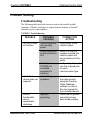
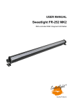
1
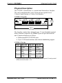
Crestron C3COM-3
3-Series™ Control Card
3 COM Ports
Installation Guide
This document was prepared and written by the Technical Documentation department at:
Regulatory Compliance
This product is Listed to applicable UL Standards and requirements by Underwriters Laboratories Inc.
As of the date of manufacture, the C3COM-3 has been tested and found to comply with specifications for CE
marking and standards per EMC and Radiocommunications Compliance Labelling.
Federal Communications Commission (FCC) Compliance Statement
CAUTION: Changes or modifications not expressly approved by the manufacturer responsible for
compliance could void the user’s authority to operate the equipment.
NOTE: This equipment has been tested and found to comply with the limits for a Class B digital device,
pursuant to part 15 of the FCC Rules. These limits are designed to provide reasonable protection against
harmful interference in a residential installation. This equipment generates, uses and can radiate radio
frequency energy and, if not installed and used in accordance with the instructions, may cause harmful
interference to radio communications. However, there is no guarantee that interference will not occur in a
particular installation. If this equipment does cause harmful interference to radio or television reception,
which can be determined by turning the equipment off and on, the user is encouraged to try to correct the
interference by one or more of the following measures:
•
Reorient or relocate the receiving antenna
•
Increase the separation between the equipment and receiver
•
Connect the equipment into an outlet on a circuit different from that to which the receiver is connected
•
Consult the dealer or an experienced radio/TV technician for help
Industry Canada (IC) Compliance Statement
CAN ICES-3(B)/NMB-3(B)
The specific patents that cover Crestron products are listed at patents.crestron.com.
Crestron, the Crestron logo, 3-Series, and 3-Series Control System are either trademarks or registered
trademarks of Crestron Electronics, Inc. in the United States and/or other countries. UL and the UL logo are
either trademarks or registered trademarks of Underwriters Laboratories, Inc. in the United States and/or other
countries. Other trademarks, registered trademarks, and trade names may be used in this document to refer to
either the entities claiming the marks and names or their products. Crestron disclaims any proprietary interest
in the marks and names of others. Crestron is not responsible for errors in typography or photography.
©2013 Crestron Electronics, Inc.
Crestron C3COM-3
3-Series Control Card
Contents
3-Series Control Card – 3 COM Ports: C3COM-3
1
Introduction ............................................................................................................................... 1
Specifications .............................................................................................................. 2
Physical Description .................................................................................................... 3
Installation ................................................................................................................................. 4
Problem Solving ........................................................................................................................ 5
Troubleshooting........................................................................................................... 5
Further Inquiries .......................................................................................................... 6
Future Updates ............................................................................................................ 6
Return and Warranty Policies .................................................................................................... 7
Merchandise Returns / Repair Service ........................................................................ 7
Crestron Limited Warranty.......................................................................................... 7
Installation Guide – DOC. 7302C
Contents • i
Crestron C3COM-3
3-Series Control Card
3-Series Control Card –
3 COM Ports: C3COM-3
Introduction
The C3COM-3 is a 3-Series™ control card that provides three COM
ports. Each COM port supports bidirectional RS-232, RS-422, or
RS-485, and all COM ports comply with IEC 61000-4-5 Installation
Class 4 surge immunity levels. The card is designed to install in a control
card expansion slot of a 3-Series Control System® model PRO3 or AV31,
or 3-Series Card Interface model CEN-CI3-1 or CEN-C13-32.
1. AV3 requires CAGE3 Control Card Expansion Cage accessory to enable use of
3-Series control cards.
2. The C3COM-3 is not compatible with the 2-Series PRO2/AV2/PAC2. Even
installed in the CAGE3 Control Card Expansion Cage, the card is not compatible
with any 2-Series control system.
Installation Guide – DOC. 7302C
3-Series Control Card: C3COM-3 • 1
Crestron C3COM-3
3-Series Control Card
Specifications
Specifications for the C3COM-3 are listed in the following table.
C3COM-3 Specifications
SPECIFICATION
Communications
RS-232/422/485
DETAILS
For 2-way device control and
monitoring
Environmental
Temperature
41° to 113° F (5° to 45° C)
Humidity
10% to 90% RH
(non-condensing)
Heat Dissipation
4 Btu/h
Dimensions
Height
Width
Weight
Available Accessory
CNSP-XX
2 • 3-Series Control Card: C3COM-3
0.98 in (25 mm)
5.00 in (127 mm)
4 oz (114 g)
Custom Serial Interface Cable
Installation Guide – DOC. 7302C
Crestron C3COM-3
3-Series Control Card
Physical Description
The C3COM-3, shown below, is a circuit board fastened to a faceplate.
The card is manufactured to easily fit into an unoccupied slot in a
3-Series Control System or 3-Series Card Interface.
G
TX
RX
RTS
CTS
RS232
G
TX
RX
RTS
CTS
SEE MANUAL FOR
RS422/485 PINOUT
G
TX
RX
RTS
CTS
C3COM-3 Faceplate
COM 1
COM 2
COM 3
0.98 in
(25 mm)
C3COM-3
5.00 in
(127 mm)
The faceplate contains three identical 5-pin, 3.5 mm detachable terminal
blocks. Interface connectors for COM 1-3 ports are provided with the
unit. Connector details are as follows:
• Bidirectional RS-232/422/485 ports
• Up to 115.2k baud; hardware and software handshaking support
C3COM-3 Pin Out
*
PIN #
RS-232
RS-422
RS-485
1
2
GND
TX
GND
TX-
GND*
TX-/RX-
3
RX
RX+
Not used
4
RTS
TX+
TX+/RX+
5
CTS
RX-
Not used
A ground terminal connection is recommended but not required. Ground potential
difference must be under +/-4V.
Installation Guide – DOC. 7302C
3-Series Control Card: C3COM-3 • 3
3-Series Control Card
Crestron C3COM-3
Installation
Items required to install the C3COM-3 are already attached to the unit.
The only tools required are a Phillips screwdriver and a grounding strap.
Follow the procedure below.
CAUTION: The C3COM-3 contains electrostatic sensitive devices
(ESD); observe precautions for handling ESDs to avoid damaging the
card.
NOTE: If installing the C3COM-3 into an AV3, it is assumed that the
CAGE3 Control Card Expansion Cage accessory has been installed.*
1. Disconnect power from the control system.
2. Use the Phillips screwdriver and remove two screws and blank
faceplate from the control system.
3. Align the C3COM-3 with the card guides in the open slot and slide
the expansion card into position.
4. Firmly press on both ends of the C3COM-3 faceplate to seat the
expansion card into the control system connector.
5. Tighten the thumb screws to secure the C3COM-3 to the control
system.
6. Reapply power to the control system.
*
C3COM-3 is not compatible with the 2-Series PRO2/AV2/PAC2. Even installed
in the CAGE3 Control Card Expansion Cage, the card is not compatible with any
2-Series control system.
4 • 3-Series Control Card: C3COM-3
Installation Guide – DOC. 7302C
Crestron C3COM-3
3-Series Control Card
Problem Solving
Troubleshooting
The following table provides corrective action for possible trouble
situations. If further assistance is required, please contact a Crestron®
customer service representative.
C3COM-3 Troubleshooting
TROUBLE
POSSIBLE
CAUSE(S)
C3COM-3 does
not function.
Control system is
not receiving
power.
Circuit card is not
properly seated in
slot.
Controlled
device does not
respond.
Loss of
functionality
due to
electrostatic
discharge.
Installation Guide – DOC. 7302C
Cable from
C3COM-3 to
controlled
equipment is
incorrect.
Cable/Wiring
problems.
Improper
grounding.
CORRECTIVE
ACTION
Verify power to the
control system.
Verify C3COM-3 is
properly inserted into
control system slot
per procedures in this
guide.
Verify wiring. Connect
only the required pins
for each
communication type.
Confirm and/or check
the cable pinouts
using the Crestron
Cable Database
software or refer to
the user manual for
the controlled device.
Check that all ground
connections have
been made properly.
3-Series Control Card: C3COM-3 • 5
3-Series Control Card
Crestron C3COM-3
Further Inquiries
To locate specific information or to resolve questions after reviewing this
guide, contact Crestron's True Blue Support at 1-888-CRESTRON
[1-888-273-7876] or refer to the listing of Crestron worldwide offices on
the Crestron Web site (www.crestron.com/offices) for assistance within a
particular geographic region.
To post a question about Crestron products, log onto the Online Help
section of the Crestron Web site (www.crestron.com/onlinehelp). Firsttime users must establish a user account to fully benefit from all available
features.
Future Updates
As Crestron improves functions, adds new features and extends the
capabilities of the C3COM-3, additional information may be made
available as manual updates. These updates are solely electronic and
serve as intermediary supplements prior to the release of a complete
technical documentation revision.
Check the Crestron Web site periodically for manual update availability
and its relevance. Updates are identified as an “Addendum” in the
Download column.
6 • 3-Series Control Card: C3COM-3
Installation Guide – DOC. 7302C
Crestron C3COM-3
3-Series Control Card
Return and Warranty Policies
Merchandise Returns / Repair Service
1.
No merchandise may be returned for credit, exchange or service without prior authorization from
Crestron. To obtain warranty service for Crestron products, contact an authorized Crestron dealer.
Only authorized Crestron dealers may contact the factory and request an RMA (Return
Merchandise Authorization) number. Enclose a note specifying the nature of the problem, name
and phone number of contact person, RMA number and return address.
2.
Products may be returned for credit, exchange or service with a Crestron Return Merchandise
Authorization (RMA) number. Authorized returns must be shipped freight prepaid to Crestron, 6
Volvo Drive, Rockleigh, N.J. or its authorized subsidiaries, with RMA number clearly marked on
the outside of all cartons. Shipments arriving freight collect or without an RMA number shall be
subject to refusal. Crestron reserves the right in its sole and absolute discretion to charge a 15%
restocking fee plus shipping costs on any products returned with an RMA.
3.
Return freight charges following repair of items under warranty shall be paid by Crestron,
shipping by standard ground carrier. In the event repairs are found to be non-warranty, return
freight costs shall be paid by the purchaser.
Crestron Limited Warranty
Crestron Electronics, Inc. warrants its products to be free from manufacturing defects in materials and
workmanship under normal use for a period of three (3) years from the date of purchase from Crestron,
with the following exceptions: disk drives and any other moving or rotating mechanical parts, pan/tilt heads
and power supplies are covered for a period of one (1) year; touch screen display and overlay components
are covered for 90 days; batteries and incandescent lamps are not covered.
This warranty extends to products purchased directly from Crestron or an authorized Crestron dealer.
Purchasers should inquire of the dealer regarding the nature and extent of the dealer's warranty, if any.
Crestron shall not be liable to honor the terms of this warranty if the product has been used in any
application other than that for which it was intended or if it has been subjected to misuse, accidental
damage, modification or improper installation procedures. Furthermore, this warranty does not cover any
product that has had the serial number altered, defaced or removed.
This warranty shall be the sole and exclusive remedy to the original purchaser. In no event shall Crestron
be liable for incidental or consequential damages of any kind (property or economic damages inclusive)
arising from the sale or use of this equipment. Crestron is not liable for any claim made by a third party or
made by the purchaser for a third party.
Crestron shall, at its option, repair or replace any product found defective, without charge for parts or labor.
Repaired or replaced equipment and parts supplied under this warranty shall be covered only by the
unexpired portion of the warranty.
Except as expressly set forth in this warranty, Crestron makes no other warranties, expressed or implied,
nor authorizes any other party to offer any warranty, including any implied warranties of merchantability or
fitness for a particular purpose. Any implied warranties that may be imposed by law are limited to the terms
of this limited warranty. This warranty statement supersedes all previous warranties.
Installation Guide – DOC. 7302C
3-Series Control Card: C3COM-3 • 7
Crestron Electronics, Inc.
15 Volvo Drive Rockleigh, NJ 07647
Tel: 888.CRESTRON
Fax: 201.767.7576
www.crestron.com
Installation Guide – DOC. 7302C
(2032617)
01.13
Specifications subject to
change without notice.