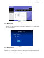
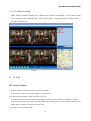
1
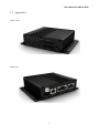
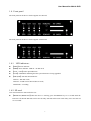
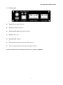
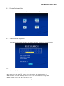
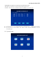
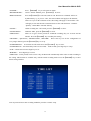
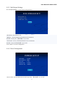
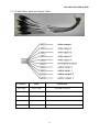
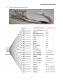
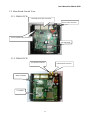
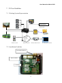
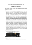
User Manual for Mobile DVR 4CH MINI Mobile DVR USER MANUAL 6000 series SD card record model Ver. 3.0 1 User Manual for Mobile DVR Contents 1. System Introduction....................................................................................................................................... 4 1.1. Features.............................................................................................................................................. 4 1.2. Appearance ........................................................................................................................................ 5 1.3. Remote Control ................................................................................................................................. 6 1.4. Front panel ......................................................................................................................................... 7 1.5. 1.4.1. LED indicators:...................................................................................................................... 7 1.4.2. SD card: ................................................................................................................................. 7 Back panel ......................................................................................................................................... 8 2. Specifications ................................................................................................................................................ 9 3. Technique Parameters .................................................................................................................................. 10 4. GUI .............................................................................................................................................................. 11 5. 4.1. Login................................................................................................................................................ 11 4.2. System Main Interface ..................................................................................................................... 12 4.3. Video Records Playback .................................................................................................................. 12 4.4. System Settings ............................................................................................................................... 13 4.4.1. Basic Settings ...................................................................................................................... 14 4.4.2. Recording Settings ............................................................................................................... 14 4.4.3. Sub-Stream Settings............................................................................................................. 16 4.4.4. Power Management ............................................................................................................. 16 4.4.5. Alarm Settings ..................................................................................................................... 17 4.4.6. Security Settings .................................................................................................................. 18 4.4.7. Network Settings: ................................................................................................................ 19 4.5. System Info...................................................................................................................................... 21 4.6. Management Tools........................................................................................................................... 22 4.6.1. Log Management ................................................................................................................. 22 4.6.2. SD Card Management.......................................................................................................... 23 4.6.3. Default Settings ................................................................................................................... 24 4.6.4. Config Management ............................................................................................................ 24 Device Installation ....................................................................................................................................... 25 5.1 Cable Definition ...................................................................................................................... 25 5.1.1 Power Cable................................................................................................................................ 25 5.1.2 Audio/Video Input and Output Cable ......................................................................................... 26 5.1.3 Alarm Input and Output Cable .................................................................................................... 27 5.2. Main Board Outside View .................................................................................................................... 28 5.2.1. FB6001 PCB .............................................................................................................................. 28 5.2.2. FB6002 PCB .............................................................................................................................. 28 6. System Upgrade User Guideline ................................................................................................................. 29 2 User Manual for Mobile DVR 6.1. MU-MINI-RFS.crc(Record File System)Upgrade ..................................................................... 29 6.2. MU-MINI-APP.crc(Application Program)Upgrade ................................................................... 29 6.3. MCU Upgrade ................................................................................................................................. 29 6.4. Upgrade Check out ....................................................................................................................................... 29 7. 3G User Guideline ....................................................................................................................................... 30 7.1. Working System Representation ...................................................................................................... 30 7.2. Installation Guideline ...................................................................................................................... 30 7.3. Parameter Settings ........................................................................................................................... 31 7.4. 8. 7.3.1. Network Setting ................................................................................................................. 31 7.3.2. Wireless setting .................................................................................................................. 32 7.3.3. Statues check out ................................................................................................................ 32 PC software setting .......................................................................................................................... 33 F.A.Q ........................................................................................................................................................... 33 8.1. Wireless Module ............................................................................................................................ 33 8.2. General Problems ............................................................................................................................ 34 3 User Manual for Mobile DVR 1. System Introduction 1.1. Features H.264 main profile Video compression format; Support 1 to 4 channels video input. Adopt 10bit video decoder processor to ensure picture quality, and each video channel is attached with an independent video decoder to avoid disturbing from each other. Industrial grade design: all electronic components conform to industrial standard through the entire design, including the special connectors dedicated for mobile DVR. Built-in GPS, G sensor (optional). Built-in wireless module like 3G (EVDO, HSPA, HSDPA), GPRS, WiFi (optional). With the special UPS technology, the DVR will work for another 10 to 15 sec after power failure, which makes the device shut down normally and keep the file safe Real time recording: 100f/s (PAL); 120f/s (NTSC). Recording resolution: CIF/ 2CIF/ D1 optional, maximum support 2CH of D1 + 2CH of CIF. Support 1 channel audio input, 1 channel microphone or audio line in. G.726 compression. 4 channels alarm input/ 2channels alarm output. RS232 interface for remote control; RJ45 10M/100M Ethernet port. Video recording mode: Auto, alarm, timed and manual recording. The video file format is ASF. The file can be played by general media player VLC or our customized software which support 1 channel or 4 channels synchronous playback Storage capacity: two 32GB SD card (the default selection is one SD card support). Quick start-mode: the device will turn to working in 20 sec after power on. Other start- or close- mode including ACC on, timed turn on/off, manual boot/shutdown the device. Voltage supply range is from 8V to 36V, the DVR is compatible with the most of vehicles. Power output is 12V/1.5A. Energy- efficient design, the power consumption is less than 5W with normal operating state. With anti-vibration and anti-high temperature protection, the quality of video files is always guaranteed Operating temperature: -25℃ to +70℃ All materials and PCB production conform to RoHs standard. Elegant and industrial design: Mini size, for easy installation, more concealing. Dimensions: 112(W) x36(H) x138(D) mm FB 6001 Weight: 0.36KG, FB 6002 Weight: 0.45KG; 4 User Manual for Mobile DVR 1.2. Appearance Front view: Back view: 5 User Manual for Mobile DVR 1.3. Remote Control KEY Function To activate the device 【LOGIN】 To enter system settings. 【0-9】 【0-9】: Under the configuration mode, 0~9 stand for numbers; under the playback mode, 1, 2, 3 and 4 are for switching between related single channel, and the number 5 is for 4 channels synchronous playback 【-】 【+】 For setting date and time 【DEL】 Backspace 【EXIT】 Return to the previous interface 【ENTER】 Enter button ▲, up, down, left, right , , left and right buttons are use for decreasing or increasing volume 【GOTO】 Select time period for playing video 【INFO】 To display system info under monitoring mode With the backward playing button, the video files can be played with 2/4/8/16 times speed. Press „play‟ button to get a normal speed play. Play button With the forward playing button, the video files can be played with 2/4/8/16 times speed forwardly. Press „play‟ button to get a normal speed play. Reserved Stop button is to stop the normal playing and return back to the playlist interface Pause button. Pause the normal playing. 【F1】 For FB6002 only. Under monitoring mode, it is used to display the info of G-sensor, GPS, wireless module, SIM card, dial-up and so on. 【F2-F3】 Reserved 6 Picture User Manual for Mobile DVR 1.4. Front panel The front panel for the device which supports two SD card: The front panel for the device which supports one SD card: 1.4.1. LED indicators: 【PWR】Power indicator. 【ERR】Error indicator: LED on-No SD cards 【CH1-CH4】Video input indicators 【CH1】LED blinks indicating that the system firmware is being upgraded. 【SD1,SD2】SD card status Indicator: LED on-SD card works; LED off-no SD card or SD card doesn‟t work; LED blinks-recording. 1.4.2. SD card: User must format new SD Card before use. 【REMOVE1,REMOVE2】when the device is working, press the RMOVE key for 3 seconds until the LED was off, then the SD cards can be moved safely. SD cards will resume work if they were not removed in 15 seconds.. 7 User Manual for Mobile DVR 1.5. Back panel 【PWR】Power Supply connector 【GPS】GPS antenna connector 【WIRELESS】WIRELESS antenna connector 【USB】USB1.1 port 【ETHERNET】LAN port. 【ALARM IN/OUT】Alarm input and output connector 【VI/VO AI/AO】Audio and video input and output connector Remark: GPS and wireless transmission functions are available with FB6002. 8 User Manual for Mobile DVR 2. Specifications Function Item Description Channel 1-4 channels Resolution 1-4 levels, 1 is the highest level and 4 is the lowest level. OSD Overlays information such as date time and vehicle ID SD card REC Recording Mode Preview Disk Data overwritten Video Search Playback System GUI 1 to 25f/s/ch adjustable (PAL) or 30f/s/ch (NTSC) . Video Quality Recording System Support CIF、HD1、D1 resolution, compatible with 2CH of D1 & 2CH of CIF. fps: Support two SD card recycle recording. Automatically switch to the other one when the first SD card was full, and the data will be automatically overwritten . The default setting is auto recording after power on. Timed recording and alarm recording are supported. Support 1 channel and 4 channels preview. Support SD cards overwritten function. Search video files anytime per day, type(n/a) and target SD card. Support 1 to 4 channels playback. Playback Graphical User Interface Support forward and backword play at the speed of: x 2,x4,x8,x16. Setup system parameters with the remote control. Support up to 4 channels alarm input. Alarm Input Record duration after alarm can be set in system Output GPS Optional Function Pre-record 15 seconds ahead of the alarm. Network Support up to 2 channels alarm output, level signal. GPS module can be built-in device FB6002, the GPS info will be recorded synchronous RJ45 Ethernet port. FB6002 supports several wireless modules such as 3G and WIFI G Sensor Built in G-sensor is available with FB 6002 System auto power on/off: Power Settings Others 1,Vehicle acc on/off---system auto power on after acc on, system power off according to the delay time (up to 240min, default 5min) after acc off. 2,Preset time---Only according to time preset table. Power-off With the power-off protection, all data can be saved safely and the recording can protection be closed normally after power failure. 9 User Manual for Mobile DVR 3. Technique Parameters System Item Description Processor Hisilicon Hi3511 Operating system Linux(2.6) Signal format PAL/NTSC GUI Yes Security Video Two level password protections for administrators and users Input 4 CVBS, 1.0Vp-p, 75Ω Output 1 CVBS, 1.0Vp-p, 75Ω Play channels 1 channel or 4 channels synchronous play PAL: 25Frame/s ,CCIR625 line,50 field Recording speed Audio NTSC: 30Frame/s,CCIR525 line,60 field Input Mic or line in, 1 channel Output 1 channel output Output voltage 1V ~2V Audio recording Synchronized with video Audio compression G.726 Video compression H.264,(VBR)/ (CBR) Recording Resolution D1/HD1/CIF, MAX:2 channels of D1 and 2 channels of CIF Video stream standard ISO14496-10 Audio stream standard G.726 video recording CIF: 256Kbps ~ 1.5Mbps, 4 quality level support, Bit rate HD1: 600Kbps ~ 2.5Mbps, 4 quality level support D1: 800Kbps ~ 3Mbps, 4 quality level support Video Frame rate PAL 1~25/s/ch,NTSC 1~30/s/ch Audio frame rate 5KB/s 10 User Manual for Mobile DVR Support two (SDHC) SD card, the max capacity is 32G for Storage capacity each. File system: FAT32 input 4Ch input output 2Ch output Communication RS-232 Yes Interface RJ45 10M/100M Ethernet GPS Embedded GPS module Optional PC Viewer PC playback software Yes Firmware upgrade Upgrade with SD card Yes Power input DC:+8V ~ +36V Power output +12V@1.5A;+5V@1.5A Operating temperature -25℃ to +70℃ Humidity 20% to 80% Alarm Others 4. GUI 4.1. Login Factory Default Username: admin Factory Default Admin Password: 888888 Factory Default User Password: 111111 11 User Manual for Mobile DVR 4.2. System Main Interface The main interface will be displayed on the screen when you login successfully, it contains 4.3. Video Records Playback Select „Playback‟ icon with left/right/up or down key and press „enter‟ key to get below interface Note: System will highlight the valid recording info in yellow color "REC TYPE": press the【Enter】 button to select All or Alarm. The default setting is All. “DISK SELECT ": press the【Enter】 button to select the SD card: The default setting is SD1. "DATE": Default is current day. Press digit keys to reset 12 User Manual for Mobile DVR "START TIME": Press digit keys to setup the start time, default setting is 00:00. "END TIME": Press digit keys to setup the end time, default setting is 23:59. "SEARCH": Take curser move to "SEARCH" and press the【Enter】 key to see the result. Press direction keys to view recording information, press 【Enter】 to play , Press direction keys to select "FIRST", "UP", "NEXT", "LAST", and press 【ENTER】 to enter the corresponding page. 4.4. System Settings 13 press【ESC】 to return back; User Manual for Mobile DVR 4.4.1. Basic Settings “DATE TYPE”: year/month/day, day/month/year or month/day/year. Press 【ENTER】 to select. "DATE": system date, press 【ENTER】and then press【-】or【+】 to setup, press【ENTER】again to confirm the settings. Press left/right to select year/month/day and repeat above steps. "TIME": The same setup as “DATE”. "OPR TIMEOUT": All system Interface closed time, default time is 30s. Press digit keys to setup the operating closing time. "DEV NUM": It refers to the device ID. Press digit keys to setup the ID. "COMPANY NAME", "VEHICLE NO", "DRIVER NAME",”LINE NUM”: Press 【Enter】 key to get the keyboard window displayed, and use left/right/up/down/enter key to setup. Select “SAVE” and press 【ENTER】to save the settings. 4.4.2. Recording Settings RECORD SETUP SYSTEM: OVERWRITTEN: PAL/NTSC ON/OFF RECORD MODE: ATUO/TIMED/ALARM/MANUAL ALARM DELAY: 30 S(30S~1800S) RESOLUTION:D1/HD1/CIF AUDIO : ON/OFF GOP: 30 BITRATE: 2048 AUDIO INPUT: LINE IN/MIC TIME LIST TIME SLICE: 15/30/45/60 (MIN) CHANNEL QUALITY FRAME RATE RECORD CH1( CH1(1~4) 1~4) 1(1~4) 1~4) 25/30 ON/OFF SAVE SUB-STREAM 14 User Manual for Mobile DVR "SYSTEM ": Press 【ENTER】 key to select PAL or NTSC "RECORD MODE": AUTO / Timed / Manual, press 【ENTER】 to select. "RESOLUTIONS": Press the【ENTER】to select D1, HD1 or CIF. Please note 4 channels will be set Synchronously, e.g. if you set “CIF”, the CIF resolution will apply to all channels; However if you set the resolution as D1, this setting will apply to ch1 and ch2+ CIF will apply to ch3 and ch4. The resolution doesn‟t relate with the below “Channel” “Quality” “Frame Rate””Record” directly. "AUDIO ": Audio recording On / Off switch, press the【ENTER】to select. "AUDIO INPUT": LINE IN / MIC, press the【ENTER】to select. "TIME SLICE": There are 4 types of time period for continued recording, they are 15/30/45 and 60 minutes. Press the【ENTER】key to modify this setting. "CHANNEL", "QUALITY", "FRAME RATE", "RECORD": Those four keys are for the configuration of every single channel, press the【ENTER】key to set up. "OVERWRITTEN": Overwritten on/off switch. Press the【ENTER】 key to select. "ALARM DELAY ": Set alarm delay between 30 seconds ~ 1800 seconds, press digit keys to setup "GOP": I-frame interval. Press digit keys to set “BITRATE”: Press digit keys to select. "TIME LIST": 2 time periods can be set for a day; the DVR will automatically make video records according to the setting. This function is available only with the timed recording mode. Press the【ENTER】key to enter below setting interface. Note: System will auto start recording within the period in “Timed” setup. 15 User Manual for Mobile DVR 4.4.3. Sub-Stream Settings Press the【ENTER】key to enter below setting interface. SUB-STREAM SET RESOLUTION: CIF BITS RATE: 16~200 FRAME RATE: 01~20 SAVE "Resolution": The default is CIF. "Bit Rate": 16/24/32/40/48/56/64/72/80/96/128/160/200 bits. Default is 96 bit, press 【ENTER】 key to enter "Frame Rate": 01/01/01/02/02/03/04/05/07/10/13/15/20 frame Default is 10f, press【ENTER】 key to enter. Click ‟SAVE‟ to save the configuration. 4.4.4. Power Management "Power mode": start up and shut down mode by pressing 【ENTER】 key to select. 16 User Manual for Mobile DVR TIME: DVR will auto power on/off according to the preset time table. ACC: System will auto power on/off according to vehicle acc switch on/off signal. "DELAY POWER OFF": When this function is on, the DVR will continue making record for a while as per the configuration. When this function is off, the DVR will shut down when ACC is off. Press „enter‟ key to select. “TIME”; Off---Shut down system at once. Press 【ENTER】key to select. "DELAY TIME": Press digit keys to select. The range is between 3 and 300mins. "POWER ON TIME": Press digit keys to select. "POWER OFF TIME": Press digit keys to select. 4.4.5. Alarm Settings Alarm input Support 4ch alarm input. "ENABLE": switch on/off. ON---Enable alarm input; OFF---Disable alarm input. Press the 【ENTER】 key to select on or off to enable or disable alarm input. "Level Setting ": Setup input alarm level signal. HIGH---high electrical level input signal will enable alarm. Press „enter‟ to set the level. High or low level can be set with input signal; open or close can be set with output signal. "RECORD": ON---Enable alarm recording; OFF---Disable alarm recording. Press the【ENTER】to select on or off to enable or disable recording. Alarm output Support 2ch alarm outputs. “ENABLE”: On/Off switch. ON---Enable alarm output; OFF---Disable alarm output. Press the 【ENTER】 key to select. 17 User Manual for Mobile DVR PWL: power level output for alarm. High stands for high power level output and low refers to low power level output. Select and press “SAVE” to save all setup. G SENSOR(This functions is available with FB6002) GSENSOR setup, Press the 【ENTER】 key to enter below setting interface for G-sensor configuration: “LIMIT”: Limit value for X/Y/Z, Minimum value is 0.00g and Maximum value is 9.99g, press digit keys to setup. “ALARM”: G-Sensor alarm OPEN/CLOSE setup, press 【ENTER】to set it. Alarm Open: Open alarm recording and alarm files will be recorded when X/Y/Z value over than “Limit value” under record stautes Alarm Close: Close alarm recording and alarm files will not be recorded when X/Y/Z value over than “Limit value” under record stautes “CHECK”: Adjust X/Y/Z current values when user start up device at first time, Press the【ENTER】key to confirm. After “CHECK”, X/Y/Z value will be “0” Remark: Please do remember to click “SAVE” to save data after setting. 4.4.6. Security Settings 18 User Manual for Mobile DVR Password setting: "PASSWORD": ON---Enable password; OFF---Disable password, press the【ENTER】 key to select. Select and press “SAVE” to save the configuration. 4.4.7. Network Settings: Network parameters should be set on the device. The system will detect devices without any further setting if the configuration is correct . NETWORK LOCAL NETWORK IP ADDRESS: 192. 168. 000. 100 NETMASK:255. 255. 255. 000 GATE WAY:192. 168. 000. 001 MAC: 00.44.53.75.55.56 CENTER SET TYPE:IP/DOMAIN DOMAIN:www.123.cn SERVER IP:192 . 168 . 001 . 170 CONTROL PORT:5678 MEDIA PORT: 5678 SAVE Wireless DDNS Local network: RJ45 for LAN Setup device IP address, mask and gate way. Attention: IP address conflict with other host computer. Center setup 19 User Manual for Mobile DVR Server IP: Set the IP address same as PC client. Type: IP/DOMAIN DOMAIN: Default is www.123.cn. Control port: Default is 5678. Media port: Default is 5678. 3G wireless transmission settings (this is available with FB6002) Press 【ENTER】 key to enter the following interface: WIRELESS WIRELESS: TYPE: APN: CENTER NUM: ON/OFF WCDMA/EVDO/TD CMNET *99***1# USER NAME: card PASSWORD: card SAVE “WIRLESS”: ON—enable wireless; OFF—Disable wireless, press the【ENTER】 key to select. “TYPE”: WCDMA—WCDMA module; EVDO—EVDO module, TD-TD module press the【ENTER】 key to select. “APN”: APN CMWAP, Press the【Enter】 key to enable the keyboard window, then use left/right/up/down/ enter key to setup. “CENTER NUM”: Center number, Press the【Enter】 key to pop out keyboard window, then use left/right/up/down/ enter key to setup. “USER NAME”: Press the【Enter】 key to pop up keyboard window, then use left/right/up/down/ enter key to setup. “PASSWORD”: Press the【Enter】 key to pop up keyboard window, then use left/right/up/down/ enter key to setup. Click “SAVE” to save all setup. ● DDNS "DDNS": Cursor to the " DDNS ", Press the【ENTER】key to enter below interface. 20 User Manual for Mobile DVR DDNS DDNS: CLOSE/OPEN USERNAME: WCDMA/EVDO PASSWORD: card SAVE DDNS: Close / Open, with 【Enter】 key to select. "User Name", "Password": user name and password for setting DDNS, press 【Enter】 key to enter, then go to the keyboard interface, move the cursor and input corresponding letter through press 【Enter】 key. Click the “SAVE” after complete setup 4.5. System Info "FIRMWARE VER": Software version number. "HARDWARE VER": Hardware version number. "MCU VER": Single-chip version number. "SD NUM": Name of SD card. "TOTAL ": the total capacity of SD card. 21 User Manual for Mobile DVR "Remaining ": The remaining space of SD cards 4.6. Management Tools Management tools include log manager, disk manager and system default settings. MANAGE TOOL LOG MANAGE DISK MANAGE DEFAULT SET CFG MANAGE 4.6.1. Log Management Log manager will record the alarm info including date, time and name “START TIME”: press digit keys to set up the start time for an inquiry of a log "END TIME": Until what time to search the logo, press digit keys to setup. 22 User Manual for Mobile DVR "SEARCH": press the enter key to search all log info in this time period. Press the direction keys to select "FIRST", "UP", "NEXT", "LAST ", and press the【ENTER】 key go to corresponding page. 4.6.2. SD Card Management Disk management is used to format the SD cards. "SD SELECT": to select SD1 or SD2 by pressing the „enter‟ key. "CANCEL": Cancel disk management operations, and return back to the management tool interface. "FORMAT": Select the format button, and press the enter key to enable below window for formatting SD cards: "Yes": press the【ENTER】key to start formatting. 23 User Manual for Mobile DVR "No": Cancel formatting and return back to the disk management interface. 4.6.3. Default Settings "Yes": Press the【ENTER】key to recover all parameters to the original default settings. "No": Cancel this operation and return back to the management tool interface. 4.6.4. Config Management Import and export config file CONFIG MANAGE IMPORT CONFIG FILE: IMPORT FILE DVR.CFG IN SD ROOT IMPORT CFG EXPORT CURRENT CONFIG FILE: SAVE AS DVR.CFG IN SD ROOT EXPORT CFG Import Configuration: Import the “DVR.CFG” file into device from the SD card Export Configuration: Export the “DVR.CFG” file from device to the SD card 24 User Manual for Mobile DVR 5. Device Installation 5.1 Cable Definition 5.1.1 Power Cable Black color cable: connect with cathode on battery in vehicle Red color cable: connect with anode on battery in vehicle Yellow color cable: connect with ignition in vehicle. Notes: 1: Please make sure the battery voltage range within 12-24V, otherwise device will break down when voltage more than 24V 2: Please check out the three cables and make sure isolative between them after complete connection 3: Make sure connect the Black and Red cables with battery directly and never choose ground strap connection way as GND, otherwise device cannot work normally 4: The yellow cable must be connected to the ignition; otherwise device will not support ignition switch machines. 25 User Manual for Mobile DVR 5.1.2 Audio/Video Input and Output Cable Connector Name Instruction Video Input VIN1~VIN4 4 VIN BNC connector Video Output VOUT 1 VOUT BNC connector Audio Input AIN1~AIN2 2 AIN BNC connector Audio Output AOUT1~AOUT2 2 AOUT PCA connector MIC Input MIC IN 1 MIC IN RCA connector 26 User Manual for Mobile DVR 5.1.3 Alarm Input and Output Cable 27 User Manual for Mobile DVR 5.2. Main Board Outside View 5.2.1. FB6001 PCB Alarm IN/OUT cable connector Power cable connector VI/VO AI/AO cable connector SD card holder 5.2.2. FB6002 PCB 3G antenna connector SIM card holder 3G module 28 GPS antenna connector User Manual for Mobile DVR 6. System Upgrade User Guideline 6.1. MU-MINI-RFS.crc(Record File System)Upgrade 1. Cope files into SD card. Make sure files were copied totally 2. Insert SD card into device before power on 3. Power on the device and all indicator except SD1 and SD2 will be light. 4. “LOADING” and “ERASING FLASH”showed on window, mainwhile PWR light one and CH1 indicator on front pannel flicking, it means upgrading. 5. Progress bar will be showed on the window (1%--100%). When the bar is full, it means upgrade complete. Remark: After upgrade, the file in SD card will be deleted automatically. 6.2. MU-MINI-APP.crc(Application Program)Upgrade 1. Process same as above. Remark: After upgrade, a new debugger information file will appear automatically in SD card. 6.3. MCU Upgrade 1. Process same as above.When MCU upgrade, SD1 indicator will be light.. 2.“UPGREAD MCU”and “REBOOT!”will show in turn.. 3. Device will restart automatically when upgrade complete. 6.4. Upgrade Check out Go back to monitor window after upgrade, and then press “INFO‟ on remote control or go to „System info” interface to check out upgraded version. Note: 1) Make sure stop any operation during upgrading. 2) Make sure the file which need to be upgraded has been saved into SD card and device must be in “power off” statues before upgrade. 3) Upgrade step by step. The correct sequence is Record File SystemApplication ProgramMCU. 4) Device will restart automatically when upgrade complete. 29 User Manual for Mobile DVR 7. 3G User Guideline 7.1. Working System Representation External Module G Sensor,GPS WCDMA 3G/EVDO HSPA Remote Control Wireless network Remote monitor center 7.2. Installation Guideline 3G antenna connector SIM card holder 3G Module 30 PC Management software User Manual for Mobile DVR 7.3. Parameter Settings 7.3.1. Network Setting NETWORK LOCAL NETWORK IP ADDRESS: 192. 168. 000. 100 NETMASK:255. 255. 255. 000 GATE WAY:192. 168. 000. 001 MAC: 00.44.53.75.55.56 CENTER SET TYPE:IP/DOMAIN DOMAIN:www.123.cn SERVER IP:192 . 168 . 001 . 170 CONTROL PORT:5678 MEDIA PORT: 5678 SAVE Wireless DDNS Picture 1 1) Server IP must be globe IP 2) Default Port is 5678. 3) If the computer which running Fclient in local area network, Port map must be setting in router (Please have a reference in picture 2) 4) There are two types IP setting: Domain and IP. 5) If customer set it as Domain, the user router must support DDNS. (Please have a reference in picture 3) Picture 2 31 User Manual for Mobile DVR Picture 3 7.3.2. Wireless setting There are 3 types: WCDMA, EVDO and TD. When user set it, please make sure the type you select must be match with the type of 3G modules (Please have a reference in picture 3) WIRELESS WIRELESS: TYPE: APN: CENTER NUM: ON/OFF WCDMA/EVDO/TD CMNET *99***1# USER NAME: card PASSWORD: card SAVE Picture 4 7.3.3. Statues check out 7) Press F1 key on remote control under preview interface to check out current statues. It will show the information about 3G modules. Such as whether 3G or SIM card exists or not. Signal and dial-up statues (Please have a reference in picture 4) 32 User Manual for Mobile DVR 7.4. PC software setting Make Fclient software running first. When device dial-up successfully, it will connect with sever setted by user automatically. Green color means connecting success (Please have a reference in picture 5) Remote ID Picture 5 8. F.A.Q 8.1. Wireless Module 1) Q: How to setup network after choose the wireless module? A: Please have a reference on eighteenth page in User Manual. 2) Q: When wireless module cannot work, how to solve it? A: Go back to preview interface, and press F1 button on remote control to check out whether network has been dialed up. You can also check out whether SIM card in working statues, wireless module existent or not, and the other possibility is antenna not connect well. 3) Q: Why 3G can not transmit data? 33 User Manual for Mobile DVR A: Probably of the reason is as follows: 1) Didn‟t connect 3G antenna 2) Didn‟t insert SIM card; 3) Wireless and network setup in a wrong way 4) The PC setup not matches with 3G. For example, the gateway router have not port mapping. 5) Have never turn on PC play back tool. Remark: For further more information about Network and Wireless setup, please have a reference on page eighteenth and nineteenth in User Manual. 4) Q: What kind of overwritten way use in device when two SD cards circularly recorded A: Record one by one. When the first one has no capacity, the second one will start to record. If two pieces of SD card are full, the device will delete the record data start from the one which record on the earliest time. 5) Q: Whether can achieve the 3 G long range previews and local record carry on synchronously or not? A: Real-time preview in control centre and save local record can be achieved. 6) Q: How about the 3G transmit speed? A: It will depend on the bandwidth of each Country. Currently in China, 4 channels video can be transmitted at the same time, the best situation is 15f/s/ch. 7) Q: How long time delay when 3G long range previews? A: It will depend on the bandwidth of each Country, the transmission delay within 5-20s in China. 8) Q: How to download record file through 3G? A: User can download files manually. 9) Q: Whether can set record in system in a long range through 3G or not? A: Sorry, it isn‟t realization currently. 10) Q: Is it the long range switch device operation? A: Temporary nonsupport, but engineer can add this function into system according to customer‟s acquirement. 11) Q: Is it all right to support SDHC card? A: Support SDHC card. 8.2. General Problems Problem 1: The power indicator not bright after power on. The following reasons will cause the power indicator not works: 1) Electric voltage isn‟t within the range of 8-36 V; 2) The fuse in power cable was burned; 3) ACC setting failure or ignition connects in a wrong way 34 User Manual for Mobile DVR Problem 2: ERR indicator keep on light. The following errors will cause the ERR indicator keep on light. 1) Two SD cards didn't be inserted. 2) The system partition under abnormal statues, even the SD card be inserted, it also can cause the equipments can not be identified; 3) MCU not works; 4) SD card cannot read and write in normal; Problem 3: Channel indicator not works The following reasons will cause the Channel indicator not works: 1) No video signal input; 2) Cameras break down; 3) Indicator is damaged; 4) The system cannot be operated in normal. Problem 4: SD card indicator not works or keep flicker The SD card indicator has 3 medium statuses: OFF, ON and Flicker; respectively meaning as follows: OFF: This SD card didn't be inserted or can not be identified by the equipments; ON: This SD card existence, but it isn't the one that is recording image at present; Flicker: This SD card exists and it is the one that is recording image at present; Possible reason is as follows: 1) User doesn‟t setup record in system; 2) Two SD cards all have already recorded full, but overwritten function was “off” in system 3) Although Overwritten function was “on” in system, all the files in two SD card are alarm record ones. These files cannot be deleted automatically so SD card can not memory new record files Remark: For further more information about indicator, please have a reference on page sixth in User Manual. Problem 5: Video Lost in certain channel Possible reasons are as follows: 1) This channel has no video input. 2) The camera of this channel breaks down or work abnormality; 3) If the camera takes an electricity power from the equipments directly, may be the equipment‟s electric voltage isn't enough to make camera work as usual; 4) The cable that links this channel has problem 35 User Manual for Mobile DVR Problem 6: Record files have no audio Probably of the reason is as follows: 1) Audio function setup in “OFF” mode in system 2) Use wrong input cables Audio input including two types. One is LINE IN and the other one is MIC IN. It will be showed on Record setup interface in system. User must select one of them before make a record. The cable AIN1 and AIN2 match with LINE IN mode, however cable MICIN match with MIC IN mode. 3) Audio output cable didn't connect or connect in a wrong way; Remark: Please have a reference about Audio setup on page thirteenth in user manual. Problem 7: Device cannot make a record successfully. The following reasons might cause this problem: 1) Recode mode setup in a wrong way There are 3 kinds of record mode: Auto, Timed and Alarm. Before recording, user must to setup record mode in system. If it was set in “Alarm” mode but has no alarm right now,” device will not make a record. If it was set in “Timed” mode but the current time not within timed period, same as above, device will not make a record as well. 2) Overwritten function was “OFF‟ and the capacity of SD card less than 500M, in this situation device will stop recording. 3) The ERR light of front panel shine. Can pass to look into a system information, If SD card space shows in “0”please check whether SD card has been formatted before use and inserts or not. 4) Record mode be set to “OFF” in each channel. Please press “Enter” button on remote control to switch “OFF” to “ON” mode before record, otherwise device will not make any record. Remark: Please have a reference on page thirteenth in user manual. Problem 8: Alarm input invalid. May be the following reason to cause this problem: 1) Alarm setup in a wrong way in system. 2) Alarm input cable did not connect to the device or cable not works 3) Alarm trigger signal to get an electric shock failure Problem 9: Alarm output invalid. Possible reason is as follows: 1) Cable connection in a wrong way. 2) System setting in a wrong way Remarks: More information and user guidelines please find on page fifteenth in user manual Problem 10: GPS signal lost 36 User Manual for Mobile DVR GPS has no signal, probably of the reason is as follows: 1) Didn‟t connect GPS antenna; 2) The GPS antenna put indoors; 3) The GPS module damages; 4) The software of device FB6001 nonsupport this function; Problem 11: G-Sensor data abnormal. The reason as below: 1) The software of device FB6001 nonsupport this function; 2) The G-Sensor damage; 3) User did not check the X/Y/Z data in system Remarks: More information and user guidelines please find on page seventeenth in user manual Problem 12: Can‟t playback files on PC successfully. Possible reason is as follows: 1) Have never chosen a record file or document path; please choose the path that records file first before playback. Problem 13: Remote control not works: Probably of the reason is as follows: 1) The remote control didn't pack battery; 2) The remote control damages; 3) The equipment breaks down; Problem 14: During playback, the map doesn't show. Possible reason is as follows: 1) Net cable did not connect to PC 2) Net works, but the computer can not get to the Internet; 37