1
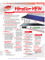
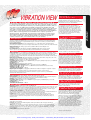
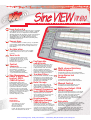
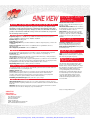
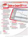
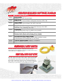
Artisan Technology Group is your source for quality
new and certified-used/pre-owned equipment
• FAST SHIPPING AND
DELIVERY
• TENS OF THOUSANDS OF
IN-STOCK ITEMS
• EQUIPMENT DEMOS
• HUNDREDS OF
MANUFACTURERS
SUPPORTED
• LEASING/MONTHLY
RENTALS
• ITAR CERTIFIED
SECURE ASSET SOLUTIONS
SERVICE CENTER REPAIRS
Experienced engineers and technicians on staff
at our full-service, in-house repair center
WE BUY USED EQUIPMENT
Sell your excess, underutilized, and idle used equipment
We also offer credit for buy-backs and trade-ins
www.artisantg.com/WeBuyEquipment
InstraView REMOTE INSPECTION
LOOKING FOR MORE INFORMATION?
Visit us on the web at www.artisantg.com for more
information on price quotations, drivers, technical
specifications, manuals, and documentation
SM
Remotely inspect equipment before purchasing with
our interactive website at www.instraview.com
Contact us: (888) 88-SOURCE | sales@artisantg.com | www.artisantg.com
S H A K E R
V I B R A T I O N
C O N T R O L
S Y S T E M
Familiar Microsoft
Windows Interface
The VibrationVIEW controller runs on all varieties of the Microsoft
Windows® operating system. Since most people are already familiar
with the Windows environment, this allows you, our customer, to
leverage your knowledge and accelerate your learning curve.
System Check
All VibrationVIEW software packages include a System Check mode
which provides a manually controllable sine wave output and
oscilloscope and spectrum analysis plots of the accelerometer inputs.
This test mode is used to calibrate the system and verify operation of
the controller, amplifier, shaker and accelerometers.
Networking (VR656 Option)
The system can easily be incorporated into your corporate network to
facilitate data sharing. The VibrationVIEW program may be installed on
any number of machines, using (optional) Net VibrationVIEW, and used
to view test data and create test reports from virtually anywhere.
Remote Control (VR655 Option)
A variety of remote monitoring and control options are
available. The controller can be monitored or controlled
via network and web with built-in web page and e-mail
server. Other applications can control the VibrationVIEW
program through any easy-to-use file-based interface.
External TTL logic level inputs and
outputs may also be used to start and
stop tests. Tests can be configured to
All of the VibrationVIEW
set and clear TTL logic level outputs
software packages share a
during the test to trigger external events.
common easy-to-use graphing
system. Graphs can be easily
auto-scaled or zoomed. Cursors
can be used to locate peaks
and highlight particular data
Industry standard active-x remote control.
points. Dataand text annotations
can be easily placed on the
graphs, with annotations updated
Calibrate the 8500 system hardware in
live as the data changes. Graph
your own calibration laboratory using
images and raw graph data can
your own calibration instruments with
be copied and pasted into your
the VR661 System Hardware Calibration
favorite word processor or
software. Or, perform automatic calibration
spreadsheet.
and verification of all your 8500 systems
with the combination of VR8500-AC
Calibration Equipment Package and
VR667 System Automated Calibration
Test reports can be easily
Verification software. Combination
created from customizable
provides all the necessary calibration
report templates. Graphs and raw
equipment, cables, and software.
numerical data can be transferred
through the Windows clipboard
into any word processor or
spreadsheet program.
Graphs
Active-X
(VR626 Option)
Calibration Standard
Documentation
Shaker Monitor &
Analog DC Inputs
(VR629 Option)
The 8 inputs on the back of the 8500 can
be set up as analog DC Monitor Inputs.
This allows the user to monitor, plot
graphs, and store data from up to 8 analog
signals. Including shaker current and
voltage. Software allows scaling to
your desired units. +/-10 volt range.
Also features high and low trip points,
which are user settable. A good way to
monitor the shaker’s armature voltage,
armature current, field voltage, and field.
VIBRATION
RESEARCH
CORPORATION
2385 Wilshere Dr. Suite A
Jenison, MI 49428 USA
PH (616) 669-3028
FAX (616) 669-5337
E-mail: sales@vibrationresearch.com
Web: www.vibrationresearch.com
Web server/
E-mail (VR627
Option)
Connect from anywhere in the
world to your 8500 test
controller with a web browser.
Alternate Units
(VR628 Option)
Allows you to monitor and
measure things like sound
pressure, micro strain, and
any other engineering units
by changing the inputs and
graphs to your engineering
units desired.
SOFTWARE
OPTIONS
SineVIEW
Run swept and/or fixed-frequency sine
wave vibration tests, with control over
acceleration, velocity and displacement.
RandomVIEW
Run controlled spectrum random
tests (tests with a spectrally shaped
gaussian amplitude distribution).
ShockVIEW
Run standard classical shock pulses
as well as (optional) user-defined or
SRS synthesized transient pulses.
Field Data
ReplicationVIEW
Reproduce, in your test lab on your
shaker, the actual acceleration waveforms you measured in the field. The
controller automatically compensates
for shaker and fixture responses.
Sine on
RandomVIEW
Run mixed-mode tests with sine
tones superimposed on a random
background.
Random on
RandomVIEW
Run controlled spectrum random
tests with swept random “tones”
superimposed on a random
background.
RecorderView
Record your field acceleration
measurements digitally, directly to
your PC’s hard drive. Matlab format.
8500 HARDWARE
SPECIFICATIONS
Input Channels
The system comes with
simultaneously sampled 24-bit
input A/D’s with 100dB dynamic
range. The input impedance is
100k ohms. 1 to 16 channels.
The channels are configured
in blocks of 4.
Output Channel
The system comes standard
with two 24-bit output
D/A’s with 100dB signal to
(noise+distortion) ratio.
Outputs are low impedance
with a range of 20-volt
peak-to-peak.
Ethernet
Interface
24-bit Accuracy
TEDS Interface
High Frequency
(VR657 Option)
Allows control past 4,000 Hz.
Sine, Random, and Shock control
to 20,000 Hz. FDR control
to 10,000 Hz.
Artisan Technology Group - Quality Instrumentation ... Guaranteed | (888) 88-SOURCE | www.artisantg.com
TECHNICAL
SPECIFICATIONS
Vibration Research’s hardware and software integration with your PC is easy. No need
to open the PC, and hunt for open PCI or ISA slots. Just connect the signal processing
front end to the PC through the ethernet port, load the application software, and you
are ready to test. The 8500 is rack mountable. Install it in the amplifier rack, and
connect to your PC with a simple Ethernet cable. Eliminates all the accelerometer and
drive cables going back to the control room! Great for getting rid of 50/60 Hz noise
problems, too, as the ethernet interface provides DC isolation between the 8500 and
the PC. Shaker control applications are available for the complete spectrum of
vibration testing - from random, sine and shock to mixed-mode, resonance dwell,
and "field data replication" of long duration waveforms, and waveform recording.
The control system comes with a Front End signal processing box, application
software, ethernet cable, a user manual, and a one-year warranty.
HARDWARE
Front End signal processing box: Low-noise design with a dedicated high speed processor for
signal processing. Front BNC connectors for 4 accelerometer connections. Front panel status LEDs.
Rear panel connectors drive output and COLA output, connection to ethernet port, and a terminal
block of digital I/O lines.
Input channel expansion: Can be expanded from 1 to 16 total analog inputs by adding signal
processing boxes. Each box processes 4 inputs. Additional boxes connect to the PC via a network switch.
Output channels: One analog output (drive) standard; COLA (Constant Output Level
Amplitude) optional.
PC configuration: PC with Windows 95/98/NT/2000/Me/XP Operating System, and an
ethernet
I N Pport
U Tare
Sthe only requirements. Microsoft Word and Excel are recommended.
INPUTS
Analog channels: 1 to 16 simultaneous channels. Each can be control, monitor, or disabled. All are
configurable single ended or differential with 200K Ohm impedance. Setup allows per channel selection
of transducer sensitivity, coupling (AC or DC), accelerometer constant current supply (4 mA), TEDS
transducer interface, and a unique DC offset that allows measurement to true DC with constant current
E L E C T R O D Y N A M I C
S H A K E R
type accelerometers.
Electronics per channel: Differential amplifier, configurable as differential, single ended, AC or DC,
anti-aliasing filters, and 24-bit Analog to Digital converter (ADC).
Filtering: An analog multiple pole filter plus a digital filter.
Frequency range: Capability of up to 20,000 Hz analysis frequency (Sample frequency up to 52,000 Hz).
Voltage range: +/- 10 Vpeak.
Resolution: 24-bit.
Dynamic range: 120 dB input signal separation.
Phase match between channels: Within +/- 0.5 degree from DC to 10,000 Hz.
Signal-to-noise ratio: >100 dB (from DC to 1,000 Hz measured with half-full-scale sine wave).
Channel cross-talk: <-110 dB.
Total harmonic distortion: <-105 dB.
Digital input and output: Rear pluggable terminal block enables the digital level signals - 8 inputs
and 8 outputs to be interfaced with your product and other systems. Used for remote
start/stop/pause/continue and other functions such as close/open control loop, manual/auto
schedule, and enable/disable aborts.
OUTPUTS
Analog channels: One drive channel standard. One COLA output optional.
Drive channel: 24-bit Digital to Analog Converter (DAC), anti-imaging filter, and optional emergency
stop shutdown circuit, and power failure transient prevention shutdown circuitry.
Filtering: Analog multiple pole filter plus a digital filter.
Frequency range: Capability of up to 20,000 Hz output frequency (52,000 samples per second).
Voltage range: +/-10 Vpeak.
Resolution: 24-bit.
Total harmonic distortion: <-100 dB.
SOFTWARE
Operating system: MS Windows 95/98/NT/2000/Me/XP.
Architecture: The high speed processor in the signal processing box takes the control tasks out of the
PC. This allows the PC to deliver maximum graphics performance and responsiveness to the user. The
software provides both on-line test status and management through text displays, software toggle
buttons, and screen displays of multiple time and/or frequency signals.
Software Control Modules: (see individual specification sheets for details).
Sine, Random, Classical Shock, Shock Response Spectra, Shock Transient, Sine on Random, Random on
S Y SField
T Data
E MReplication,
S P RecorderVIEW.
E C I F I C A T I O N S
Random, Sine on Random on Random,
Features: On-line help, consistent management of user defined engineering units, on-line
graphics, and test documentation of both setup parameters and signals through Microsoft Word
as printed media or disk files via single click on Icon. Test sequencing for automated testing to a
mission profile.
SAFETY
Manual abort: Red button interfaced to the signal processing box, software button on screen,
and F10 key on keyboard.
Pre-test: Drive waveform validated against shaker performance table. Integrity checking of
system and control loop.
Test: Open loop checks, loss of control signal checks, input overload checks, alarm and abort
tolerance band checks, RMS abort limit checks, and continuous gap free processing of all inputs.
Graceful shutdown at a smooth rate. Optional emergency stop allows immediate “crow bar”
type shutdown.
Power Failure: Transient free shut-down.
Test reports are easily generated with a user
editable template. Don’t spend all your time
generating test reports. Simply design a template
and print all your reports automatically.
T E S T
S E Q U E N C E
A Test Sequence provides the capability to
automatically execute a sequence of tests. All of
the tests may be the same type of application,
such as all random tests, or they may be for a
variety of applications. For this type of project
sequencing, a random test might be followed by
a shock test and then a sine on random test.
The Test Sequence is included as a no-charge
option with every system.
W E B
S E R V E R
&
E - M A I L ( VR627
Option)
The control system PC will serve up html web
pages when a request for an index page comes
over the network. The system status can easily be
monitored from anywhere in the company, or anywhere in the world. Try looking at our controller,
located in our laboratory in Jenison. Use any web
browser to view www.vibrationresearch.com/demo.
The web pages can be edited, to give them the
look of your company, should you choose to do so.
E-mails can be sent to report your system’s status.
Eliminate that expensive down-time easily! Simply
send the e-mails to your cell phone or pager.
W I R E D
R E M O T E
(VR655 Option)
The wired remote control option enables you to
interface your controller to other systems, allowing
starting and stopping of tests by way of a TTL type
input signal. Comes with an optional e-stop mushroom
switch in a magnetic mount enclosure on an extension
cable. A typical application would be interfacing to
an environmental chamber control system. Also
allows binary encoded test selection, so different
tests can be selected with a simple TTL interface.
A C T I V E - X
( VR626 Option)
Interface variables and control functions easily to
your application. Applications such as LabVIEW can
easily interface by way of the active-x functions.
A L T E R N A T E
U N I T S
( V R 6 2 8
O p t i o n )
Many times, you may wish to monitor things
like strain gages, switches, or power supplies.
The inputs can be configured to display the actual
units on graphs, and reports with this function.
N E T
V I B R A T I O N V I E W
(VR656 Option)
Define tests, access stored data, create reports
and/or monitor an active controller from any
location on the network.
H I G H
F R E Q U E N C Y
(VR657 Option)
This option expands the realtime closed loop
control range above 4,000 Hz. The Random and
Swept Sine Vibration Control Software and their
add-on modules (e.g., Random-On-Random,
Resonance Search Track and Dwell, etc.) use
realtime closed loop control techniques. Without
this option, the Random and Sine Control Software
can operate up to 4,000 Hz but no higher. With
this option, they can operate to much higher
frequencies (please see their individual
specifications for details). This functionality is
split not for technical reasons, but due to United
States Goverment Export Regulations. This does
not absolutely restrict all export of this option.
It is country dependent and occasionally requires
an end user certificate and an export license.
Subject to change without notice.
Artisan Technology Group - Quality Instrumentation ... Guaranteed | (888) 88-SOURCE | www.artisantg.com
8500
8500
VIBRATION VIEW
R E P O R T
G E N E R A T I O N
SineVIEW VR 610
S I N E
V I B R A T I O N
C O N T R O L
S O F T W A R E
Easy test entry
Frequency/amplitude breakpoints in an easy to read table
form. Operator can select to control constant or ramped
acceleration, velocity or displacement. Automatically
calculate and enter the frequency of intersection between
any combination of constant acceleration, velocity or
displacement lines. Up to 200 separate frequency/
amplitude breakpoints can be entered, allowing entry
of virtually any test spec.
Sweep type
Either linear (Hz/minute or minutes/sweep) or logarithmic
(octave/minute, decade/minute, minutes/sweep) sweeps
can be specified. Sweep rate can be changed in the test
while running.
Test duration
Test duration can be entered in terms of length
of time, number of sine wave cycles or number
of sweeps.
Tone tests
Sequences of fixed-frequency tones
of a specified acceleration, velocity
or displacement can be run. Looping
functions allow easy entry of
repeating tone sequences.
Control
channels
The control signal can be a single
input channel, or configured
from 2 to 16 input channels with
either multi-channel averaging
or optional multi-channel notching.
Sine Resonance
phase Track & Dwell
control–SRTD(VR645 Option)
Transmissibility peaks can be
automatically detected from a sine
sweep and then dwell tests run at the
detected resonance frequencies for a
specified time duration or number
of sine wave cycles. In a sine dwell
test, the controller can automatically
track the resonance frequency to keep
the output on resonance even when
fatigue damage causes the
resonance frequency to shift.
VIBRATION
RESEARCH
CORPORATION
2385 Wilshere Dr. Suite A
Jenison, MI 49428 USA
PH (616) 669-3028
FAX (616) 669-5337
E-mail: sales@vibrationresearch.com
Web: www.vibrationresearch.com
Configurable
safety limits
The controller can be configured to abort
if the controlled acceleration goes above
or below the desired level by a operatorconfigured number of dB. Abort limits
can also be enabled for individual
monitoring channels. Drive limits can be
configured to protect from overdriving your
shaker in cases of failed accelerometers.
Tracking filters
Input channels have individually selectable
tracking filters to remove harmonics and
out-of-band noise from the measurements.
The tracking filter bandwidth and signal
averaging is user configurable.
Data Storage
All of the test data can be stored to the
disk for later retrieval. Data storage can
be done manually, or programmed to
automatically save at user-defined intervals.
Stepped-frequency
tests (VR612 Option)
Stepped-frequency sine tests such as
those used in MIL-STD-167 are supported.
The on and off duration and the step
size are programmable.
Accelerometer
Calibration Package
(VR632 Option)
Provides an easy interface to calculate
accelerometer sensitivity. This will allow the
user to perform a sine sweep, controlling on
a reference accelerometer, and produce a
calibration report suitable for calibration
record keeping. Automatically calculates the
accelerometer sensitivity at the chosen frequency.
Multi-channel Notching
(VR614 Option)
Automatically notches the control channel demand
to pass by resonance points you don’t want to overdrive.
Large Numerical
Readout
A configurable large numeric readout displays
the current test frequency and channel amplitudes.
Manual Control
The frequency sweep and amplitude level can
be manually controlled through the mouse.
Reference Output–COLA
(VR611 Option)
The second output channel supplies a 1-volt constant
amplitude reference signal. The phase of this signal
relative to the main output can be fixed at any
phase or set to shift at a configurable rate.
This signal may be used to trigger a strobe light
or other measurement device requiring triggering
lock with the output signal.
Data plots
A multitude of graphical display options are available,
including peak acceleration, peak velocity, peak-to-peak
displacement, output drive, channel-to-channel
transmissibility and phase as a function of either
frequency or time. Graphs can be easily auto-scaled
or zoomed and cursors displayed. Data and text
annotations can be easily placed on the graphs, with
data values updated live as the data changes.
Artisan Technology Group - Quality Instrumentation ... Guaranteed | (888) 88-SOURCE | www.artisantg.com
8500 TECHNICAL SPECIFICATIONS
Sine performs closed loop control of swept sine vibration. The digital control
algorithm provides time and frequency calculations using floating point math
calculations, resulting in frequency changes as small as 1 millionth of a Hertz to
produce a smooth and continuous sweep. As fine of resolution as you get with
the old analog control systems.
PARAMETERS
Frequency range: DC to 20,000 Hz. Up to 4000 Hz standard; High Frequency Option to
extend to 20,000 Hz. Sample frequency 10,000 to 52,000 Hz.
Dynamic range: 120 dB typical.
Loop time: 5 msec typical.
Digital tracking filter: Proportional from 0.01% to 100% of output frequency, or fixed 1 Hz
to 1,000 Hz
Sweep type and rate: Linear from zero to 6,000 Hz/min or logarithmic from zero to
100 octaves/min.
Drive frequency resolution: As fine as 0.000001 Hz.
User specified table of breakpoints for acceleration, velocity, and displacement segments.
Breakpoints: Up to 1000 amplitudes of A, V, or D, constant or slope changes at
defined frequencies.
Abort/alarm: High and low profile limits specified either universally, or independently at
each breakpoint in dB with respect to reference.
Profile View: The desired profile is graphed and updated as you build it. The test maximum
peak acceleration, peak velocity, and peak to peak displacement values are displayed. Values
are highlighted in red if they exceed the shaker parameter values selected.
Engineering units: English, SI, Metric, mixed, user defined.
E L E C T R O D Y N A M I C
S H A K E R
LEVEL SCHEDULE
User defined schedule of levels that are automatically performed. Sine resonance table can
be defined before the test or during the test.
Number of levels: 200.
Level types: Sweep from frequency A to frequency B, sweep back-and-forth through
profile, constant frequency, wait for operator intervention, wait for timed interval,
resonance table generation & dwell frequency selection (optional), level looping (with
nesting up to 10 levels), phase tracking to hold resonance frequency.
Scheduling level duration types: Time, sine wave cycles, sweeps.
SAFETY FEATURES
T R A
(VR645 Option)
Find the Resonance Points: Set the test to
generate a sweep, and then identify the top 10
resonance points.
Pick the Resonance Points: After the resonances
are identified, the operator can select which ones
to run, and the duration of the test.
Phase Dwell: The dwell can be at a constant
frequency, or a phase dwell, which shifts the
frequency to keep the resonance at a maximum
condition, based on the phase between two
channels.
S T E P T E S T
M O D E (VR612 Option)
Frequency stepping test: Cycle on/off for
user-specified time at discrete frequencies.
Linear or logarithmic frequency step rates.
Multi channel notching limits: Limits profile
automatically based.
C O L A
PROFILE
S E A R C H
S I N E
O U T P U T
(VR611 Option)
Level: 1 Volt peak constant amplitude signal.
Shift: Operator-controllable phase or frequency
shift from output signal’s frequency.
M U LT I - C H A N N E L
N O T C H I N G
( V R 6 1 4 O p t i o n )
The Automatic Drive Notching feature can be
used to set acceleration limits on the input
channels in any of the Sine modules (i.e., Swept
Sine and SRTD). Any channel can be enabled as
a limit channel. Each limit channel has a
corresponding limit profile. Both the limit
channel input spectrum and limit profile can
be viewed during a test. If any input channel
exceeds its limit during testing, the drive
output (at that frequency) will be reduced
(notched) until the input channel does not
exceed its limit.
Input Signal Checks: Rapid detection of loss of control signal, input overload, open loop,
and other situations requiring a shutdown. Non-control channels can be used with rms monitor
limits also.
Shutdown: Shutdown can be requested by operator or the program can shut the test down.
Shutdown is at a smooth rate. Emergency stop is instantaneous.
Subject to change without notice.
VIBRATION
RESEARCH
CORPORATION
2385 Wilshere Dr. Suite A
Jenison, MI 49428 USA
PH (616) 669-3028
FAX (616) 669-5337
E-mail: sales@vibrationresearch.com
Web: www.vibrationresearch.com
Artisan Technology Group - Quality Instrumentation ... Guaranteed | (888) 88-SOURCE | www.artisantg.com
8500
SINE VIEW
R E S O N A N C E
a n d D W E L L
T E S T M O D E
RandomVIEW VR 615
RANDOM VIBRATION CONTROL SOFTWARE
Easy test entry
Frequency/amplitude breakpoints are
entered in an easy to read tabular form using
either frequency and amplitude breakpoints
or by entering one endpoint and the desired
dB/octave slope. Up to 1024 separate
frequency/amplitude breakpoints can be
entered, allowing entry of virtually any test.
Lines
The controller comes standard with userselectable 50 to 13,000 lines of control
to provide you with the frequency
resolution required for your test.
You can analyze to 20,000 Hz with the
VR657 High Frequency Option without
sacrificing resolution.
Control channels
The control signal can be a single
input channel, or configured from
2 to 16 input channels with either
multi-channel averaging or optional
multi-channel notching.
Multiple shakers
From 1 to 4 control loops can
be run simultaneously to
independently control up to
4 shakers with 4 individually
configurable and statistically
independent waveforms.
Test & Level
scheduling
Tests can be scheduled to run
a user-defined length of time,
the spectrum level can be
scaled by a specified dB-level,
percentage or scaled for a
specified RMS acceleration.
Level schedules can be entered
to run various durations at
different acceleration levels.
Change levels while test
is running.
VIBRATION
RESEARCH
CORPORATION
2385 Wilshere Dr. Suite A
Jenison, MI 49428 USA
PH (616) 669-3028
FAX (616) 669-5337
E-mail: sales@vibrationresearch.com
Web: www.vibrationresearch.com
Multi-channel
Notching (VR660
Option)
Automatically notches the control
channel demand to minimize resonance
points you don’t want to overdrive.
Random Import
(VR650 Option)
Import analog or digital time data
to automatically generate a profile.
Import PSD data, too.
Configurable
safety limits
To protect your test article and shaker
system, configurable acceleration limits,
line limits and drive limits can be set
by the user. The control input is also
verified against shaker acceleration and
displacement limits.
Reference Output
(VR611 Option)
The second output channel supplies
an inverted copy of the main output
channel.
Data plots
Many graphical display options are
available, including acceleration spectral
density, output voltage spectral density
and channel-to-channel transmissibility.
Graphs can be easily auto-scaled or
zoomed and cursors displayed. Data
and text annotations can be easily placed
on the graphs, with data values updated
live as the data changes.
Data Storage
All of the test data can be stored to the
disk for later retrieval. Data storage can
be done manually or programmed to
automatically save at user-defined
intervals.
Artisan Technology Group - Quality Instrumentation ... Guaranteed | (888) 88-SOURCE | www.artisantg.com
8500 TECHNICAL SPECIFICATIONS
Random performs real-time closed loop control of PSD profiles. All inputs
are simultaneous, which means there is an A/D assigned to each input (not
multiplexed). The inputs continuously take data, and there are no “unsampled”
periods. Highly evolved control algorithms make control of both electro-dynamic
and servo-hydraulic shakers automatic and easy.
PARAMETERS
Frequency range: DC to 20,000 Hz, user selectable. Up to 4,000 Hz standard;
High frequency option extends to 20,000 Hz.
Spectrum Lines: 50 to 13,000 lines.
Sample rate: 100 to 52,000 Hz.
Frequency resolution: As fine as 0.2 Hz
Input Dynamic range: 120 dB typical.
Closed Loop Dynamic Range: 90 dB
Loop time: Inner control loop 10 mS typical, spectrum updates at number of lines/upper frequency.
Degrees of Freedom (DoF): User adjustable. 2 to 1000.
Measurement strategies: Input channels can run individually, or combined by minimum,
maximum, or average.
Drive clipping: Clipping at any level between 1 to 10 sigma.
PROFILE
Breakpoints: Up to 1024 frequency/amplitude breakpoints with slope (dB/octave)
automatic calculations.
Units: English, SI, Metric, mixed, user specified.
Abort/alarm: High and low profile limits specified either universally, or independently at each
breakpoint in dB with respect to reference. RMS high and low limits calculated automatically
from profilesEorL
specified
E C byTuser.
R O D Y N A M I C S H A K E R
Profile View: Profile graphics shown and updated as profile is created. Automatic listing of
RMS acceleration, and displacement values for profile. Profile operating levels are compared to
the shaker parameter table.
LEVEL SCHEDULE
Shutdown: Shutdown can be requested by the
operator or the program can shut the test down.
Shutdown is at a smooth rate. Emergency stop
is instantaneous.
Input Signal Checks: Automatic detection
of input overload, open loop, and loss of
control signal.
Line-abort Shut Down: Percentage of spectral
lines allowed to exceed limits to total
number of lines; from 0 to 100%.
Tolerance and Abort Limits: Can be set
globally, or individually for each breakpoint.
Units are dB, %, or g2/Hz.
R A N D O M I M P O R T
(VR650 Option)
This option is used to automatically generate the
random spectrum profile from an external file, or
analog signal. Import analog signals from the inputs, or a digital data file. Generate the spectrum
using average or peak hold capture modes. Also
provides the ability to import a g2/Hz table from a
spreadsheet or text file.
M U LT I - C H A N N E L
N O T C H I N G
( V R 6 6 0 O p t i o n )
The Automatic Drive Notching feature can be used
to set acceleration limits on the input channels in
any of the Random modules (i.e., Random, SoR,
RoR, or SRoR).
Any channel can be enabled as a limit channel.
Each limit channel has a corresponding limit
profile. Both the limit channel input spectrum
and limit profile can be viewed during a test. If any
input channel exceeds its limit during testing, the
drive output (at that frequency) will be reduced
(notched) until the input channel does not exceed
it’s limit.
Number of levels: 200.
Level types: Scale entered profile by % level, by dB level, or to an RMS acceleration level,
Wait for operator intervention, Wait for a timed interval, Level looping (with nested looping up
to 10 levels).
Subject to change without notice.
VIBRATION
RESEARCH
CORPORATION
2385 Wilshere Dr. Suite A
Jenison, MI 49428 USA
PH (616) 669-3028
FAX (616) 669-5337
E-mail: sales@vibrationresearch.com
Web: www.vibrationresearch.com
Artisan Technology Group - Quality Instrumentation ... Guaranteed | (888) 88-SOURCE | www.artisantg.com
8500
RANDOM VIEW
S A F E T Y
C H E C K S
C L A S S I C A L
S H O C K
VR 620
P U L S E
S O F T W A R E
Standard Pulse
Shapes
Select from half-sine, haversine,
initial-peak sawtooth, terminal-peak
sawtooth, triangle, trapezoid and
square pulse shapes.
Control channels
The control signal can be a single
input channel, or an average of from
2 to 4 different input channels.
Test & Level
Scheduling
Repeat a pulse from 1 to more than
2 billion times, with a configurable
repetition rate. Tests can be
configured to run pulses at
different amplitude levels.
Configurable
safety limits
To protect your test article and
shaker system, configurable
acceleration and drive limits
can be set by the user. The
control input is also verified
against shaker force, velocity,
and displacement ratings.
Equalization
The controller automatically
equalizes the response of the
shaker/fixture/product prior
to running the test. This
equalization can be memorized
and stored with the test to
quickly start a test at a full
equalized level.
VIBRATION
RESEARCH
CORPORATION
2385 Wilshere Dr. Suite A
Jenison, MI 49428 USA
PH (616) 669-3028
FAX (616) 669-5337
E-mail: sales@vibrationresearch.com
Web: www.vibrationresearch.com
Data Storage
All of the test data can be
stored to the disk for later
retrieval. Data storage can be
done manually or programmed
to automatically store at userdefined pulse intervals.
Reference Output
(VR611 Option)
The second output channel
supplies a reference signal to
indicate when a pulse is running.
This can be used to trigger
external measurement devices.
Earthquake/
Transient
Waveforms Control
(VR621 Option)
Used to import a time domain user
specified transient. Typical use is
the Belcore earthquake test.
Data plots
Many graphical display options
are available, including acceleration,
velocity, displacement, output
voltage, acceleration and drive
spectra. Graphs can be easily
auto-scaled or zoomed, and
cursors displayed. Data and text
annotations can be easily placed
on the graphs, with data values
updated live as the data changes.
Shock Response
Spectra Control –
SRS (VR640
Option)
Runs a shock pulse defined by a
frequency vs G peak table. Many
different waveform synthesis
generation techniques included.
Artisan Technology Group - Quality Instrumentation ... Guaranteed | (888) 88-SOURCE | www.artisantg.com
8500 TECHNICAL SPECIFICATIONS
Classical Shock performs closed loop control of transient waveforms. The entire
transient period is sampled simultaneous and gap free. The needed drive is
calculated between each pulse. All of the classical types are supported.
There are several methods of optimizing the displacement requirements of
a given pulse.
PARAMETERS
Sample Rate: 100 Hz to 52,000 Hz (High Frequency option required above 4,000 Hz)
Frame size: 128 to 20,000 points or automatically optimized.
Loop transfer function: Automatic calculation during pre-test or, for no pretest startup,
recall a drive from disk.
Filtering: User specifies desired frequency for low pass filtering applied to the
demand waveform, output drive signal, and input channels.
Delay between pulses: User set from 0 to 1000 seconds.
CLASSICAL WAVEFORM
E L E C T R O D Y N A M I C
S H A K E R
Classical pulse types: Half-sine, haversine, initial and terminal peak sawtooth,
triangle, rectangle, and trapezoid.
Inverting: Pulses can be inverted in shape.
Averaging: Pulses can be averaged for the control.
Pulse duration: From 1mS to 60 seconds.
Pulse compensation: Both pre-pulse and post-pulse compensation is performed. Double sided
for minimum displacement and full use of shaker stroke. Choice of smoothed or rectangular,
compensation pulses. Pre-pulse and post-pulse amplitudes settings are a percentage of the
demand peak acceleration.
Abort limits: Set to MIL-STD 810 requirements and/or a percentage of demand
waveform amplitude.
Profile View: Profile graphics shown and updated as profile is created. Profile operating levels
are compared to the shaker parameter table.
Engineering units: English, SI, Metric, mixed, user defined.
E A R T H Q U A K E /
T R A N S I E N T
W A V E F O R M S
C O N T R O L
(VR621 Option)
User Defined Pulse Types: Input a desired
acceleration wave shape via an ASCII file.
S H O C K R E S P O N S E
S P E C T R A C O N T R O L
( VR640 Option)
Shock Response Spectra Pulse Types:
Generate a waveform by specifying the G levels
in the frequency domain.
L E V E L
S C H E D U L E
User defined schedule of levels that are
automatically performed.
Types: % relative to the baseline level, dB
relative to the baseline level, fixed peak
acceleration level, Wait for operator
intervention, level looping (with nested looping
up to 10 levels).
S A F E T Y
F E A T U R E S
Control signal checks: Rapid detection of loss
of control signal, input overload, open loop, and
other situations requiring a shutdown.
Shutdown: Shutdown can be requested by
operator or the program can shut the test down.
Shutdown is at a smooth rate. Emergency stop
is instantaneous.
Subject to change without notice.
VIBRATION
RESEARCH
CORPORATION
2385 Wilshere Dr. Suite A
Jenison, MI 49428 USA
PH (616) 669-3028
FAX (616) 669-5337
E-mail: sales@vibrationresearch.com
Web: www.vibrationresearch.com
Artisan Technology Group - Quality Instrumentation ... Guaranteed | (888) 88-SOURCE | www.artisantg.com
8500
CLASSICAL
SHOCK CONTROL
RecorderVIEW VRVR658
658
W A V E F O R M
R E C O R D E R
S O F T W A R E
Record Your Waveform
Record your field acceleration measurements digitally
directly to your PC’s hard drive. No need to buy expensive
extra equipment to collect your data. The VR8500 controller
hardware connects easily to a notebook computer to make
a portable data acquisition system. Plus, you get all of the
benefits of the features of the VR8500, including low noise,
24-bit resolution inputs, built in accelerometer constant
current supply, TEDS transducer interface, and a unique
DC offset that allows measurement to true DC with
constant current type accelerometers.
Long Waveforms
Collect waveforms up to 4 billion samples
per channel. Waveforms can be over 22 hours long at
a 52,000 Hz sampling rate, over 100 hours long at a
10,000 Hz sampling rate, and over 1 year long at
a 100 Hz sampling rate.
Simultaneous Control
and Collection
VR8500 can be used simultaneously
as both a vibration controller
and a data recorder. Input channels
used for control or monitoring
can be recorded to the hard drive
while the controller is running a
test. Store the complete waveform
time history of your test for
later analysis. No need to buy an
additional data recorder to
monitor your unit under test.
Data Plots
Many graphical display options are
available, including all of the graphs
available with the standard VR8500
control software packages.
Complete
Integration with
Field Data
Replication
(VR625 Option)
Use the test wizard in the
(optional) VR625 Field Data
Replication software to proceed
directly from field measurements
to a test reproducing these
measurements in your lab. No
additional calibration or translation
steps are required. Simply record
the data and immediately run
it on your shaker in your test lab.
Integration with
Random Import
(VR650 Option)
VIBRATION
RESEARCH
CORPORATION
Remote Start and Stop
(VR655/VR659 Option)
Use the (optional) VR655 Wired Remote or
(optional) VR659 RF Wireless Remote options
to trigger waveform recordings based on an
external event, a simple toggle switch, or
with a wireless remote control.
Adobe Audition
(VR668 Option)
For edifying of your collected data, integrates
with the world famous Adobe Audition
software previously known as Cool Edit.
Collect your field acceleration
measurements, and automatically
convert the time waveforms into a
random spectrum using the (optional)
VR650 Random Import function.
2385 Wilshere Dr. Suite A
Jenison, MI 49428 USA
PH (616) 669-3028
FAX (616) 669-5337
E-mail: sales@vibrationresearch.com
Web: www.vibrationresearch.com
Artisan Technology Group - Quality Instrumentation ... Guaranteed | (888) 88-SOURCE | www.artisantg.com
D Y N A M I C
P E R F O R M A N C E
8500 TECHNICAL SPECIFICATIONS
The VRC data record and analysis function, VR658, will turn the 8500
controller into a digital recorder, with up to 16 channels of parallel digital
recording. RecorderView allows data collection while running tests, or
recording of field acceleration measurements. You can connect
accelerometers, microphones, or other inputs from pressure transducers,
strain gauges, etc. to the inputs.
RecorderView integrates directly with (optional) Field Data Replication to
allow you to easily move data directly from the field to your test lab.
It is very quick and easy to use. Simply select the desired sample rate
(up to 52,000 Hz), then click the record button and the data starts streaming
to the disk. View the signal as it streams to disk using the standard
oscilloscope and spectrum analyzer displays in the VibrationVIEW software.
RecorderView also comes with a powerful wave editor, so you can post
process the recorded data, finding the peaks, min and max, and spectrum of
any section of the wave. Use it to edit the file to remove quiet sections, or to
extract transient events. Also, you can easily convert among the
VibrationVIEW waveform format, the standard Windows .wav format, and
portable .txt ASCII files.
The system can easily be made portable by using a battery operated
power supply.
Sample Rate: 100 Hz to 52,000 Hz.
Dynamic Range: 120 dB typical.
Signal-to-noise ratio: >100 dB (from DC to
1,000 Hz measured with half-full-scale sine wave).
Interchannel Isolation: >110 dB.
I N P U T
F E A T U R E S
Channels: 1 to 16 simultaneous channels.
Voltage Range: +/- 10 Volts peak.
Resolution: 24-bits.
Sensor power: Constant current supply (4 mA)
standard, can be enabled or disabled as needed.
TEDS interface: Standard.
Coupling: AC coupling, with a unique DC
offset that allows measurements to true DC with
current type accelerometers.
Sensitivity: User selectable mV/G accelerometer
sensitivity, or use any input unit when combined
with the Alternate Units option (VR628).
Each channel can be enabled, disabled, and
configured individually.
O U T P U T
F O R M A T
Data format: Binary file format, data samples
stored with 32-bit floating point numbers.
Maximum Samples: 4 billion per channel.
Import formats: Convert from Windows
.wav files, ASCII text (.txt) files, and Universal
File Format (.uff) files.
Export formats: Convert to Windows .wav
files or ASCII text (.txt) files.
VIBRATION
RESEARCH
CORPORATION
2385 Wilshere Dr. Suite A
Jenison, MI 49428 USA
PH (616) 669-3028
FAX (616) 669-5337
E-mail: sales@vibrationresearch.com
Web: www.vibrationresearch.com
Subject to change without notice.
Artisan Technology Group - Quality Instrumentation ... Guaranteed | (888) 88-SOURCE | www.artisantg.com
8500
RECORDER VIEW
Frequency range: DC to 20,000 Hz.
F.D.R.VIEW VR 625
FIELD DATA REPLICATION SOFTWARE
Reproduce your
waveform
Take your field acceleration measurements
and reproduce them on your shaker in your
test lab. No need to try to approximate
your field environment through the
approximations inherent in the
standard random, sine or shock tests.
Data Import
Import waveforms from data recorders
using an analog input, or import from
digital wave or text files. Waveforms can
be up to 45 hours long at a 26,000 Hz
sampling rate or up to 1 year long
at 100 Hz sampling rate.
Test & Level
scheduling
The test can be set to reproduce the
waveform for a specified duration.
The waveform can be scaled up or
down by any factor to get the test
intensity you desire. Tests can be
programmed to run for various
periods at different intensity levels.
Change test amplitude while test
is running.
Multiple shakers
From 1 to 4 control loops can be
run simultaneously to
independently control up to
4 shakers with 4 separate
waveforms.
Configurable
safety limits
To protect your test article and
shaker system, configurable
acceleration and drive limits
can be set by the user. The
control input is also verified
against shaker force ratings.
Equalization
The controller automatically
equalizes the response of the
shaker/fixture/product prior
to running the test. This
equalization can be memorized
and stored with the test to
quickly start a test at a full
equalized level. The frequency
range of the output signal is
configurable, and a frequency
band can even be notched out
of the signal.
Data Storage
All of the test data can be stored
to the disk for later retrieval. Data
storage can be done manually or
programmed to automatically store
at user-defined pulse intervals.
Lines
VIBRATION
RESEARCH
CORPORATION
The controller comes standard
with 50 to 6500 lines of control
to provide you with the frequency
resolution required for your test.
Data plots
Many graphical display options are
available, including acceleration and
drive voltage vs. time or frequency
and channel-to-channel transmissibility.
Graphs can be easily auto-scaled or
zoomed and cursors displayed. Data
and text annotations can be easily
placed on the graphs, with data values
updated live as the data changes.
Frequency Range
Select the lower and upper frequency
of operation while the test is running.
Notch Filter
Apply a notch filter while the test
is running.
2385 Wilshere Dr. Suite A
Jenison, MI 49428 USA
PH (616) 669-3028
FAX (616) 669-5337
E-mail: sales@vibrationresearch.com
Web: www.vibrationresearch.com
Artisan Technology Group - Quality Instrumentation ... Guaranteed | (888) 88-SOURCE | www.artisantg.com
Sine on RandomVIEW VR 630
SINE-ON-RANDOM VIBRATION CONTROL SOFTWARE
Easy test entry
Frequency/amplitude breakpoints of the
background random acceleration spectrum
are entered in an easy to read tabular form
using either frequency and amplitude
breakpoints, or by entering one endpoint
and the desired dB/octave slope. Up to 1024
separate frequency/amplitude breakpoints
can be entered, allowing entry of virtually
any test.
Sine“Tones”
From 1 to 10 true floating-point precision
sine tones can be superimposed on the
background random spectrum and swept
back-and-forth between frequencies at a
user-programmable rate. The amplitude
and frequency sweep parameters are
all user programmable. Up to 200
separate frequency/amplitude
breakpoints can be entered, allowing
entry of virtually any test spec.
Lines
The controller comes standard with
50 to 1600 lines of control to provide you
with the frequency resolution
required for your test.
Control channels
The control signal can be a single
input channel or configured from
2 to 16 input channels with
either multi-channel averaging or
optional multi-channel notching
for the random signal.
Test & Level
Scheduling
Tests can be scheduled to run
a user-defined length of time,
the spectrum level can be
scaled by a specified dB-level,
percentage or scaled for a
specified RMS acceleration.
Level schedules can be entered
to run various durations at
different acceleration levels.
VIBRATION
RESEARCH
CORPORATION
Configurable
safety limits
To protect your test article and
shaker system, configurable
acceleration limits, line limits
and drive limits can be set
by the user. The control input
is also verified against shaker
acceleration limits.
Data Storage
All of the test data can be stored to
the disk for later retrieval. Data storage
can be done manually or programmed
to automatically save at user-defined
intervals.
Reference Output
(VR611 Option)
The second output channel
supplies a synchronitation signal of
the first sine tone.
Data plots
Many graphical display options
are available, including acceleration
spectral density, output voltage
spectral density and channel-to-channel
transmissibility. Graphs can be easily
auto-scaled or zoomed and cursors
displayed. Data and text annotations
can be easily placed on the graphs,
with data values updated live as
the data changes.
Random Import
(VR617 Option)
Import analog or digital time data
to automatically generate a profile.
Imports PSD data, too.
2385 Wilshere Dr. Suite A
Jenison, MI 49428 USA
PH (616) 669-3028
FAX (616) 669-5337
E-mail: sales@vibrationresearch.com
Web: www.vibrationresearch.com
Artisan Technology Group - Quality Instrumentation ... Guaranteed | (888) 88-SOURCE | www.artisantg.com
VR 635
RANDOM-ON-RANDOM VIBRATION CONTROL SOFTWARE
Easy test entry
Frequency/amplitude breakpoints of the
background random acceleration spectrum
are entered in an easy to read tabular form
using either frequency and amplitude
breakpoints, or by entering one endpoint
and the desired dB/octave slope. Up to
1024 separate frequency/amplitude
breakpoints can be entered, allowing
entry of virtually any test.
Random “Tones”
From 1 to 10 narrow spectral bands can
be superimposed on the background
random spectrum, and swept backand-forth between frequencies at a
user-programmable rate. The amplitude, bandwidth and frequency
sweep parameters are all user
programmable. Up to 200 separate
frequency/amplitude breakpoints
can be entered, allowing entry of
virtually any test spec.
Lines
The controller comes standard
with user-selectable 50 to
13,000 lines of control to
provide you with the frequency
resolution required for your test.
Control channels
The control signal can be a single
input channel, or configured from
2 to 16 input channels with either
multi-channel averaging or (optional)
multi-channel notching.
Test & Level
Scheduling
Tests can be scheduled to run
a user-defined length of time, the
spectrum level can be scaled
by a specified dB-level, percentage
or scaled for a specified RMS
acceleration. Level schedules can
be entered to run various durations
at different acceleration levels.
Configurable
safety limits
To protect your test article and
shaker system, configurable
acceleration limits, line limits
and drive limits can be set by the
user. The control input is also
verified against shaker
acceleration and displacement
limits.
Data Storage
All of the test data can be stored to
the disk for later retrieval. Data
storage can be done manually, or
programmed to automatically save
at user-defined intervals.
Data plots
Many graphical display options are
available, including acceleration
spectral density, output voltage
spectral density and channelto-channel transmissibility.
Graphs can be easily auto-scaled
or zoomed, and cursors displayed.
Data and text annotations can be
easily placed on the graphs, with
data values updated live as
the data changes.
VIBRATION
RESEARCH
CORPORATION
2385 Wilshere Dr. Suite A
Jenison, MI 49428 USA
PH (616) 669-3028
FAX (616) 669-5337
E-mail: sales@vibrationresearch.com
Web: www.vibrationresearch.com
Artisan Technology Group - Quality Instrumentation ... Guaranteed | (888) 88-SOURCE | www.artisantg.com
VIBRATION RESEARCH SOFTWARE BUNDLES
Item #
SOFTWARE BUNDLES
VR681
Basic Bundle
Random, Sine, and Classical Shock
VR682
R&D Bundle
Random, Sine, Classical Shock, Earthquake/Transient, SRTD, SOR
VR683
Silver Bundle
Random, Sine, Classical Shock, SRS, SRTD, SOR, ROR
VR684
Medallion Bundle
Random, Sine, Classical Shock, Earthquake/Transient, SRS, SRTD,
SOR, ROR, COLA, Notching, Sine Step
VR685
FDR Bundle
Field Data Replication (must be added to any bundle)
VR686
Plus - General Options Bundle
Remote Option, Web & e-mail Option, Active X Option,
Alternate Units Option (must be added to any bundle)
VR687
RecorderVIEW Data Import Bundle
RecorderVIEW, Random Import Option, Adobe Audition Option)
(recommended with RandomVIEW or F.D.R.VIEW)
VR689
4 poster Random Bundle (requires 16 channels)
VR690
4 poster FDR Bundle (requires 16 channels)
VR8500ES E-STOP SWITCH
The safety switch is mounted in a magnetic mount enclosure,
with a 10 meter cable attached. It can easily be magnetically mounted
on the shaker base, or amplifier console.
VR611 COLA WITH SLIP SYNC
The COLA option enables the auxiliary output on the rear of the 8500
unit. This output is a constant 1 volt reference signal synchronized
to the frequency of the current sine wave. Slip sync is provided, so
the reference signal can be offset by a user-controlled frequency or
phase relative to the output signal. This option is useful for triggering
a stroboscope so you can observe the bending action on a part.
Artisan Technology Group - Quality Instrumentation ... Guaranteed | (888) 88-SOURCE | www.artisantg.com
Artisan Technology Group is your source for quality
new and certified-used/pre-owned equipment
• FAST SHIPPING AND
DELIVERY
• TENS OF THOUSANDS OF
IN-STOCK ITEMS
• EQUIPMENT DEMOS
• HUNDREDS OF
MANUFACTURERS
SUPPORTED
• LEASING/MONTHLY
RENTALS
• ITAR CERTIFIED
SECURE ASSET SOLUTIONS
SERVICE CENTER REPAIRS
Experienced engineers and technicians on staff
at our full-service, in-house repair center
WE BUY USED EQUIPMENT
Sell your excess, underutilized, and idle used equipment
We also offer credit for buy-backs and trade-ins
www.artisantg.com/WeBuyEquipment
InstraView REMOTE INSPECTION
LOOKING FOR MORE INFORMATION?
Visit us on the web at www.artisantg.com for more
information on price quotations, drivers, technical
specifications, manuals, and documentation
SM
Remotely inspect equipment before purchasing with
our interactive website at www.instraview.com
Contact us: (888) 88-SOURCE | sales@artisantg.com | www.artisantg.com