1
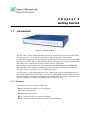
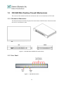
FW-3600 Series
Mini Desktop Intel IXP 42x
Network Security Platforms
User’s Manual
Copyright and Disclaimers
© Copyright 2004 - Lanner Electronics Inc.
All Rights Reserved
The contents in this publication have been thoroughly checked and considered accurate. The
publisher and manufacturer of this product, Lanner Electronics, is not responsible for any
violation of patents or other rights of third parties resulting from its use. Neither does Lanner
Electronics assume any responsibility for any inaccuracies contained in this manual, nor make
any commitment to keep the information in this document up-to-date.
Lanner reserves the right to make improvements to this document and/or this product at any
given time without notice.
No part of this document may be reproduced, stored in a retrieval system, or transmitted in any
form or by any means (electronic, mechanical, photocopying, recording, or otherwise, without
the formal consent from Lanner.
Trademark Acknowledgments
IXP is a trademark of Intel Corp.
All products and/or brand names stated in this publication are the trademarks of their rightful
and associated companies.
Radio Frequency Emissions Notice
This equipment has been tested and found to comply with the digital device limits pursuant to
Part 15 of the FCC Rules. These limits are designed to provide reasonable protection against
harmful interference when operate in a commercial environment. This equipment generates,
uses, and can radiate radio frequency energy and, if not installed and used in accordance with
the instruction manual, may cause harmful interference to radio communications. Operation of
this equipment in a residential area may cause harmful interference, in which case the user will
be required to correct the interference at his expense.
ii
Safety Instructions
The following information relates to the safety of installation and maintenance personnel. Read
all instructions before attempting to unpack, install or operate this equipment, especially before
connecting the power adapter.
Please keep the following in mind as you unpack and install this equipment:
Always follow basic safety precautions to reduce the risk of fire, electrical shock and
injury to persons.
Do not apply power into FW-3600 before installation or when disconnecting this
product from its original system setup.
Use only the specified power adapter (output voltage: 5VDC/3A) and make sure the
power adaptor’s plug matches your electrical wall outlet.
To prevent fire or shock hazard, do not expose the unit to rain, moisture or install this
product near water.
Locate a safe and dry location to place this product. Keep it away from wet
surfaces/surroundings.
Never push an object of any kind into this product through openings or empty slots, as
you may damage parts.
Do not attach the power supply cabling to building surfaces. Do not allow anything to
rest on the power cabling or allow it to be abused by persons walking on it.
Distance your working area from moist floors, ungrounded power extension cables, and
unavailable safety grounds.
Avoid installation of this product during a lighting storm.
Damages caused by electrostatic discharge may result in total or intermittent system
failures. To minimize the possibility of ESD damage, an anti-static strap is highly
recommended.
When cleaning or servicing this unit, avoid using highly toxic or aerosol cleaners. Use a
clean damp cloth when wiping its surfaces.
Do not place this device in a tight and sealed location. Place the unit where it can access
sufficient airflow to its vent holes (openings along its sides). Never block or cover these
openings.
Do not disassemble this product on your own.
iii
Getting Technical Assistance
Should you encounter questions or problems with your FW-3600, Lanner Electronics is ready
to assist you within the guidelines of our product support programs. First, check the electronic
product documentation for assistance. If you still cannot find the solution to your problem,
contact Lanner sales team with the following information handy:
FW-3600 model name
Part number
Local network configuration details
The abnormal behavior and/or error messages reported by your network system
Your questions, or a description of the problem you are experiencing
Call, fax, or e-mail Lanner Electronics for technical support.
Phone: 886-2-8692-6060
Fax: 886-2-8692-6101
E-mail: sales@lannerinc.com
About this Manual
This target audience of this manual includes users, administrators and technicians. This
publication is a useful reference when installing, configuring, operating and managing the
FW-3600. This breakdown and short descriptions of this manual’s contents are as follows:
Chapter 1 – Introduction provides an overview of the FW-3600 mini
desktop firewall platform, including its related features, application
usage and technical specifications list. The chapter also guides users
through the pre and post installation process by listing safety tips plus an
overall detailed description of the control board and system and their vital
components.
Chapter 2 – Image Download and Test Procedure points out the basic
steps when upgrading your FW-3600 via command line interface.
Appendix A – summarizes all drivers contained in the FW-3600 Drivers
and Documentation Disk.
iv
Table of Contents
Copyright and Disclaimers..................................................................................ii
Trademark Acknowledgments ............................................................................ii
Radio Frequency Emissions Notice....................................................................ii
Safety Instructions ............................................................................................. iii
Getting Technical Assistance ............................................................................iv
About this Manual..............................................................................................iv
Chapter 1 Getting Started.....................................................................................................1
1.1 Introduction................................................................................................ 1
1.1.1
Features ............................................................................................................................. 1
1.2 Technical Specifications............................................................................ 2
1.3 Packing Contents ...................................................................................... 3
1.4 EM-434 System Board .............................................................................. 3
1.4.1
1.4.2
1.4.3
1.4.4
Mechanical Dimensions ..................................................................................................... 3
Board Layout ...................................................................................................................... 4
Jumper Settings ................................................................................................................. 4
Connector Pin Assignments ............................................................................................... 4
PS4S1:4-Pin Power Connector (Small-4P) ........................................................ 4
GPIOA1:2x4 GPIO Pin Header.......................................................................... 5
EJC1: EJPROB Connector ................................................................................. 5
LANA1~ LANA3: Type 1 (RJ-45)..................................................................... 5
COMA1: RS-232 Serial Port #1 Connector (D-Sub) ......................................... 5
LAN4PA1: 4 x RJ-45 Ports ................................................................................ 6
PCIB1~2:124-pin Mini PCI Sockets .................................................................. 7
RSW1: 4-pin Software Reset Switch.................................................................. 8
RSW2: 4-pin Hardware Reset Switch ................................................................ 8
1.5 FW-3600 Mini Desktop Firewall Mechanisms ........................................... 9
1.5.1
1.5.2
1.5.3
Mechanical Dimensions ..................................................................................................... 9
Face Panel ......................................................................................................................... 9
Face Panel LED Status and Behavior............................................................... 10
Rear View......................................................................................................................... 10
Chapter 2 EM-434 Image Download................................................................................. 11
2.1 Pre-installed Linux Software.................................................................... 11
2.2 Boot-up Conditions.................................................................................. 12
2.3 Downloading Redboot ............................................................................. 14
2.3.1
2.3.2
Hardware Requisites ........................................................................................................ 14
Procedures ....................................................................................................................... 14
2.4 Downloading Linux and Ramdisk ............................................................ 15
2.4.1
Procedures ....................................................................................................................... 15
Appendix A Driver Information .........................................................................................16
Terms and Conditions
Warranty Policy
RMA Service
v
Chapter 1
Getting Started
1.1
Introduction
Figure 1 – FW-3600 Outlook
The FW-3600 is a mini desktop Intel IXP based firewall platform equipped with an Intel IXP
422/425 processor. A cost-effective and fanless solution of its kind, it comes with a
pre-installed Booting Code and Linux Kernel. Its onboard mini PCI slots are tested compatible
with any type of WiFi 802.11g card and IPSec VPN Accelerating card. Software porting on the
FW-3600 is fully compatible with Firewall/VPN Software Applications.
Based on Intel’s Xcale architecture, FW-3600 bundles a 64MB SDRAM and a 16MB NOR
Flash onboard. On top of these are additional features like three FastEthernet ports and one
four-port switch, two mini PCI slots for additional flexibility.
The FW-3600 is a promising platform on various applications including Residential Security
Gateway, Residential Security Wireless Access Point, SOHO/ROBO Firewall/VPN Network
Security Appliance, Wireless 4A (Authentication, Authorization, Accounting, Administration)
Gateway, Hot Spot Accentuation and Billing System, and many more.
1.1.1 Features
Listed below are the key features of FW-3600.
Intel IXP 42x series RISC core base platform
Fanless system design
Slim-desktop form factor
Two mini-PCI sockets for expansion purposes
Easy Image Download Procedure for Software Programming
1
1.2
Technical Specifications
Chassis:
− Construction: Bench top Chassis
− Chassis Material: SPCC 1.0T
− Chassis Color: PMS 877C
Control Board:
− EM-434
− Dimensions: 147mm x 209mm
Processor:
− Intel IXP425, 533MHz (FW-3600A)
− IXP422, 266MHz (FW-3600B)
Flash RAM: Onboard 16MB NOR Flash ROM
System Memory: Onboard 64MB SDRAM
Boot Loader: Redboot
Ethernet Connectors:
− One RTL8305SB switch (MII) with ONE four-port switch and ONE Fast Ethernet RJ45
− Two RTL8100B 10/100 Ethernet controller with two Fast Ethernet RJ45
PCI Interface: Two mini-PCI sockets onboard
Real Time Clock: Li battery
I/O Connectors:
− One DB-9 console connector
− Mini software reset button
Pin Header:
− One JTAG pin header
− Hardware reset button onboard
− 4-pin power connector onboard
LED Indicators: Power, Status (programmable by GPIO), Ethernet Ports 1-7
Power Supply:
− +5V 3A auto-switching AC power adapter
− One power jack, 5V/3A
− Input Voltage Range: 100~240 V
− Frequency Range: 50Hz~ 60Hz
Storage Temperature: -20oC~70oC
Operation Temperature: 0oC ~40oC
Relative Humidity: 5%~95%, non-condensing
System Dimensions: 235 x 161.9 x 37.6 mm
Device Weight: 1 kg
Certifications: CE/FCC
2
1.3
Packing Contents
Carefully unpack your package and make sure that you have the following items.
FW-3600 Firewall Platform
Console cable
1.8 meters long cross-over Ethernet cable
1.8 meters long straight-through Ethernet cable
Face panel name plate label
Power adapter
Drivers and User’s Manual Disk
If you find anything missing or damaged, promptly contact your dealer for assistance.
1.4
EM-434 System Board
EM-434 is the system board bundled with the FW-3600 firewall platform. The succeeding
sections list all EM-434 related jumper settings and connector pin assignments.
1.4.1 Mechanical Dimensions
Figure 2 – EM-434 Control Board Dimensions (units in mm)
3
1.4.2 Board Layout
Figure 3 – EM-434 Jumpers and Connectors
1.4.3 Jumper Settings
The onboard jumper settings of EM-434 are custom-tailored to fit the FW-3600 functionality.
Changing the jumper settings may result in system malfunction or unforeseen damages.
1.4.4 Connector Pin Assignments
PS4S1: 4-Pin Power Connector (Small-4P)
Pin No.
1
2
3
4
Description
5V
Ground
Ground
12V
4
GPIOA1: 2x4 GPIO Pin Header
Pin No.
Description
Pin No.
Description
1
3
5
7
GPIO14
GPIO7
GPIO6
GPIO5
2
4
6
8
GND
GND
GND
GND
EJC1: EJPROB Connector
Pin No.
Description
Pin No.
Description
1
3
5
7
GND
GND
GND
GND
2
4
6
8
EJTAG_TCK
EJTAG_TMS
EJTAG_TDI
EJTAG_TDO
LANA1~ LANA3: Type 1 (RJ-45)
Description
Pin No.
1
2
3
4
5
6
7
8
Fast E-Net
Giga Net
TX+
TXRX+
T45
T45
RXT78
T78
MD0+
MD0MD1+
MD2+
MD2MD1MD3+
MD3-
COMA1: RS-232 Serial Port #1 Connector (D-Sub)
Pin No.
1
2
3
4
5
6
7
8
9
Description
Data Carrier Detect (DCDA #)
Receive Data (RXDA)
Transmit Data (TXDA)
Data Terminal Ready (DTRA #)
Ground (GND)
Data Set Ready (DSRA #)
Request To Send (RTSA #)
Clear To Send (CTSA #)
Ring Indicator (RIA #)
5
LAN4PA1: 4 x RJ-45 Ports
Pin No.
1
2
3
4
5
6
7
8
9
10
11
12
13
14
15
16
17
18
19
20
21
22
23
24
25
26
27
28
29
30
31
32
41
42
Description
RX+
RXTX+
T45
T45
TXT78
T78
RX+
RXTX+
T45
T45
TXT78
T78
RX+
RXTX+
T45
T45
TXT78
T78
RX+
RXTX+
T45
T45
TXT78
T78
PORT1
PORT2
PORT3
PORT4
GND
GND
6
PCIB1~2:124-pin Mini PCI Sockets
Pin No.
Description
Pin No.
Description
1
3
5
7
9
11
13
15
17
19
21
23
25
27
29
31
33
35
37
39
41
43
45
47
49
51
53
55
57
59
61
63
65
67
69
71
73
75
77
79
81
TIP
8PMJ-3
8PMJ-6
8PMJ-7
8PMJ-8
LED1_GRNP
LED1_GRNN
CHSGND
INT-B
+3.3V
RESERVED
GROUND
CLK
GROUND
REO
+3.3V
AD31
AD29
GROUND
AD27
AD25
RESERVED
C_BE-3
AD23
GROUND
AD21
AD19
GROUND
AD17
C_BE-2
IRDY
+3.3V
CLKRUN
SERR
GROUND
PERR
C_BE-1
AD14
GROUND
AD12
AD10
2
4
6
8
10
12
14
16
18
20
22
24
26
28
30
32
34
36
38
40
42
44
46
48
50
52
54
56
58
60
62
64
66
68
70
72
74
76
78
80
82
RING
8PMJ-1
8PMJ-2
8PMJ-4
8PMJ-5
LED2_YELP
LED2_YELP
RESERVED
+5V
INT-A
RESERVED
3.3VAUX
RST
+3.3V
GNT
GROUND
PME
RESERVED
AD30
+3.3V
AD28
AD26
AD24
IDSEL
GROUND
AD22
AD20
PAR
AD18
AD16
GROUND
FRAME
TRDY
STOP
+3.3V
DEVSEL
GROUND
AD15
AD13
AD11
GROUND
- More -
7
Pin No.
Description
Pin No.
Description
83
85
87
89
91
93
95
97
99
101
103
105
107
109
111
113
115
117
119
121
123
GROUND
AD8
AD7
+3.3V
AD5
RESERVED
AD3
+5V
AD1
GROUND
AC_SYNC
AC_SDATA_IN
AC_BIT_CLK
AC_CODEC_ID1
MOD_AUDIO_MON
AUDIO_GND
SYS_AUDIO_OUT
SYS_AUDIO_OUT GND
AUDIO_GND
RESERVED
VCC5VA
84
86
88
90
92
94
96
98
100
102
104
106
108
110
112
114
116
118
120
122
124
AD9
C_BE-0
+3.3V
AD6
AD4
AD2
AD0
RESERVED-WIP
RESERVED-WIP
GROUND
M66EN
AC_SDATA_OUT
AC_CODEC_ID0
AC_RESET
RESERVED
GROUND
SYS_AUDIO_IN
SYS_AUDIO_IN GND
AUDIO_GND
MPCIACT
3.3AUX
RSW1: 4-pin Software Reset Switch
Pin No.
Description
1
2
3
4
Reset signal
GND
GND
GND
RSW2: 4-pin Hardware Reset Switch
Pin No.
Description
1
2
3
4
Reset signal
GND
GND
GND
8
1.5
FW-3600 Mini Desktop Firewall Mechanisms
This section of the manual describes the mechanical and device nomenclature of FW-3600.
1.5.1 Mechanical Dimensions
The illustration below identifies the physical measurements of the FW-3600. The measurement
unit used is in millimeters (mm).
Figure 4 – FW-3600 Chassis Dimensions (units in mm)
1.5.2 Face Panel
Figure 5 – FW-3600 Face Panel
9
Face Panel LED Status and Behavior
The following table lists and explains the behavior of each LED on the FW-3600 front panel.
LED
Power
Color
Green
Status
(programmable Green
via GPIO15)
Ethernet Ports
1~7
Green
Status
Description
On
Off
On
When FW-3600 power is switched ON
No power connected
When GPIO 15 is programmed and set to a value of
“0”
When GPIO 15 is programmed and set to a value of
“1”
Data packets are being transmitted or received
Linked/established Ethernet connection present
No existing Ethernet port connections to FW-3600
Off
Blinking
On
Off
1.5.3 Rear View
Figure 6 – FW-3600 Rear View
Console Port:
via the console port cable, this connector attaches FW-3600 to
the host PC
Fast Ethernet Ports:
Ethernet RJ-45 connector, connected to networking environment
using a RJ-45 Ethernet cable
DC Power Jack:
Power connector, connected to the power adapter packed with
the FW-3600
Faulty or improper use of the power adaptor may cause permanent
damage to the power supply and the FW-3600. Plug the adaptor to an
electrical wall outlet that matches its specifications.
10
Chapter 2
EM-434 Image Download
This chapter explains the procedures when configuring the FW-3600, including its OS and
applications. The following sections and each procedure are highly required to achieve your
technical requirements.
2.1
Pre-installed Linux Software
The pre-installed Linux Kernel in the FW-3600 has the following details:
Version No.: 02042004
Software and Hardware Port Matching:
OS
Ethernet 1
Ethernet 2
Ethernet 3
Ethernet 4
Ethernet 5
Hardware
LAN4PA1
LANA3
LANA1
LANA2
If one LAN card exists and installed on a mini PCI socket
Illustrated below are the FW-3600 factory default assignments.
Figure 7 – FW-3600 Factory Default Assignments
11
2.2
Boot-up Conditions
Once the FW-3600 console port is connected to a console PC, there will be two choices
available mid-way during the FW-3600 system boot up:
1 Enter OS (default): “1” allows access into FW-3600 OS and runs the firewall
2 Enter Redboot: “2” allows entry to Redboot for downloading of boot code / OS from
another PC via TFTP protocol.
The following figure shows the screen after choosing the option “1”.
After the OS completes boot up process, you can now open a browser from a connected PC to
view the Configuration Wizard that allows you to setup and configure your system. Enter the
following address on your browser to launch the Configuration Wizard:
http://192.168.1.254:8090
Follow the onscreen instructions to complete the process. Configure the WAN port type as
static and using the default settings.
12
The displayed screen will show the figure below after selecting option “2”.
13
2.3
Downloading Redboot
There are two standard boot code file names bundled with your FW-3600.
IXP422-based FW-3600: JFIXP266.exe
IXP425-based FW-3600: JFIXP533.exe
Downloading the Redboot is required when you intend to perform the following:
modify the existing Redboot,
replace the entire Redboot code, and
recover to original Redboot code of FW-3600.
2.3.1 Hardware Requisites
Before executing any command line, a JTAG cable must connected from the EM-434 control
board of FW-3600 to the parallel port of the console PC. To do this, follow the steps below.
1.
Remove the cover of FW-3600.
2.
Locate the designated connector, EJC1, onboard EM-434.
3.
Connect the pin connector at one end of the JTAG cable onto EJC1.
4.
Connect the parallel port connector of the JTAG cable onto the parallel port of the console
PC.
5.
Ensure and check the presence of a serial port connection (via console cable) from the
FW-3600 console connector to the console PC.
Reminder:
Redboot boot code download for modification/replacement/recovery
purposes requires FW-3600connection to a PC via TFTP protocol.
2.3.2 Procedures
After completing the hardware connections, you are now ready to download the Redboot code.
The following is an example of the download process under Windows 98.
From the Windows98 Start menu;
Open a Hyper terminal program
Configure the Baud rate as 115200, N,8,1, NONE
Run
c:> JFIXP266 Fem434aa.T06, then press <Enter>.
14
2.4
Downloading Linux and Ramdisk
Downloading of Linux and Ramdisk are only possible using the
RTL8305SB Ethernet port: LANA3.
Note:
The bundled Linux Kernel of FW-3600 is an open source architecture. This section is of vital
use for programmers who wish to set up the FW-3600 into a TFT server. Downloading of
Linux and Ramdisk are required when you intend to perform the following:
modify the existing Kernel,
replace the entire Kernel, and
recover to original Kernel of FW-3600.
Reminder:
Linux and Ramdisk downloads for modification/replacement/recovery
purposes require FW-3600 connection to a PC via TFTP protocol.
2.4.1 Procedures
From the TFTP server’s configured protocol, run the following command lines:
Setup a TFTP server
RedBoot> fconfig
set the local ip address and tftp server ip address based on your
preferred settings (mainly to configure FW-3600 as a TFTP server)
Reset the system (using the reset button the FW-3600 rear panel)
Use the following easy commands:
RedBoot>1 <Enter>
RedBoot>2 xxxx
(fis init –f)
(load -r -v -b 0x10000000 mac.bin) (xxxx = filename)
(fis create -b 0x10000000 -l 0x2000 mac)
RedBoot>3 Fem434aa.K01
(load -r -v -b 0x11600000 zImage)
(fis create -b 0x11600000 -l 0x100000 zimage)
RedBoot>4 Fem434aa.R01
(load -r -v -b 0x10800000 target.gz)
fis create -b 0x10800000 -l 0x600000 ramdisk)
RedBoot>5
fis create -b 0x100000 -l 0x2000 param
Reset the system using the reset button the FW-3600 rear panel)
15
Appendix A
Driver Information
This appendix contains a rundown of the drivers contained in the Drivers and User’s Manual
Disk. The drivers of each component are vital for programmers when developing their
proprietary kernels.
NOR Flash
DRAM
RealTek RTL8100B
RealTek 8305SB
Mini PCI Socket
RTC
16
Terms and Conditions
Date:2004.07.08
Warranty Policy
1.
All products are warranted against defects in materials and workmanship for a period of two years
from the date of your purchase.
2.
The buyer will bear the return freight charges for goods returned for repair within the warranty
period; whereas manufacturer will bear the after service freight charges back to user site.
3.
The buyer will pay for repair (for replaced components plus service time) and transportation
charges (both ways) for items after the expiration of the warranty period.
4.
If the RMA Service Request Form does not meet the stated requirement as listed on “RMA Service“,
RMA goods will be returned at customer’s expense.
5.
The following conditions resulting to the defective goods are excluded from this warranty:
A.
Improper or inadequate maintenance by the customer
B.
Unauthorized modification, misuse, or reversed engineering of the product
C.
Operation outside of the environmental specifications for the product.
RMA Service
1.
Requesting for a RMA#:
To obtain a RMA number, simply fill out and fax the “RMA Request Form” to your supplier.
2.
3.
Shipping:
A.
The customer is required to fill up the problem code as listed. If your problem is not among
the codes listed, please write the symptom description on the remark.
B.
Ship the defective unit(s) on freight prepaid terms.
C.
Mark the RMA # clearly on the box.
D.
Customer is responsible for shipping damage(s) resulting from inadequate/loose packing of
the defective unit(s).
E.
Use the original packing materials whenever possible.
All RMA# are valid for 30 days only:
RMA goods received after the effective RMA# period will be rejected.
RMA Service Request Form
When requesting RMA service, please fill out this RMA Service Request Form.
Without this form your RMA will be REJECTED!!!
□
Reasons to Return:
RMA No:
□
Repair(Please include failure details)
Company:
Contact Person:
Phone No.
Purchased Date:
Fax No.:
Applied Date:
Testing Purpose
Return Shipping Address:
□
Shipping by:
Air Freight□
Item
Model Name
Item
Sea□
□
Express
Serial Number
Problem Code
*Problem Code:
01:D.O.A.
02: Second Time R.M.A.
03: CMOS Data Lost
04: FDC Fail
05: HDC Fail
06: Bad Slot
Request Party
Others:
Configuration
Failure Status
07: BIOS Problem
08: Keyboard Controller Fail
09: Cache RMA Problem
10: Memory Socket Bad
11: Hang Up Software
12: Out Look Damage
Authorized Signatures / Date
13: SCSI
14: LPT Port
15: PS2
16: LAN
17: COM Port
18: Watchdog Timer
Confirmed By Supplier
19: DIO
20: Buzzer
21: Shut Down
22: Panel Fail
23: CRT Fail
24: Others (Pls specify)
Authorized Signatures / Date
PEXNSD01-040709
Version 1.0
Printed and published in Taiwan