1
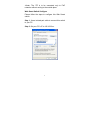
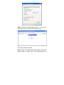
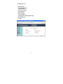
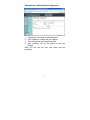
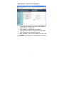
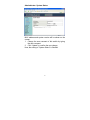
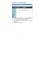
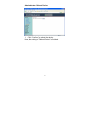
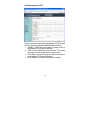
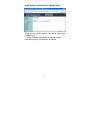
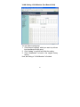
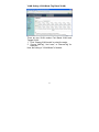
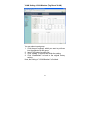
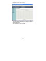
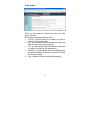
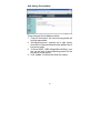
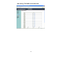
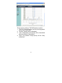
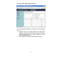
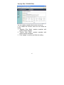
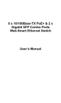
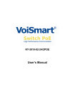
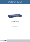
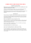
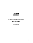
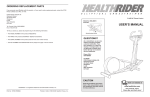
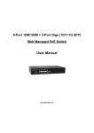
16-Port 10/100Base Fast Ethernet
Web-Smart PoE Ethernet Switch
User’s Manual
<Note> The ITE is to be connected only to PoE
networks without routing to the outside plant.
Web Smart Switch Configure
Please follow the steps to configure this Web Smart
switch.
Step 1: Use a twisted pair cable to connect this switch
to your PC.
Step 2: Set your PC’s IP to 192.168.2.xx.
1
Step 3: Open the web browser (like IE…), and go to
192.168.2.1 Then you will see the login screen.
ID and the password: admin
Step 4: After the authentication procedure, the home
page shows up. Select one of the configurations by
2
clicking the icon.
- Administrator
- Port Management
- VLAN Setting
- Per Port Counter
- Trunk Setting
- QoS Setting
- Security Filter
- Configuration Backup/Recovery
- Miscellaneous
- Logout
3
Administrator: Authentication Configuration
1.
2.
3.
4.
Change the user name and the password.
Click “Update” to confirm the new change.
Turn off the power and reset this switch.
After resetting, turn on the switch for the new
change.
Now, you can use the new user name and the
password.
4
Administrator: System IP Configuration
1. Change the IP address: type the new IP address or
select DHCP IP configuration.
2. Click “Update” to confirm the new change.
“Setting Process OK!!” will be shown on the screen.
3. Turn off the power and reset this switch.
4. After resetting, turn on the switch for the new
change.
Now, the setting of “System IP Configuration” is finished.
5
Administrator: System Status
MAC address and system version will be shown on the
screen.
1. Change the new comment of this switch by typing
the new comment.
2. Click “Update” to confirm the new change.
Now, the setting of “System Status” is finished.
6
Administrator: Load Default Setting
1. Click “Load” to back to the factory default setting.
2. Turn off the power and reset this switch.
3. After resetting, turn on the switch for the new
change.
Now, the default is loaded.
7
Administrator: Firmware Update
Follow the instruction on the screen to update the new
firmware.
Please contact with your sales agents to get the latest
firmware information.
8
Administrator: Reboot Device
1. Click “Confirm” to reboot the device.
Now, the setting of “Reboot Device” is finished.
9
Port Management: Port Configuration
Select the “Port No.” - configure the mode below:
1. “Auto”: enable/disable Auto-Negotiation function of
the port.
2. “Speed”: select the 10M or 100M mode of the port.
3. “Duplex”: select the port is full or half-duplex mode.
4. “Pause”: enable/disable the port.
5. “Backpressure”: enable/disable the backpressure of
the port.
6. “Tx Capability”: enable/disable TX capability of the
port.
7. “Addr. Learning”: enable/disable this function of the
port.
10
Port Management: Port Mirroring
Port Mirroring is used to mirror traffic, RX, TX or TX&RX,
from Source port to Destination port for analysis.
1. Select the Destination port: you can choose port 1
to port 16.
2. Select the Source port: by clicking the checking
box of the port.
3. Click “Update” to save the setting.
Now, the setting of “Port Mirroring” is finished.
11
Port Management: Bandwidth Control
1. Select the “Port No.”: you can choose port 1 to port
16.
2. “Tx Rate”: set the different transmission rate of this
selected port and choose the speed from 0~255
based on two speed levels.
3. “Rx Rate”: set the different receiving rate of this
selected port and choose the speed from 0~255
based on two speed levels.
4. Click “Update” to confirm the setting.
Now, the setting of “Bandwidth Control” is finished.
12
Port Management: Broadcast Storm Control
1. Set the threshold of per port to define the status of
broadcast packets.
2. Click “Update” to confirm the setting.
Now, the setting of “Broadcast Storm Control” is
finished.
13
Port Management: PoE
Remote access and monitor the attached PD (Powered
Device) status by using Enable/Disable function.
1. “Enable”: POE of the port is able to supply power to
the attached PD (Powered Device).
2. “PSE Current & Minimum Output Power”: The status
of the port current and minimum output power.
3. “POE class”: each POE port will detect the class of
the attached PD (Powered Device).
4. Click “Update” to confirm and finish the setting.
14
VLAN Setting: VLAN Mode (Port Based VLAN)
There are two VLAN modes: Port Based VLAN and
Tagged VLAN.
1. Click “Change VLAN mode” to select the mode.
Now, the setting of “VLAN Mode” is finished.
15
VLAN Setting: VLAN Member (Port Based VLAN)
You can select a port group.
1. Click the port numbers: which you want to put them
into the selected VLAN group.
2. Click “Update” to confirm and finish the setting.
3. Click “LoadDefualt” to back to the original factory
setting.
Now, the setting of “VLAN Member” is finished.
16
VLAN Setting: VLAN Mode (Tag Based VLAN)
There are two VLAN modes: Port Based VLAN and
Tagged VLAN.
1. Click “Change VLAN mode” to select the mode.
2. Choose “AddTag”, “don’t care”, or “RemoveTag” for
each port.
Now, the setting of “VLAN Mode” is finished.
17
VLAN Setting: VLAN Member (Tag Based VLAN)
You can select a port group.
1. Click the port numbers: which you want to put them
into the selected VLAN group.
2. Input PVID Index for each port.
3. Click “Update” to confirm and finish the setting.
4. Click “LoadDefualt” to back to the original factory
setting.
Now, the setting of “VLAN Member” is finished.
18
VLAN Setting: Multi to 2 Setting
This is a special design for easily setting the switch
VLAN into “VLAN Per Port“.
1. Choose “Destination Port No”.
2. Choose “Disable Port”.
3. Click “Update” to confirm and finish the setting.
After this setting, all ports can only connect to the
destination port.
19
Per Port Counter: Port Counter
You can read the transmitting and receiving packet of
the connecting port.
Click “Refresh” or “Clear” the data.
20
Trunk Setting
There are two groups to choose and max. for each
group is 4 ports.
Set up port trunk group mode as below:
1. “Port ID”: you can select port number you want to
include into the same group.
2. “SA”: you can select Source Address of the port you
want to include into the same group.
3. “DA”: you can select Destination Address of the port
you want to include into the same group.
4. “SA & DA”: you can select both Source Address and
Destination Address of the port you want to include
into the same group.
5. Click “Update” to confirm and finish the setting.
21
QoS Setting: Priority Mode
There are three Priority Modes to select.
1. “First-In-First-Service”: the first receiving packet will
be firstly transmitted.
2. “All-High-before-Low”: packets set in high priority
mode will be firstly transmitted before packets set in
low priority mode.
3. “4 Queue WRR”: WRR (Weight-Round-Robin), you
can set the ratio of the transmitting packet for the
low priority to high priority.
4. Click “Update” to confirm and finish the setting.
22
QoS Setting: Class of Service Configuration
You can set QoS mode of per port by different bases.
1. “Port Base”: you can select the port which you want
to configure as high priority. It means the packet of
the port will be firstly transmitted.
2. “VLAN Tag”: you can select the port which you want
to configure as packets. It means the packet with
special Tag will be firstly transmitted.
3. “IP/DS”: you can select the port which you want to
configure as packets. It means the packets with
special IP will be firstly transmitted.
4. Click “Update” to confirm and finish the setting.
23
QoS Setting: TCP/UDP Port Number QoS
24
There are four modes of TCP/UDP priority to select.
1. “F-I-F-O”: First-In-First-Out, the first receiving packet
will be firstly transmitted.
2. “Discard”: packets will be discarded.
3. “Low”: the packets of low priority will be transmitted
after the packets of high priority.
4. “High”: the packets of high priority will be firstly
transmitted.
25
Security Filter: MAC Address Filter
Set special MAC address to activate on the selected
port.
1. Enable: allow the packet which has this MAC
address to activate on the port. The port will record
the first receiving source MAC address as the
security MAC address.
2. Click “Update” to confirm and finish the setting.
26
Security Filter: TCP/UDP Filter
You can enable or disable this function of per port.
If you enable this function, there are two modes as
below,
1. “Negative Filter Mode”: packets compliant with
protocol will be dropped.
2. “Positive Filter Mode”: packets compliant with
protocol will be forwarded.
3. Click “Update” to confirm and finish the setting.
27
Configuration Backup/Recovery
Follow the instruction on the screen to update the
original setting.
“Backup”: Click “Download” to confirm the setting.
“Recovery”: Click “Update” to confirm the setting.
28
Miscellaneous
1.
2.
3.
4.
“Aging Time”: You can set queue aging time into
different milliseconds or disable this function.
“VLAN Striding”: You can enable/disable this
function.
“IGMP Snooping”: You can enable/disable this
function.
Click “Update” to confirm and finish the setting.
29
Logout
You can click “Accept” to logout.
30