1
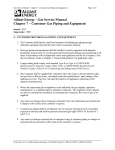
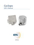
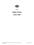
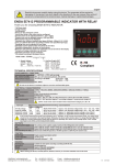
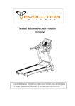
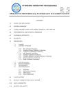
WORLDWIDE CORROSION ENGINEERING DOC. NO:TCS-O63-50V-50A-3P-440 DOCUMENT SUBJECT: Manual Controlled CP Rectifier User Manual Page 1 of 28 MANUAL CP RECTIFIER (50V / 50A) (63 Manual Voltage Controlled- Oil Natural) USER MANUAL Nov 2010 6 1 REV As-Built DESCRIPTION M.E PREPARED C.A.B. CHECKED A..C.B. APPROVED 04/08/10 DATE WORLDWIDE CORROSION ENGINEERING DOC. NO:TCS-O63-50V-50A-3P-440 DOCUMENT SUBJECT: Manual Controlled CP Rectifier User Manual CONTENTS 1. INTRODUCTION 2. SCOPE 3. CODES 4. SYSTEM COMPONENTS 5. HANDELING & INSTALLATION 6. COMMISSIONING 7. OPERATION MODES 8. RECOMMENDATIONS APPENDIX-1. Major Components APPENDIX-2. Wiring Diagram APPENDIX-3. Mechanical Details DECLARATIONS AND WARRANTY Page 2 of 28 WORLDWIDE CORROSION ENGINEERING DOCUMENT SUBJECT: Manual Controlled CP Rectifier User Manual 1. DOC. NO:TCS-O63-50V-50A-3P-440 Page 3 of 28 INTRODUCTION A DC Power equipment such as transformer rectifier supplies current that is applied for Cathodic Protection of buried or immersed metal structure. The transformer rectifiers (TR) are normally used when AC power from the mains is available. Hi-Tec's Manual Cathodic Protection TR Units ( Oil-Cooled ) are specially designed for safe and long term operation in environments such as desert and tropical locations. The transformer rectifier components are housed in steel enclosures divided into two main sections, namely oil tank and control cabinet. The transformer rectifier is supplied complete with bolted type base frame and fixing bolts for plinth mounting. The outdoor control cabinets are normally provided with sunshade. STANDARD FEATURES OF THE 63 STEP MAUAL CONTROLLED RECTIFIERS 1) Manual Voltage Control over the 63 steps of Nominal rated voltage Automatic 2) Coarse, Medium and fine adjustment by 3 X 4 step tap changer switches, rated to operate while system is energized, even on full load condition. 3) Compact design and easy to use and installation . 4) Minimum maintenance requirements and long operation time. 5) Weather Proof construction and corrosion resistive finish with UV protection. 6) AC input voltage, DC output voltage and current monitoring by moving coil analogical meters. 7) Over voltage and current protection for both of AC and DC sides. 8) Surge Protection on D.C. side, lightning protection on Ac side. 9) Cooling by Natural Convention of Transformer Oil. 10) Suitable for either 3 Wire or 4 wire connection for 3Phase 380/440 Volt 50 and/or 60 Hz systems. WORLDWIDE CORROSION ENGINEERING DOCUMENT SUBJECT: Manual Controlled CP Rectifier User Manual 2. DOC. NO:TCS-O63-50V-50A-3P-440 Page 4 of 28 SCOPE Transformer Rectifier, A DC power source to rectify an alternating current into a stabilized (voltage and current) direct current. The output voltage and current can be regulated to meet rated Impressed Current Cathodic Protection System requirements, which normally defines by client/contractor CP specialist and designers. The Scope of this documents is to descript details of 63 Step Manually Controlled Cathodic Protection trans/rectifier unit (TR) and to be a guide line of Installation, commissioning, Operation and maintenance of the system which could be summarizes within the following details; a) b) c) d) a) b) c) d) e) f) g) h) i) j) k) l) Input Voltage : 440 VAC (396/484 V) , Three Phase at 50 Hz Input Frequency variation : ±05 % Output voltage : From 0-50 Vdc Output Current : From 0-50 Adc Cooling : Oil-Cooled ( Natural Convention) Operating Modes: Manual Voltage Regulation, None Continues Operation by Timer Interrupter Control : Manual compensation of output voltage, by 3X4 Position tap changer switch. Compensation: 3 Nos of 3 way 4 position switches ( Coarse, medium, fine) giving control over 63 steps of output voltage that could be adjusted via Auto transformer (T1) which have been linked to the Primary of main double wounded Transformer (T2) to change the input of T2 from 0 up to Nominal rated input voltage. Rectification : Full wave Silicon diode Ambient temperature: 0 up to 55ْ C Shade Temperature. Location : Outdoor, 0 to 2500 meters altitude Protection: - Overload and short circuit protection by Input circuit breaker (thermo-magnetic) DC output and Rectification and fuses, - Over voltage and Surge protection on DC side and lighting protection on AC and DC sides. - Over heat Protection by Oil Temperature Sensor - Oil Leakage protection by Oil Level Sensor Indicators: - DC output voltage analogical meter, - DC output Current and AC input voltage analogical meter, - Oil Level Gauge - Dial Type Oil Temperature indicator - AC mains, Oil level, Oil Temperature failure Transformer: Double wounded, Class F, min of 95% efficiency Ingress Protection : IP-55 Safety : Conforming EC safety Directives WORLDWIDE CORROSION ENGINEERING DOC. NO:TCS-O63-50V-50A-3P-440 DOCUMENT SUBJECT: Manual Controlled CP Rectifier User Manual Page 5 of 28 Table-1. Details of TR unit o o Environmental Condition Ambient temp: max +55 C min -20 C Humidity: 98 % Double Wound Transformer Rating Ph: 3 Frequency: 50 Hz Area Description Altitude: 0~2500 m above sea level Ex-Proof Safe Indoor Outdoor Control Panel : IP55 Oil Tank : IP55 Apparent Power: 3.5 KVA Active Power: 3.34 KW Primary input voltage: 440 V Primary input current: 5 A Second output voltage: 50 V Second output current: 50 A Isolation : Double wounded Electro static shield: 2.5 K V Temperature class : F Maximum Inrush current: 10A Measuring Instruments Measurement device Analogue Digital AC Input Voltmeter scaled from 0 to 500 V AC input Ammeter scaled from to A DC output Voltmeter scaled from 0 to 60 V DC output Ammeter scaled from 0 to 60 A o Oil Temperature meter scaled from 0 to 120 C Reference cell voltage scaled from to V Reference cell Type : N/A Reference cell Qty: N/A Connectivity : RS232 RS485 GSM Wireless Protections Protection Cooling Mounting Finishing AN ONAN INAF Pole mounted Plinth mounted Wall mounted Freestanding Surface Preparation: Sand Blast SA 2.5 Primer:cold galvanized by zinga Dimensions Finish : modify poly urethane Width:1100 mm Height:1600 mm Depth: 1260 mm Oil capacity: 230 lit Net Weight: 420 kg ELECTRICAL CHARACTERISTICS AC Input Ph:3 Current:5 A Voltage: 380/440 rating DC Output Rating & Control type Rectifying Unit Timer circuit Intervals Terminals Auxiliaries & Accessories Frequency: 50 Hz 5% Voltage: 50 V Current: 50 A DC output control: manual Auto Constant voltage Constant Current Reference potential control Manual Voltage Controlled Stack elements Selenium Silicon Rectification Mode: Full Wave Ratings: 3P, Full-bridge, 6 Pulse External Internal □ Internal Synchronized Internal None Synchronized Cos : 0.95 Input MCCB Rectifier HRC fuse Output HRC fuse Voltmeter fuse Controller fuse Overload protection by HRC TR TEST RESULTS Transformer Insulation Test References Prime & Yoke Sec & Yoke Prime & Sec Test Value > 2 KVAC >2 KVAC > 2 KVAC 50Hz 50Hz 50Hz Result < 5 mA < 5 mA < 5 mA TR Load ability test Iin Vin Pin Iout Vout Pout % 50% Load ON: 3-200 Sec OFF: 3-200 Full Load Sec AC : 3 M6 Alan Stud type Terminal, DC Outgoing: 2 M8 Stud type Terminal Induced filter Capacitive filter FWD Surge Protection (AC and DC sides) Sunshade silica gel breather Lifting Hugs Oil drain Valve, Oil level Indicator WORLDWIDE CORROSION ENGINEERING DOC. NO:TCS-O63-50V-50A-3P-440 DOCUMENT SUBJECT: Manual Controlled CP Rectifier User Manual 3. Page 6 of 28 CODES TR units are under manufacturing and testing meeting recognized standards and regulations of Cathodic protection and electrical and electronic system and devices. a) BS 7361 b) IEC 60051 c) d) e) f) IEC 60439-1 IEC 60076 BS 2914 IEC 60144 g) h) i) j) k) l) m) IEC 60146 IEC 60269 IEC 60391 IEC 60445 IEC 60529 IEC 60117 IEC 61024 Cathodic Protection Recommendation for Indicating Electrical Measuring Instruments and Their Accessories Low voltage switchgear and control gear assemblies Power Transformers Surge Diverters Degree of Protection of Enclosures for Low Voltage Switchgear and Control Gear Semiconductor Converters Low Voltage Fuses Marking of Insulated Conductors Identification if Apparatus Terminal Marking Using an Alphanumeric Notation Classification of degrees of protection provided by Enclosures Recommended Graphical Symbols Protection of structures against lightning TR unit is also meeting all of the equivalent EN and BS standards, directives and recommendations 4. SYSTEM COMPONENTS WORLDWIDE CORROSION ENGINEERING DOCUMENT SUBJECT: Manual Controlled CP Rectifier User Manual DOC. NO:TCS-O63-50V-50A-3P-440 Page 7 of 28 The transformer-rectifier (TR) have been composed of separated sections ; Control Cabinet Consist of Metering and Control devices. The AC Terminal Cabinet. Consist of AC terminal with Protection & Auxiliary devices. The DC Terminal Cabinet. Consist of DC Terminal with Protection & Auxiliary devices. Oil Tank Consist of Auto-Transformer (T1), Step-down transformer (T2), Rectification Unit and Filter. Maintenance Cabinet A special tool and document container with a 240V AC socket to provide single phase AC power for maintenance proposes The Oil Tank is a heavy duty welded steel enclosure. A top steel enclosure consists of Terminal Cabinet, Control Cabinet and Maintenance Cabinet along the Chaise for installation of all oil immersed components is bolted and sealed to the top of the Oil Tank. An Auto-Transformer, main step-down transformer, rectifier unit and all components producing heat loss are fixed on fabricated steel chaise. The Top enclosure has a front Control Cabinet and AC/DC Terminal Cabinets on sides along the Maintenance Cabinet on the rear side. An Auto-Transformer, main step-down transformer, rectifier unit and all components producing heat loss are fixed on fabricated steel chaise to immerse all of the components producing heat loss while have been bolted on the top of the Oil Tank. Hinged pad lockable door of the Control Cabinet on the Front of Top Enclosure which have a viewing window of toughened glass to facilitate readings of the meters without opening the door, allows the user to easily access to the all of the controls and metering devices such as tap changer switch, panel meters and built-in timer interrupter unit. 4.1. The Control Cabinet Hinged pad lockable door with quick release toggle latches of the Control Cabinet on the Front of Top Enclosure which have a viewing window of toughened glass to facilitate readings of the meters without opening the door, allows the user to easily access to the all of the controls and metering devices such as tap changer switch, panel meters and built-in current interrupter & System monitor unit. The Metering device such as DC Voltmeter, DC Ammeter, AC input signal Lamps, Metering fuses and 2 pares of Plug-in for external Voltmeter/Ammeter along controls for built-in Current Interrupter & System Monitor Unit, have been installed on a internal hinged door, while the Controls of Tap changing switches have been installed on a 45 degree angular support on the bottom of Top Enclosure. WORLDWIDE CORROSION ENGINEERING DOC. NO:TCS-O63-50V-50A-3P-440 DOCUMENT SUBJECT: Manual Controlled CP Rectifier User Manual Page 8 of 28 Figure-1. Control & Measuring Instruments Front & Side View (Accessible via Control Cabinet door on front side of Top enclosure) WORLDWIDE CORROSION ENGINEERING DOCUMENT SUBJECT: Manual Controlled CP Rectifier User Manual 4.1.1. DOC. NO:TCS-O63-50V-50A-3P-440 Page 9 of 28 Control Devices The following devices are providing the full range of controls on nominal operational parameters of TR; Phase Selection Switch (ST3) 5 Position switch, used to Apply line voltages sequentially to the AC input Voltmeter (MT3) Coarse Adjustment Switch (S1). 3 ways 4 Position switch, used to select one of the positions on Auto winding of Control AutoTransformer (T1) which have been divide on 4 coarse taps. Medium Adjustment Switch (S2). 3 way 4 Position switch, used to select one of the positions on Buck winding of Control AutoTransformer (T1) which have been divide on 4 Medium taps. Fine Adjustment Switch (S3). 3 way 4 Position switch, used to select one of the positions on Buck winding of Control AutoTransformer (T1) which have been divide on 4 fine taps. Current Interrupter & System Monitor (INT). Used to provide controlled interruption on rectifier output via solid stated relay (SSR) in Timer mode & while any System failure would be happened. 4.1.2. Measuring Instruments While the following devices used to monitor the actual operational values; AC Phase Signal Lamp Indicators Used to Check the existence of AC input Power An AC Voltmeter (MT3) 72X72 mm Used to Monitor actual AC Input voltage between 2 pair of input phases. A DC Voltmeter (MT2) 72X72 mm Moving Coil Analogical Panel Meter Used to Monitor actual DC output voltage of TR to Anode/ Cathode Circuit. A DC ammeter (MT1) 72X72 mm Moving Coil Analogical Panel Meter Used to Monitor actual DC output Current of TR to Anode/ Cathode Circuit. The DC Output voltage and current a measuring instruments of the TR unit conform to IEC 60051 standard Recommendation for Indicating Electrical Measuring Instruments and Their Accessories. WORLDWIDE CORROSION ENGINEERING DOC. NO:TCS-O63-50V-50A-3P-440 DOCUMENT SUBJECT: Manual Controlled CP Rectifier User Manual 4.1.3. Page 10 of 28 Current Interrupter & System Monitor Unit (INT) INT unit is a combined Control and monitory device; Current Interrupter ON/OFF Switch (ST2). Used to switch between Continues and None continues Operations modes of TR unit. Set ON Time One Turn Potentiometer (PS1) Used to set ON Time period (form 3-200 S) for None continuous Operation mode Set OFF Time One Turn Potentiometer (PS2) Used to set OFF Time period (form 3-200 S) for None continuous Operation mode Interrupter Operational Indicator (LED1) Red Or Green 2 way LED lamp, Emitting Red during the off time period and Green while the rectifier applies current while operating on Timer mode only. on while ST2 is in TIMED position to indicated TR operates on None continues mode. Phase status signals (LED2, LED3, LED4) Green LED lamps, Emitting while input mains are exist. Failure on each phase will result LED5 to emits red AC input Fault signal. Phase status signals (LED5, LED6, LED7) Red LED lamps, Emitting sequentially while any Failure on irregular AC input mains or oil level reduction and oil Temperature rises with providing Potential Free Contacts to SCADA. Figure-2. Current Interrupter & System Monitor unit WORLDWIDE CORROSION ENGINEERING DOCUMENT SUBJECT: Manual Controlled CP Rectifier User Manual DOC. NO:TCS-O63-50V-50A-3P-440 Page 11 of 28 WORLDWIDE CORROSION ENGINEERING DOC. NO:TCS-O63-50V-50A-3P-440 DOCUMENT SUBJECT: Manual Controlled CP Rectifier User Manual Page 12 of 28 4.2. The Terminal Cabinets The Terminal Cabinets have been installed on left & right sides to provide separated connection for AC and DC connections. 4.2.1. AC Terminal Box This box have been fixed on the right side of control cabinet to maintain required connections and protection for incoming AC supply line. Following devices are accessible via this box; AC input Terminal (R, S, T, N) Suitable to connect 3 Wire or 4 Wire AC supply to the rectifier Main Thermo-magnetic Circuit Breaker (MCCB) Mechanical, Thermal and Magnetic Actuated main input switch to On/Off the rectifier and maintain Thermo-Magnetic over current protection of TR mains. AC side Surge/ Lightning Arresters ( SD1, SD2, SD3) Suitable rated spark gaps to protection the TR input from unwanted AC surges and lightning strikes and possible transient over voltage sparks of supply lines. Figure-3. AC Terminal Box Details and Components (Located on right side of top enclosure) WORLDWIDE CORROSION ENGINEERING DOC. NO:TCS-O63-50V-50A-3P-440 DOCUMENT SUBJECT: Manual Controlled CP Rectifier User Manual 4.2.2. Page 13 of 28 DC Terminal Box This box have been fixed on the right side of control cabinet to maintain required connections and protection for incoming AC supply line. Following devices are accessible via this box; DC Output Terminal (PIPE/STRUCTURE, GROUNDBED) Suitable rated 3 Blue Negative & 3 Red Positive Terminals Main Thermo-magnetic Circuit Breaker (MCCB) Mechanical, Thermal and Magnetic Actuated main input switch to On/Off the rectifier and maintain Thermo-Magnetic over current protection of TR mains. DC Side Surge/ Lightning Arresters ( SD4) Suitable rated spark gaps to protection the TR output from unwanted surges and lightning strikes and possible transient over voltage sparks to Cathode/Anode circuit. Figure-4. DC Terminal Box Details and Components (Located on Left side of top enclosure) Various levels of protection recommended by International standards such as IEC and EC have been provided for TR Units. WORLDWIDE CORROSION ENGINEERING DOCUMENT SUBJECT: Manual Controlled CP Rectifier User Manual DOC. NO:TCS-O63-50V-50A-3P-440 Page 14 of 28 A) Over intensities MCCB (Mould Cast Circuit breaker ) module which operates on both of thermal and magnetic intensities of over current effects on AC side have been provides to protect TR input stage. The MCCB module; a. Hold 100% of rated load; b. May trip between 101% and 124% of rated current; c. And must trip at 125% rated current or above. Suitable rated HRC fuses (Marked as HRC1, HRC2, HRC3 for Rectification/Transformer secondary and HRC4 for DC output) have been provided on both of rectification and output stages of TR unit, those Conform to IEC 60269 Low Voltage Fuses. B) Personnel Safety EC safety Directives have be applied to TR unit to prevent direct contacts of human and operator to AC supplied voltage. All metallic parts have been electrically continuous and one Earthing/Grounding terminal will allow their connection to an external earth circuit. An external ground M8 stud ground terminal (corrosion resistant) has been provided to be linked 25 sq. mm copper ground conductor. An internal equipment-grounding terminal adjacent to the AC terminal block has been also provided to earth all of the auxiliaries. C) Over Voltages Protections The Surge arresters connected between the anode and Cathode Terminals and AC input of the TR unit Conforms BS 2914 Surge Diverters. Additional Metal oxide varistors have been installed in parallel to the diode bridge rectifier 4.3. The Oil Tank The Oil Tank which conform to a NEMA 8 with Ingress protection to IP55 rating at least, will be fabricated from minimum of 2.5 mm thick (which exceeds 11-gauge) steel sheet conforming to ASTM A36 . Oil tank seams have been welded on the outside with continuous filet weld according to the latest edition of AWS D.1.1. Accessible seams inside of the Oil Tank have been also welded with continuous filet weld. Plinth montage and standing on ground have been provided for TR unit, within welding two 5 mm thick structural channels under the Oil Tanks bottom. Minimum of 100 mm type channels have been used for underside clearance. Suitable inner and outer reinforcements have been provide to prevent warp age during the construction, welding of oil tank. The top side of oil tank have suitable channel and bolting facilities to be fixed to the Top Enclosure to act as a hosing shell to allow the oil immersion of all the power components producing heat loss, mounted and fixed under the Top enclosure fabricated steel chaise such as Auto-Transformer, main step-down transformer, rectifier unit output filter and ect. WORLDWIDE CORROSION ENGINEERING DOC. NO:TCS-O63-50V-50A-3P-440 DOCUMENT SUBJECT: Manual Controlled CP Rectifier User Manual Page 15 of 28 An external Oil level site glass to make the cooling oil level and the recommended oil level visible during normal operation of the rectifier has been provide along a minimum 2" dia. Dial Type Thermometer on the front top side of the Oil Tank. An oil fill pipe (minimum 1.5 in I.D) with threaded cap on rear top side, and an accessible drain gate valve with a threaded outlet and galvanized steel plug placed at the lowest area of the rear side of the tank have been provided to remove oil and drain moisture. The drain valve have been also protected and shielded by surrounding thick plates extended to the end of the valve on each side. A suitable sized Silicagel Breather is also placed to the top same side of the oil tank. 4.3.1 Rectification unit Rectification have been performed by a 3 phase full bridge connection of silicon diodes which reverse tension are above 1200 V and conforms to IEC 60146 Semiconductor Converters. Power rectifying diodes have been mounted on anodized aluminum heat sinks and sized for temperature of 55 C degree ambient and rated load. The Diodes have been selected to comply to the minimum of 50% greater than the full rated rectifier output. 4.2.1. Step-Down Transformer T2 Double wounded Step-down Transformer have been rated for Magnetic wire and insulation materials to comply to minimum of Class F insulation within minimum of 95% of efficiency to provide Lowered AC voltage to the rectification form the incoming AC leads of the T1 auto-transformer. Copper earth shield have been provided between primary and secondary winding to provide appropriate earthing requirements. The Transformer unit complies to IEC 60076 Power Transformers recommendations. 4.4. Finishing After degreasing and Chemical cleaning the surface preparation will followed up by shut blasted process and the following finish will be applied; Cold Galvanized by Zinga® Epoxy Polyamide Modify Polyurethane TDFT Color Shade to be RAL 7033 Cement Gray Min 75 micro-meters Min 80 micro-meters 40~50 micro-meters 195~205 micro-meters WORLDWIDE CORROSION ENGINEERING DOC. NO:TCS-O63-50V-50A-3P-440 DOCUMENT SUBJECT: Manual Controlled CP Rectifier User Manual 5. Page 16 of 28 HANDELING & INSTALLATION The designated location for installation shall be verified on site prior to installation works taking place. The mounting details should conform to the details of plinth mounting channels under the Oil Tanks bottom of TR units which have been defined on this document. Bottom View Following procedure should be followed in given order 5.1. Check Check outside of TR unit on transport damage, if so please contact the supplier before continuing installation. 5.2. Mounting WORLDWIDE CORROSION ENGINEERING DOCUMENT SUBJECT: Manual Controlled CP Rectifier User Manual DOC. NO:TCS-O63-50V-50A-3P-440 Page 17 of 28 Place the TR Unit on the specified location Control panel shall faced to North always; Secure the TR Unit with the appropriate fixing materials; Make sure no foreign objects are located within 50 cm of TR Unit; Install the air Silicagel Breather; Secure the oil drain valve with a suitable end cap. Control panel shall faced to North always to reduce direct sunlight emission to control panel. 5.3. Coating inspection Check outside of TR unit on coating damage, if so please treat area immediately with a zinc cure 5.4. Installing cables WORLDWIDE CORROSION ENGINEERING DOC. NO:TCS-O63-50V-50A-3P-440 DOCUMENT SUBJECT: Manual Controlled CP Rectifier User Manual Right Side View (Showing AC input and Earth connection) Page 18 of 28 Left Side view (Showing DC inputs of Anode and Cathode Circuit) It shall be assured that the applicable AC breaker at the associated sub-station is locked off prior to connecting TR unit. Connect the earth terminal to an appropriate earth facility; Install all necessary cables properly; Route the AC supply cable from conduit to AC Terminal Box and follow the same for DC negative (Cathode/Structure) and DC positive (Anode/Groundbed) Cable(s) to DC Terminal box; Seal the entry of each Conduit within mastic of Polyurethane spray seal. 5.5. Connections Connect the Anode and Cathode cables to the output terminals with the correct polarity; DC Terminal Arrangement WORLDWIDE CORROSION ENGINEERING DOC. NO:TCS-O63-50V-50A-3P-440 DOCUMENT SUBJECT: Manual Controlled CP Rectifier User Manual Page 19 of 28 Connect the AC cable to the input terminals; AC Terminal Arrangement It shall be assured that the supplied line voltage is in conformity with the one specified on the rating plate of the TR unit. If any of the above listed instructions is not completed satisfactorily, please do not activate TR unit before consulting supplier. Faulty connections can cause serious failures in operation or damage to the TR unit. 5.6. Sunroof Mount sunroof on top of TR unit to protect the unit against direct sunlight and rain. WORLDWIDE CORROSION ENGINEERING DOCUMENT SUBJECT: Manual Controlled CP Rectifier User Manual 6. DOC. NO:TCS-O63-50V-50A-3P-440 Page 20 of 28 COMMISSIONING 6.1. Transformer oil The main power components of the TR unit are immersed in transformer oil. Immediately on-site the TR unit should be filled with a BS-148 / IEC 60296 Transformer oil. It shall be assured that the applicable AC breaker at the associated sub-station is locked off prior to filling TR unit. It is advisable to install first the TR unit before continuing. Never energize the TR unit without the transformer oil. To fill transformer oil inside the TR unit oil tank follow the below steps; Remove oil filler cap & gasket; Install a hose in the tank; Fill the tank until the oil level reaches 1/3 of the oil level indication; Remove the hose from the tank; Reinstall the gasket & oil filler cap. After a few hours the oil level can drop, due to release of air bubbles from the oil. Add oil if necessary. Maximal oil level can be exceeded due to high ambient temperatures. Depending on humidity and temperature the transformer oil can deteriorate. To prevent deteriorating of the oil use a silica gel dehumidifier, Never penetrate the oil tank more then 15 cm. To Drain transformer oil follow the below indicated steps; Remove oil filler cap; Remove the cap from the oil drain device; Connect suitable pipe to oil drain device; Then connect the pipe to the oil-regenerator station; Turn the spindle with a spanner to open en close the drain; Remove pipe and reinstall the cap onto the oil drain device. WORLDWIDE CORROSION ENGINEERING DOC. NO:TCS-O63-50V-50A-3P-440 DOCUMENT SUBJECT: Manual Controlled CP Rectifier User Manual 6.2. Page 21 of 28 Silicagel Breather To ensure the transformer oil keeps it optimal condition, a silicagel breather should be installed. During cooling down or heating up of the oil, the tank is breathing air in and out. The silica gel dehumidifies this air. To install the breather follows the below steps; Place gasket and the dehumidifier on the tank Install metal-guard/rating plate To Re-fill the silicagel cartridge follow the below steps; Remove cap of the dehumidifier (2); Fill container with the silica gel; Take out the oil reservoir (1); Place the oil reservoir back and fill it with oil3; Close the dehumidifier. Depending on humidity and temperature the silicagel shall deteriorate. At the start the gel is dark orange ( Or Dark Blue), during saturation the gel becomes lighter. Replacement should take place before the gel is almost white. Silicagel should be check regularly on its condition/color to prevent deterioration of the transformer oil. WORLDWIDE CORROSION ENGINEERING DOCUMENT SUBJECT: Manual Controlled CP Rectifier User Manual DOC. NO:TCS-O63-50V-50A-3P-440 Page 22 of 28 6.3. Energizing Prior to energizing the following steps should be followed and the results should be satisfactory. If any problems occur during this procedure, energizing should not take place and the supplier should be contacted. Onsite situation is stable and safe; Oil drain valve is closed and secured; Oil tank is filled to the given level with transformer oil (See §6.1); Air silicagel Breather is installed and filled with silica gel (See §6.2); Check if DC-circuit is properly installed and not causing short-circuiting; Check if TR unit is connecter to an AC power circuit in accordance to the rating plate information; Check all cable glands are installed correct; Make a full visual inspection to assure TR unit is in an optimal state; Rotate Manual Voltage Control Switches (S1, S2 and S3) to Position Marked 1. When all precautions are taken and satisfactory, energizing/operating can take place, refer to section 7. Operating mode to select one of most suitable position for each of Coarse (S1) Medium (S2) and Fine (S3) switches. WORLDWIDE CORROSION ENGINEERING DOC. NO:TCS-O63-50V-50A-3P-440 DOCUMENT SUBJECT: Manual Controlled CP Rectifier User Manual 7. Page 23 of 28 OPERATING MODES 7.1. Transformer oil The energized TR unit is ready to apply the Cathodic current to anode cathode circuit connected to the DC output terminals. The system functions in 2 different operating modes: Manual Continues Operation Mode None Continuous operation mode (Timer Mode) 7.2. Manual Continuous Operation Mode In Manual Continuous Operation Mode, TR output would be adjusted to operate at reasonable voltage output to provide required protective current to polarize the structure/pipeline subjected to be cathodically protected using Coarse(S1) Medium (S2) and Fine (S3) 3 way 4 position tap changer switches. The following table can be used to select reasonable output voltage for each combination of switch positions; S1 1 1 1 1 1 1 1 1 1 1 1 1 1 1 1 1 S2 S3 Position 1 1 1 2 1 3 1 4 2 1 2 2 2 3 2 4 3 1 3 2 3 3 3 4 4 1 4 2 4 3 4 4 Output Voltage 0.0 0.8 1.6 2.4 3.2 4.0 4.8 5.6 6.4 7.2 8.0 8.8 9.6 10.4 11.2 12.0 S1 2 2 2 2 2 2 2 2 2 2 2 2 2 2 2 2 S2 S3 Position 1 1 1 2 1 3 1 4 2 1 2 2 2 3 2 4 3 1 3 2 3 3 3 4 4 1 4 2 4 3 4 4 Output Voltage 12.8 13.6 14.4 15.2 16.0 16.8 17.6 18.4 19.2 20.0 20.8 21.6 22.4 23.2 24.0 24.8 S1 3 3 3 3 3 3 3 3 3 3 3 3 3 3 3 3 S2 S3 Position 1 1 1 2 1 3 1 4 2 1 2 2 2 3 2 4 3 1 3 2 3 3 3 4 4 1 4 2 4 3 4 4 Output Voltage 25.6 26.4 27.2 28.0 28.8 29.6 30.4 31.2 32.0 32.8 33.6 34.4 35.2 36.0 36.8 37.6 S1 4 4 4 4 4 4 4 4 4 4 4 4 4 4 4 4 S2 S3 Position 1 1 1 2 1 3 1 4 2 1 2 2 2 3 2 4 3 1 3 2 3 3 3 4 4 1 4 2 4 3 4 4 Output Voltage 38.4 39.2 40.0 40.8 41.6 42.4 43.2 44.0 44.8 45.6 46.4 47.2 48.0 48.8 49.6 50.4 Table-2 Switch Combination & correspondence Output Voltage Level (for 10% lowered nominal Input voltage supply and full load) 7.3. None Continuous Operation Mode Embedded None Synchronized Electronic Interrupter would be switched on via ST2 Timed/Continuous operation selector. ST2 would be switched back to Continuous position after inspections have been managed. On/ Off Intervals can be manually adjusted between 5-200 Second using PS1 and PS2 Potentiometers on Front panel. 8. RECOMMENDATIONS WORLDWIDE CORROSION ENGINEERING DOC. NO:TCS-O63-50V-50A-3P-440 DOCUMENT SUBJECT: Manual Controlled CP Rectifier User Manual Page 24 of 28 8.1. Cabinet When the TR unit is located in a free accessible place, be sure unauthorized people cannot access the TR unit. Make sure that the TR unit is mounted as free as possible for optimal cooling. Do not place objects very near (< 50 cm) to the TR unit. Always try to prevent any contact with water or other fluids. Control Panel shall be face to the North . 8.2. Operate Before switch ON the TR unit, make sure the connected installation is installed properly. The TR unit should be checked for accuracy on a regular basis. Never short-circuit the TR unit. Never energize the TR unit without the transformer oil. 8.3. Maintenance Only quantified personnel should undertake maintenance/testing to the TR unit. Before maintenance, please disconnect line voltage (use MCCB for small maintenance). The TR unit enclosures covers shall not be left open for longer than necessary. When cover is open, remember this is an electrical device. For lifting TR unit frame, use all lifting eyes. Never short-circuit the TR unit for testing when the device is running. Never penetrate the oil tank more then 15 cm. Never use spare parts from none authorized suppliers by manufacturer. 8.4. Regular checks and measurements Period Object Remark Monthly checks Fuses Silica gel Check in-and output fuses. Condition. Check the oil level. The oil level (in operational condition) should be between min and max indication of the oil level gauge. Inspect complete surface of unit and restore if necessary damage coating. Function, calibration is required. Oil level Six months checks Coating Annual Panel meters Table-3 Regular Checks If one or more of the above mentioned inspections fails, the manual should be studied or the supplier should be contacted. APPENDIX-1. Major Components WORLDWIDE CORROSION ENGINEERING DOC. NO:TCS-O63-50V-50A-3P-440 DOCUMENT SUBJECT: Manual Controlled CP Rectifier User Manual Code MCCB SL1,2,3 SD4 SSR T1 S1,2,3 T2 D1,2,3,4,5,6 V1,2,3,4,5,6 DFW L1 SD1,2,3 MT1 MT2 SHT ST3 MT3 T3 INT ENC VLV OLS BRT M/S Legrand Telemecanique PL Crydom Hi-Tec Hi-Tec Hi-Tec IXYS Any suitable IXYS Hi-Tec PL SEW SEW Compply BEREMAS RISESUN Hi-Tec Hi-Tec Hi-Tec Kizz Fume --FUSE NO. HRC1,2,3 HRC4 FS1 FS2 FS3 FS4 FS4 Page 25 of 28 MAJOR COMPONENTS Type/Model Description 16 A Mould case Circuit Breaker 220V M22 Input power indicator lamps 660 V , 2.5 KA Input lightning, surge arrestor 3P-500 V 50A Solid State Relay 440V 5 KW 63 Auto Transformer 500V 50A 3Phase 4 Position Tap Changer Switch 440V 5KW Step-down Transformer Isotope Module Diode 1200V 100A 270V, 10KA Surge Protector (Metal Oxide Varistor) Stud Type Free wheel Diode 140A Self Inductance Output Filter (500mircoH) 660 V , 2.5 KA Output lightning, surge arrestor Moving Coil Analogical DC Voltmeter 60 Volt 72X72mm Moving Coil Analogical DC Ammeter 60A/75mV 72X72mm Manganous Current Measuring Shunt 60A/75mV 500V 16 A Phase Selection Switch ( for RS,0,RT,0,TS steps) Moving Coil Analogical AC Voltmeter 500 Volt 72X72mm 440 V 200W Electronic Supply Transformer 1 Phase 380/440 V Electronic Built-In Current Interrupter CTR-OCV1-IP65 TR Enclosure, and accessories Gate Valve 1/2" Oil Drain Gate valve --Oil Level Sight Gage --Silicagel Breather RATING 50A 63A 250mA 250mA 250mA 250mA 250mA APPENDIX-2. Wiring Diagram DESCRIPTION Rectification HRC Fuse Output HRC Fuse Metering Fuse Metering Fuse Metering Fuse Metering Fuse Metering Fuse WORLDWIDE CORROSION ENGINEERING DOCUMENT SUBJECT: Manual Controlled CP Rectifier User Manual DOC. NO:TCS-O63-50V-50A-3P-440 Page 26 of 28 WORLDWIDE CORROSION ENGINEERING DOC. NO:TCS-O63-50V-50A-3P-440 DOCUMENT SUBJECT: Manual Controlled CP Rectifier User Manual APPENDIX-3. Mechanical Details Page 27 of 28 WORLDWIDE CORROSION ENGINEERING DOC. NO:TCS-O63-50V-50A-3P-440 DOCUMENT SUBJECT: Manual Controlled CP Rectifier User Manual Page 28 of 28 Certificate of Conformity According to IEC 60146 The Semiconductor Converters & IEC 60076 Power Transformers Hi-tec Industries Co., declares to comply with the standard requirements for following equipment; Serial No: Production Date: Model : Type: Description of Goods Automatic Cathodic Protection Rectifier TR0630110 Aug. .2010 TCS-O63 ONAN For the evaluation of the compliance with this standard, the following Test was applied: Test Description Measurement of inherent Voltage Regulation Insulation Test Power factor Measurement Power loss Measurement & Efficiency Test Temperature Rise Test Load Test Ratio & Polarity Test Functional Test Standard IEC 60146/480.1 IEC 60146/492.1 IEC 60146/480.2 IEC 60146/480.3 IEC 60146/480.4 IEC 60146/492.7 - WORLDWIDE CORROSION ENGINEERING DOC. NO:TCS-O63-50V-50A-3P-440 DOCUMENT SUBJECT: Manual Controlled CP Rectifier User Manual Page 29 of 28 Warranty Hi-Tec Cathodic Protection LTD. warrants the product delivered in the Hi-Tec ship package to be free from defects in material and workmanship, under normal use and service, for twenty four (24) months from date of manufacturing. Products that fail during this period will be repaired at Hi-Tec's discretion, provided the original purchaser (A) returns the failed product, and (B) provides proof of original date of purchase. This warranty does not apply, in the judgment of Hi-Tec , to damage caused during shipment, handling, storage, or accidental misuse. The original purchaser of the product must obtain a Return Material Authorization (RMA) number from Hi-Tec prior to returning any defective product. (When purchased through an Authorized Distributor, the Distributor should supply an RMA number to their customer.) The maximum liability of this warranty is limited to the purchase price of the product. In no event, regardless of cause: shall Hi-Tec be liable (a) for penalties or penalty clauses of any description, or (b) for certification not otherwise specifically provided herein and/or indemnification of purchaser or others for costs, damages or expenses, each arising out of or related to the product or services of any order or (c) for any damages resulting from loss of profits, use of products or for any incidental indirect or consequential damages, even if advised of the possibility of such damages. Description of Goods Automatic Cathodic Protection Rectifier Serial No: TR0630110 Production Date: Aug. .2010 Model : TCS-O63 Type: ONAN