1
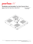
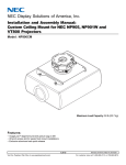
Installation and Assembly:
Wireless PRG Precision Gear Projector Mount
Model: WL-PRG-UNV-200
Features:
• ImageLockTM alignment prevents picture sag or drift
• Exclusive aluminum track quick release
Max Load Capacity: 50 lb (22.7 kg)
2300 White Oak Circle • Aurora, Il 60502 • (800) 865-2112 • Fax: (800)359-6500 • www.peerless-av.com
ISSUED: 08-24-12 SHEET #: 180-9035-2 10-30-12
NOTE: Read entire instruction sheet before you start installation and assembly.
WARNING
• Do not begin to install your Peerless product until you have read and understood the instructions
and warnings contained in this Installation Sheet. If you have any questions regarding any of the
instructions or warnings, for US customers please call Peerless customer care at
1-800-865-2112, for all international customers, please contact your local distributor.
• This product should only be installed by someone of good mechanical aptitude, has experience
with basic building construction, and fully understands these instructions.
• Make sure that the supporting surface will safely support the combined load of the equipment and
all attached hardware and components.
• Never exceed the Maximum Load Capacity. See page one.
• If mounting to wood wall studs, make sure that mounting screws are anchored into the center of
the studs. Use of an "edge to edge" stud finder is highly recommended.
• Always use an assistant or mechanical lifting equipment to safely lift and position equipment.
• Tighten screws firmly, but do not overtighten. Overtightening can damage the items, greatly
reducing their holding power.
• This product is intended for indoor use only. Use of this product outdoors could lead to product
failure and personal injury.
• This product was designed to be installed on the following wall construction only;
WALL CONSTRUCTION
• Wood Stud
• Wood Beam
• Solid Concrete
• Brick
• Other or unsure?
HARDWARE REQUIRED
Included
Included
Included
Contact Qualified Professional
Contact Qualified Professional
Tools Needed for Assembly
•
•
•
•
•
•
•
stud finder ("edge to edge" stud finder is recommended)
phillips screwdriver
drill
5/16" bit for solid concrete surface
5/32" bit for wood studs
open end wrench
level
Table of Contents
Parts List................................................................................................................................................ 3
Projector Mount Assembly Installation................................................................................................5-9
Attaching Adapter Plate to Projector.................................................................................................... 10
Accessories ................................................................................................................................... 18, 19
2 of 24
ISSUED: 08-24-12 SHEET #: 180-9035-3 11-08-12
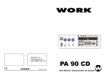
Before you start check the parts list to insure all of the parts shown are included.
Parts List
Description
projector mount assembly
adapter plate
concrete anchor
#14 x 2-1/2" phillips hex head wood screw
#10-32 x 1/4" socket pin screw
1/4" flat washer
#6 flat washer x 1/2" OD
2 mm security allen wrench
4 mm security allen wrench
M3 x 8 mm serrated washer head socket pin screw
M4 x 10 mm serrated washer head socket pin screw
M5 x 10 mm serrated washer head socket pin screw
M6 x 10 mm serrated washer head socket pin screw
wireless mount
wireless receiver
10-32 x 1/4 serrated washer head socket pin screw
A
B
C
D
E
F
G
H
I
J
K
L
M
N
O
P
Qty.
1
1
2
2
1
2
4
2
2
4
4
4
4
1
1
1
WL-PRG-UNV-200
Part #
054-1171
055-1938
590-0320
5S1-015-C03
520-1196
540-1078
540-1025
560-1097
560-9646
510-1004
510-1060
510-1126
510-1066
120-1211
180-1203
510-1056
NOTE: Actual parts may appear slightly different than illustrated.
A
B
D
C
E
J
G
F
K
L
I
H
M
N
O
P
3 of 24
ISSUED: 08-24-12 SHEET #: 180-9035-3 11-08-12
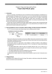
Additional Wireless Components
wireless transmitter (1)
(180-1202)
vga to rca adapter (1)
(180-1006)
plastic stand (1)
(180-1205)
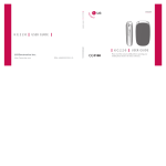
User Manual and Installation Guide
Pro Wireless Multimedia Kit
Models:
HDS200
HDS200-2
HDS200-3
HDS200-4
®
READY
ISSUED: 06-12-12 SHEET #: 180-9023-1
remote (1)
(180-1207)
instruction sheet (1)
(180-9023)
ir flasher (1)
(180-1009)
Quic
k StartGuide
PRO WIRELESS MULTIMEDIA
T KI
®
READY
2
Minute
s
M odel No.
HDS200 (-2,-3, -4
)
tu on the display device the HD Flow
Multimedia
Pro Wireless
tuni
s will be goingghthrou
the r
sta
tup process. This
process may
Step 7 Whilerning
take up tto
wo minutes to complete. The
r/Link
Powe
indicator
gh
ts on
li the
Transmi
tter and the Re
. Flashing indicates
that the tsuni
are establishing a secure
ction.conne
Wait until the
ction
conne
is success
fully established, indicatedwer
by
/Link
the indicator
Po
li
ght becoming solid.
W hat’sin the B
ox
1 xTransmi
tter
1 x Ex
IRtender
1 x Receiver
1 x Component Adaptor
2 x Stand
2 x Power Adapter
1 x Remote Control1 x QuickrtSta
Guide
1 x Fla
IR sher
1 x Users Manual
Power/
Source
Select
ion Butto
n
Insta
llatio
n and Setup
TipThe IR window
may be easier to
locate with ct
a dire
light shining on
sections of the
front panel of the
component device.
Step 8Sele
ct the output thatctsconne
the
Receiver to the display using
the Powe
r/Source Selection
ttonBuor the provided remote control.
The output indicator
ght will
li become solid and
Flow
the
logo
HD will
appear on the display device.
Step 9Turn on the desired source device that
ed tois connect
theTransmi
tter.
works well.
Step 1 Conne
ct the
Transmit
ter to source
the
devices
(Bluray™ Discplaye
r, set top
x,gaming
bo
con
sole, etc.).
Step 2 Conne
ct the provided
Fla
sIR
her to the
R-OUTI port on the
Transmi
tter.
Find the location of the IR your
window
source
on device and adhere the
IR asher
Fl
eye ctly
dire over the IR window on your source device.
NOTE: One IR
Flasher eye
s to
be
i used for one component device.
Power/
Source
Select
ion Butto
n
ct the desired source
device
or input on
Transmi
the tter
Step 10 Sele
using the Powe
r/Source Sele
ction t
Bu
ton on the remote control.
Step 11Play the source device content and enjoy up to Full HD
wireless ente
rtainmentxperience.
e
Troubleshootingips
T
• Check the media source resolution. The display device must be
Transmi
tter an
d/or Receiver Indicator
ts are
Ligh
ll aBlinking:
to suppo
rt the resolution of the media source that is being str
• The HDFlow Pro t
uni
s are establishingction.
a conne
It can take
Utilizing the INFO
tton bu
will allow you to see the resolution data
up to
two minutes for the HD Flow
ts Pro
to establish
uni
a complete
suppo
. If the
display device rsuppo
ts theghes
hi t
connection. fIf
tertwo
a minutes have passed and the units have not the display devicerts
resolution of 720p but the source t
device
ting 1080p
is outpu
content,
established a ction,
conne unplug
e power
th
cable, wait 30 seconds
the content needs to be down-scale
d to theaximum
m
resolution of the
and reconne
ct the power supply to
ts.the uni
display device, as
ine this
720p.c
TipRepeatSteps
Steps
3-11 to conne
ct
ect
more thanneone
Receiver tunit
(HDS200-2,
HDS200-3,
HDS200-4).
di display
l d vi
ice(T
( V, monito
i r, proje
j ctor, et
)
Step 3Connect hthe
de
c.)
to the Rece
ive
r.
the
tender
IR by plug
ging in the provided
Extender
IR in to
Step 4 Install Ex
the R-IN
I
po
rt on the Receiver and
ng adheri
the other end of
Extender
the IR
to a rve
ticalrf
a
su
ce near the output device. Ensure
Extender
that the
is in
IR
a line ght
of si
to the remote control l
that
s your
contro
source devices.
receivers
three and four do not come
Extende
withr. anAdditional
IR
tenders
IR Ex
NOTE: For Multicast models,two,
(HDS-IRE) can be purchased separately;v.com
visit
for
peerless-a
more information.
Step 6Turn on your display(TV,
device
monito
r, proje
ctor, etc
.).
Step 5 Powe
r-up the Flow
HD
Pro Devices.
tter
and the Receiver to nearby
1. Plug in the power adapter
Transmi
for
the
available powerts
outle
.
2.Plug in the power
adapterend to
he Transmi
t
tter and then to ther. Receive
3. The t
uni
s will automatically
rnon. tu
The average r-powe
on/sync time
is approximately
two minutes.
© 2012 Peerless Industries,
c. Peerless-AV™
In
is a trademark of Peerless
Allght
Industries,
ri
s rese
rved.
Inc.
12v power adapter (1)
(180-1004)
hdmi cable (2)
(600-0234)
IR extender (1)
(180-0029)
Transmi
tter or
Receiver Power Indicator Light
F:
is OF
• Check and veri
fy thepower supply conne
ction.
Receiver Output Indicator
lin
ksLight
:
B
• Make sure that your display
vice,source
de de
vic
e and the Fl
HD
ow Prounits
are all
urned
t ON and the
Receiver is properly connected to ithe
ce. output
Transmi
tter Input Indicator
lin
ks
Light
:
B
• Veri
fy that the Receiver is set to the appropriate
rt.
output po
• Make sure that your source rdevice
ned ON is
andtuthe cable
• Check the resolution
tting se
of your source device. This may need to
is properly conne
cted.
changed to a resolution
rted
suppo
by the HD Flow Pro unit. Reference
• Veri
fy that Transmi
the tter is set to the appropriate
rt. input po
the Resolution
rt Cha
in theFlow
HD Pro Manual for compatibili
ty.
• Check the resolution
from your source device. This may need to
Reference your source devices’ manual
ction
for
on instru
chan
ging
be changed to a resolution
rtedsuppo
by the HD Flow Pro Wireless
the output resolution.
Multimedia Reference
Kit.
the Resolution
rt inCha
theFlow
HD Pro
e your source devices’ manual
Manual for compatibili
ty. Referenc
If the above troub
leshooting tips do not resolve the issues
ast setup,
for a uni
for instru
ction on chan
ging the output resolution.
please referenceFac
the
tory Reset ction
Se
of thelow
HDPro
F Manual.
For a
Receiver Power Indicator ks
Light
:
Blin
• Veri
fy that theFlow
HD Pro
Transmi
tter and Receiver are within
the recommended range
131offeet.
Physical obstru
ctions such
as
theTransmi
tter and Receiver may
decre
ase the stren
gth of the connec
tion gnal
si and reduce the overall
transmission range.
If a conne
ction has been lished
estab and thelo
HD
w logo
F can be seen
on the display device, but content is not playing:
• Make sure that the
/output
input cables are properly
cted.conne
• Veri
fy that the
Transmi
tter is set to the appropriate
rt. input po
800-856-2112 ffor
urther instruction.
Warning Do not place the
Flow
HD
Pro uni
ts near other
vices
de tha
t
emitexcessive amounts of heat.
Incre
ased tem
p eratures yma
cause the Flow
HD Pro
Transmi
tter
or Receiver unit function
to mal
orstop wo
r king
.
Quick ta
Srt Guide
for HDFlow Pro Wireles
s Multimedia
Kit LI
-T-090
6
install guide (1)
(LIT-0905)
3v battery (1)
(180-0008)
4 of 24
ISSUED: 08-24-12 SHEET #: 180-9035-3 11-08-12
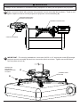
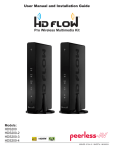
Installation to Extension Column/Ceiling Plate
1
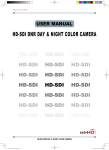
NOTE: Refer to accompanying instructions with ceiling plates (sold separately) for installing
these models to ceiling.
Screw projector mount assembly (A) onto extension column as shown in figure 1.1.
Tighten swivel stop screw against extension column, flush mount tube or reducer using 4mm
security allen wrench (I) as shown in figure 1.2.
NOTE: Swivel stop screw is used to jam against threads of extension column, flush mount tube
or reducer to prevent any excess movement of projector mount assembly (A). Do not overtighten
screw; overtightening screw will damage threads making it difficult to separate products.
Skip to step 5.
1-1/2" EXTENSION COLUMN
(SOLD SEPARATELY)
(UL LISTED EXT OR AEC SERIES)
ARROW INDICATES
FRONT OF MOUNT
A
fig. 1.1
CMJ 455
(SOLD SEPARATELY)
SWIVEL STOP SCREW
fig. 1.2
5 of 24
ISSUED: 08-24-12 SHEET #: 180-9035-3 11-08-12
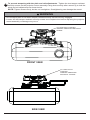
Installation to Wood Joist Ceilings
WARNING
• Installer must verify that the supporting surface will safely support the combined load of the
equipment and all attached hardware and components.
• Tighten wood screws so that wall plate is firmly attached, but do not overtighten. Overtightening
can damage the screws, greatly reducing their holding power.
• Never tighten in excess of 80 in. • lb (9 N.M.).
• Make sure that mounting screws are anchored into the center of the stud. The use of an "edge to
edge" stud finder is highly recommended.
• Hardware provided is for attachment of mount through standard thickness drywall or plaster into
wood studs. Installers are responsible to provide hardware for other types of mounting situations.
2
Place projector mount assembly (A) on ceiling as a template and mark the center of the two
mounting holes. Make sure that the mounting holes are in the center of the wood joist. Drill two
5/32" (4mm) dia. holes to a minimum depth of 2-1/2" (64mm). Attach projector mount assembly
(A) with two #14 x 2-1/2" (6mm x 64mm) wood screws (D) and two flat washers (F) as shown in
figure 2.1 or figure 2.2 depending on joist orientation.
Tighten wood screws (D) using 3/8" (10mm) socket wrench or phillips screwdriver until projector
mount assembly (A) is firmly attached.
Skip to step 5.
WOOD JOIST
ACCESS SLOT FOR
OPEN END WRENCH
ALLOWS TIGHTENING
OF WOOD SCREW (D).
fig. 2.1
ACCESS SLOT FOR
OPEN END WRENCH
ALLOWS TIGHTENING
OF WOOD SCREW (D).
WOOD JOIST
fig. 2.2
A
F
D
A
F
D
6 of 24
ISSUED: 08-24-12 SHEET #: 180-9035-3 11-08-12
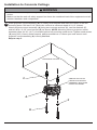
Installation to Concrete Ceilings
WARNING
• Concrete must be 2000 psi density minimum. Lighter density concrete may not hold concrete
anchor.
• Make sure that the wall will safely support four times the combined load of the equipment and all
attached hardware and components.
3
Place projector mount assembly (A) on ceiling as a template and mark the center of the two
mounting holes. Drill two 5/16" (8mm) dia. holes to a minimum depth of 2-1/2" (64mm).
Attach projector mount assembly (A) using two concrete anchors (C), two flat washers (F),
and two #14 x 2-1/2" wood screws (D) as shown. NOTE: Mounting slots on projector mount
assembly allow for 30° (±15°) of rotation before fully securing wood screw. Tighten wood screws
(D) using 3/8" (10mm) socket wrench, phillips screwdriver or 10mm open end wrench until
projector mount assembly (A) is firmly attached.
Skip to step 5.
CONCRETE CEILING
C
ARROW ON TOP OF
PROJECTOR MOUNT
ASSEMBLY INDICATES
FRONT OF MOUNT
A
F
D
7 of 24
ISSUED: 08-24-12 SHEET #: 180-9035-3 11-08-12
WARNING
• Always attach concrete expansion anchors directly to load-bearing concrete.
• Never attach concrete expansion anchors to concrete covered with plaster, drywall, or
other finishing material. If mounting to concrete surfaces covered with a finishing surface is
unavoidable, the finishing surface must be counterbored as shown below. Be sure concrete
anchors do not pull away from concrete when tightening screws. If plaster/drywall is thicker than
5/8" (16mm), custom fasteners must be supplied by installer.
• Tighten screws so that projector mount is firmly attached, but do not overtighten. Overtightening
can damage screws, greatly reducing their holding power.
• Never tighten in excess of 80 in. • lb (9 N.M.).
INCORRECT
1
A
CUTAWAY VIEW
C
Drill holes and insert anchors (C).
2
concrete
concrete
surface
A
plaster/
dry wall
CORRECT
A
concrete
C
D
Place plate (A) over anchors (C) and secure with
screws (D).
plaster/
dry wall
3
Tighten all fasteners.
8 of 24
ISSUED: 08-24-12 SHEET #: 180-9035-3 11-08-12
Installation to Threaded Rod
(Professional installation only)
4
Thread two 1/4-20 hex thin nylon-insert locknuts (not included) on two 1/4-20 threaded rods (not
included) to the desired height of projector mount assembly. Attach projector mount assembly
(A) to the two 1/4-20 threaded rods using two 1/4-20 hex thin nylon-insert locknuts as shown in
figure 4.1 or figure 4.2.
1/4-20 THREADED
ROD (NOT
INCLUDED)
1/4-20
THREADED
ROD (NOT
INCLUDED)
1/4-20 HEX THIN
NYLON-INSERT
LOCKNUT (NOT
INCLUDED)
1/4-20 HEX
THIN NYLONINSERT
LOCKNUT
(NOT
INCLUDED)
ARROW
INDICATES
FRONT OF
MOUNT
ARROW
INDICATES
FRONT OF
MOUNT
fig. 4.1
fig. 4.2
A
A
1/4-20 HEX
THIN NYLONINSERT
LOCKNUT (NOT
INCLUDED)
1/4-20 HEX THIN
NYLON-INSERT
LOCKNUT (NOT
INCLUDED)
9 of 24
ISSUED: 08-24-12 SHEET #: 180-9035-3 11-08-12
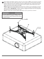
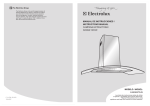
Attaching Adapter Plate to Projector
5
NOTE: The projector you are installing may differ in appearance from the sample illustrated
below.
Place projector upside down. Locate adapter plate (B) with notch facing forward as close to
projector center of gravity as possible without covering any mounting holes. Loosen channels
with 4mm security allen wrench (I), and if there are only three mounting holes remove fourth
channel. Using one channel for each mounting hole, position feet of channels over mounting
holes as shown below. IMPORTANT: If projector does not have at least three mounting holes,
do not use this adapter plate.
NOTE: Some projectors have feet which can be removed and the corresponding threaded insert
can be used for a mounting hole.
NOTE: Once channels are in position retighten fasteners.
*Notch indicates front of projector.
CHANNEL
FOOT OF
CHANNEL
MOUNTING HOLE
B
*
GENERIC PROJECTOR
10 of 24
ISSUED: 08-24-12 SHEET #: 180-9035-3 11-08-12
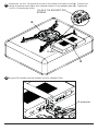
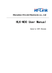
6
Attach adapter plate (B) to projector using one screw (J, K, L or M) for each channel as shown
below. Tighten all screws, while keeping the center of gravity. Be sure that adapter plate (B) is
straight. Adjust the feet of the channels to keep the adapter plate level. Tighten all screws with
4mm security allen wrench (I) while keeping the center of gravity. If M3 screws (J) are used,
tighten using 2mm security allen wrench (H).
NOTE: Projectors will require different size screws for mounting. Use a combination of screws
(J, K, L or M) and foot adjustment that will result in channels of adapter plate (B) fitting tightly
against projector. IMPORTANT: In order to properly engage the threads in the mounting holes,
the screw must be turned at least 3 full turns.
NOTE: If using screw (J), place washer (G) between screw (J) and foot of channel.
CAUTION
• It is the responsibility of the installer to ensure
that the projector is properly ventilated. Feet
of channels are used to raise the mount off the
projector surface.
J, K, L or M
B
FOOT OF
CHANNEL
11 of 24
ISSUED: 08-24-12 SHEET #: 180-9035-3 11-08-12
7
Remove 10-32 x 1/4" screw from wireless mount (N). Position wireless receiver (O) in wireless
mount. Secure in place by reinserting 10-32 x 1/4" phillips screw.
For security applications, install 10-32 x 1/4 serrated washer head socket pin screw (P) in place
of the 10-32 x 1/4" phillips screw and secure using 4mm security allen wrench (I).
N
10-32 x 1/4" phillips screw
O
10-32 x 1/4" phillips screw
or
P
12 of 24
ISSUED: 08-24-12 SHEET #: 180-9035-3 11-08-12
8
Loosen the 1/4-20 x 7/8 socket pin screw on the clamp of wireless mount (N). Position the
clamp of wireless mount (N) to your desired location on the adapter plate (B) . Tighten the
1/4-20 x 7/8 socket pin screw.
1/4-20 X 7/8 SOCKET PIN
SCREW
B
CLAMP
N
9
Plug the IR extender into the wireless receiver (labeled IR-IN).
IR extender
13 of 24
ISSUED: 08-24-12 SHEET #: 180-9035-3 11-08-12
10 that it is in the line of sight of any possible remote use.
Remove the adhesive backing from the IR extender and mount to the bottom of the projector so
11 Plug the component cable(s) from your projector (HDMI shown) into the wireless receiver.
COMPONENT CABLE
14 of 24
ISSUED: 08-24-12 SHEET #: 180-9035-3 11-08-12
WARNING
• Always use an assistant or mechanical lifting equipment to safely lift and position the projector.
connection block with projector into projector mount assembly (A) as shown.
12 Slide
tighten captive screw to secure projector to projector mount assembly (A).
Push in and
ARROW INDICATES
FRONT OF MOUNT
CONNECTION BLOCK
A
CAPTIVE SCREW
13 IMPORTANT:
For security installations, insert one #10-32 x 1/4" socket pin screw (E) through
projector mount assembly (A) and into connection block as shown. Tighten screw with 4mm
security allen wrench (I).
WIRELESS
RECEIVER
REMOVED FOR
CLARITY
A
CONNECTION
BLOCK
E
15 of 24
ISSUED: 08-24-12 SHEET #: 180-9035-3 11-08-12
Projector Alignment
14 threaded rods (refer to step four) until projector mount can be rotated.
To adjust yaw (swivel) for threaded rod mounting applications: Loosen locknuts for
Rotate mount to desired
position and retighten locknuts.
To adjust yaw (swivel) for extension column applications: Loosen screw on projector mount
assembly (A) indicated below until projector mount can be rotated. Rotate mount to desired
position and retighten screw.
To adjust pitch (forward and backward tilt): Turn knob on back of mount as shown below.
Pull knob out and turn by hand for easy adjustment or insert #2 phillips screwdriver in end of
knob and turn.
To adjust roll (side to side tilt): Turn knob on side of mount as shown below. Pull knob out and
turn by hand for easy adjustment or insert #2 phillips screwdriver in end of knob and turn.
A
ARROW INDICATES
FRONT OF MOUNT
KNOB FOR PITCH
ADJUSTMENT
KNOB FOR ROLL
ADJUSTMENT
SCREW FOR YAW
(SWIVEL) STOP
16 of 24
ISSUED: 08-24-12 SHEET #: 180-9035-3 11-08-12
15 security screws on the projector mount assembly using 4mm security allen wrench (I) to lock the
To prevent tampering with the pitch and roll adjustments: Tighten the two tamper resistant
pitch and roll adjustments as shown below.
NOTE: Tighten screws firmly, but do not overtighten. Overtightening can damage the mount.
WARNING
• Do not adjust pitch or roll while tamper resistant security screws are fully engaged.
• Loosen the two tamper resistant security screws one complete turn before adjusting the projector
mount assembly or damage may occur.
TO LOCK ROLL TIGHTEN
TAMPER RESISTANT SECURITY
SCREW
FRONT VIEW
TO LOCK PITCH
TIGHTEN
TAMPER RESISTANT
SECURITY SCREW
SIDE VIEW
17 of 24
ISSUED: 08-24-12 SHEET #: 180-9035-3 11-08-12
16 wireless receiver as shown.
Plug the end of the wireless receiver power adapter into the input port marked DC on the
Plug the other end into your power source.
17
To complete the installation of your wireless projector, please refer to the HD Flow™ User's
Manual and the HD Flow™ Install Guide included.
18 of 24
ISSUED: 08-24-12 SHEET #: 180-9035-3 11-08-12
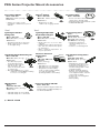
PRG Series Projector Mount Accessories
Ceiling Plates
Escutcheon Ring
Unistrut® Adapter
Truss Ceiling Adapter
MODEL: ACC 557*
MAX LOAD: 250 lbs. (113.4 kg.)
COLOR: Black
MODEL: ACC 640
MODEL: ACC 550
MAX LOAD: 250 lbs. (113.4 kg.)
COLOR: Black
• Covers hole where extension
column passes through ceiling
• Hinged ring wraps around extension column
• Included with CMJ 500
R
• Attaches to a square, round,
rectangular, or I-Beam truss up to 3" in
diameter
New!
• Designed for use with
1 5/8" x 1 5/8" 12 gauge Unistrut
New!
Lightweight Cathedral
Ceiling Plate
Lightweight Adjustable
Suspended Ceiling Kit
R
MODEL:
ACC570(S)(W)
COLOR: Black, silver or white
MAX LOAD: 150 lb (68 kg)
SHIP WEIGHT: 1.7 lb (.8 kg)
MODEL: ACC 912*
MAX LOAD: 60 lbs. (27.2 kg.)
COLOR: Black
MODEL: CMJ 500
MAX LOAD: 60 lbs. (27.2 kg.)
COLOR: White
• Designed specifically for projectors
• Allows a projector to be mounted
on an angled ceiling
• Mounts above 2’ x 4’ or 2’ x 2’ false
ceiling tile
• Includes tie wire supports, flush mount
tube, and offers two knockout panels
for outlet boxes
• Offers unlimited adjustment for
projector placement
Lightweight Suspended Ceiling Kit
MODEL: CMJ 455
MAX LOAD: 50 lbs. (22.7 kg.)
COLOR: White
Unistrut
MODELS:
CMJ 300*, CMJ 310*
MAX LOAD:
• Five different projector
mount attachment points
• Includes tie wire supports,
flush mount tube, and
offers two knockout panels
for outlet boxes
• May either replace a 2’ x 2’ false
ceiling tile or mount above an existing
2’ x 2’ or 2’ x 4’ ceiling tile
R
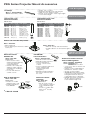
I-Beam Clamps
MODELS:
ACC 558, ACC 559
MAX LOAD: 250 lbs. (113.4 kg.)
COLOR: Black
Unistrut or Structural
Ceiling Plates
250 lbs. (113.4 kg.)
COLOR: Black
Round Ceiling Plate
Ceiling plate
• CMJ 300 is a 4" x 4" ceiling plate
• CMJ 310 is a 8" x 8" ceiling plate
• Designed for a Unistrut ceiling
(1 5/8" x 1 5/8" 12 gauge Unistrut)
or a solid structural ceiling
(mounting hardware not included)
R
• Designed for finished or
structural ceilings (wood or
concrete)
• Features a cord management
Anti-Vibration Ceiling Plates
MODELS:
ACC 840*, ACC 845*
MAX LOAD: 60 lbs. (27.2 kg.)
COLOR: Black
• ACC 840 was designed for
a structural ceiling (wood only)
• ACC 845 was designed for
a Unistrut ceiling (1 5/8" x 1 5/8"
12 gauge Unistrut)
• Reduces unwanted vibrations
that may cause internal damage
to the equipment and/or cause the
screen image to vibrate
• Features two cord management
access holes
• Patent pending
Accessory Pack for CMJ 455
MODEL: ACC 455*
R
This pack includes 4 hanger brackets and
4 hanger clamps for additional stability. For
use with model CMJ 455.
• ACC 558 clamps onto 4"-8" I-Beam
• ACC 559 clamps onto 7"-12" I-Beam
* = Not UL Listed
19 of 24
ISSUED: 08-24-12 SHEET #: 180-9035-3 11-08-12
PRG Series Projector Mount Accessories
Cord Management
• Includes, four, 2' sections
• Designed to externally route cords along the
outside of an 1/2" extension column
• Sections can be stacked to create longer lengths
or cut to desired length
Cord Wrap
MODELS: ACC 852(W)(S)*
COLOR: Black, White, or Silver
Extension Columns
Adjustable Length 1 1/2"
Extension Columns
Fixed Length 1 1/2"
Extension Columns
COLOR: Black
COLOR: Black
MODEL
EXT 006
EXT 018
EXT 101
EXT 102
EXT 103
EXT 104
EXT 105
EXT 106
EXT 107
EXT 108
EXT 109
EXT 110
Drop Length
8" (20 cm)
20" (51 cm)
14" (36 cm)
26" (66 cm)
38" (97 cm)
50" (127cm)
62" (158 cm)
74" (188 cm)
86" (219 cm)
98" (249 cm)
110" (279 cm)
122" (310 cm)
Ship Weight
2.5 lbs (1.13 kg)
5 lbs (2.27 kg)
3.5 lbs (1.59 kg)
6 lbs (2.72 kg)
9.25 lbs (4.2 kg)
12 lbs (5.44 kg)
14.75 lbs (6.69 kg)
18 lbs (8.16 kg)
20.75 lbs (9.41 kg)
23.25 lbs (10.55 kg)
26.5 lbs (12.02 kg)
29 lbs (13.15 kg)
R
MODEL
ADJ 006009
ADJ 012018
ADJ 018024
ADJ 0203
ADJ 0305
ADJ 0406
ADJ 0507
ADJ 0608
ADJ 0709
ADJ 0810
ADJ 0911
ADJ 1012
Drop Length
8"-11"
14"-20"
20"-26"
26"-38"
38"-62"
50"-74"
62"-86"
74"-98"
86"-110"
98"-122"
110"-134"
122"-146"
Ship Weight
4 lbs. (1.81 kg)
4.75 lbs. (2.15 kg)
6.25 lbs. (2.83 kg)
8 lbs. (3.63 kg)
13.5 lbs. (6.12 kg)
16.25 lbs. (7.37 kg)
18.5 lbs. (8.39 kg)
21.75 lbs. (9.87 kg)
24.5 lbs. (11.11 kg)
27 lbs. (12.25 kg)
29 lbs. (13.15 kg)
31 lbs. (14.06 kg)
R
Security Accessories
Armor LockTM Plus Security Cables
MODEL: ACC 020*
MODEL: ACC 021*
• With security lock
• For use with projectors that have a built-in
security slot
ALLIGATOR
Concrete Anchors
MODEL: ACC 050*
COLOR: Black
MODELS: ACC 203, 204
• ACC 203 contains 3 anchors
• ACC 204 contains 4 anchors
• Used for attachment to
concrete, concrete block,
or brick
• Used in conjunction with wood
screws (supplied with
projector mount and/or
ceiling plate)
• Expands in length and binds to
the contours of the hole and
the screw
• Can be used to reduce
unwanted swaying that may
occur with extension
column installations
• Includes a hose clamp, two
stabilizer column supports,
& hardware for mounting to
wood joists
• For use with extension
columns over 21"
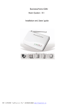
Side-To-Side Adjuster
R
Extension
column
Side to side
adjuster
• 1-1/2" access hole for internal cord
management
• Unit has 1-1/2"-11.5 NPT fitting for
attachment of extension column
• Security screws included
• ACC800: One male and one female
connection to provide internal cord
management between extension
column and mount or ceiling plate
• ACC850: Two female connectors to
join two extension columns to
create maximum length of 20’
MODEL: ACC 109*
COLOR: Black
• Can be used to join two
1-1/2" extension columns to
create a maximum length
of 20’
• Secures to columns with
Armor LockTM Security
screws
20 of 24
Extension Column Connector
with Cord Management
MODEL: ACC800, ACC850(S)
COLOR: ACC800 Black
ACC850 Black or Silver
Extension Column
Connector
MODEL: ACC 830*
COLOR: Black
* = Not UL Listed
Additional Projector
Mount Accessories
®
Extension Column
Stabilizer Kit
• Provides 4" of radial
adjustment side to side
• Includes Flush Mount
Tube, EXT 002
• With 1/4" security cable and fasteners
• Includes adhesive for non-fastener applica
tions
ACC800
ACC850
ISSUED: 08-24-12 SHEET #: 180-9035-3 11-08-12
This page intentionally left blank.
21 of 24
ISSUED: 08-24-12 SHEET #: 180-9035-3 11-08-12
This page intentionally left blank.
22 of 24
ISSUED: 08-24-12 SHEET #: 180-9035-3 11-08-12
LIMITED WARRANTY
Peerless Industries, Inc. (“Peerless-AV®”) warrants to original end-users of Peerless-AV® products that Peerless-AV® products will be
free from defects in material and workmanship, under normal use, for the periods listed below, from the date of purchase by the original
end-user. At its option, Peerless-AV® will repair or replace with new or refurbished products or parts, or refund the purchase price of any
Peerless-AV® product which fails to conform with this warranty.
In no event shall the duration of any implied warranty of merchantability or fitness for a particular purpose be longer than the
period of the applicable express warranty set forth above. Some states do not allow limitations on how long an implied warranty lasts,
so the above limitation may not apply to you.
This warranty does not cover damage caused by (a) service or repairs by the customer or a person who is not authorized for such service
or repairs by Peerless-AV®, (b) the failure to utilize proper packing when returning the product, (c) incorrect installation or the failure
to follow Peerless-AV®’s instructions or warnings when installing, using or storing the product, or (d) misuse or accident, in transit or
otherwise, including in cases of third-party actions and force majeure. This warranty also does not cover corrosion or rust resulting from
damaged, scratched or chipped paint or other surfaces.
In no event shall Peerless-AV® be liable for incidental or consequential damages or damages arising from the theft of any
product, whether or not secured by a security device which may be included with the Peerless-AV® product. Some states do not
allow the exclusion or limitation of incidental or consequential damages, so the above limitation or exclusion may not apply to you.
This warranty is in lieu of all other warranties, express or implied, and is the sole remedy with respect to product defects. No dealer,
distributor, installer or other person is authorized to modify or extend this Limited Warranty or impose any obligation on Peerless-AV® in
connection with the sale of any Peerless-AV® product.
This warranty gives specific legal rights, and you may also have other rights which vary from state to state.
Product
Warranty Period
Mounts
5 years
Furniture
1 year
Cables
25 years
Cleaning Products
1 year
Electronic Products and components
1 year
23 of 24
ISSUED: 08-24-12 SHEET #: 180-9035-3 11-08-12
Peerless-AV
2300 White Oak Circle
Aurora, IL 60502
Email: tech@peerlessmounts.com
Ph: (800) 865-2112
Fax: (800) 359-6500
www.peerless-av.com
© 2012, Peerless Industries, Inc.