1
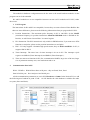
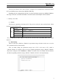
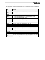
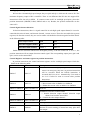
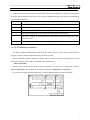
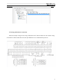
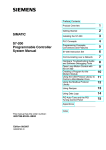
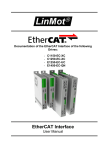
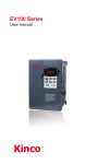
Kinco-K5 Series Updated Version of K3 Brief description of Kinco-K5 Kinco-K5 PLC is upgraded of K3 series,it is almost the same as K3 in appearance and programming. We improve the performance in both hardware and software in K5. You can use Kinco Builder V1.5.0.0 to program K5 PLC This document shows some notes and tips when you use K5 PLC. Please check the details of programming in the help file of Kinco builder. And we will release the full version of K5 user manual later. 1. K5 Modules K5 has the same name rules as K3, but modules of K5 and K3 are not compatible.Customer can not use K3 modules on K5 CPU, either the reverse. K5 has higer performance and more functions compared with K3. Please check the details of the difference between K3 and K5. IO RS232 RS485 Max RTC K5 Modules 1 K304 -- --- DI*8,DO*6 1 -- -- 1 -- 4 K504EX 1 1 2 K306 1 -- 4 K306EX DI*14,DO*10 1 1 15 K506 1 2 6 1 1 15 1 2 6 K506EA DI*14,DO*10, 1 2 6 K504 K304EX K308 DI*8,DO*6 DI*24,DO*16 K508 1. 10 times faster than K3 2. Strengen other detais yes yes yes AI*4,AO*2 1.10 times faster than K3 2. Strengen other detais 3.The max pulse output 200KHz 4. Support canopen communication via K541 module. yes Change K3 to K5 If customer uses K3 PLC program, but wants to change the hardware to K5 PLC. The following issues should be noted: Hardware configuration In new version KincoBuilder, the K5 is already in CPU list. Open the old PLC program, change the cpu type from K3 CPU to K5 CPU, K3 extension modules to K5 extension , then the program has been changed to K5 program , customer also can use K5 function. 1 Kinco-K5 Series Updated Version of K3 Note: The modules in hardware configuration must be the same as the actual hardware modules. Or the program can not be downloaded K3 and K5 modules are re not compatible.Customer can not use K3 modules on K5 CPU, either the reverse. PLC Program The instructions for K3 and K5 are comptiable, because they use same software: Kinco Builder. But there are some differences, please note the following information when you program the K5 PLC. 1) Position Instructions:The maximum pulse frequency in K5 is 200 KHz. So the MAXF (maximum frequency) in position instructions should be DWORD which is WORD in K3. Besides, we add “Reset Current Value” in control register. 2) PLS Instruction:The PLC instruction is only aviable in PWM function, if you want to use PTO function to send pulse, please use the position instructions to send pulse. 3) HSC:K5 only supports 2 channels high speed counter, they are HSC0 and HSC1. In K3, it supports HSC0~HSC5. 4) Timer Interrupt:The timer base of timer interrupt is 0.1ms in K5. The interrupte cylcle registers are SMD12 (Timer Interrupt 0) and SMD16 (Timer Interrupt 1). 5) There are some new functions in K5, like, communication PORT2, larger size of M area, larger size of permanent memory area, new instructions and so on. 2 Communication Port in K5 K506、K506EA、K508 all have three serial ports,they are Port0, Port1, Port2. Port0 is RS232 port,Port1 and port 2 are RS485 pors. All the communication parameters are set in PLC Hardware>>Comm. In the Port0 of K5, we add the following new baudrate in port0: 57.6K、115.2K. Besides the 1200 baudrate is added to the other two ports (Port1 and Port2). 2 Kinco-K5 Series Updated Version of K3 Communication Instructions The new port (Port2) is the same as Port1, it supports free communication instructions (XMT, RCV) and Modbus master instructions (MBUSR, MBUSW). Regarding the free communication of Port2, its control and status registers are SMB286~SMB294. The usage is the same as PORT0 and PORT1. Check the details in the Helpfile of Kinco Builder. 1. Memory Area of K5 a. M Area The M area is expanded to 1024 bytes in K5. They can be visit by bit, byte,word and dword. Check the detaisl in the following table M Length 1024 bytes Bit Address %M0.0 --- %M1023.7 Byte Address %MB0 --- %MB1023 Word Address %MW0 --- %MW1022 Dword Address %MD0 --- %MD1020 The corresponding modbus address of M area are 320~8511.The 320 means M0.0, 8511 means M1023.7 b. Data Backup There are 448 bytes (VB3648---VB4095) for permanent storage; the data in this area is saved in PLC permanent memory automatically. Note: In defaut setting, the permanent storage area of K5 is the same as K3, which is VB3648--VB3902. If customer wants to use the expanded permanent storage (VB3903--VB4095), they need to configure in PLC Hardware>> Others. If customer does not configure this in hardware, the data in expanded permanent storage (VB3903--VB4095) will not be stored permanently. 3 Kinco-K5 Series Updated Version of K3 c. New functions in SM area We add some new system registers and new functions in system registers. Check the the following table for details: SM Function SMB0 SM0.2 Read Only. If the reten data in RAM is lost, this bit is set to 1 in the first scan of CPU, then it is reset to 0 SMB2 SM2.0 SM2.1 Read&Write, its value depends how CPU work if fatal error happens. 0:If fatal error happens, PLC runs in independent safe sub system. 1:If fatal error happens, reset PLC directly. Read&Write, Set the working mode of the AI and AO on CPU itself. 0:Set AI/AO chnnels in normal working mode. 1:Set AI/AO chnnels in adjusting mode. SMB6 SMB6 Read Only, store the latest scan time of PLC, unit:ms. SMW10 SMW10 Read Only, store the voltage value of back-up battery, unit:0.01V。 SMD12,SMD16 SMD12 Read&Write.Set the cycle of Timer Interrupt 0, unit: 0.1ms SMD16 Read&Write.Set the cycle of Timer Interrupt 1, unit: 0.1ms The cycle of Timer Interrupt 0 and 1 are set in SMW22 and SWM24 in K3, these two are not used in K5. SMB286-SMB294 Read&Write. Cntrol and status registers in free communication of Port2, SMB286-SMB2 The detail functions are the similar as port0 and port1 in K3, please refere 94 to the corresponding pages in help file of Kinco Builder 4 Kinco-K5 Series Updated Version of K3 2. I/O ports in K5 High Speed Input K5 provide 2 high speed counters: HSC0 and HSC1. The counting value is stored in HC0 and HC1.The maximum counting frequencies are: single phase: 60 KHz, double phase (A/B phase included): 20 KHz. The software programming of HSC0 and HSC1 in K5 is the same as K3. Please refer to the Help file of Kinco Builder for the information. There is some differences in the hardware inputs, check the following table for details. HSC 0 Mode 0 Description 1 Single-phase up/down counter with internal direction control 2 Direction Control:SM37.3 3 Single-phase up/down counter with external direction control 4 I0.1 I0.0 Clock Reset Reset I0.5 Start Direction Clock Reset Clock 6 Two-phase counter with up/down clock inputs (Down) 9 A/B phase quadrature counter Clock (A) Direction Clock(Up) Clock (B) HSC1 Mode Description I0.4 0 1 Single-phase up/down counter with internal direction control Reset 2 Direction Control:SM47.3 Reset I0.6 I0.3 Clock Start 3 4 I0.2 Direction Single-phase up/down counter with external direction control 5 Clock Reset Reset Start Direction Direction 6 7 Two-phase counter up/down clock inputs with 8 Reset Reset Clock Clock (Down) (Up) Clock(A) Clock(B) Start 9 10 11 A/B phase quadrature counter Reset Reset Start 5 Kinco-K5 Series Updated Version of K3 High Speed Output K5 Provides 2 channels high speed output, they are Q0.0 and Q0.1, which are the same as K3. The maximum frequency output of K5 is 200 KHz. There is one difference that K5 does not support PLS instruction in PTO, but only in PWM. If customer wants use K5 to send high speed pulse, please the position instructions (PHOME, PABS, PREAL and so on). Besides, the position instructions are the same as K3. Control Signal of motor direction In Position instructions, there is a signal control bit in each high speed output channel, it is used to control the direction of motor, and 0 means forward, 1 means reverse. There also are enable bits (system registers) for direction control, they are used to enable or disbable the direction signal.Check the details in the following table: Pulse Output Channel Q0.0 Q0.1 Direction Oupput Channel Q0.2 Q0.3 Direction Enable Control SM201.3 SM231.3 Enable bits for direction control have the highest priority, if the the enable bits is set to 1, the position instruction will not output direction control signal. The corresponding output ports (Q0.2 and Q0.3) can be used as normal DO. Control Registers and status registers in position instructions In position instructions, the control and status registers are for each high speed output. Check the details in the following table: Q0.0 Q0.1 Description Read&Write. Bit of emergency stop, if this bit is 1, the motor is in emergency stop state, no position instructions will be executed. When the PSTOP instruction is SM201.7 SM231.7 executed, this bit is set to 1 automatically. User needs to set it to 0 before he want to execute other position instructions. Read&Write.Reset the current value or not SM201.6 SM231.6 1 --- Reset current value in SMD212 or SMD242 0 --- Holdon the current value in SMD212 or SMD242 SM201.5~SM201.4 SM231.4~SM231.5 Reserved SM201.3 SM231.3 Read&Write.Direction Control Enable 1 --- Disable direction output channel, direction ouput channel can beusedas normal DO. 0 --- Enable direction output channel。 SM201.0~SM201.2 SM231.0~SM231.2 Reserved Q0.0 Q0.1 SMD212 SMD242 Description Read Only, the current value (increase in forward rotating, decrease in reverse rotating), it means how many pulse have been output. 6 Kinco-K5 Series Updated Version of K3 In K5 PLC, the MAXF parameters are DWORD, which are WORD in K3. When the error happens in position instructions, the error codes will be output to ERRID parameter, the detail error information are in the following table: Error Code Description 0 No error 1 The initial pulse cycle exceeds the time of each segment 2 The initial speed (MINF) exceeds the highest pulse speed (400KHz). 3 The initial speed(MINF) is lower than the lowest pulse speed(125Hz) 4 The pulse number in acceleration and deceleration progress exceeds the total number of pulse. 5 The initial speed (MINF) exceeds the highest speed(MAXF) 5 CANopen Communication Function We add a Canopen communication module in K5, which is K541. All K5 PLC except K504 can support CANopen master communication by one K541 module. There is terminal resistor (120ohms) in K541; user can add it to network according to the actual application. Besides, K541 supports standard 10K~1M baudrate. How to use K541 Add the K541 at the end of all the extension modules. User needs not config K541 in Kinco Builder (Hardware). Just onfigure the CANopen parameters in Hardware>>CANopen User can use CANopen master fcntion and CAN free communication function in program. 7 Kinco-K5 Series Updated Version of K3 K5 wiring and hardware connection Check the sample wiring for the wiring of K506EA-30AT. Other modules have the similar wiring in normal I/O. Other models have the same pin definition in two communication ports too. 8