1
Cover - 233.qxp
11/11/2009
11:29 AM
Page 1
CIRCUIT CELLAR
Embedded Networking with the iMCU W7100, p. 14 • Extend the I2C Bus, p. 64
www.circuitcellar.com
THE
MAGAZINE
FOR
COMPUTER
A P P L I C AT I O N S
#233 December 2009
PROGRAMMABLE LOGIC
Retrocomputing with
Programmable Logic
Microprogramming
with FPGAs
Addressing Memory
Failures
Digital Modulation
Theory
6LoWPAN Explained
$5.95 U.S. ($6.95 Canada)
C2.qxp
11/2/2009
4:46 PM
Page 1
SSL Encrypted
SERIAL TO ETHERNET SOLUTIONS
Instantly network-enable
any serial device
Works out of the box no programming is required
Device P/N: SB70LC-100CR
Kit P/N: NNDK-SB70LC-KIT
$47
Qty. 1000
Customize to suit any application
with low-cost development kit
SB70LC
256-bit encryption protects data
from unauthorized monitoring
2-port serial-to-Ethernet server
Features:
10/100 Ethernet
TCP/UDP/SSH/SSL modes
DHCP/Static IP Support
Data rates up to 921.6kbps
Web-based configuration
Device P/N: SB700-EX-100CR
Kit P/N: NNDK-SB700EX-KIT
SB700EX
2-port serial-to-Ethernet server
with RS-232 & RS-485/422 support
$129
Qty. 1000
Need a custom solution?
NetBurner Serial to Ethernet
Development Kits are available to
customize any aspect of operation
including web pages, data filtering, or
custom network applications. All kits
include platform hardware, ANSI C/C++
compiler, TCP/IP stack, web server, email protocols, RTOS, flash file system,
Eclipse IDE, debugger, cables and power
supply. The NetBurner Security Suite
option includes SSH v1 & v2 support.
Device P/N: CB34-EX-100IR
Kit P/N: NNDK-CB34EX-KIT
$149
Qty. 1000
CB34EX
industrial temperature grade
2-port serial-to-Ethernet server
with RS-232 & RS-485/422 support
and terminal block connector
Information and Sales | sales@netburner.com
Web | www.netburner.com
Telephone | 1-800-695-6828
9.qxp
8/7/2008
11:04 AM
Page 1
2-3.qxp
11/2/2009
3:52 PM
Page 2
2-3.qxp
11/2/2009
3:52 PM
Page 3
T
ASK
MANAGER
Looking Back While Moving Forward
December 2009 – Issue 233
H
4
ere we are at the end of 2009. And now begins the transitional period of time when you start planning future designs
while taking stock of your past projects. To help you through
this exciting yet overwhelming time of year, we purposely put
together an issue that includes articles by designers who excel
at forging ahead with new projects by implementing the parts
they’ve acquired and the lessons they’ve learned.
The first article in this vein is “Retrocomputing on an
FPGA” by Stephen A. Edwards (p. 24). In it he describes how to
reconstruct an old Apple II computer with programmable logic.
This is an excellent example of how to use modern development
techniques to combine old and new parts in an interesting
design.
Stephen isn’t the only Circuit Cellar writer who has been
thinking about the Apple II during the last few months. In
“Digital Modulations Demystified,” columnist Robert Lacoste
reminisces about the day he connected his first 300-bps modem
to his Apple II (p. 54). He considers the differences between old
and new data transmission speeds and then explains the complicated theory and mathematics associated with the sometimes mystifying subject of digital modulations. With this information, you’ll be a step ahead of the game when you start your
next project that requires data transmission, which is probably
your very next one.
In other retro-design-related news, one of Ed Nisley’s friends
recently discovered that “memories are not forever” when he
tried to start up a Tektronix 492 spectrum analyzer. Guess what
happened. Failure. Fortunately, Ed came to the rescue with
some digital logic and firmware. The details begin on page 44.
And what would a discussion of old and new technology be
without touching on the topic of the I2C bus? Turn to page 64
where Jeff Bachiochi explains how to extend and isolate the I2C
bus. If you have a robotics design on tap, you may find Jeff’s contemporary take on this ’80s-era concept to be extremely helpful.
Don’t worry, we also have content for those of you looking for
articles on technologies and projects that aren’t so focused on
the past-present connection. First, check out Thomas Mitchell’s
article, “Building Microprogrammed Machines with FPGAs” (p.
36). He details an interesting alternative to hardwired finite
state machines.
Next, jump to page 70, where Tom Cantrell presents exciting
new technology that’s sure to get you thinking about possible
wireless IP designs, from small wireless embedded apps to large
’Net-connected systems. As you’ll see, the Internet doesn’t have
to be everywhere, but it can be if that’s what you want.
Finally, remember that the 2010 WIZnet iMCU Design
Contest is well underway. Dave Tweed’s article “iMCU
W7100” will help you started your design (p. 14). Be sure to
enter your project by June 30, 2010. Good luck!
cj@circuitcellar.com
CIRCUIT CELLAR
®
THE MAGAZINE FOR COMPUTER APPLICATIONS
FOUNDER/EDITORIAL DIRECTOR
Steve Ciarcia
CHIEF FINANCIAL OFFICER
Jeannette Ciarcia
MANAGING EDITOR
C. J. Abate
MEDIA CONSULTANT
Dan Rodrigues
WEST COAST EDITOR
Tom Cantrell
CUSTOMER SERVICE
Debbie Lavoie
CONTRIBUTING EDITORS
Jeff Bachiochi
Robert Lacoste
George Martin
Ed Nisley
CONTROLLER
Jeff Yanco
ART DIRECTOR
KC Prescott
GRAPHIC DESIGNERS
Grace Chen
Carey Penney
NEW PRODUCTS EDITOR
John Gorsky
PROJECT EDITORS
Gary Bodley
Ken Davidson
David Tweed
STAFF ENGINEER
John Gorsky
ADVERTISING
860.875.2199 • Fax: 860.871.0411 • www.circuitcellar.com/advertise
PUBLISHER
Sean Donnelly
Direct: 860.872.3064, Cell: 860.930.4326, E-mail: sean@circuitcellar.com
ADVERTISING REPRESENTATIVE
Shannon Barraclough
Direct: 860.872.3064, E-mail: shannon@circuitcellar.com
ADVERTISING COORDINATOR
Valerie Luster
E-mail: val.luster@circuitcellar.com
Cover photography by Chris Rakoczy—Rakoczy Photography
www.rakoczyphoto.com
PRINTED IN THE UNITED STATES
CONTACTS
SUBSCRIPTIONS
Information: www.circuitcellar.com/subscribe, E-mail: subscribe@circuitcellar.com
Subscribe: 800.269.6301, www.circuitcellar.com/subscribe, Circuit Cellar Subscriptions, P.O. Box 5650,
Hanover, NH 03755-5650
Address Changes/Problems: E-mail: subscribe@circuitcellar.com
GENERAL INFORMATION
860.875.2199, Fax: 860.871.0411, E-mail: info@circuitcellar.com
Editorial Office: Editor, Circuit Cellar, 4 Park St., Vernon, CT 06066, E-mail: editor@circuitcellar.com
New Products: New Products, Circuit Cellar, 4 Park St., Vernon, CT 06066, E-mail: newproducts@circuitcellar.com
AUTHORIZED REPRINTS INFORMATION
860.875.2199, E-mail: reprints@circuitcellar.com
AUTHORS
Authors’ e-mail addresses (when available) are included at the end of each article.
CIRCUIT CELLAR®, THE MAGAZINE FOR COMPUTER APPLICATIONS (ISSN 1528-0608) is published monthly by Circuit Cellar
Incorporated, 4 Park Street, Vernon, CT 06066. Periodical rates paid at Vernon, CT and additional offices. One-year (12 issues)
subscription rate USA and possessions $29.95, Canada/Mexico $34.95, all other countries $49.95.Two-year (24 issues) subscription rate USA and possessions $49.95, Canada/Mexico $59.95, all other countries $85. All subscription orders payable in
U.S. funds only via Visa, MasterCard, international postal money order, or check drawn on U.S. bank. Direct subscription orders
and subscription-related questions to Circuit Cellar Subscriptions, P.O. Box 5650, Hanover, NH 03755-5650 or call
800.269.6301.
Postmaster: Send address changes to Circuit Cellar, Circulation Dept., P.O. Box 5650, Hanover, NH 03755-5650.
Circuit Cellar® makes no warranties and assumes no responsibility or liability of any kind for errors in these programs or schematics or for the
consequences of any such errors. Furthermore, because of possible variation in the quality and condition of materials and workmanship of reader-assembled projects, Circuit Cellar® disclaims any responsibility for the safe and proper function of reader-assembled projects based upon or
from plans, descriptions, or information published by Circuit Cellar®.
The information provided by Circuit Cellar® is for educational purposes. Circuit Cellar® makes no claims or warrants that readers have a right to
build things based upon these ideas under patent or other relevant intellectual property law in their jurisdiction, or that readers have a right to
construct or operate any of the devices described herein under the relevant patent or other intellectual property law of the reader’s jurisdiction.
The reader assumes any risk of infringement liability for constructing or operating such devices.
Entire contents copyright © 2009 by Circuit Cellar, Incorporated. All rights reserved. Circuit Cellar is a registered trademark of Circuit Cellar, Inc.
Reproduction of this publication in whole or in part without written consent from Circuit Cellar Inc. is prohibited.
CIRCUIT CELLAR®
•
www.circuitcellar.com
5.qxp
11/2/2009
4:38 PM
Page 1
The Newest
Embedded Technologies
New Products from:
MiniCore™ RCM5600W Wi-Fi
Module
www.mouser.com/rabbit_
rcm5600w
MRF24J40MB 2.4 GHz RF
Transceiver Module
www.mouser.com/
microchipmrf24j40mb
TM
Joule-Thief™ Module
www.mouser.com/
adaptivenergy_joule-thief
The ONLY New Catalog Every 90 Days
Experience Mouser’s time-to-market
advantage with no minimums and same-day
shipping of the newest products from more
than 390 leading suppliers.
Beagle Board
www.mouser.com/beagleboard
The Newest Products
For Your Newest Designs
www.mouser.com
Over A Million Products Online
Mouser_CircuitCellar_12-1.indd
1
(800) 346-6873
10/15/09
10:31:42 AM
INSIDE ISSUE
233
December 2009
14
24
36
iMCU W7100
Embedded Networking Made SImple
Dave Tweed
2010 WIZnet iMCU Design Contest Primer
•
BONUS CONTENT
The Evolution of Rabbits — Five
Generations of Rabbit Microrocessors
Programmable Logic
p. 14, Get Started
with the W7100
Retrocomputing on an FPGA
Reconstruct an ’80s-Era Home
Computer with Programmable Logic
Stephen A. Edwards
Building Microprogrammed Machines
with FPGAs
Thomas Mitchell
p. 36, An Intro to
Microprogramming
December 2009 – Issue 233
p. 44, Digital
Reconstruction
6
44
ABOVE THE GROUND PLANE
Memories Are Not Forever
Ed Nisely
54
THE DARKER SIDE
Digital Modulations Demystified
Robert Lacoste
64
FROM THE BENCH
Extend and Isolate the I2C Bus
Jeff Bachiochi
70
SILICON UPDATE
IP Unplugged
Tom Cantrell
TASK MANAGER
Looking Back While Moving Forward
C. J. Abate
4
NEW PRODUCT NEWS
edited by John Gorsky
8
CROSSWORD
74
79
INDEX OF ADVERTISERS
January Preview
PRIORITY INTERRUPT
Home Automation: Everything and Nothing
Steve Ciarcia
CIRCUIT CELLAR®
•
80
www.circuitcellar.com
/11/
Hammer Down Your Power Consumption with picoPower™!
THE Performance Choice of Lowest-Power
Microcontrollers
Performance and power consumption have always been key elements in the development of AVR ® microcontrollers. Today’s
increasing use of battery and signal line powered applications makes power consumption criteria more important than ever.
To meet the tough requirements of modern microcontrollers, Atmel® has combined more than ten years of low power research and
development into picoPower technology.
picoPower enables tinyAVR®, megaAVR® and XMEGA™ microcontrollers to achieve the industry’s lowest power consumption. Why be satisfied with
microamps when you can have nanoamps? With Atmel MCUs today’s embedded designers get systems using a mere 650 nA running a real-time
clock (RTC) and only 100 nA in sleep mode. Combined with several other innovative techniques, picoPower microcontrollers help you reduce your
applications power consumption without compromising system performance!
Visit our website to learn how picoPower can help you hammer down the power consumption of your next designs. PLUS, get a chance to apply
for a free AVR design kit!
http://www.atmel.com/picopower/
Everywhere You Are®
© 2008 Atmel Corporation. All rights reserved. Atmel®, logo and Everywhere You Are® are registered trademarks of Atmel Corporation or its subsidiaries.
Other terms and product names may be trademarks of others.
picoPower 2008ad indd 1
8/8/2008 8:35:17 AM
npn233.qxp
11/12/2009
12:58 PM
Page 8
USB-POWERED MULTI-PORT SERIAL MODULES
Now available are multi-port variants of the USB-powered USBCOM-PLUS family of communication modules. These new modules
are available in RS-232 (EIA-232), RS-422 (EIA-422), or RS-485
(EIA-485) versions. The USB-COM232 modules (USB-COM232PLUS2 and USB-COM232-PLUS4) provide either dual- or quad-port
options. The USB-COM422 and USB-COM485 modules (USBCOM422-PLUS2 and USB-COM485-PLUS2) provide dual-port capability for the RS-422 differential and RS-485 multipoint differential
interfaces. Singleport versions of these interface modules (USBCOM422-PLUS1 and USB-COM4285-PLUS1) are also available.
All multi-port modules feature a USB 2.0 high-speed (480-Mbps)
interface and are powered from the USB port, saving the need for an
additional external power adapter and associated costs. PCB-mounted LEDs indicate USB enumeration, RxD and TxD signals. The complete USB protocol and all level shifting are handled by the modules
without the need for any application software modifications. In
addition, royalty-free WHQL-approved drivers are available for all
popular operating system platforms, further aiding installation and
deployment.
The whole range of modules can operate from
–40° to 85°C and are CE/FCC approved.
The modules range in price from
$19 to $60 for single-unit
orders.
Future Technology
Devices International Ltd.
www.ftdichip.com
INEXPENSIVE LINUX CONTROLLER IN
RUGGED ENCLOSURE
The OmniEP controller provides users with a rich array of
I/O devices, seamlessly supported by a preinstalled Linux
2.6 kernel. The controller comes furnished with 10/100 Ethernet, two serial
ports, batterybacked clock/calendar, USB, digital
I/Os, and stereo
audio outputs.
Optional features
include a 2 × 16
character LCD, a
push button front
panel, and rugged
aluminum enclosure. The 200-MHz
ARM9 processor
handles complex
multitasking operations efficiently. On-board memory
includes 16 MB of flash memory organized as an Ext2
filesystem and 32 MB of SDRAM. The Linux operating system also includes over 150 standard Linux/Unix system utilities, including ftp, tftp, telnet, and vi. Also included in the
development kit is a bootable Ubuntu CD-ROM preconfigured with development tools to support the OmniEP.
The board-only version OmniEP is $129 (quantity 100).
Development kits with an LCD, push button front panel, and
enclosure start at $299.
JK microsystems
www.jkmicro.com
LCD EVALUATOR PROGRAM
December 2009 – Issue 233
A new LCD Evaluator Program makes the evaluation of displays used in embedded products easier than ever. Amulet built
plug-and-play evaluator kits for popular display models from a number of leading LCD manufacturers. Designers can purchase
the kits in conjunction with a specific display through participating distributors.
The evaluator kits—powered by the GEM Graphical OS chip for color displays—assists designers through all GUI design
stages, including LCD evaluation, GUI design, and implementation. It includes a controller board featuring the GEM Graphical
OS Chip, an integrated evaluation board optimized for a specific display, a power supply, a USB cable, a stylus, and a 30-day
trial license of GEMstudio, which is Amulet’s new GUI design tool. Together with the LCD, the kit includes all of the hardware
and software required to turn an LCD into a user interface.
Until now, it has been a challenge for LCD vendors and distributors to support their customers’ needs to move quickly
through evaluation, prototyping, and production. Designers can simply connect their display with the controller board in the kit,
power it on, and the display is up and running. Using GEMstudio, the designer can easily create a GUI for an embedded
application. Designs are directly portable to production with no
additional coding required for the user interface.
LCD Evaluator Kits will start shipping through select distributors for $199 each. For a complete list of kits, visit
www.amulettechnologies.com/products/lcdevaluator.html. The
software seat license can be purchased for $499. There are no
additional licensing fees for production.
8
Amulet Technologies
www.amulettechnologies.com
E WS
N
CT
DU
R
O
P
EW
N
Edited by
CIRCUIT CELLAR®
•
John Gorsky
www.circuitcellar.com
11/12/2009
12:58 PM
Page 9
32-BIT MCU/SYSTEM-ON-CHIP WITH EMBEDDED 2.4-GHz RADIO
The new STM32W family implements the IEEE 802.15.4 physical (PHY) layer as well
as the Media Access Control (MAC) layer, giving developers the flexibility to target ZigBee-compliant specifications or to build any network wireless protocol which interfaces
with the standardized IEEE 802.15.4 MAC. Other well-known protocols include ZigBee
RF4CE for radio-frequency remote controls or 6LoWPAN for wireless embedded Internet
solutions. Software support for the STM32W family includes libraries for the latest ZigBee PRO specification, as well as ZigBee RF4CE, and the IEEE 802.15.4 MAC.
The STM32W is a true SoC combining best-in-class IEEE 802.15.4 RF performance
as well as 32-bit processing. The devices can transmit up to 7-dBm output power and
support up to 107-dB link budget, achieve up to –100-dBm receiver sensitivity, and
allow coexistence with nearby Wi-Fi and Bluetooth networks, which also operate in the
2.4-GHz frequency band.
Performance highlights of the STM32W family include low-power consumption, drawing as little as 27 mA in receive mode and 31 mA in transmit mode, and implementing
a 1-µA Deep-Sleep mode to aid power management. Special features supporting wireless applications include embedded AES encryption with hardware acceleration. General-purpose resources include a flexible ADC and an
SPI/UART/TWI serial interface. Single-voltage operation from 2.1 V to 3.6 V simplifies design. Only a
single 24-MHz crystal is required, or an optional
32.768-kHz crystal for increased timer accuracy.
There is also support for an external power amplifier.
Pricing begins at $2.90 for quantities over
100,000 units with ZigBee PRO feature set.
STMicroelectronics
www.st.com
INDUSTRIAL-GRADE BOX COMPUTER
The Matrix-504 is a new ARM9-based, Linux-ready, industrial box computer. Its fanless ARM9 RISC CPU and strong metal case design make the Matrix-504 ideal for
industrial applications that require a powerful and reliable automation controller.
The Matrix-504—powered by a 400-MHz Atmel AT91SAM9G20 RISC CPU—comes
with 128-MB SDRAM and a 128-MB NAMD flash memory and 2-MB DataFlash. In
addition, the Matrix-504 integrates one 10/100-Mbps Ethernet port, four high-speed
RS-232/422/485 serial ports, and two USB hosts into a compact metal box (78 mm
× 108 mm × 25 mm). A serial console port is available for system configuration and
software debug. The DIN RAIL mounting kit simplifies either the wall or DIN rail
mounting of the Matrix-504.
Linux 2.6.29 OS and busybox utility collection are preinstalled in the Matrix-504
NAND flash. The UBI file system is employed to provide improved performance and
longer lifetime for NAND flash compared to JFFS2. Moreover, the DataFlash includes
a backup Linux file system that automatically boots the Matrix-504 in case of the primary NAND flash fails. The fail-safe and redundant booting design makes Matrix-504
an ideal platform for many safety-critical applications.
The Matrix-504 uses ipkg, a lightweight package management system that resembles Debian’s dpkg to install,
upgrade, and remove the software package. Artila will continuously increase and update software package at its FTP
site and users are free to install the software packages
they need from the Internet.
The Matrix-504 is shipped with the GNU tool chain,
which includes a C/C++ cross compiler and Glibc.
Many handy software utilities such as webmin are
also included on the CD. The Matrix-504 costs
$295.
Artila Electronics Co. Ltd.
www.artila.com
NPN
www.circuitcellar.com
•
CIRCUIT CELLAR®
December 2009 – Issue 233
S
npn233.qxp
9
npn233.qxp
11/11/2009
4:23 PM
Page 10
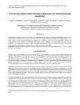
FIBER OPTIC SENSOR COUNTS SMALL OBJECTS
The D10 Expert Small Object Counter delivers high-performance small object counting to a variety of applications. Examples
include pharmaceutical pill counting, agricultural seed counting, process authentication, and verifying product flow from the
nozzle of a chute.
The Small Object Counter consists of a specialized D10 Expert sensor paired with preconfigured PFVCA fiberoptic arrays,
creating a two-dimensional sensing field in which objects are readily detected after breaking any point of the array. The
arrangement makes alignment easier and object-positioning control less critical than with traditional, single-point emitter and
receiver fiber optic assemblies. This ensures reliable, consistent, small object counting with response times as fast as 150 µs.
Three major features—Dynamic Event Stretcher (DES), Automatic Compensation, and Health Mode Alarm—make the counter an ideal solution for challenging small object counting applications. DES prevents double-counting translucent gel caps and
similar small objects, which may fool alternative sensing solutions. Both the
front and end edge of the object breaking the fiber optic array could activate
a traditional sensor, thus counting the object twice. With DES, the sensor
detects the front edge of the object and then stretches the duration of that
detection event, giving the object time to pass through the array without
being counted again.
Automatic Compensation allows the sensor to adapt the switching threshold to its environment in real time. Small changes due to dust or contamination on the fiber optic array or small changes caused by ambient temperature
shifts are filtered out by the microcontroller, providing consistent, repeatable
results.
Health Mode Alarm monitors the sensor’s performance. It alerts an operator
when preventative maintenance should be scheduled. This ensures continuous, reliable operation.
The D10 sensor costs $169. The fiber optic array costs $149.
Banner Engineering Corp.
www.bannerengineering.com
December 2009 – Issue 233
NPN
10
CIRCUIT CELLAR®
•
www.circuitcellar.com
npn233.qxp
11/11/2009
4:23 PM
Page 11
FPGA-BASED DEVELOPMENT BOARD
The NanoBoard 3000 is a programmable design environment,
supplied complete with hardware, software, a royalty-free IP, and
a dedicated Designer Soft Design license. Designers have
everything they need to explore FPGAs “out of the box.”
They are no longer forced to search the Internet for drivers, peripherals, or other software, and then have the
hard work of integrating all these elements to make
them work together.
Using the NanoBoard 3000, designers can construct sophisticated “soft”
processor-based systems inside FPGAs without any prior FPGA expertise. Engineers do not need any special VHDL or Verilog skills. Instead, they can use their
existing board layout and systems design skills to construct, test, and implement
FPGA-based embedded systems. The IP libraries and intuitive graphical editors that are central to Designer mean they can simply add processors, memory controllers, peripheral
blocks, and software stacks. They have everything they need to create next-generation,
FPGA-hosted embedded systems with off-the-shelf components without having to write
HDL or low-level driver code.
The first NanoBoard 3000 features a Xilinx Spartan 3AN FPGA. Two more NanoBoards,
featuring Altera and Lattice FPGAs, are planned. In all three NanoBoard options, the FPGA is
fixed. This distinguishes it from Altium’s NanoBoard NB2, which features interchangeable FPGA daughter boards to allow onthe-fly comparisons and testing in a prototype design environment.
The NanoBoard 3000 is available for $395. It includes a 12-month subscription to an Altium Designer Soft Design License,
which also includes software updates.
Altium Limited
www.altium.com
December 2009 – Issue 233
NPN
www.circuitcellar.com
•
CIRCUIT CELLAR®
11
npn233.qxp
11/11/2009
4:23 PM
Page 12
ispMACH 4000ZE PICO DEVELOPMENT KIT
The ispMACH 4000ZE Pico Development Kit is an easy-to-use, low-cost platform for evaluating and designing with ispMACH
4000ZE CPLDs. The kit is based on a 2.5″ × 2″ evaluation board that features the ispMACH 4256ZE device in a lead-free 144-pin
csBGA package, a Power Manager II POWR6AT6 for power monitoring, LCD panel, and an expansion header. The Pico evaluation board provides features to help evaluate the use of the ispMACH 4000ZE CPLD in the context of battery-powered, handheld application. CPLDs are ideal for glue logic, level-shifting between signal standards, and providing additional interfaces for
I/O limited microprocessors. On-board power-monitoring circuits with the POWR6AT6 device provide a convenient way to monitor power consumption of the CPLD. A USB cable programming interface allows for the modification of the CPLD programming
from a PC host. And by using ispLEVER Classic
and ispVM software, designers can compile their
own designs captured as VHDL, Verilog HDL, or
schematics.
The kit includes demonstration designs preprogrammed into the ispMACH 4256ZE and
POWR6AT6 devices that highlight key CPLD applications and power-saving measures to maximize
battery life. The CPLD demo design integrates an
up/down counter, right/left shift register, and an
I2C bus master controller that communicates with
the POWR6AT6. An LCD panel displays demo
output using three characters.
The development kit costs $69.
Lattice Semiconductor Corp.
www.latticesemi.com
DSP DEVELOPMENT TOOL WITH FULL EMULATION CAPABILITIES
December 2009 – Issue 233
For many designers, the cost and time to set up development tools is a major barrier when evaluating a new DSP platform.
To lower this barrier, Texas Instruments developed the TMS320VC5505 eZdsp USB stick development tool, which drops the
cost of a full-featured emulator and integrated development platform. This enables the rapid creation of DSP applications,
including portable audio players, voice recorders, IP phones, portable medical devices, biometric USB keys, software-defined
radios (SDRs), hands-free headsets, and metering applications. At this extremely low price point, it is the industry’s lowest
cost DSP tool, making development accessible to existing and potential customers, hobbyists, researchers, and students.
Comparable to the size of a stick of gum, the C5505 eZdsp stick simplifies development by providing integrated features
such as an on-board XDS100 emulator and on-board audio codec and connectors. Taking advantage of the energy-efficient
C5505 DSP, the eZdsp requires no other components or cables. Thus, the USB port powers
the entire development tool. Designers simply
plug into the USB port of any laptop or workstation for hassle-free development and a simple
out-of-the-box experience.
The feature-rich C5505 eZdsp USB stick
development tool is available now at the low
cost of $49, which includes a full XDS100 emulator and a target version of the industry-leading
CCStudio v.4. Special incentives are available for
educators, university students, and developers
actively participating in TI’s online community.
12
Texas Instruments, Inc.
www.ti.com
NPN
CIRCUIT CELLAR®
•
www.circuitcellar.com
npn233.qxp
11/12/2009
12:58 PM
Page 13
THYRISTOR SURGE PROTECTION
DEVICES
The enhanced MAX II CPLD family now
offers industrial-grade temperature ranges
and lower power requirements. The MAX
IIZ CPLDs’ combination of density, I/O, and
small package size, now with 55% lower
static power, make them an ideal fit for
cost- and power-sensitive applications.
These new capabilities open the devices
to a broader range of markets, such as
industrial, computer and office automation, medical, and consumer applications.
The MAX IIZ
CPLD was originally designed
for portable,
hand-held
devices, but the
enhanced versions enable
designers to
lower their power consumption and
reduce board space, thus lowering costs
in applications that were never previously considered for MAX IIZ devices.
The MAX IIZ EPM240Z M68 devices
are available now for $1.25 in high volumes. Additionally, over 20 MAX IIZ
design examples—enabling designers
to quickly and cost effectively create
and customize their designs—are available at www.altera.com.
Altera Corp.
www.altera.com
NPN
www.circuitcellar.com
•
CIRCUIT CELLAR®
ON Semiconductor
www.onsemi.com
FANL
CON
The
troller t
Based
troller b
December 2009 – Issue 233
MAX II CPLD ENHANCED
The NP-MC series is a new family of ultra-low capacitance Thyristor Surge Protection Devices (TSPDs) that
provide protection to sensitive electronic equipment from
transient overvoltage conditions. With capacitance values
40% to 50% lower than existing products on the market,
the NP-MC devices provide protection with minimal signal
distortion in high-speed xDSL, T1/E1 and other broadband
data transmission equipment.
Available with a full range of industry-standard voltage
levels and surge current ratings from 50 to 200 A, this
new series of TSPDs provides a solution for DSLAM, FTTx,
Ethernet, POE and VoIP systems. The low nominal offstate capacitance translates into extremely low differential
capacitance offering superb linearity with applied voltage
or frequency. Low leakage currents, precise turn-on voltages, and low voltage overshoot along with high surge
current capability underline the NP-MC series’ class-leading specification.
The new bidirectional, surface-mount devices enable
designers to achieve compliance with the various industry
regulatory standards such as GR-1089-CORE, ITU-TK.20/K.21/K.45, and IEC 60950. Housed in a small 2.6 mm
× 4.3 mm SMB package, the lead-free NP-MC series provides a space saving and cost-effective solution for
today’s high-speed wired communication networks.
The NP-MC series of devices are budgetary priced between $0.12 and $0.25
per unit in 10,000-unit quantities.
13
11/11/2009
4:26 PM
Page 14
S PECIAL
2912018_Tweed.qxp
FEATURE
by Dave Tweed
iMCU W7100
Embedded Networking Made Simple
The hardware TCP/IP stack of the W5100 has been enhanced in the W7100 with
the addition of an on-chip 8051 application processor core, eliminating the
need for a separate processor chip in many applications. Here’s an introduction
to the new chip and an evaluation module that’s based on it.
E
thernet connectivity for embedded systems has
been a hot topic for a while now, and WIZnet has a
nice family of products that makes Ethernet and TCP/IP
accessible to any microprocessor that has at least an SPI
interface. Their latest offering, the W7100 chip, takes it
one step further by integrating a general-purpose 8051
CPU core onto the same die, creating the possibility of
truly single-chip implementations for many low-end
applications.
This article will take you through some of the details of
the new chip and the development tools for it, and then
show you a complete application—a GPS-disciplined
Internet time server—that takes advantage of its
features.
and a special routine (called wizmemcpy()) is provided in
the boot ROM that supports a high-speed memory-tomemory transfer between TCP/IP core memory and CPU
memory.
Just to give you an idea of the levels of performance you
can expect, I tried out the WIZnet-supplied TCP loopback
server example. This is a simple server that sets up all
eight sockets in TCP mode, listening on port 5000. Any
data received on any socket is immediately sent back to
the originator. WIZnet also supplies a desktop program
called AX1 to communicate with the server. It has the
Media interface
December 2009 – Issue 233
THE W7100 CHIP
14
The W7100 chip is a combination of the same
hardware TCP/IP core used in the W5100 along
with a high-performance 8051-compatible CPU
core. The TCP/IP core includes 32 KB of data
buffer memory and supports eight simultaneous
sockets. In addition to the standard 8051 features,
the CPU core includes 64 KB of XDATA memory
(SRAM), 256 bytes of nonvolatile XDATA memory (flash), 64 KB of code memory (flash), and 2 KB
of boot code memory (ROM) (see Figure 1).
The TCP/IP core in the W7100 has basically the
same functionality as the standalone W5300 chip.
However, instead of an SPI or parallel interface, it
uses a dual-port memory arrangement with the
CPU core that can support higher performance.
Both the registers and the buffer memory of the
TCP/IP core are mapped into the 0xFExxxx block
of the CPU core’s 24-bit XDATA memory space,
Status LEDs
FEFFFF
TCP/IP
Core
TCP/IP
Interface
FE0000
00FFFF
RAM
External I/O
Timer 0
Timer 1
Timer 2
000100
000000
Flash
XDATA Memory space
FFFF
UART
Port 0
Port 1
Port 2
Port 3
8051
CPU
Core
Flash
0800
0000
ROM
CODE Memory space
FF
(Indirect)
80
SFRs
RAM
(Direct)
00
DATA Memory space
Fiigure
gure 1—This
1 —This shows two types of information, the block diagram of the
W7100 chip along with information about how the 8051 memory spaces are
laid out.
CIRCUIT CELLAR®
•
www.circuitcellar.com
11/11/2009
4:26 PM
Page 15
ability to send a file to the loopback server and
GPS Antenna
measure the overall throughput.
LCD
Right out of the box, this setup achieved about
1.6 Mbps overall, transferring a 1-MB file in about
5 seconds. However, I took a look at the code,
Motorola
DE9
Ethernet
W7100
RS-232
OnCore
RS-232
Connector
and it turns out that for every packet received,
jack
GT+
it was sending some debug information out the
UART port, and this turned out to be slowing
iMCU7100EVB Module
Serial cable
things down. When I removed the diagnostic
for firmware
updates
messages, the throughput approximately douDesktop PC
bled, to about 3.3 Mbps for the same size file.
Keil compiler
In the sample application that we’ll get into
Ethernet switch
WIZnet ISP
Telnet
later on, I’ve left the loopback server in place
Java beans
on the unused sockets so that you can see this
SNTP, TIME, DAYTIME Clients
for yourself.
To other PCs and Internet firewall
The processor core itself is a fairly generic
implementation with a moderate amount of
Figure 2—The hardware setup includes the iMCU7100EVB module along with the
on-chip I/O, including one UART, three timers,
Motorola OnCore GT+ GPS receiver module. The PC supports both code developand plenty of GPIO. It has the extensions
ment and operational testing.
required to support 24-bit XDATA memory
space, including two 24-bit DP registers for
memory-to-memory transfers.
program the small data flash area if you want.
The 64-KB code memory space is completely occupied
The second tool is a JTAG-based debugger interface. It
by on-chip flash memory, plus there’s a 2-KB ROM that
comprises a board with a fairly hefty FPGA on it, presumcan be overlaid over part of that space. There’s a dedicated ably for better performance. It connects to the PC via USB,
“boot mode” pin that determines the initial code memory and to the target via a small header. Unfortunately, I didn’t
configuration of the chip—whether it starts by executing
have enough time to check out this tool.
the boot loader in ROM or goes directly to the user application in flash.
THE iMCU7100EVB
The iMCU7100EVB evaluation module (mine says
iMCU7100API in the silkscreen) includes the W7100 chip
SOFTWARE DEVELOPMENT TOOLS
and an Ethernet connector (with built-in magnetics), along
The WIZnet folks recommend using the Keil suite of
with an RS-232 level translator for the UART. All of the
8051 software development tools (C compiler and assemchip’s external I/O is brought out to pads to which you can
bler, along with their “µVision” IDE), and as it happened,
solder either 0.100″ or 2-mm headers, and a special conI already had a copy of them installed from another projnector along one edge connects to the included 2 × 16 LCD
ect several years ago, so I was all set.
module. There’s also an array-of-pads prototyping area that
Each of the demonstration projects comes with a
supports both 0.100″ and 2-mm grids. (As you may recall,
µVision project file, but I ended up setting up a Makefile
2-mm headers were used for the W5100-based module used
and building the software from a Cygwin command line.
in the 2007 iEthernet Design Contest, causing issues for
It’s probably just my old-school mentality showing
some contestants. Obviously, WIZnet took that into
through, but generally the only thing I use IDEs for is
account here.)
simulating or debugging. For anything else, they just get
LEDs are provided both for the dedicated status outputs
in the way.
of the TCP/IP core, and for general use by application code
I was hoping to try out some alternative software tools,
on the CPU. A DIP switch sets the Ethernet operating
such as SDCC, but I ran out of time and didn’t get a
mode, and there are other switches for Power, Reset, and
chance to investigate that. However, based on my obserBoot mode.
vations with the Keil tools, it doesn’t look like there's
anything in the W7100’s CPU that can’t be programmed
with fairly generic tools.
SAMPLE APPLICATION
The sample application is an idea borrowed from the 2007
WIZnet iEthernet Design Contest, which featured the
DEVICE PROGRAMMING & DEBUGGING
W5100. Contestant Steven Nickels put together an Ethernet
The evaluation kit I received has two hardware development interfaces and PC-side software packages. The first is Time Server using the WIZnet module coupled with a
Freescale microcontroller and a WWVB receiver module. It
a simple in-system programmer for getting your code into
served up time in three ways, supporting the SNTP, TIME,
the chip. There’s a serial-port bootloader built into the onand DAYTIME protocols. This time around, I’ll use the
chip ROM, and a cable is provided to connect that to a
W7100’s built-in CPU and a GPS receiver module.
hardware port on your PC. A simple PC application takes
Steven’s project only kept track of time down to the
your hex file and gets it into the code flash. It can also
www.circuitcellar.com
•
CIRCUIT CELLAR®
December 2009 – Issue 233
2912018_Tweed.qxp
15
2912018_Tweed.qxp
11/11/2009
4:26 PM
Page 16
second, which makes sense for several
reasons. First of all, it’s tricky to get
more than that level of precision from a
WWVB receiver because of the nature
of the 1-bps signal. Also, the TIME and
DAYTIME protocols only have 1-second
resolution anyway.
On the other hand, a GPS receiver
can provide sub-microsecond precision
on its pulse per second (PPS) output
(typically down to ±50 ns in positionhold mode), and the NTP packet structure has timestamps with a resolution
of 2−32 second (about 230 ps). I’ve
always been interested in precision
timekeeping and frequency standards,
so I’m going to design my project to not
only implement the basic time-server
functionality, but also support eventual
construction of a full NTP server and a
GPS-disciplined reference oscillator.
December 2009 – Issue 233
THE REQUIREMENTS
16
The hardware requirements for this
project are simple. I have some
Motorola OnCore GT+ GPS receiver
modules that I purchased some time
ago. That defines that side of the
implementation—the W7100 is going
to have to communicate with one of
these modules using its binary protocol. The CPU will get the OnCore status messages via its serial port from
the receiver, along with the 1-PPS timing signal on a GPIO pin, providing
potential accuracy down to the
microsecond level.
On the LAN (software) side, we’ll be
running the TIME, DAYTIME, and
SNTP protocol servers, plus a Telnetbased console interface of my own
devising that has turned out to be a big
help during debugging. Also, keeping in
mind the future development of a highprecision system, the software timebase
will need a mechanism that allows it to
take into account any inaccuracy in the
CPU’s own clock. More about this when
we discuss the time module.
A few things to keep in mind for the
future would be to add a simple web
server for configuration, a DCHP client
for getting IP configuration information,
and perhaps an external hardware VCXO
(voltage-controlled crystal oscillator)
that would allow the system to be used
as a GPS-disciplined precision timing
reference. These are beyond the scope of
Photo 1—The W7100 chip in the center, which runs the show, is surrounded by the GPS
receiver module on the left, the 2 × 16 alphanumeric LCD above (this comes with the evaluation module), and a small RS-232 level converter on the right.
this article, but they’re definitely things
I’m interested in exploring soon.
THE DESIGN—HARDWARE
The hardware design is straightforward. Figure 2 shows a block diagram
of the overall system. Once the GPS
receiver is married to the WIZnet module (power, serial port, and PPS), the
only external interfaces are the antenna
connection to the receiver, the Ethernet
connection, and the WIZnet module’s
power supply (a wall wart).
I just needed to add a 10-pin female
header to the prototyping area to support the OnCore module. The only
quirk stems from the fact that the
OnCore serial interface uses TTL signal
levels, while the WIZnet board only
supports RS-232—there’s no provision
in the PCB artwork for disabling or
bypassing the RS-232 level converter.
As a result, I needed to add a small
TTL-to-RS232 converter module in
order to prototype this system.
The wall-wart power supply that
comes with the WIZnet board provides regulated 5.0 VDC, and an onboard linear regulator drops this down
to 3.3 V for the W7100. Both 5.0 V and
3.3 V are brought out to pads near the
prototyping area, so I got the 5 V that
the OnCore module requires there.
Photo 1 shows the entire system.
THE DESIGN—SOFTWARE
The software design is more
involved, but we’ll borrow heavily
from the WIZnet sample code and
Steven’s original implementation.
First, let me say a few words about
how the source code is structured. I’m
a firm believer in top-down, modular
design, abstraction and information
hiding. Over the years, I’ve developed
a scheme for structuring source code
that helps reinforce those concepts.
Each software module implements a
single logical piece of functionality,
such as a low-level UART interface or
a higher-level message protocol. To
the greatest extent possible, each
module presents an application programming interface (API) that is selfcontained and hides all details about
the underlying implementation.
I like to use short module names,
and then prefix each of the global
items belonging to that module (data
types, shared data, and function
names) with the name of the module.
This makes it immediately obvious
when reading some other module
where to go to get more information
about any item I see.
Take the UART interface as a specific
CIRCUIT CELLAR®
•
www.circuitcellar.com
11/11/2009
4:26 PM
Page 17
Listing 1—The header file for the sio module (sio.h) exposes only the interfaces that
other modules need. All implementation details are hidden in the code file (sio.c). Yes,
this module was indeed first developed in 1992, and I've been using it ever since!
/* sio.h */
/* Interrupt-based SIO driver for general breadboard use. */
/* History:
* 2009/09/13
* 2009/09/12
*
* 1992/11/24
*
* 1992/11/23
*/
DT
DT
DT
DT
add PARITY_NONE (8-bit data mode)
tweak data types for W7100 project
add baud rates supported by W7100
add 'sio_puthex', 'sio_put_ulong' and
'sio_status'
started
void sio_init (void);
#define B110
0
#define B300
1
#define B1200
2
#define B2400
3
#define B4800
4
#define B9600
5
#define B19200
6
#define B38400
7
#define B57600
8
#define B115200 9
#define B230400 10
#define B460800 11
void sio_set_baud (uint8 flag);
#define PARITY_SPACE 0
#define PARITY_MARK 1
#define PARITY_EVEN 2
#define PARITY_ODD
3
#define PARITY_NONE 4
void sio_set_parity (uint8 flag);
void
void
void
void
sio_putc (char ch);
sio_puts (char *s);
sio_puthex (uint8 n);
sio_put_ulong (uint32 n);
char sio_getc (void);
bool sio_status (void);
example. Typically, an application program is going to want to send bytes to
the interface, see if bytes are available in
the interface, and get those bytes if so. It
also may need to configure the interface
in terms of things like bit rate, parity,
flow control, etc. However, the rest of
the application code doesn’t—and
shouldn’t—care whether the underlying
implementation is polled or interruptdriven, what kinds of hardware/software buffering might be going on, or
www.circuitcellar.com
•
CIRCUIT CELLAR®
what register bits to twiddle to configure the port.
Therefore, the .h (header) file for the
sio module only exposes an abstract
set of functions and constants that the
application code can use to manipulate
the interface in exactly those ways (see
Listing 1). Note that unlike a lot of
other coders (embedded and otherwise), I have not put details about
hardware register addresses and bit
field definitions into this file—those
are implementation details that only
need to be known by the corresponding
.c (code) file. They either get defined
directly in that file, or indirectly by
virtue of including a different relevant
header file.
Many embedded applications have
multiple things going on in parallel, yet
they don’t really require the complex
interactions among threads that the typical RTOS (real-time operating system)
supports. Often, a simple “main loop”
that calls the different tasks in roundrobin sequence is more than sufficient,
and avoids many of the pitfalls of interrupt-driven thread switching in the first
place. I call this technique “pseudo-multithreading,” and it has worked well for
me for over 20 years.
With that in mind, take a look at the
overall structure of the software for this
project, as shown in Figure 3. The main
module serves only to get the system
initialized, and then it enters an infinite
loop, in which it calls the “go” function
for each module that has one. In this
case, we have six such modules: the five
socket servers—tp, dtp, sntp, loopback, and console—and the timebase
module (time).
The remaining modules perform support functions, called as needed by those
six. The lcd module puts ASCII information on the LCD, and the sio module implements the UART driver. The
socket module provides the abstract
logical interface to the WIZnet TCP/IP
core, while the wiz module hides the
low-level details of talking to a particular implementation. The wizmemcpy
module encapsulates the special highspeed memory-to-memory copy function
used on the W7100 chip. The oncore
and fifo modules support the console
module by implementing the receiverspecific message processing and a generic FIFO function, respectively.
We can establish some specific lines
of communication among the modules
that are required for this project. For
example, each of the time server modules needs to be able to get the current
time from the time module, in addition
to servicing its assigned socket via the
socket module. The loopback module has no connections other than the
one to the socket module.
The console module has several
December 2009 – Issue 233
2912018_Tweed.qxp
17
2912018_Tweed.qxp
11/11/2009
4:26 PM
developed back in the early
1990s while working on
some commercial telecomindustry firmware. It is comTp
Dtp
Sntp
Loopback
Console
Oncore
pletely interrupt-driven, with
large FIFOs in each direction,
and supports all the baud
rates and all the parity modes
for 7-bit data. The only
Fifo
Socket
tweaks I needed for this project were to add some of the
higher bit rates that the
W7100 supports, and the
Lcd
Time
Wiz
Sio
wizmemcpy
PARITY_NONE mode to support the 8-bit binary data
Figure 3—The software is broken up into modules. The ones with
used in the OnCore interface.
heavy borders represent the top-level “threads” that run concurThe console module can
rently, called in round-robin fashion by the main module. The othaccept data from either the
SOCKET INTERFACE
ers are support libraries and low-level drivers. The lines between
UART or its Telnet socket,
I started out by looking
them show how they communicate.
and it can send diagnostic
at the implementation of
of the registers had dedicated access
output messages to either or both
the TCP loopback server supplied by
functions, and this led me to the fact
paths as well. Any of the other modWIZnet, since three of the four
ules can send diagnostic messages by
servers I wanted to implement would that the driver can use an interrupt
from the TCP/IP core to pick up cercalling console_print(), and they
involve TCP. The “TCPS” project as
tain status changes, but not all. It
don’t need to know which path is actusupplied by them is broken into
turns out that the driver must explically in use at the time. An internal flag
three layers, with the loopback moditly poll the hardware for each packet
tells console whether the UART is
ule at the top, a socket abstraction in
send or receive operation, without
being used for diagnostics, and this flag
the middle, and an iinchip module
using the status-interrupt mechanism.
can be set/cleared on the fly by calling
providing the low-level interface to the
This caused quite a bit of head-scratch- console_enable_sio().
TCP/IP core.
ing until I discovered this detail.
I reviewed the source code and felt
At the moment, the console modI also made a pass through the
there was a lot of information shared
ule is probably the messiest one in
loopback module itself, which
among the three layers. For example,
terms of its internal logic, and it also is
implements the top-level state
the iinchip module provided functhe one that will change the most as
machine for any TCP server. You can
tions to read and write 8-bit registers
the project evolves. In its present state,
use this module as a template for any
in the interface, but no support for
console_print() only goes to the
TCP-based service, and I have in fact
the several 16-, 32-, and 48-bit regisTelnet connection, any data received
left it in place on the otherwise
ters—the socket module had long
via Telnet is translated into binary
unused sockets in this design.
strings of 8-bit reads and writes to
form and forwarded to the OnCore
deal with them instead.
module via the UART, and any data
So, partly for that reason, and partly
coming from the OnCore module is
THE CONSOLE
to force myself to examine and underconverted to readable ASCII form and
The next thing I implemented was
stand all of the code, I started rewritforwarded to the Telnet connection. In
a generalized console (debug) intering both modules in my own style and
addition, if the message from the
face. I knew that at first, I would be
tweaking the interface between them.
OnCore module is recognized as a stausing the UART port for debugging
The first thing I did was to rename the
tus message (starting with “@@Ea”), it
some of the TCP/IP code, but then I
iinchip module to wiz, and to start
is parsed into a data structure, and
would later need to devote this port
putting the wiz_ prefix on all the
to the GPS receiver, and so it seemed then the time and date fields from this
function names. This would allow the
logical to provide a Telnet server that structure are used to set the timebase.
compiler to help me catch anything I
provided the same kind of access.
I also retained the LCD interface
might otherwise miss translating.
Doing this helped reinforce the
from the original TCPS project. It
I created functions like
knowledge I picked up while studyshows some start-up information, but
wiz_read16() and wiz_write16()
ing the loopback module. In addithen the time module takes it over
(along with 32- and 48-bit versions)
tion, rather than using the extremeand displays the current date and
and made the corresponding changes
ly-simple polled UART driver code
time, updated every second.
in socket, which made the overall
that WIZnet used, I pulled out my
logic of that module much clearer.
tried-and-true interrupt-based 8051
THE TIMEBASE
Along the way, I discovered that some
UART driver (called sio) that I
The software I’ve described up to this
December 2009 – Issue 233
connections. In addition to
the aforementioned support
modules, it has a socket
interface running a Telnet
server (on port 23) for general
debugging, it can call into the
time module in order to set
or adjust the system clock,
and it uses the sio module to
communicate with the GPS
receiver. The latter interface
can also be used for debugging when the receiver is not
connected, which is useful for
debugging details of the
TCP/IP interface.
18
Page 18
Main
CIRCUIT CELLAR®
•
www.circuitcellar.com
5.qxp 9/2/2009 4:24 PM Page 1
Ja eco_CC_ _Oct09 8/ /09
: 5
age
What is
the missing
component?
Industry guru Forrest M. Mims III has created a stumper. Video game
designer Bob Wheels needed an inexpensive, counter-clockwise
rotation detector for a radio-controlled car that could withstand the
busy hands of a teenaged game player and endure lots of punishment.
Can you figure out what's missing? Go to www.Jameco.com/unravel
to see if you are correct and while you are there, sign-up for our
free full color catalog.
1-800-831-4242
2912018_Tweed.qxp
11/11/2009
4:26 PM
Page 20
USING TELNET
Using the Telnet protocol
(RFC854) to connect to your project is very straightforward. Pretty
much every operating system has a
command-line Telnet client—usually called “telnet”—and most
GUI-based terminal emulators
support Telnet as well.
To get started, just get to a
command prompt on your desktop system and type “telnet
<host>,” where <host> is either
an IP address or a host name that
is known to your system. For
example:
# telnet 192.168.1.20
Trying 192.168.1.20...
Connected to 192.168.1.20.
Escape character is '^]'.
December 2009 – Issue 233
From then on, everything you type
will be sent to the remote system
on a line-by-line basis each time
you hit <CR>, and anything the
remote system sends back will be
displayed.
Make note of the escape character; that’s how you’ll get out when
you’re done. It isn’t the same thing
as the Escape key—that would be
‘^[‘—you really have to hit Ctrl-].
At that point, you’ll get a prompt
from the client program on the
local system, and you can type
“quit” to terminate the session or
“help” for additional commands.
20
point can be characterized as generic
infrastructure code that would be applicable to pretty much any application.
Here’s where we start to get into the
details of the time server application in
particular. There are two parts to this:
setting up a timebase based on the CPU
clock (accessed by means of the hardware timer modules) and setting/calibrating that timebase using data found
in the OnCore GPS messages.
Ultimately, the CPU’s crystal is the
timing reference for the timebase. On
the W7100, the 11.0592-MHz crystal
frequency is multiplied by eight to get a
raw CPU clock of 88.4736 MHz. (You
might recall that 11.0592 MHz is a convenient value for generating standard
UART bit rates.) The raw CPU clock
gets divided by 12 (7.3728 MHz) to create the clock that drives the hardware
timers.
I reserved Timer 1 to generate the
UART bit rate clock, so that left Timers
0 and 2 for use in the application timebase. I eventually want to use Timer 2
to accurately capture the PPS signal
from the GPS receiver, which leaves
Timer 0 for generating a fundamental
“tick” interrupt that can be used to
measure the passage of time. It turns out
that the most convenient tick rate (i.e.,
one that’s an integer multiple of 1 Hz)
that I can get using this combination of
clock frequency and the divider ratios
available in Timer 0 is 900 Hz.
One thing we’re going to have to
keep in mind is that the 11.0592-MHz
crystal is just a generic unit, with probably on the order of ±100 ppm accuracy. Since I eventually want to be able
to establish a “virtual” timebase that’s
a couple of orders of magnitude better
than this (on the order of 1 ppm or better), I need a mechanism that will
allow the passage of time per software
tick to be adjusted by small amounts. I
borrowed the technique used in direct
digital synthesis (DDS) frequency generators. It works as follows.
I maintain three variables to record
the passage of time: a 32-bit picosecond
counter, a 16-bit millisecond counter,
and a 32-bit seconds counter. I also have
a variable called ps_per_tick, which is
initialized to a particular value, but can
be adjusted on the fly. With a nominal
tick rate of 900 Hz, there should be
1,111,111,111 ps per tick. This is a number that just fits into a 32-bit variable.
For each tick interrupt that occurs, the
ps_per_tick value gets added to the
picosecond accumulator. Then, as long
as the picosecond accumulator is greater
than 1,000,000,000, that value is subtracted from the accumulator and the
millisecond accumulator is incremented.
This will happen once or twice per tick,
depending on the starting value of the
picosecond accumulator. Finally, each
time the millisecond counter reaches
1,000, it gets cleared and the seconds
counter gets incremented. The seconds
counter simply counts seconds from
the start of January 1, 1900—it will
overflow sometime in the year 2036.
You can see that this setup allows
1-LSB adjustments of the ps_per_tick
value to vary the perceived rate of
time by about 1 ppb, which is more
than enough resolution (about 32 ms per
year) to reach my goals. After experimenting with this for a while, I discovered that the crystal on my particular
board runs about 80 ppm fast, (gaining
almost 7 seconds per day); so for now, I
initialize ps_per_tick to 1,111,022,229
and leave it there. It currently keeps time
on its own to better than 0.5 s per day.
The next part of the problem is to get
the counters set to the correct value,
based on the information coming from
the GPS receiver. The oncore module
(software) takes care of the details of
communicating with the OnCore module (hardware) using its binary protocol.
There are several useful functions here:
oncore_create() takes a “generic
ASCII” representation of an OnCore
message (one that can be typed by a
user) and turns it into the “pure binary” form that the OnCore expects,
while oncore_process() does the
opposite. These are useful for testing
the interface. The specific message
we’re interested in is the “@@Ea” status message, so there are two functions
specific to that: oncore_parse_Ea()
reads the contents of that message and
puts the information into a C structure
for use by the other modules, and
oncore_show_Ea() prints the contents of that structure to the console for
monitoring what’s going on. It’s actually the console module that pulls the
date and time information out of that
structure and then calls time_set() to
synchronize the software timebase with
the real world.
For now, that’s all I’m doing—forcing
the seconds counter to the value that
represents the same time that’s in the
GPS message. I’m not (yet) making any
attempt to synchronize the picosecond
and millisecond counters to the 1-s
boundaries, which means that there’s
still up to 1 s of difference between
internal time and external time. The
next step will be to use the rising edge
of the PPS signal coming from the GPS
module to take care of that detail.
Eventually, I’ll be setting up a software phase-locked loop (PLL) that
drives the software timebase into
CIRCUIT CELLAR®
•
www.circuitcellar.com
11/11/2009
4:26 PM
Page 21
exact alignment with the PPS signal
by dynamically adjusting the
ps_per_tick value. This will also
give me a more precise measurement
of the CPU crystal’s frequency error.
THE TIME SERVERS
With the software timebase set up,
it’s actually quite straightforward to
implement the time server modules
themselves. Both TIME protocol and
DAYTIME protocol are TCP services, so
I took the generic TCP state machine
from the TCPS loopback module, and
then dropped Steven’s data-handling
code into them, creating the tp and
dtp modules, respectively. SNTP protocol is UDP-based, so I went to the WIZnet UDP loopback example to get the
template for the sntp module, and put
Steven’s packet-building code into it,
making suitable adjustments.
Steven had some Java client code for
all three protocols that runs on a PC
that he used to test his server, and I figured that a fair test of my implementation would be to see whether it works
with those clients. After getting the latest versions of Java and Java Beans from
the Sun website, I was able to adjust the
hard-coded IP addresses and compile the
clients. Everything worked just fine!
I figured the real acid test would be
to see whether a Windows machine
would actually be willing to synchronize with my server (all versions from
Windows 2000 on have SNTP built in).
It turned out that Steven had some of
the timestamps in the wrong places in
his SNTP packet, but after a simple
adjustment, my Win2K machines were
happy with the setup. Also, I took
advantage of my millisecond counter to
add some fractional-second information
to the timestamps, which makes it easier to see how well things are tracking.
FUTURE DIRECTIONS
I hope that you will find some of the
modules in the code accompanying
this article a useful base for your own
W7100 projects. In terms of this particular project, I’m not sure if the Motorola OnCore series of GPS receivers is
still available on the surplus market,
but it should be straightforward to
replace the oncore module with an
NMEA sentence parser to allow the
www.circuitcellar.com
•
CIRCUIT CELLAR®
use of most other GPS receiver modules.
As I said before, I plan to continue
development of this project to support
precision timing and frequency, and if
I come up with something interesting,
I’ll write a follow-up article. I’d also
like to add additional TCP/IP features
to the project, such as a DHCP client
and a simple HTTP server. I’ve seen
some interesting work regarding the
use of client-side Javascript to create
relatively rich web interfaces for
embedded systems that I’d like to
explore. I
David Tweed (dtweed@acm.org) is a hardware and real-time firmware engineering consultant who has been working with embedded processors starting in 1976 with the Intel
8008. His system design experience includes computer design from supercomputers to
workstations, digital telecommunications systems, and the application of embedded
microcomputers and DSPs. He is also a Circuit Cellar project editor and quiz master.
When not playing with electronics and software, he pursues his hobby as an amateur
musician, playing keyboards and low brass instruments in several community groups.
P
ROJECT FILES
To download the code and additional content, go to ftp://ftp.circuitcellar.
com/pub/Circuit_Cellar/2009/233.
R
ESOURCES
D. Mills, “RFC2030: Simple Network Time Protocol,” Network Working
Group, 1996.
Motorola, OnCore Manual, www.wa5rrn.com/oncore.htm.
S. Nickels, “Time Server Design: Synchronize with the WWVB Time Code
Signal,” Circuit Cellar 220, 2008.
———, Time Server Project, www.circuitcellar.com/Wiznet/winners/001066.
html.
J. Postel, “RFC867: Daytime Protocol,” Network Working Group, 1983.
J. Postel and K. Harrenstien, “RFC868: Time Protocol,” Network Working
Group, 1983.
WIZnet, “Internet Embedded MCU W7100 Datasheet,” Ver. 0.9 Beta, 2009.
WIZnet Wizwiki, http://wizwiki.net/forum/.
S
OURCES
GNU Tools on Windows
Cygwin | www.cygwin.com
RSLink Module
Embed, Inc. | www.embedinc.com/products/ser/
8051 Compiler tool
IAR Systems | www.iar.com
Keil | www.keil.com
Java Beans
Sun Microsystems | www.java.sun.com
W7100 Evaluation module/kit
WIZnet | www.wiznet.co.kr
December 2009 – Issue 233
2912018_Tweed.qxp
21
40-41.qxp
8/5/2009
9:53 AM
Page 40
40-41.qxp
8/5/2009
9:53 AM
Page 41
11/11/2009
4:27 PM
Page 24
F EATURE
2912014_Edwards.qxp
ARTICLE
by Stephen A. Edwards
Retrocomputing on an FPGA
Reconstruct an ’80s-Era Home Computer with
Programmable Logic
If you’re interested in preserving legacy digital electronics and integrating
them with modern systems, this article is for you. Get ready to reconstruct
the venerable Apple II+ with programmable logic.
December 2009 – Issue 233
A
24
s a Christmas gift to myself in 2007, I implemented
a 1980s-era Apple II+ in VHDL to run on an Altera
DE2 FPGA board. The point, aside from entertainment, was
to illustrate the power (or rather, low power) of modern
FPGAs. Put another way, what made Steve Jobs his first
million could be a class project for the embedded systems
class I teach at Columbia
University.
More seriously, this project
demonstrates how legacy digital electronics can be preserved and integrated with
modern systems. While I didn’t have an Apple II+ playing
an important role in a system, many embedded systems last far longer than
their technology. The space
shuttle immediately comes
to mind. Another example is
that DEC PDP-8s are found
running some signs for San
Francisco’s BART system.
Designed by Steve Wozniak (“Woz”) and introduced in
1977, it really took off in 1978 when the 140-KB Disk II
5.25″ floppy drive was introduced, followed by VisiCalc,
the first spreadsheet.[1,2,3]
Fairly simple even by the standards of the day, the
WHAT’S AN APPLE II+?
The Apple II+ was one of
the first really successful personal computers (see Photo 1).
Phhoto
oto 1
1—The
— The Apple II+ was designed by Steve Wozniak and introduced in 1977.
CIRCUIT CELLAR®
•
www.circuitcellar.com
11/11/2009
4:27 PM
Page 25
Apple II was built around the inexpensive 8-bit 6502
processor from MOS Technology. (It sold for $25 when an
Intel 8080 sold for $179.) The 6502 had an 8-bit data bus
and a 64-KB address space. In the Apple II+, the 6502 ran
at slightly above 1 MHz. Aside from the ROMs and
DRAMs, the rest of the circuitry consisted of discrete LS
TTL chips (see Photo 2).
While the first Apple IIs shipped with 4 KB of DRAM,
this quickly grew to a standard of 48 KB. DRAMs, at this
time, were cutting-edge technology. While they required
periodic refresh and three power supplies, their six-times
higher density made them worthwhile.
Along with an integrated keyboard, a rudimentary (1-bit)
sound port, and a game port that could sense buttons and
potentiometers (e.g., in a joystick), the main feature of an
Apple II+ was its integrated video display. It generated
composite (baseband) NTSC video that was usually sent
through an RF modulator to appear on TV channel 3 or 4.
The Apple II+ had three video modes: a 40 × 24 uppercase-only black-and-white text display, a 40 × 48 16-color
low-resolution display, and a 140 × 280 six-color high-resolution display. The Apple II+ can almost be thought of as a
video controller that happens to have a microprocessor
connected to it. Woz started with a 14.31818-MHz master clock—exactly four times the 3.579545-MHz colorburst frequency used in NTSC video—and derived everything from it. The CPU and video alternate accesses to
memory at 2 MHz. Another Woz trick: the video addresses are such that refreshing the video also suffices to
refresh the DRAMs, so no additional refresh cycles are
needed.
Figure 1 shows the block diagram of my reconstruction. The 6502 processor on the left generates addresses
and output data. The address is fed to the ROMs, an
address range decoder, the peripheral slots, and a mux
that selects between processor and video system addresses for the main memory. The original Apple II+ used a
tristate data bus, but FPGA cores do not support such
complex electrical structures (although they do provide
tristate I/O pins), so my reconstruction breaks the data
bus into multiple segments. Most notably, I added a
large mux (on the right side of Figure 1) that selects the
source of data fed to the 6502 core, such as main memory or the ROMs.
THE CLOCK GENERATOR
Figure 2 shows the Apple’s clock generator circuit. A
crystal oscillator drives the clocks on a ’195 quad shift
register and a ’175 quad flip-flop. These generate clocks
for the DRAM (RAS’ and CAS’) along with the “1 MHz”
processor clocks PHI0 and PHI1. A gated version of PHI0
feeds a bank of ’161s: 4-bit binary counters configured to
act as horizontal and vertical counters (H0–H5, VA–VC,
and V0–V5) from which the video addresses are generated.
This clever circuit does a lot with few parts. It is at
the center of Woz’s patent, which describes it and his
trick of using digital signals to generate color NTSC
www.circuitcellar.com
•
CIRCUIT CELLAR®
Photo 2—This is the Apple II+’s motherboard. Expansion slots and
analog video circuitry dominate the top. The 6502 is above the six
large ROM chips. The white rectangle encloses 48 KB of DRAM. The
character ROM is at the bottom. The rest is TTL.
video.[4] Woz derived the CPU clock from the 14 MHz
clock by dividing by roughly 14. I write “roughly”
because every sixty-fifth CPU cycle (one per horizontal
scan line) is stretched by two 14-MHz clock periods to
preserve the phase of the 3.58-MHz colorburst frequency.
Thus, there are 912 (i.e., 65 × 14 + 2) pixel periods per
line, or exactly 228 cycles of the 3.58-MHz colorburst
per line.
While it would be possible to write a model for each
TTL part in VHDL and assemble them according to the
schematic, I prefer to try to write the VHDL according
to Woz’s intentions for the original circuit. This is especially true for combinational “glue” logic, which was
often implemented in nonintuitive ways to save parts.
Listing 1 shows my VHDL code for the clock generator. It assumes the 14-MHz clock is provided externally
December 2009 – Issue 233
2912014_Edwards.qxp
25
2912014_Edwards.qxp
11/11/2009
4:27 PM
December 2009 – Issue 233
and consists of three main sequential
processes. The first models the ’195
shift register, which either shifts or
loads depending on its own Q3 output. The second process models the
’175 quad flip-flop and the ’153 driving it, which selects between
PRE_PHI_0 and a combination of Q3
and PHI0 depending on the state of
AX. The third sequential process
models the four 4-bit binary counters. In the original circuit, these
were clocked by the output of a
NAND gate. Such a practice is dangerous because the output of the gate
might glitch and cause unpredictable
behavior, so instead I chose to clock
these counters at 14-MHz and carefully control when they count.
Figure 3 shows a timing diagram
for the clock generator and illustrates how it behaves at the end of a
line. The COLOR_DELAY_N signal
causes the shift register to delay
RAS_N et al two extra 14-MHz
cycles, which also causes PHI0 to be
stretched. HCOUNT changes on the
26
Page 26
Timing
generator
A
6502
Video
generator
Address
mux
Memory
Data
latch
D_out
D_in
ROM
Keyboard
Game port
Address
decorder
Data
mux
Speaker
Peripheral slots
Figure 1—This is a block diagram of my reconstruction.
rising edge of LDPS_N, just as in the
original circuit.
The values taken on by the horizontal
counter are a little unusual: the
counter is allowed to wrap around
from 7F to 00, but is then set to 40
Figure 2—Woz’s clock generator circuit includes a 14.31818-MHz crystal that drives a 4-bit shift register and a quad flip-flop to generate
DRAM timing signals and the processor clocks, which in turn feed a bank of horizontal and vertical video counters.
CIRCUIT CELLAR®
•
www.circuitcellar.com
11/11/2009
4:27 PM
Page 27
to start the line. These 65 PHI0 periods turn into about 15.70 kHz, close
to the NTSC horizontal frequency of
15.734 kHz.
making sure the tristate data pins
are only driven when the processor
is writing to the RAM.
THE CPU & MEMORY
The Apple II+ has three main
video modes: a 40 × 24 uppercaseonly text display, a 40 × 48 16-color
“low-res” graphics mode, and a 280
× 192 6-color “high-res” graphics
mode. The graphics modes also have
a mixed mode in which the bottom
four lines of text are displayed
instead.
The memory layout for all three
modes is similar and nonlinear. To
accommodate 40-character text lines
using only a single 4-bit binary adder
and wasting little memory, Woz
divided the screen into three horizontal stripes, each 64 scan lines
high (equivalently, eight character
rows). Memory for each display
mode is divided into 128-byte segments that hold three 40-byte lines
(i.e., the last eight bytes in each segment are not displayed). The first
line in each segment appears in the
top stripe, the second in the middle
stripe, and the third in the bottom.
The result is that bits 3 to 6 of the
video address are a funny sum of
horizontal and vertical counter bits.
All three modes fetch 1 byte from
video memory every PHI0 cycle. In
Text mode, the data is fed to the top
six address bits of the character ROM,
and the output of the ROM is loaded
into a ’166 8-bit parallel-to-serial shift
Like Woz, I didn’t create a 6502
processor from scratch. Instead, I
used a 6502 core written by Peter
Wendrich for his FPGA-based Commodore 64. The main challenge here
was making sure it was clocked properly given the odd way the Apple II+
generates its occasionally stretched
processor clock.
Semiconductor memory has changed
a lot since 1977. The Apple II+ used 24
4116 16-kb DRAM chips with 150 ns
access times to provide 48 KB of
memory. Today, it is difficult to find
memory chips this small.
While it would have been nice to
place all of the Apple’s memory on
the FPGA I was using, the Altera
Cyclone II 2C35 has about 59 KB of
on-chip RAM, which is just a little too
small to fit 48 KB of RAM plus 12 KB
of ROMs. I chose instead to use offchip SRAM (the DE2 has 512 KB) for
the 48 KB of main memory and store
the ROMs on-chip. Storing the
ROMs in FPGA memory is more
convenient because their contents
are initialized when the FPGA is
programmed.
Asynchronous SRAM is much easier to interface than DRAM. The only
real issue is generating an appropriately timed write enable signal and
62 us
Time
CLK_14M
RAS_N
AX
cas_n
Q3
VIDEO GENERATOR
63 us
register. In low-res mode, the byte is
loaded into a pair of 4-bit recycling
shift registers and clocked out
repeatedly. In high-res mode, the
byte is loaded into an 8-bit shift register and clocked out.
VGA LINE DOUBLER
The Apple II+ generates a composite color NTSC signal that was usually sent through an RF modulator
and displayed on a standard television set. Since computers have not
used composite color monitors since
the early 1980s, one of my goals was
to generate an analog color VGA signal (now also obsolete) suitable for a
standard computer LCD monitor.
This presented two problems. The
first is one of rate. The Apple II+
generates composite color non-interlaced NTSC video: 60 frames a second, 262 lines per frame. This leads
to a horizontal refresh rate of about
15.70 kHz.
The VGA standard, which has been
around since 1987, is an analog RGB
component format associated with a
variety of refresh rates, but the most
relevant here is essentially NTSC
times two: a 31-kHz horizontal
sweep rate with a 60-Hz frame rate.
By design, this is two VGA lines for
every NTSC line.
So, to display an NTSC-rate image on
a VGA monitor, it is enough to display
each NTSC line twice, which is convenient because it only requires buffering a line instead of a whole frame.
64 us
65 us
CLK_7M
COLOR_REF
PRE_PHI0
PHI0
LDPS_N
HPE_N
HCOUNT[6:0]
VCOUNT[8:0]
COLOR_DELAY_N
7E
0FA
7F
00
0FB
Figure 3—This timing diagram shows the behavior of the clock generator at the end of a line.
www.circuitcellar.com
•
CIRCUIT CELLAR®
40
41
December 2009 – Issue 233
2912014_Edwards.qxp
27
41.qxp
1/7/2009
3:07 PM
Page 1
63.qxp
1/7/2009
3:20 PM
Page 1
2912014_Edwards.qxp
11/11/2009
4:27 PM
Rather than redesign Woz’s carefully
crafted video circuitry, I chose to
place a VGA line doubling circuit
after his 1-bit video output that both
doubles the horizontal frequency and
interprets color information.
My circuit consists of a dual-ported memory that stores two lines of
the 14-MHz 1-bit video signal. At
any time, the circuit is filling in one
line and displaying the other; the
roles of the two lines swap once
every NTSC line.
December 2009 – Issue 233
COLOR DECODER
30
Interpreting colors is the bigger
challenge in converting the Apple II+
output to color VGA signals. Unlike
VGA, which conveys separate red,
green, and blue signals, composite
(color) NTSC video consists of three
signals modulated together. To a
high-bandwidth luminance (brightness only) signal (about 3 MHz)
called Y, NTSC adds two lower-bandwidth color signals (“I” and “Q”)
that are quadrature modulated at
3.579545 MHz. A color television
demodulates and combines linear
ratios of these signals to recover red,
green, and blue intensities.
The Apple II+ uses a trick to generate the modulated signal: it produces
a digital signal that switches at
14.31818 MHz—exactly four times
the colorburst frequency. Figure 4a
depicts a small patch of this digital
video output interpreted as black and
white pixels. The 16 different periodfour waveforms (i.e., whose fundamentals are at the 3.58-MHz colorburst frequency) each produce a different color (two produce gray). All
0s is black and all 1s is white since
neither has any high-frequency information; the television interprets
them as purely luminance. Other
patterns produce different levels of Y,
I, and Q, and thus different colors.
NTSC demodulation and YIQ-toRGB colorspace conversion is a linear
process, albeit a time-varying one
because quadrature modulation uses
phase to distinguish two signals. So,
the digital video signal the Apple II+
produces can be thought of as a linear
combination of four square wave signals that differ only in their phase.
Page 30
Listing 1—This is my VHDL code for the clock generator.
-- To generate the once-a-line hiccup: D1 pin 6
COLOR_DELAY_N <=
not (not COLOR_REF and (not AX and not CAS_N) and PHI0 and not H(6));
-- The DRAM signal generator
C2_74S195: process (CLK_14M)
begin
if rising_edge(CLK_14M) then
if Q3 = '1' then -- shift
(Q3, CAS_N, AX, RAS_N) <=
unsigned'(CAS_N, AX, RAS_N, '0');
else
-- load
(Q3, CAS_N, AX, RAS_N) <=
unsigned'(RAS_N, AX, COLOR_DELAY_N, AX);
end if;
end if;
end process;
-- The main clock signal generator
B1_74S175 : process (CLK_14M)
begin
if rising_edge(CLK_14M) then
COLOR_REF <= CLK_7M xor COLOR_REF;
CLK_7M <= not CLK_7M;
PHI0 <= PRE_PHI0;
if AX = '1' then
PRE_PHI0 <= not (Q3 xor PHI0); -- B1 pin 10
end if;
end if;
end process;
LDPS_N <= not (PHI0 and not AX and not CAS_N);
LD194 <= not (PHI0 and not AX and not CAS_N and not CLK_7M);
-- Four four-bit presettable binary counters
-- Seven-bit horizontal counter counts 0, 40, 41, ..., 7F (65 states)
-- Nine-bit vertical counter counts $FA .. $1FF (262 states)
D11D12D13D14_74LS161 : process (CLK_14M)
begin
if rising_edge(CLK_14M) then
-- True the cycle before the rising edge of LDPS_N: emulates
-- the effects of using LDPS_N as the clock for the video counters
if (PHI0 and not AX and ((Q3 and RAS_N) or
(not Q3 and COLOR_DELAY_N))) = '1' then
if H(6) = '0' then H <= "1000000";
else
H <= H + 1;
if H = "1111111" then
V <= V + 1;
if V = "111111111" then V <= "011111010"; end if;
end if;
end if;
end if;
end if;
end process;
Thus, interpreting groups of 4 bits as
one of 16 colors produces a reasonable display, especially for solid
regions.
Unfortunately, this 4-bit-at-a-time
approach produces more color fringing around the edges of white objects
than a television would because of
the bandwidth limits on I and Q, as
shown in Figure 4c. My solution was
to look at one bit to the left and
right of the four-bit window and generate color only when these extra
bits follow the same pattern as the
middle four (see Figure 4d).
Figure 5 shows an abstract view of
my color generator. At the top is a 6-bit
shift register that amounts to a sliding
CIRCUIT CELLAR®
•
www.circuitcellar.com
2912014_Edwards.qxp
11/11/2009
a)
b)
c)
d)
4:27 PM
Figure 4—This is a high-res graphics fragment interpreted as (a) monochrome,
(b) output from the KEGS software emulator for the Apple IIGS, (c) under a 4-bit window algorithm, and (d) under the 6-bit window algorithm used in my reconstruction.
window into the video signal. Each bit
consumes 90° of phase; the circuit
Page 31
on how many bits are set in the middle two positions in the shift register. This approximates the effect of
the lower I and Q bandwidth: when
the signal suddenly changes from
dark to light, the luminance changes
more quickly; the color information
changes slower.
It took some experimentation for
me to arrive at this approximation.
To evaluate the algorithms, I wrote a
simple C program that converted a
memory dump of a high-res image
into a PPM file, which I then evaluated. Figure 4d is the output I finally
implemented.
mostly considers the middle 4 bits.
The main color circuitry comprises
a “permute” block that rotates the
four (constant) basis colors depending
on which of the four phases a pixel
can be in relative to the colorburst
frequency. Then each of the four basis
colors are ANDed with the four middle bits of the sliding window filter
and added together to form a 24-bit
RGB value.
At the top right of Figure 5 are
three gates that guess when we are in
the middle of a solid color region.
When bits 0 and 4 in the filter are
equal and bits 1 and 5 are also equal,
the “color select” signal is true and
the solid color value generated as
described above is selected as the
color for this pixel.
Otherwise, my circuit colors the
pixel black, gray, or white depending
THE DISK II EMULATOR
Introduced about a year after the
Apple II itself, the Disk II 5.25″ floppy disk drive was another remarkably svelte piece of hardware.[2, 5] The
Colorburst phase
Shift register
Color select
White select
Gray select
Phase angle
Black select
Black
Dark red
Gray
White
Color mux
Pixel out
Dark blue
+
Color
Dark blue-green
Dark brown
Figure 5—This is an abstract view of the color generator.
www.circuitcellar.com
•
CIRCUIT CELLAR®
December 2009 – Issue 233
Permute
31
2912014_Edwards.qxp
11/11/2009
4:28 PM
which interprets CPU access to the
relevant I/O addresses, and a SPI
module that fetches blocks of data
from an SD card based on commands
from the first module.
SD/MMC flash memory cards can
be operated in a variety of modes.
The simplest is SPI, a simple, welldocumented, four-wire synchronous
serial protocol. Furthermore, the
wiring on the DE2 was clearly set up
to operate SD cards in such a mode.
The Disk II presented an extremely low-level interface to software.
Head positioning was performed by
directly activating the stepper motor
phases in sequence. And although
the hardware did provide a facility
for clock recovery and framing, the
software was presented with just a
raw stream of encoded bytes from
the disk.
Instead of the FM scheme used by
the Shugart controller—which placed
a clock pulse between every data
pulse—the Disk II used a group code
recording scheme that allowed up to
two consecutive 0s before a 1 was
mandatory, making it possible to
store 6 bits instead of 4 in the space
of eight transitions. This improved
formatted capacity to 140 KB per
diskette over the 90 KB possible with
FM encoding, but it fell to the software to decode this data.
My Disk II emulator consists of a
SPI controller responsible for initializing and reading data from the SD
card, a bus device that interprets and
responds to the 6502 like the Disk II
controller, and a dual-ported RAM
that holds a single unformatted
track’s worth of data. At 300 rpm at
4 µs per bit, this is 50,000 bits or
6,250 bytes. However, the standard
file format for Apple II raw disk
images (“.nib”) uses 6,656 bytes (26 ×
256) per track, so I chose to use that.
The SA400 had a single read/write
head whose position over the floppy
was controlled by a stepper motor.
My Disk II controller observes how
the software activates the four phases of the stepper motor and responds
to each track change by reading a
track’s worth of data into the track
December 2009 – Issue 233
system consisted of a digital controller board connected to the peripheral bus, an analog board in the drive
itself that handled things like controlling the stepper motor and conditioning the read signal, and a bare Shugart
SA400 drive mechanism.
My goal was to make it possible
for my reconstruction to boot images
of 5.25″ floppy disks. Years ago I
converted my own collection of
physical disks to such images; many
more can be found on the Interent.
Thus, my goal was to make the software think it was talking to a floppy
drive instead of attempting to reconstruct the drive and its controller
exactly.
The DE2 board has an SD/MMC
card interface, which is just a connector with a few pins connected
directly to the FPGA and some pullup resistors. This, plus the quickly
falling prices of SD flash memory
cards, made it the natural choice.
My emulation circuit consists of
two parts: a module that emulates the
behavior of the Disk II controller,
Page 32
32
CIRCUIT CELLAR®
•
www.circuitcellar.com
2912014_Edwards.qxp
11/11/2009
4:28 PM
buffer. Once in the buffer, the controller simply cycles through the
track data, emulating the movement
of the head over the track.
The stepper motor has four phases,
and every two phases corresponds to a
distinct track (of which there are 35),
but because the software is free to
turn on two (or more) phases simultaneously, my controller models both
when the head is at a particular phase
and when it is between two adjacent
phases. It constantly monitors the
state of the four phases and updates
the head position based on its current
position. When it observes a track
change, it signals the SPI controller to
fetch the new track and transfer it
into the track buffer.
I added a rudimentary user interface
for selecting different disk images: 10
switches supply the image number in
binary, which I displayed in hex on
two of the seven-segment LEDs. On
the SD card, the images are laid out
one after the other (i.e., not in a file
system). To create such a collection, I
wrote a script that finds all the .dsk
files in a directory, converts each to
the “nibblized” format, and adds it to
an image file. All 500 of the 5.25″ floppies I owned fit into 112 MB, which
now resides comfortably on a $5 SD
card. How times have changed.
Page 33
serial protocol that sends and receives
data a byte at a time. The usual message is “make,” which indicates a
particular key has been pressed.
Other messages include “break” followed by a code for a key that has
been released. Unfortunately, the scan
codes are not ASCII (perhaps reflecting the wiring of an early keyboard)
and use “extended codes” for keys
such as the arrows, since they were
not on the original keyboard.
My solution uses the free PS/2 controller distributed by ALSE, which
speaks the low-level protocol and
performs the serial-to-parallel conversion, and a simple state machine that
looks at the returned messages and
interprets them as ASCII. The code is
sloppy but works. Because all of this
was never part of the Apple II, I was
not concerned with being faithful to
the original design, or even elegant.
SOUND
The Apple II+’s sound system is
simultaneously humorous and amazing:
a speaker connected to a Darlington
transistor driven by a flip-flop configured to toggle when a particular I/O
address is accessed. The amazing
part is that programmers managed to
drive such a trivial circuit to generate four-voice synthesized sound and
even speech. Emulating the audio
address decoding and flip-flop was
trivial; doing something useful with
the resulting signal was more of a
challenge.
The DE2 board includes a Wolfson
MW8731 CODEC, a CD-quality
stereo audio chip capable of driving
an audio amplifier, complete overkill
for Apple II+ audio, but already there
on the board. Using it presented two
challenges: generating the appropriate set of signals to feed its serial
interface and initializing its registers
through an I2C bus.
I implemented one module that generates the various square waves for the
CODEC’s clocks (a bit clock and a
word or channel clock) and shifts out
16 bits of amplitude data. The main
trick here was choosing the proper
divider values and sending out each
The Apple II+ had an integrated
keyboard consisting of an array of
discrete key switches scanned by a
General Instruments AY-5-3600 keyboard encoder that produced a sevenbit ASCII code. When a key was
pressed, it would latch the code and
send a pulse that indicated a new key
was pressed. The Apple II would
latch the pulse as bit 7 of the keyboard I/O location and clear it when
another I/O location was accessed,
providing a simple handshake.
Instead of directly connecting a
key switch array to the FPGA, I
decided to employ one of the many
PS/2-compatible keyboards littering
my office. This was especially attractive since the DE2 board already had
a PS/2 connector.
The PS/2 keyboard interface is a
simple but idiosyncratic synchronous
www.circuitcellar.com
•
CIRCUIT CELLAR®
December 2009 – Issue 233
PS/2 KEYBOARD INTERFACE
33
2912014_Edwards.qxp
11/11/2009
4:28 PM
bit at the right time.
The I2C bus controller was trickier. While I only needed to support a
small part of the bus protocol, it
still required three state machines:
one to handle the low-level details
of clock and data bit generation, one
to transmit single packets, and one
to prepare the proper sequence of
packets to initialize the Wolfson
chip’s registers.
THE TOP LEVEL
My reconstruction actually has
two “top-level” modules. The
“apple2” module contains the timing generator, video generator,
processor, ROMs, address decoder,
and various minor peripheral devices
(i.e., all the original parts of the
Apple II+). A second module is the
actual top level, consisting of the
“apple2” module along with the
VGA line doubler, the PS/2 keyboard
interface, Disk II emulator, audio
components, a PLL that divides the
DE2’s 50-MHz clock down to about
28 MHz (i.e., not exactly the right
Page 34
frequency, but close enough), and
connections for switches and LEDs
on the DE2 board.
I brought out the CPU’s PC to four
of the seven-segment displays on the
DE2 and the drive’s current track on
another two. While the PC is usually
changing so fast it becomes a blur,
patterns often emerge. For example,
the PC remains highly focused when
the computer is waiting at the
prompt. Similarly, I have found a lot
of software, including the operating
system when it is moving the drive
head, calls the monitor’s “delay”
routine to slow things down.
COMPARING IMPLEMENTATIONS
This project demonstrates how little power modern hardware consumes and how much more efficient
it can be than software. I compared
the power consumed by an actual
Apple II+ with that consumed by my
reconstruction as well as a software
emulator running on 10-year-old
x86-based Linux box. I used an inexpensive P3 International Kill A Watt
power meter, which only claims
0.2% accuracy, but this was enough
to demonstrate what was going on.
The results were dramatic. My
real Apple II+ nominally consumed
22 W, which rose to 31 watts when
the disk was rotating; my FPGA
reconstruction only consumed 5 W,
even with all its extra unused
peripherals. The Dell Optiplex GXa
(running a now-modest 233-MHz
Pentium II) consumed 62 W when
running the emulation software.
VHDL FILES
Included with all the VHDL files
are project files for Altera’s Quartus
software, a utility program for converting the more common 140 KB
.dsk files to the .nib files my reconstruction uses.
For copyright reasons, I did not
include a copy of the Apple ROMs.
They are easy to obtain from an
existing computer or from the Internet. I included the script I used to
convert the binary files into VHDL
files that hold the same data. But
4FSWJDJOH ZPVS DPNQMFUF
1$# QSPUPUZQF OFFET
ƅ Low Cost - High Quality
PCB Prototypes
ƅ&BTZ POMJOF 0SEFSJOH
December 2009 – Issue 233
ƅ'VMM %3$ JODMVEFE
/&8
ƅ -FBEUJNFT
34
GSPN IST
/&8
ƅ0QUJPOBM
$IFNJDBM 5JO GJOJTI
no extra cost
8BUDI “VS” 1$#®
Follow the production of your PCB in
3&"-5*.&
email : sales@pcb-pool.com
Toll Free USA : 1 877 390 8541
www.pcb-pool.com
CIRCUIT CELLAR®
•
www.circuitcellar.com
2912014_Edwards.qxp
11/11/2009
4:28 PM
the project will function as it stands:
I wrote a “fake BIOS” that clears the
screen, displays some messages, and
then cycles through a simple pair of
graphics demos. I included the 6502
assembly source, which I compiled
with the xa65 cross-assembler. My
“BIOS” is not able to boot any Apple
disks, however.
A SLIPPERY SLOPE
Like most projects, this one could
continue without end. Several
important features are still missing.
Many Apple II games used a joystick,
but I have not emulated it. The DE2
board has a USB host controller; so
in theory, I could use a standard USB
joystick to it, but even a USB controller chip still demands a processor
to control it.
The disk emulation presents the
most opportunities for improvement.
For example, it is read-only, which is
enough for running plenty of software,
Page 35
but there are plenty of reasons to
want to write to a disk. Also, my
emulator uses an SD card but does
not support a filesystem. It would be
much easier to manage disk images
if they could be named and stored in
a standard hierarchical filesystem
(e.g., FAT32). It might be possible to
do this with the 6502 processor, but
a separate processor for managing
this might also be in order. Along
the same lines, my emulator could
also support the more standard 140KB disk images if it included logic
to perform the encoding used by
Apple DOS. Most software emulators do this.
There are myriad peripheral cards
that could also be emulated. The 16KB memory expansion card would
be a first step, but it would also be
nice to have others that provided
serial ports, printers, and improved
sound. Perhaps next Christmas I’ll
have time. I
!
New
OSD-232+
RS-232/TTL controlled on-screen
composite video character and graphic
overlay in a small 28 pin dip package.
Stephen A. Edwards (sedwards@cs.columbia.edu) is an associate professor of computer science at Columbia University, where he’s been since 2001. He focuses his
research on embedded systems and compilers.
P
ROJECT FILES
To download the code, go to ftp://ftp.circuitcellar.com/pub/Circuit_Cellar/
2009/233.
R
EFERENCES
Intuitive Circuits
www.icircuits.com
(248) 588-4400
[1] W. Gayler, The Apple-II Circuit Description, Howard W. Sams & Co.,
Indianapolis, IN, 1983.
[2] Jim Sather, Understanding the Apple-II, Quality Software, Reseda, CA,
1983.
[3] S. Wozniak. “System description: The Apple-II,” Byte Magazine, May
1977.
[4] ———, “Microcomputer for Use with Video Display,” United States
Patent 4,136,359, January 1979.
S
OURCES
DE2 FPGA Board
Altera Corp. | www.altera.com
Kill A Watt Power meter
P3 International Corp. | www.p3international.com
www.circuitcellar.com
•
CIRCUIT CELLAR®
December 2009 – Issue 233
[5] D. Worth and P. Lechner, Beneath Apple DOS, Quality Software, Reseda,
CA, 1981.
35
11/11/2009
4:30 PM
Page 36
F EATURE
2912015_Mitchell.qxp
ARTICLE
by Thomas Mitchell
Building Microprogrammed
Machines with FPGAs
You can try microprogramming as an alternative to har dwired finite-state
machines. Microprogrammed controllers are advantageous for numerous
reasons, one of which is that FPGA implementations can be built without a
finished microprogram. With this introduction to microprogramming, you’re
well on your way to a design that is easier to implement and maintain.
December 2009 – Issue 233
36
n The Soul of a New Machine, Tracy Kidder describes
the development, by computer manufacturer Data
General, of a new minicomputer based on a completely
new architecture. At the time, Data General was in a
desperate race to build a 32-bit machine to match rival
Digital Equipment Corporation’s (DEC) VAX minicomputer, and the pressure on the development team was
intense. The Soul of a New Machine stands out because
it describes the development of a computer not as an
abstract process, but from the point of views of the engineers involved. It also may be the only popular work (it
won a Pulitzer Prize 1982) that not only mentions microprogramming (although Kidder uses the word “microcoding”) but also attempts to explain it.[1]
Microprogramming is a different way to implement
finite state machines (FSM). It was originally developed
as a structured alternative to “hard wire” control of
mainframe computers. In the late 1970s and the early
1980s, companies such as Advanced Micro Devices
(AMD), Motorola, and Texas Instruments (TI) introduced
bipolar chipsets for implementing microprogrammed
computers. These chipsets included arithmetic logic
units (ALU), which were usually 4 or 8 bits wide and
could be cascaded to make wider ALUs—hence, they
were termed “bit-slice.” Discrete bit-slice devices fell
out of favor as CMOS replaced bipolar semiconductor
technology, and as integrated circuit densities allowed
more complicated systems to be implemented on a single
chip.[2]
Why should we be concerned about microprogramming? Well, for the same reasons that microprogramming
was originally invented: to create complex controllers
that could be designed and verified more quickly than
FSMs implemented with random logic. Microprogramming is still used, particularly in microprocessors and in
Condition code
multiplexer
Test
inputs
Microprogram sequencer
Microprogram
address
Control store
Next
microword
Pipeline register
Multiplexer control
Current
microword
Microinstruction
I
Data path
Data path
status signals
Figure 1—A microprogrammed machine consists of, as a minimum,
the microprogram sequencer, the control store, the pipeline register,
and the data path. The condition code multiplexer is necessary if
conditional branching is required.
CIRCUIT CELLAR®
•
www.circuitcellar.com
2912015_Mitchell.qxp
11/11/2009
4:30 PM
Page 37
instruction correspond to all the control signals
for the components of the data path. A bit in the
*Full
control store can have either a unique function,
Stack
such as a load enable signal for a register, or
*RLD
STK Clear
Register/counter
STK Push
have many functions, such as bits in a data bus.
STK POP
Stack pointer
Each location in the control store is called a
microword and represents the array of signals
Zero
REG Load
Read pointer
detector
REC Decrement
that the controller is producing to control the
Write pointer
data path.
REGeqZERO
The pipeline register holds the output of the
Stack RAM
control store. The input to the pipeline register
is called the next microword, and the output is
*CC
called the current microword. The purpose of the
MUX Select
CI
Program counter
pipeline register is to shorten the system cycle
*CCEN Instruction MUX Enable
PLA
time and thereby increase the processing speed.
Multiplexer
13..10
STK Clear
The pipeline register does that by breaking the
STK POP
Incrementer
STK Push
path from the sequencer through the control
store to the data path into two parts (see Figure 1.)
While the sequencer and the control store are
*OE
producing the next microword, the pipeline register holds the current microword stable for one
clock cycle. In fact, it’s a little more complicated
Y11..Y0
than that because nontrivial sequencers have
*PL *MAP *VECT
“microinstructions” that determine how the
Figure 2—This is the block diagram for the Am2910 and the model from which
next address to the control store is chosen.
the HDL implementation was designed. The physical Am2910 differs from this
Because the sequencer microinstruction is part
diagram in the stack implementation and the tristate buffer. The real Am2910
of the microword, if the pipeline register were
tristates the Y output when *OE is high, and the HDL version drives the Y outnot present, then we would have a nasty feedput to all ones.
back from the control store to the sequencer.
Some microprogrammed systems have a second
pipeline register that registers the address from the
Very Long Instruction Word (VLIW) processors.
sequencer to the control store. This arrangement is called
double pipelining. Double pipelining allows an even
MICROPROGRAM SYSTEMS
faster clock speed, but at the cost of programming comA microprogrammed system typically consists of five
plexity because instructions after a branch are always
parts: the microprogram sequencer, the control store
executed. Double pipelining is not for the faint of heart.
(RAM or ROM), the pipeline register, the condition code
The condition code multiplexer is a device that selects
multiplexer, and the “data path” (i.e., the devices such as
ALUs that are to be controlled).[3] Figure 1 shows how the the signal for a branch decision. Bits in the microword
determine which signals, if any, are used as a condition
parts are connected.
for branching. Often, one of the signals is a logic TRUE,
A microprogram sequencer is a device that generates
so that conditional branching instructions can be made
the address to the control store. The simplest form of
unconditional. In some simple microprogram designs, the
sequencer could be a counter which would just step
condition code multiplexer may be left out because there
through the locations in the control store in a repeatable
is no need for conditional branches, or because the multipattern. This is acceptable if the same operations in a
plexer is implemented in the microprogram sequencer.
sequence need to be repeated endlessly. However, more
The data path is the logic that is to be controlled. In a
sophisticated sequencers can step through the locations
in the control store in a manner more like a program exe- processor design, it could include ALUs, multipliers, barrel shifters, memory, interface logic, interrupt logic,
cuting on a microprocessor. Some of the functions found
direct memory access (DMA) controllers, and bus control
in a microprogram sequencer include: conditional
logic. In an I/O controller, it could include first-in firstbranching, subroutine support, interrupt handling, and
out (FIFO) buffers, interface controllers, memory conmulti-way branching.
trollers, high-speed serial interfaces, and bus control
The control store is a memory, implemented either
logic.
with RAM or ROM, which stores the microprogram. The
There is insufficient room in a short article to do justice
control store is wider than typical microprocessor
to the subjects of microprogramming and bit slicing. I list
instructions; indeed, they can be tens or hundreds of bits
two very readable books on the subject at the end of this
wide. The reason for the much wider word size is that
article, although unfortunately both are out of print. Howmicroprocessor instruction words encode the different
ever, Donnamaie White’s website (www.donnamaie.com)
operations and operands. The bits in a microprogram
www.circuitcellar.com
•
CIRCUIT CELLAR®
December 2009 – Issue 233
D11..D0
37
2912015_Mitchell.qxp
11/11/2009
4:30 PM
Page 38
of the instructions
include a conditional
jump, a conditional
jump to subroutine, a
Match
conditional return
from subroutine, and
Series
Pull-up
Spartan 3E
FX2
various looping
Am2910
resistors
resistors
Starter kit board Connector
instructions. These
instructions permit
designing microproFX2WW
grams with familiar
Figure 3—The test setup consists of the Xilinx Spartan 3E
structures, such as
starter kit board, the Digilent FX2WW prototype board with the
IF/THEN, WHILE,
target device, and the Digilent PmodLED module to provide the
FOR/NEXT, and CASE
match indicator.
control constructs. But
the Am2910 also has
two instructions—the jump map
provides an excellent introduction to
(JMAP) and conditional jump vector
the subject.
(CJV)—to implement processor-specifMICROPROGRAM SEQUENCER ic functions. The jump map instruction is used to decode processor
At this point, I want to move from an
instructions by jumping to different
abstract discussion of microprogramlocations in the microprogram,
ming to a real device. During the 1980s,
depending on which instruction has
arguably the most popular bit-slice chip
been fetched. The conditional jump
sets were produced by AMD. They were
vector instruction is used to respond
considered members of the Am2900
to interrupts by conditionally jumping
family, and they included sequencers,
to different locations in the microproALUs, interrupt controllers, DMA congram, depending on the interrupt vectrollers, and other support devices. I’ll
tor fetched.
devote the remainder of this article to
the Am2910 microprogram sequencer.
The Am2910 is a 12-bit microprogram IMPLEMENTATION IN VHDL
sequencer, which, although not expandWhen digital design transitioned from
able, is very flexible. The Am2910 supschematic diagrams to hardware
ports 16 instructions that control how
description languages (HDLs), I decided
I wanted to learn how to use HDLs by
the microprogram is executed. Some
PMOD
LED
December 2009 – Issue 233
a)
38
designing a familiar yet nontrivial
device. The Am2910 turned out to be
an ideal device to implement because
it is a reasonably sized design that
would require a variety of representative HDL features. An Am2910 design
in HDL is also a good component to
use in other designs, so the design
exercise was both instructional and
practical. I used VHDL to implement
the Am2910 because that was what I
learned first, but it could just as easily
be implemented in Verilog.
Figure 2 is a block diagram of the
Am2910 and the model from which
the VHDL version was designed. The
block names are from the original
AMD diagrams, although some details
were added that were not explicit in
the original. The Am2910’s components are the instruction PLA, the
multiplexer, the incrementer, the
microprogram counter, the stack, the
zero detector, the register/counter,
and tristate output. The function of
most of the components is obvious,
but the instruction PLA needs some
explanation.
First, PLA stands for a programmable logic array. When the Am2910 was
designed, PLAs were a common way
to implement random logic in custom
integrated circuits. The PLA is a forerunner of the programmable logic
device (PLD). The function of the
instruction PLA is to use the Am2910
b)
Photo 1a—The Spartan 3E Starter Kit board on the left is connected to a Digilent FX2WW prototype board on the right. On the top of the
FX2WW is the Digilent PMOD LED board. b—This is a close-up view of the FX2WW board. The Am2910 is visible (note the AMD logo) between
the series resistors (yellow) and the pull-up resistors (white). Colored jumper wires (red, blue, and yellow) connect the Hirose FX2 connector
to wire-wrap socket strips in the prototyping area.
CIRCUIT CELLAR®
•
www.circuitcellar.com
2912015_Mitchell.qxp
11/11/2009
4:30 PM
Page 39
into the FX2WW board to provide 4 LEDs. Figure 3 shows the
3
5
Clock
test setup. Photo 1 shows the
FX2 CLKIN
interface
actual equipment. There is a
FX2 Input-only
FX2 CLKIO
5
reason for the jumper wires you
User
FX2
FX2 CLKOUT
application
interface
see from a connector near the
34
FX2 I/O Inputs
5
FX2 to socket pins. Although
FX2 Inputs
34
FX2 I/O Outputs
the FX2WW is billed as a wirePush
35
4
FX2 I/O
FX2 I/O
button
wrap prototyping board, the
34
Direction controls
interface
4
manufacturer didn’t provide
wire-wrap pins connected to
Figure 4—This is a diagram of the template for the Spartan 3E starter kit board. Only the clock interthe
FX2 connector. The jumpers
face, the push button interface, and the FX2 interface were implemented. The three test designs are
connect to wire-wrap socket
implemented in the user application module.
pins to complete the connections to the series resistors and the
inputs to not only 5-V logic, but also
instruction, condition code inputs,
Am2910.
12-V logic, using series resistors.
and the zero detector’s state to generNow that I had my test setup, I
The Spartan-3E starter kit has a Xilate the signals needed by the rest of
turned my attention to how I would
inx XC3S500E FPGA and numerous
the device. The register/counter and
go about verifying my HDL design. I
features, including a high-density conthe zero detector are used in looping
divided the job into three steps: one,
nector that has a sufficient number of
operations with a fixed number of itertest the signal paths from the FPGA
useable I/O to connect to the target
ations. The stack is used to hold
to the target device; two, check the
Am2910. (It requires 22 outputs to,
return addresses when a subroutine is
test controller by verifying that two
and 16 inputs from, the target device.)
called. The multiplexer chooses the
HDL Am2910s functioned identically;
The Spartan-3E starter kit board has a
source of the microprogram address
and three, test the HDL Am2910
Hirose Electric FX2 100-pin connecfrom the direct input, the microproagainst the real device. Rather than
tor, which connects to a Digilent
gram counter, the register/counter, or
write three applications from scratch,
FX2WW wire-wrap prototyping board.
the stack. The incrementer adds one
I created a partial template for the
A Digilent PMOD-LED module plugs
to the microprogram address for storage in the microprogram counter.[4]
CLK_50MHZ
CLK_AUX
CLK_SMA
FX2 Clocks and
direction controls
After I implemented and verified the
design through simulation, I gave
some thought to what to do with it. I
thought to release the design to the
public domain; but before I did that, I
wanted to be sure I correctly modeled
the original device because prospective users might want to use it to
replace legacy designs. To verify the
correct operation of the VHDL model,
I compared its operation with a real
device. (Fortunately, I have a sample
from AMD.) To do so, I settled on
implementing the VHDL model in an
FPGA. Fortunately, I have access to
several FPGA development boards, so
all I needed to do was pick one. Well,
technically, I could have used any
FPGA technology, but my target
device was a 5-V TTL logic level
device. Most new FPGAs do not interface directly with 5-V TTL logic levels. Fortunately, I found a useful 2008
paper from Xilinx titled “Spartan-3E
Power, I/O Function and 3.3V Configuration.” The author, Kim Goldblatt,
explains how to interface Spartan-3E
www.circuitcellar.com
•
CIRCUIT CELLAR®
December 2009 – Issue 233
VHDL MODEL VERIFICATION
39
December 2009 – Issue 233
2912015_Mitchell.qxp
40
11/11/2009
4:30 PM
XC3S500E FPGA and the devices to
which it connects. It is a partial template because it only includes the interfaces to the FX2 connector, the clock
sources, and the four push buttons. The
three custom applications are implemented in three versions of the user
application module, which connects to
the other modules (see Figure 4).
The first step of verification—checking out the signal paths from the FPGA
to the target device—was implemented
in the FPGA with a series of counters,
which were connected to the proper
FX2 connector pins. The second step,
testing the test controller, required
implementing the test controller and
using its stimulus outputs as inputs to
two instances of the HDL Am2910s
and verifying that the responses were
identical. The third step, testing the
HDL Am2910 against the real device,
used the same test controller, but
with one HDL Am2910 and connections to the target device.
The test controller, as shown in
Figure 5, consists of a 7-bit counter, a
128 × 22-bit read-only memory
(ROM), and logic to compare the two
responses. The counter generates the
address to the ROM and repeatedly
steps through the 128 stimulus vectors stored in the ROM. The stimulus
is the input to the device under test
(DUT), and the response is the output
from the two DUTs. The MATCH signal is true if the two responses match
bit for bit or if the MATCH ENABLE
is false. The MATCH ENABLE signal
is the most significant bit of the ROM
output, and if it is a zero, then the
match is forced to be true. This
enables the test controller to initialize
the Am2910 to a known state without
regard to actual responses. The
Am2910 does not have a reset input,
so the first part of the test sequence
initializes the program counter, the
register counter, the stack pointers,
and the stack contents to zero. The
remaining test vectors test the 16
Am2910 microinstructions, the external register load function, the carry in
to the incrementer, the output enable,
and the stack full flag.
Initializing the ROM for the test
controller turned out to be similar to
generating microprogram firmware.
Page 40
7
22
21
128 × 22-bit ROM
Match
enable
7-bit Up counter
Response vector
from DUT 1
Stimulus vector to DUTs
1
16
Flip-flop
Match
Response vector
from DUT 2
16
Figure 5—The test controller generates a 21-bit-wide stimulus vector for the DUTs and compares the 16-bit-wide response vectors from the two DUTs to determine if they match. The
MATCH ENABLE signal is used to force a match.
Instead of writing a microprogram, I
needed to generate a series of input
vectors to stimulate the Am2910 (real
or HDL). The stimulus vector includes
all the inputs to the Am2910:
D11..D0, I3..I0, CI, nRLD, nOE, nCC,
and nCCEN plus one additional bit for
MATCH ENABLE. The tool used to
generate a microprogram would be a
program like AMD’s AMDASM, Step
Engineering’s META STEP, or HighLevel’s HALE. Unfortunately, none of
these programs are available anymore,
except possibly for High-Level’s HALE
meta-assembler. (It is not mentioned
on its website.) While I would be willing (one time) to hand-assemble a
small program such as the ROM for
the test controller, I want to be able to
build fairly large microprograms and
change them at will. So what to do?
Well, I did what any other selfrespecting (and cost-conscious) engineer would do: I looked on the ’Net to
see if someone else had written what I
wanted. And sure enough, I found
WinTim32, a simple graphical metaassembler, which has the added benefit
of having the same syntax as
AMDASM (with which I first learned
microprogramming). I consider WinTim32 “simple” because its output is
limited to a listing file and a binary file
in a format called MIF. MIF represents
binary data in the following format:
<addr in hex>: <microword in hex>;
There is also a header with information
about the depth, the width, the radix
of the address, and the radix of the
data. I wrote a simple program to
extract the microword data from the
MIF file, rearrange it into 22 128-bit
fields, and write it out as initialization
data for 22 128 × 1-bit ROM primitives in a VHDL format. It is not an
elegant solution, but it will have to do
for now.
RESULTS
So, does it work? Well, yes, but I
rediscovered a bit of Am2910 trivia
along the way. Originally, the Am2910
was designed with a five-deep stack. At
some point, AMD released an
improved version with a nine-deep
stack, and all subsequent versions and
clones used this stack size. It turned
out I had two samples of the Am2910.
As luck would have it, one had the
five-deep stack and the other had the
nine-deep stack. I generated two versions of the test controller ROM and
ran them against their respective parts.
The newer nine-deep stack Am2910
worked perfectly, but the older five-deep
stack Am2910 had a slow transition to
tristate on one bit of the Y output, but
it worked perfectly otherwise.
The other anomaly I discovered was
the operation of the stack when it was
PUSHed and POPed more times than
the depth allowed. I implemented two
pointers (read and write) and a 16 ×
12-bit RAM. In my design, if you PUSH
more than nine (or five) times, the top
of the stack is overwritten. If you POP
more than nine (or five) times, the bottom of the stack is output. The real
Am2910 responds to over-PUSHing by
overwriting the top of stack and on the
next PUSH, overwriting the location
below the top of stack. Rather than try
to model this quirky behavior, I ensured
that the HDL model functioned correctly
CIRCUIT CELLAR®
•
www.circuitcellar.com
11.qxp
9/2/2009
4:06 PM
Page 1
Microcontrollers
The Next Generation of
In-Circuit Debugging
Analog
Serial
EEPROMs
t In-Circuit Debugging for PIC MCUs and dsPIC DSCs
t Full-speed, real-time emulation
t Source debugging, stopwatch, complex breakpoints and
in-circuit programming
t MPLAB IDE compatible
t Firmware upgrade via MPLAB IDE
t Overvoltage and undervoltage protection
t High Speed USB 2.0 (480 Mbps)
t Target power, up to 100 MA
t Internal 1 MB memory buffer for increased download speed
www.microchip.com/ICD3
MPLAB® ICD 2 RECYCLE
Return your old MPLAB ICD 2 and
receive 25% off the new MPLAB
ICD 3, MPLAB REAL ICE or PICkit™ 3
Debug Express. For more
information on this offer, please
visit:
www.microchip.com/ICD2recycle
Microchip Direct...
2nd line
The Microchip name and logo, the Microchip logo, MPLAB and PIC are registered trademarks of Microchip Technology Incorporated in the U.S.A. and other countries.
PICkit is a trademark of Microchip Technology Incorporated in the U.S.A. and other countries. © 2009, Microchip Technology Incorporated. All Rights Reserved.
Digital Signal
Controllers
The NEW MPLAB® ICD 3
The MPLAB ICD 3 In-Circuit Debugger is Microchip’s most cost
effective high-speed debugger for Microchip Flash PIC® Microcontrollers
(MCU) and dsPIC® Digital Signal Controller devices. It debugs and
programs PIC MCUs and dsPIC DSCs with the powerful, yet
easy-to-use graphical user interface of MPLAB Integrated Development
Environment (IDE).
42.qxp
11/11/2009
5:04 PM
Page 1
11/11/2009
4:30 PM
if used correctly. If you want to use it
in an illegal manner, then you will
have to modify the stack pointer logic
yourself.
One final note on the HDL model
versus the real device. The Am2910
has an output ENABLE signal to tristate the Y outputs so that multiple
address sources can be used for the
control store. This was typically done
to implement writeable control stores
where some other logic would allow
the control store to be modified as
necessary. I opted to eschew tristating
the Y output because I prefer to avoid
tristate logic internal to an FPGA.
Instead, when output ENABLE is
inactive, the Y outputs are forced to a
logic 1. I wanted to be able to test the
output ENABLE of the physical
Am2910. The easiest way to do this
was to add pull-up resistors to the Y
outputs so that they were pulled high
when they were tristated.
IMPLEMENT & MAINTAIN
So, I have a working HDL model of
the Am2910, and it works the same
as the real thing, aside from the aforementioned issues. Now I’d like to
build some applications with the
Am2910 and other Am2900 devices,
such as the Am29101 16-bit register
ALU or the 16-bit Am29116 register
ALU. But at some point I am going to
have to address the issue of software
tools. WinTim32 works well enough,
but software such as AMDASM and
HALE provide more support for generating binaries. My MIF-to-VHDL program needs to be made more robust
so I don’t have to compile new versions for each microprogram. But
what I would really like is a command line program like AMDASM so
that I can automate microprogram
builds. There are other things I would
like to try if time permits, such as
rewriting the design in Verilog and
trying the Am2910 in Altera devices.
I trust you’ve found my short introduction to microprogramming interesting. I hope it will encourage you to
try it as an alternative to hardwired
finite-state machines. There are a lot
of advantages to microprogrammed
controllers, not the least being that
FPGA implementations can be built
www.circuitcellar.com
•
CIRCUIT CELLAR®
Page 43
without a finished microprogram.
Tools such as Xilinx’s data2mem
allow existing bitstreams to be modified to reinitialize block RAMs with
new microprograms. ASICs built with
microprogram controllers can utilize
writeable control stores so that new
functions or diagnostics can be downloaded after the design is set in stone.
Microprogramming is a demanding
skill that requires an intimate knowledge of the hardware, but the rewards
are a design that is easier to implement and maintain. I
Author’s note: Am2910 parts or their equivalents, such as the Cypress CY7C910, are
difficult to find. Some legacy resellers have them, but they are usually expensive.
Thomas Mitchell (thmitche@gmail.com) is a registered professional engineer who has
worked for the U.S. Department of Defense for the last 30 years. He graduated from the
University of Delaware with Bachelor’s degrees in Electrical Engineering and in Physics.
Thomas later received Master’s degrees in Electrical Engineering and Applied Physics
from The Johns Hopkins University. He has worked on numerous high-speed digital
designs of components, boards, and systems. Thomas has implemented designs with
ECL, TTL, and CMOS using discrete logic (SSI/MSI/LS /VLSI), programmable logic (PALs,
complex PLDs, and FPGAs), microprogram sequencers, and microprocessors.
P
ROJECT FILES
To download code, go to ftp://ftp.circuitcellar.com/pub/Circuit_Cellar/2009
/233.
R
EFERENCES
[1] T. Kidder, The Soul of a New Machine, Back Bay Books, 2000. (First
published in 1981)
[2] D. White, Bit-Slice Design: Controllers and ALUs (out of print), Garland STPM Press, 1981, www.donnamaie.com.
[3] J. Mick and J. Brick, Bit-Slice Microprocessor Design, McGraw-Hill,
1980.
[4] Advanced Micro Devices, “The Am2900 Family Data Book,” 1978.
R
ESOURCES
K. Goldblatt, “Spartan-3E Power, I/O Function, and 3.3V Configuration,”
Xilinx Inc., 2008.
Bitsavers, www.computer-refuge.org/bitsavers.
M. Smotherman, “A Brief History of Microprogramming,” 2008, www.cs.
clemson.edu/~mark/uprog.html.
S
OURCES
Am2910 Microprogram sequencer
Advanced Micro Devices, Inc. | www.amd.com
FX2WW Wirewrap prototype board and PmodLED peripheral module
Digilent, Inc. | www.digilentinc.com
WinTim32 Assembler
http://users.ece.gatech.edu/~hamblen/book/wintim/
Spartan 3E Starter Kit and ISE Software
Xilinx, Inc. | www.xilinx.com
December 2009 – Issue 233
2912015_Mitchell.qxp
43
2912004_nisley.qxp
11/11/2009
A
4:31 PM
Page 44
BOVE THE GROUND PLANE
by Ed Nisley
Memories Are Not Forever
Are you having digital-related problems with a piece of bench-top
equipment such as a spectrum analyzer? Some digital logic and
firmware can be just the solution. Just keep in mind that something
made only of bits won’t last for ever.
M
December 2009 – Issue 233
y buddy Eks recently acquired a
Tektronix 492 Spectrum Analyzer in
“guaranteed broken” condition; that’s not
unusual for old hunks of fiercely complex electronics (see Photo 1). He’s eminently qualified
to get the analog sections up to speed, but the
initial problem was digital: a red LED indicated
a boot ROM checksum failure.
Just as Eks is my go-to guy for analog stuff,
he calls me for advice on digital widgetry.
Restoring the analyzer to working condition
44
required a bit more digital logic and firmware
than I usually include in this column, but I
think you’ll enjoy seeing the highlights of the
journey. You’ll certainly pick up some tips that
remain relevant for today’s circuitry, in addition to the knowledge that anything made up
only of bits won’t last forever.
DIAGNOSING THE PROBLEM
Tektronix designed its 492 Spectrum Analyzer
in the late-1970s with a 6800 microprocessor
and support chips on a card
plugged into a backplane bus.
That backplane also supports
most of the digital and analog
circuitry, with sensitive RF signals routed through a maze of
miniature rigid coax plumbing.
The memory card in Photo 2
holds a pair of Mostek MK36000series, 8-KB, masked-ROM chips
(with the gold-plated lids), a
2716 2-KB EPROM (with the
white paper label), and a pair of
2114 1-K × 4 static RAM
chips (to the right of the
ROMs). Although some contemporary microcontrollers
pack far more memory than
that into a single chip, this
circuitry is a quarter-century
old.
As you’d expect, the DIP
switch (it’s red) in the upperPhoto 1—A Tektronix 492 spectrum analyzer remains an excellent RF test
right corner of Photo 2
instrument, even after a quarter-century, featuring 80-dB dynamic range and
selects various operating
18-GHz bandwidth.
CIRCUIT CELLAR®
•
www.circuitcellar.com
2912004_nisley.qxp
11/11/2009
4:31 PM
Page 45
Figure 1—Although the logic looks formidable, it’s basically just a set of registers that presents an address to the memory board and captures the ROM data. A 27HC641 EPROM programmer added very little digital circuitry and the minuscule DL-1414 LED displays were just a
simple matter of software. An Arduino Diecimila microcontroller drives everything using hardware-assisted SPI and a few direct bits.
www.circuitcellar.com
•
CIRCUIT CELLAR®
December 2009 – Issue 233
address lines counted properly on
the backplane bus. That simple
test showed that most, if not all, of
the microcontroller circuitry was
working.
He also discovered that the DIP
switch contacts were erratic. Eks
and I have concluded that contacts
are the main cause of electronic
troubles, particularly in old gear:
always check for corrosion, fretting, or simple grime before suspecting anything else. He reseated
all the ICs, cleaned a myriad of
contacts, and generally tidied up
the inside of the 492 before doing
more testing.
Photo 2—One of the two MK36000 masked ROMs had some bad bytes. A different board had
Setting the DIP switches for norboth a bad ROM and a bad 2716 EPROM.
mal operation, however, resulted in
a single red LED indicating a checksum failure in the boot ROM. That was actually good
modes. Eks had already invoked the test mode that jams
news, of a sort, because it meant the microcontroller
NOP instructions into the 6800 and verified that all 16
45
2912004_nisley.qxp
11/11/2009
4:31 PM
Page 46
December 2009 – Issue 233
bench. The 6800 runs
could fetch valid
a checksum test on
instructions from the
each ROM and
ROM and execute
EPROM chip during
them correctly. Even
boot, so we knew that
better, enough of the
all three chips were
ROM worked to pro“Golden” and, indeed,
vide those instructransplanting that
tions: if the entire
board into the dead
ROM chip were dead,
Tek 492 brought it
the 6800 would fetch
back to perfect, albeit
invalid instructions
uncalibrated, health.
and lock up without a
Now we knew that
trace.
replacing the bad boot
In order to make
ROM would make the
more progress we had
492 work and we had
to replace the defecPhoto 3—This board provides the backplane signals required to read out the
access to the correct
Tek memory board’s ROMs and EPROM. The empty socket is a very simple protive ROM. Eks bought
bits on the working
a second, equally used, grammer for long-obsolete 27HC641 EPROMs.
memory board.
Tek 492 memory
All we had to do was transfer
At this point, Fate intervened: Eks
board in the hope that it would
those bits to a good chip.
has a brother, a tinker and trader in
either work or have something else
electronic gear, who had just
wrong, but both boards failed with a
acquired a working Tek 492. A brief
bad boot ROM. We weren’t going to
DEFINING THE SOLUTION
interlude of sibling rivalry and armbe able to create a working FrankenThat long-forgotten PCB layout tech
twisting put that instrument with its
board by combining parts from two
used narrow adhesive tape and sticky
known-good memory board on Eks’s
dead boards.
donuts, not the CAD software we take
46
Figure 2—The 27HC641 EPROM requires three different voltages, as well as 0 V, on its V CC and *CE pins. Although these simple LM317-based
linear supplies are inefficient, they saw only a few minutes of use!
CIRCUIT CELLAR®
•
www.circuitcellar.com
25.qxp 9/9/2009 5:09 PM Page 1
Pick a Chip Ad 7/29/09 10:03 AM Page 1
Pick a Chip.
Any Chip.
Find a Solution to your next Embedded Challenge.
Do the Research you should, but never had time for.
Embedded Developer’s
intuitive research engine
helps you speed your chip
evaluation time. You don’t have
to know the manufacturer, chip
family or part number--just
select the features you want
and let us do the rest.
Part Number
AT91SAM7X
Manufacturer
Core Variant
Flash
RAM
Max. Freq.
Dhrystone MIPS
Timer Bits
ARM7TDMI
262144
65536
55
50
16
MCF5208
LPC2923
We help you research your best option.
Nowhere else can you compare your best
options side-by-side from different
manufacturers. Click on the device you want,
ColdFire V2 ARM968E-S
and a product page lets you select
0
262144
Distributor Buy/Quote options, send RFQs,
16384
16384
download datasheets, and more.
166
125
Plus--Hearst stock check gives you
159
156
up-to-date inventory on every device.
32
32
Once you have the chip that meets
your needs, review and compare
the hardware and software
development tools that support it
from multiple manufacturers, and buy them
on-line through our shopping cart.
Shave days off your schedule with Embedded Developer, the
only site in the world where you’re only clicks away from
finding the chips and tools to get you up and running, quickly.
Try EmbeddedDeveloper.com, or EmbeddedDeveloper.cn in Chinese.
The Sites for Engineers with a Job to Do.
32.qxp
7/11/2008
11:59 AM
Page 66
11/11/2009
4:31 PM
for granted, and evidently had no need
of a ground plane. The chips are soldered directly to the four-layer board
without sockets, so removing a 24-pin
chip would almost certainly damage
the chip, the board, or both. In any
event, we couldn’t risk damaging his
brother’s board or its chips, so we
needed a gadget that mimicked the
6800’s backplane address, data, and
control signals.
Fortunately, that board reader could
operate at a very low speed. As long as
it could set the address bus and assert
the proper control signals, the byte corresponding to that address would
appear on the data bus. The 6800 used
completely static signaling, so the
backplane works right down to DC.
The same process applies to reading
data from the memory board’s RAM,
which has its own control signals and
uses the low-order 10 address bits. The
DIP switch also appears on the data
bus in response to a discrete enable signal. The board reader should be able to
write to (and test) the RAM, as well as
read the switches, so I put all the bus
control signals under program control.
Eks found some NOS (New Old
Stock: unused parts) 27HC641
EPROMs, which are a (nearly) pin-compatible 8-K × 8 chip that could replace
the masked ROMs, but neither of us
had an EPROM programmer that could
burn them. Unlike more common
EPROMs of the era, the ’641 fit into a
24-pin package with only one control
signal (pin 20: *CE or *G, depending on
the datasheet. It’s *OE on the ROMs.)
that also served as the +12.5-VPP input
during programming. The chip’s VCC
pin, normally +5 V, doubled as a program-enable line when held at +6 V.
The few datasheets we found contained
incomplete information and contradictory programming waveforms, but,
somehow, the reader board must also
include an EPROM programmer.
Figure 1 shows the digital logic for
the reader board in Photo 3. An
Arduino Diecimila plugs underneath
this board through the four headers to
provide the microcontroller part of the
project. Because the Diecimila doesn’t
have nearly enough I/O pins, I used a
string of four 74HC595 serial-in/parallel-out shift registers for the control,
www.circuitcellar.com
•
CIRCUIT CELLAR®
Page 49
address, and data bits, with a 74HC166
parallel-in/serial-out shift register to
retrieve data from the board and the
EPROM programming socket.
The shiftOut() function in the
Arduino library shifts a byte out any
digital output pin, using another specified pin as a clock. There were two
problems with that routine, though: it
couldn’t read input data and it ran at
about 15 µs per bit: nearly a millisecond for the 5 bytes I had to transfer for
each address or data change.
Because I needed both output and
input data, I wrote a RunShiftRegister() function that uses the Atmel
ATmega168’s serial peripheral interface
(SPI) hardware to send data through the
MOSI (Master Out, Slave In) pin and
receive data through the MISO (Master
In, Slave Out) pin. In essence, it drops
outgoing bytes into the hardware output register and reads incoming bytes
when the “ready” status flag turns on.
Because it uses the underlying SPI
hardware, the bit clock can run
December 2009 – Issue 233
2912004_nisley.qxp
49
2912004_nisley.qxp
11/11/2009
4:31 PM
December 2009 – Issue 233
much faster than a software-only
implementation. I picked a 1 Mbps rate
that was fast enough to make the rest
of the program seem slow in comparison, although the ATmega168’s SPI can
run up to 16 Mbps on the Diecimila
board.
That’s just a simple matter of software, though, and you can check the
source code for the details. Note that
using hardware SPI requires specific
pins for the data and clock, so you
must build your circuit accordingly.
50
Page 50
There’s not much more hardware
logic involved in the board: the address
and data lines drive the Tek backplane,
EPROM socket, and displays in parallel. The low-speed control signals come
from one of the HC595 chips, with the
Diecimila directly driving a few signals
that needed frequent or high-speed
access.
Fortunately, the Tek memory board
and the EPROM programming functions were entirely separate: a board
and an EPROM would never be
plugged in at the same time. The LED
display chips are write-only devices, so
there’s no contention for the data bus.
With the digital logic in hand, the
next step was analog: building the programming power supplies for the
27HC641.
PROGRAMMING THE POWER
The Arduino board has six analog
inputs that can also function as digital
I/O bits. I defined four of them as digital outputs to control the VCC and VCE
power supplies. While a more versatile
device programmer would have fully
adjustable voltages, these supplies need
only three voltages and two bits suffice
for each. Restricting the power supplies
to only predefined values eliminates
the risk of a software error toasting a
chip.
The schematic in Figure 2 shows the
four power supplies. The main power
comes from a 14-V laptop power supply
brick. I added IC2 to produce an intermediate 9-V supply that reduces the
power dissipation in the Arduino and
the two VCC regulators; it’s easier to
work with relatively cool components
than bulky heatsinks.
For example, the 27HC641 draws
over 100 mA from its VCC supply during normal operation, which must have
seemed wonderful back in the days of
bipolar ROMs and TTL logic. Its VCC
regulator would dissipate nearly 1 W
from a 14-V supply, though, which the
preregulator cuts in half. The duty
cycle is low enough that neither programming regulator requires a
heatsink.
The lower trace in Figure 3a shows
the *CE pin voltage during one programming cycle. The minimum pulse
width at 12.5 V is 1 ms, making the
timings rather relaxed by today’s standards. That’s good, as LM317 regulators
weren’t intended to track high-speed
reference-voltage changes, as shown by
the top trace in Figure 3b. The output
voltage takes 50 µs to fall from 12.5 to
5 V as the control signal in the lower
trace turns Q3 on.
LM317 regulators cannot sink current, which means that reducing the
output voltage depends on current
drawn by the load. Figure 3b shows the
worst case, with only an LED as a load.
CIRCUIT CELLAR®
•
www.circuitcellar.com
2912004_nisley.qxp
11/11/2009
4:31 PM
Page 51
a)
b)
Figure 3a—Programming the 27HC641 requires three voltages on the *CE pin, as shown in the lower trace: 0 V, 5 V, and 12.5 V. The upper
trace is the output-enable signal for IC9, the output data latch, which is also driving the LED display. Notice the rather relaxed time scale:
the first programming pulse is 1 ms long! b—LM317 regulators weren’t designed for high-speed voltage changes. The top trace shows the
output voltage dropping from 12.5 V to 5 V in response to the control signal in the lower trace.
remove the chip without turning the
entire board off.
The VCC supply is essentially identical, except that it produces a programming output of 6 V. That voltage
remains constant throughout the entire
programming and verification process:
its switching time doesn’t matter.
The code in Listing 1 switches the VCE
supply between its three possible values:
VIL, VIH, and VH, corresponding to 0, 5,
Listing 1—This function switches the voltage on the *VCE pin between 0, 5, and 12.5 V.
It also enforces the delays required for the output voltage to stabilize before returning.
void SetVce(byte NewVce) {
switch (NewVce) {
default :
case VIL :
digitalWrite(PIN_VCE_5,HIGH);
delayMicroseconds(80);
digitalWrite(PIN_ENABLE_VCE,LOW);
delayMicroseconds(5);
break;
case VIH :
digitalWrite(PIN_VCE_5,HIGH);
delayMicroseconds(80);
digitalWrite(PIN_ENABLE_VCE,HIGH);
delayMicroseconds(10);
break;
case VH :
digitalWrite(PIN_VCE_5,LOW);
delayMicroseconds(10);
digitalWrite(PIN_ENABLE_VCE,HIGH);
delayMicroseconds(10);
break;
}
}
www.circuitcellar.com
•
CIRCUIT CELLAR®
and 12.5 V, respectively. It also inserts
conservative delays after each transition, allowing the output to settle
before returning.
Now I had no more excuses: I had to
figure out how to simulate the Tek
backplane bus and program EPROMs!
READING & WRITING
The first step was reading the
switches, which involved just asserting the backplane –OPSW signal,
latching the byte from the data bus,
and shifting it into the microcontroller. As expected, all three of the
original Tek DIP switches had problems. Many bits stuck at 1 when the
switch failed to close.
The ATmega168 doesn’t have enough
internal RAM to hold the entire contents of the Tek board’s 2K × 8 RAM
chips, so I used pseudo-random number sequences. Setting the randomnumber seed to the number of
microseconds since reset at the start
of each test provided a different
sequence of numbers for each test.
Setting the seed to that same value
before reading the RAM produced the
same sequence for verification. Somewhat to my surprise, the RAM chips
on all three boards worked perfectly!
After that, dumping the ROM and
EPROM contents was anticlimactic. I
wrote a function to dump 32 successive
December 2009 – Issue 233
Fortunately, the EPROM specs didn’t
specify rise or fall times, only the
required setup and hold times after the
voltage reached the desired level.
The minimum output from an
LM317 is 1.25 V, so a simple transistor
clamp holds the output at 0 V. That
removed all power from the chip, other
than sneak paths through the ESD protection diodes on the data and address
lines, allowing me to insert and
51
2912004_nisley.qxp
11/11/2009
4:31 PM
bytes as a single line in Intel
HEX format. Stepping through
the chip’s addresses then produced a complete Intel HEX
file that I captured with a terminal emulator. Eventually, I
had three HEX files for each of
the Tek memory boards, one
file for each of the ROM and
EPROM chips.
All three boot ROM chips
held different data, which
explained why neither of the
two bad boards worked. The
second board he bought had a
bad 2716 EPROM, but that’s a
standard (albeit obsolete) chip
that any device programmer
can handle.
I wasn’t surprised that the
EPROM went bad, but masked
ROMs are supposed to be forever: their bits are metal mask
patterns. Evidently, these chips
were well beyond their bestused-by date.
Page 52
Listing 2—Programming a single byte requires up to 25 separate 1-ms programming pulses on
VCE, followed by a single “overprogram” pulse three times the total duration of the previous
pulses.
typedef struct {
byte Controls;
word Address;
byte DataOut;
byte DataIn;
} SHIFTREG;
//
//
//
//
//
SHIFTREG Outbound;
SHIFTREG Inbound;
// bits to be shifted out
// bits as shifted back in
int BurnByte(word Address, byte Data) {
unsigned Iteration;
byte Success;
SetVcc(VH);
SetVce(VIH);
December 2009 – Issue 233
52
// bump VCC to programming level
// disable EPROM outputs
Outbound.Address = Address;
Outbound.DataOut = Data;
// set up address & data
Success = 0;
for (Iteration = 1; Iteration <= MAX_PROG_PULSES; ++Iteration) {
BURNING QUESTIONS
All EPROM chips are obsolete and the 27HC641 is more
obsolete than most. The chip
markings indicated a mid-1988
manufacturing date and the
most recent datasheet was
printed in late 1990. In fact,
the datasheets are optical
scans of paper documents; the
clean digital-original PDFs we
take for granted on the Web
weren’t practical in those days.
It was not obvious how to program the EPROMs. Indeed, one
datasheet made no mention of
the programming algorithm and
another showed a waveform
drawing with VPP = 12.5 V at all
times except during the “programming” pulses. However,
with all the EPROM pins under
program control, changing the
programming algorithm was,
once again, a simple matter of
software. After some experimentation and a few false starts, I
could reliably program and verify
27HC641 EPROMs. Listing 2
shows the code required to burn
and verify a single byte, using an
external hardware shift register layout
assorted control bits
address value
output to external devices
input from external devices
}
RunShiftRegister();
digitalWrite(PIN_DISABLE_DO,LOW);
// present data to EPROM
SetVce(VH);
delayMicroseconds(1000);
SetVce(VIH);
// bump VCE to prog level
// burn data for a millisecond
// return VCE to logic level
digitalWrite(PIN_DISABLE_DO,HIGH);
SetVce(VIL);
CaptureDataIn();
SetVce(VIH);
//
//
//
//
RunShiftRegister();
// fetch data
if (Data == Inbound.DataIn) {
Success = 1;
break;
}
// did it stick?
turn off data latch buffer
activate EPROM outputs
grab EPROM output
disable EPROM outputs
MaxBurns = max(MaxBurns,Iteration);
if (Success) {
// if it worked, overprogram the data
digitalWrite(PIN_DISABLE_DO,LOW);
SetVce(VH);
delay(3 * Iteration);
// present data to EPROM
// bump VCE to prog level
// overprogram data
SetVce(VIH);
// return VCE to logic level
digitalWrite(PIN_DISABLE_DO,HIGH); // turn off latch buffers
}
}
SetVce(VIL);
CaptureDataIn();
SetVce(VIH);
// activate EPROM outputs
// grab EPROM output
// disable EPROM outputs
RunShiftRegister();
// fetch data
Success = (Data == Inbound.DataIn); // did overprogram stick?
return !Success;
// return zero for success
CIRCUIT CELLAR®
•
www.circuitcellar.com
11/11/2009
4:31 PM
algorithm similar to that described in
the Microchip datasheet.
As with the RAM tests, the
ATmega168 can’t hold the entire contents of an 8-KB EPROM in its memory, so the programming routine
accepts a single line of Intel HEX
data from the terminal, then burns
and verifies each byte individually.
After burning the entire file, I capture
the final contents of the EPROM into
another HEX file and compare it with
the original: if all the bytes match,
the EPROM is good.
The logic in Listing 2 should be
fairly obvious, with the exception of
the RunShiftRegister() and CaptureDataIn() functions. The former shifts the data stored in the Outbound data structure to the HC595
and HC166 chips, while simultaneously fetching the incoming bytes
into, you guessed it, the Incoming
structure.
CaptureDataIn() twiddles the signals required to latch a byte of data
(already output by the EPROM) in the
HC166. The next RunShiftRegister()
will shift that byte in and store it in
Incoming.DataIn. That byte should
match the one written into the
EPROM if the burn succeeded.
Although we think of EPROMs as
digital devices, they actually work by
increasing or decreasing the number
of electrons in the isolated gate region
of each storage cell; back when this
chip was current, you couldn’t count
how many electrons were involved.
Exposing the chip to ultraviolet light
chivvies those electrons out of the
gates and readies the cells for their
next programming session.
In every EPROM I’ve ever used
before (a claim that covers quite a bit
of territory!), erasing the chip set
every bit to a logic 1. However, one
of the datasheets said that the bits in
an erased 27HC641 are in an “undefined” state, neither 0 nor 1, and
must be programmed to the desired
value. The other two, however, said
that an erased bit would be a 1.
In the process of trying to erase the
chips to all 1 bits, Eks loaned me an
industrial UV source from his collection: a hulking power supply driving
a pencil-thin quartz UV tube. When I
www.circuitcellar.com
•
CIRCUIT CELLAR®
Page 53
turned it on in my darkened basement, the air instantly stank of ozone
and every fluorescent item in the
entire room lit up. Despite its 60-W
rating and a few hours of exposure,
the chips remained stubbornly filled
with a mix of 0 and 1 bits.
It turns out that the chips we used
erase to a repeatable state, laced with
many 1 bits and a few zeros, when
they’re programmed with all 0 bits
before erasure. They erase to something else after they’ve been programmed with bytes read from the
Golden ROM. As a result, you cannot
“blank check” one of these EPROMs
by verifying that it contains all 1 bits.
Also unlike other EPROMs, once
you have programmed a 1 into a bit,
you cannot change it to a 0: an erased
1 is different than a programmed 1.
You must therefore remember which
chips you erased and blindly programand-verify their new contents, ignoring the pattern of zeros and ones after
erasure.
Makes contemporary flash ROM
look downright attractive, doesn’t it?
CONTACT RELEASE
After sorting all that out, I burned
the boot ROM pattern into a
27HC641, handed it to Eks, he
inserted it in the socket, yanked the
front-panel power switch, and that
old Tek 492 spectrum analyzer booted right up. High fives all around!
The reader board you see in Photo 3
is the only one in existence, but the
schematic and PCB layout in the downloadable file for this column doesn’t
quite match what you see, as they
include some of the corrections and,
um, learning experiences along the way.
Similarly, I wrote three separate programs to bring up the reader board
hardware, test and dump the Tek
memory board, and burn the
EPROMs. The firmware is a model of
user-hostile programming that simply
gets the job done; you can download
and sneer at it as you see fit.
But Eks has a new toy and that’s
what counts! I
Ed Nisley is an EE and author in Poughkeepsie, NY. Contact him at ed.nisley@ieee.org
with “Circuit Cellar” in the subject to avoid spam filters.
P
ROJECT FILES
To download the code, go to ftp://ftp.circuitcellar.com/pub/Circuit_Cellar/
2009/233.
R
ESOURCES
Batronix Elektronik, “Know-How: Basic Information About Memory Chips and
Programming,” www.progshop.com/shop/electronic/eprom-programming.html.
General Instrument, “CPS for CMOS 64K UV EPROM,” July 8, 1985,
www.datasheetarchive.com/pdf-datasheets/Datasheets-12/DSA-237436.pdf.
Microchip Technology, “27HC641: 64K (8K × 8) High Speed CMOS UV
Erasable PROM,” DS60007A, 1990, www.datasheetarchive.com/pdf-datasheets
/Datasheets-18/DSA-352919.pdf.
Signetics Company/Philips Components, “27HC641 64K-Bit CMOS EPROM
(8K × 8),” www.datasheetarchive.com/pdf-datasheets/Datasheets-26/DSA
-502776.pdf.
S
OURCES
Diecimila microcontroller
Arduino | www.arduino.cc
27HC641 EPROM
Microchip Technology | www.microchip.com
December 2009 – Issue 233
2912004_nisley.qxp
53
2912005_lacoste newest.qxp
T
11/11/2009
4:32 PM
Page 54
HE DARKER SIDE
by Robert Lacoste
Digital Modulations Demystified
Today’s blinding data transmission speeds aren’t due solely to advances in
processor technology. Digital modulation plays an important role, although it
can be a difficult topic to understand. What is digital modulation, and how
does it factor into your designs? This article introduces the subject and
demystifies the complex mathematics involved in the theory.
December 2009 – Issue 233
W
54
elcome back to The Darker Side.
what they actually mean? If not, this article is
Digital transmissions aren’t new.
for you. I’ll describe the modulations probably
I remember when I hooked up my first 300used in your latest wireless or “wireline”
bps modem on my Apple II back in 1979. I
transmission gadget.
spent hours just listening to the bits coming
out of the phone and watching the blinking
MODULATION?
LEDs. I was impressed to discover a new way
Consider a basic wireless unidirectional data
to exchange software and data without movtransmitter. Let’s say you have a message that’s
ing and swapping floppy disks! Today, I use
a finite binary string of zeros and ones, and you
roughly the same phone line, but at 12 Mbps,
want to send it over the air. You must build a
thanks to my ADSL triple-play box. Similarly,
four-step design as illustrated in Figure 1. First,
on the wireless side, I can now send more
you need to encode your datastream. Usually,
than 100 Mbps on a low-cost Wi-Fi link,
you’ll add some preamble and synchronization
which is a significant improvement over the
bytes to help the receiver detect the start of a
first Telex-On-Radio data transmission sysframe and a checksum to flag erroneous frames.
tems and their 45.5 bps speed back in the ’30s.
You will also encode the data itself in a format
Do you think these amazing improvements
adequate for transmission. You can simply send
are simply a consequence of Moore’s law and
a high level for ones and a low level for zeros,
processor speed increases? My Apple II and its
which is a basic technique called non-return to
1-MHz 6502 processor would have some
zero (NRZ). However, the NRZ technique can
issues trying to manage a 100-Mbps stream,
be problematic. If you have long strings of zeros
but this is only half the story. The main drivor ones, the receiver can lose its clock.
ing factor is probably the
impressive progress made
by mathematicians and
engineers in terms of digiAmplifier
Data
Baseband
Input
RF
Modulator
and
encoding
filter
data
Output
tal modulation: we can
filter
now use the same transmission channels far more
Local
efficiently.
oscillator
Are you familiar with
acronyms like GMSK,
OQPSK, QAM, and
Figure 1—In most data transmission systems, the message is encoded, filtered, and then
OFDM? Do you know
used to modulate a fixed-frequency carrier before amplification and transmission.
CIRCUIT CELLAR®
•
www.circuitcellar.com
11/11/2009
4:32 PM
Page 55
Listing 1—This SciLab code simulates an OOK-modulated signal and displays its
spectrum. Look at the result in Figure 2.
// Generate a carrier
fcarrier=1000000;
dt=1/(fcarrier*5);
npoints=128;
t=(0:npoints-1)*dt;
cw=sin(2*%pi*fcarrier*t);
// Plot it with its FFT
subplot(3,2,1); plot(cw); xtitle('Carrier');
spectrumc=abs(fft(cw)); subplot(3,2,2); plot(spectrumc(1:$/2));
// Generates a pulse
pulse=zeros(1:npoints);
pulse(16:47)=1;
// Plot it with its FFT
subplot(3,2,3); plot(pulse); xtitle('Pulse');
spectrump=abs(fft(pulse)); subplot(3,2,4); plot(spectrump(1:$/2));
// Generates an ask carrier
ask=pulse.*cw;
// Plot it with its FFT
subplot(3,2,5); plot(ask); xtitle('ASK');
spectruma=abs(fft(ask)); subplot(3,2,6); plot(spectruma(1:$/2));
You can also use more robust selfclocking schemes like Manchester
encoding, in which bit values are
coded on raising or falling transitions (i.e., a one is coded as “10” and
a zero is coded as “01”)—but at the
expense of a reduced bit rate. You
can also use more optimized but
complex encoding like 8B10B (8 bits
coded on 10 bits). Or you can try forward error correction and dataspreading techniques, but I’d need to
write an entire article to cover that
topic.
Following this data encoding-phase,
the signal—still made of zeros and
ones—is usually low-pass filtered.
(More on this later.) It is finally used to
modulate an RF carrier frequency
before transmission, either through the
air or through a wire. In this article, I
will just focus on this modulation step
because there are plenty of methods
to send zeros and ones.
of amplitude modulation (AM), and
it is used in many low-cost devices
(e.g., garage door openers). Like any
AM system, it suffers from a high susceptibility to noise. Another difficulty
is that it can’t be used for high bit
rates due to a comparatively wide frequency spectrum. Listing 1 is a short
Scilab script I wrote to show you the
frequency spectrum of a single OOKmodulated pulse.
Look at the simulation result in
Figure 2. It shows that the frequency
spectrum on an OOK pulse includes
the carrier frequency (of course), but
also plenty of other spurious frequencies regularly spaced above and
below the carrier. Why? Look again
at Figure 2. An OOK signal is in fact
the multiplication of the carrier and
a 1-bit-long rectangular window. Let’s
switch to the frequency domain. The
carrier’s frequency spectrum is theoretically a single narrow bump. However, if you read my article on CIC
filters (Circuit Cellar 231), you
remember that the frequency spectrum of a rectangular window is a
curve mathematically defined as
sin(x)/x. It has a main lobe centered
at 0 Hz, but with an infinite number
of side lobes of decreasing amplitudes. The first side lobe is 13 dB
below the main lobe, which is quite
high indeed. The frequency spacing of
the lobes is the inverse of the bit
OOK?
On-off keying (OOK) is the most
basic modulation method. Just shut
off the RF carrier if there is a zero to
transmit, send a full-power carrier if
there is a one, and you have an OOK
modulator. This is, of course, a form
www.circuitcellar.com
•
CIRCUIT CELLAR®
Figure 2—This SciLab simulation shows time domain signals on the left and their frequency spectrums
on the right. The spectrum of rectangular pulse is a sin(x)/x shape. The spectrum of an OOK-modulated pulse is the same shape, but it’s centered at the carrier frequency.
December 2009 – Issue 233
2912005_lacoste newest.qxp
55
2912005_lacoste newest.qxp
11/11/2009
4:32 PM
Page 56
Figure 3—As compared to a simple OOK pulse (top), the addition of a raised cosine baseband filter
(middle) drastically limits the frequency width of the modulated pulse (bottom).
spectrum of the product of two signals
(here the carrier and the rectangular
window) is the convolution of their
BASEBAND FILTERING
The issue with RF is usually that
you can’t use a channel as wide in
December 2009 – Issue 233
duration. (Thus, the higher is the bit
rate; the wider is the spectrum.) Lastly, mathematicians told us that the
individual spectrums. Convolution
may be a difficult concept to understand, but in this case it is simply the
sin(x)/x spectrum of the rectangular
window shifted to be centered at the
carrier frequency (see Figure 2).
That was OOK. Binary amplitude
shift keying (2-ASK) is a variant of
OOK, where the RF power is not fully
null for the transmission of zeros. For
example, it can be switched between
100% and 10% of the full power. It
limits the probability of errors in case
of interference, but at the expense of
a more complex circuit. ASK also can
be used with more than two power
levels. For example, a 4-ASK modulation uses four different RF powers—
say, 10%, 40%, 70%, and 100%—in
order to transmit 2 bits at a time: 00,
01, 10, or 11. This doubles the bit
rate as 2 bits are transmitted at once,
but at the risk of many more transmission errors.
56
CIRCUIT CELLAR®
•
www.circuitcellar.com
2912005_lacoste newest.qxp
11/11/2009
4:32 PM
Page 57
December 2009 – Issue 233
Figure 4—The spectrum of an FSK signal is the addition of the spectrums of two OOK-like signals, one
centered on F - dF/2 and the other on F +dF/2. The frequency difference is usually selected in order to
position the peak of one of the two signals exactly at a null of the other one. This provides orthogonality
and improves performance.
frequency as you want, except maybe
if you’re working on military projects.
Unfortunately, a modulation like
OOK has a very wide frequency spectrum for a given bit rate because of
the sin(x)/x roll off. What can you do
to use less bandwidth? You can add a
filter, of course. One solution would
be to use a narrow band-pass filter on
the RF output, precisely centered at
the carrier frequency and suppressing
all modulation products more than a
few kilohertz away from the carrier.
This is actually a solution used in
some devices with surface acoustic
wave (SAW) or quartz filters, but it is
not easy if the product is not a fixed
frequency. The other solution is to filter the signal before the modulator,
which means to filter the baseband
zeros and ones as shown in Figure 1.
Remember that the sin(x)/x roll off is
due to the window defining each modulated bit. If this rectangular window
is replaced by a smoother shape, the
spectrum will be cleaner.
What would be the ideal filter? A
filter that would provide a spectrum
www.circuitcellar.com
•
CIRCUIT CELLAR®
57
2912005_lacoste newest.qxp
11/11/2009
4:33 PM
Page 58
Photo 1—This is the actual spectrum of a MSK-modulated 1-GHz carrier, as
generated by an Agilent E4432B. It is close to the 2-FSK simulations
shown in Figure 4. The bottom plot shows the corresponding I and Q
demodulated waveforms. (More on that later.) You can see that they are sines
with a relative phase of +90° or –90° depending on the bit transmitted.
constrained to a given frequency band around the carrier,
and ideally null elsewhere. A rectangular window is an
example, but this time in the frequency domain. And what
would be the time domain impulse response of such a filter? You know the answer: sin(x)/x again, thanks to the
symmetry of the Fourier transform. The spectrum of a rectangular pulse is sin(x)/x, so the spectrum of a sin(x)/x
Photo 2—The same MSK signal, but with a Gaussian baseband filter, gives
GMSK. The spectral width is far reduced in comparison to Photo 1.
pulse is a rectangular pulse. Constructing such a filter is
difficult, but you can make a good approximation if you
truncate it after one or two side lobes. Figure 3 shows the
improvement on the frequency spectrum of an OOK-modulated pulse when the rectangular window is replaced by
such a filter. This is a raised cosine filter. A variant, the
root-raised cosine filter, is simply the square root of the
former. It is used to split such a filter 50% on the transmitter side and 50% on the receiver side, but the behavior
UltraSmallPanelPC
PPC-E4
December 2009 – Issue 233
!FanlessARM9200MHzCPU
!3SerialPorts&SPI
!OpenFrameDesign
!2USB2.0HostPorts
!10/100BaseTEthernet
!AudioBeeper
!MicroSDFlashCardInterface
!BatteryBackedRealTimeClock
!64MBFlash&64MBRAM
!LinuxwithEclipseIDEorWinCE6.0
!JTAGforDebugingwithReal-TimeTrace
!WQVGA(480x272)ResolutionTFTLCDwithTouchScreen
!Four12-BitA/Ds,Two16-Bit&One32-BitTimer/Counters
58
2.6KERNEL
The PPC-E4, an ultra compact Panel PC with a 4.3 inch
WQVGA(480 x 272) TFTcolor LCD and a resistive touch
screen. The dimensions of the PPC-E4 are 4.8” by 3.0”,
about the same dimensions as that of popular touch cell
phones. The PPC-E4 is small enough to fit in a 2U rack
enclosure. Priceis$345atquantity1.
For more info visit: www.emacinc.com/panel_pc/ppc_e4.htm
Since1985
OVER
24
YEARSOF
SINGLEBOARD
SOLUTIONS
Phone:(618)529-4525·Fax:(618)457-0110·www.emacinc.com
CIRCUIT CELLAR®
•
www.circuitcellar.com
a)
11/11/2009
4:33 PM
Q
011
010
I
001
000
110
100
111
101
b)
I
Q
90°
Local
oscillator
Figure 5a—An 8-PSK modulation uses eight different phases to encode 3 bits at a time, here
with a Grey code convention. b—The Sn IQ modulator is based on two multipliers each driven by
a local oscillator, either in phase or in quadrature. Both signals are then summed. This
enables the generation of any phase shift from 0
to 360° and any amplitude with the proper values for I and Q.
is identical. Gaussian filters are also
used, but basically any low-pass filter
will help.
I presented baseband filtering in the
case of OOK, but you can use the
same technique for every other modulation. I will show you examples later
in this article.
FSK & ITS VARIANTS
Frequency modulation is more
resistant than amplitude modulation
when noise is added to the signal. As
a consequence, binary frequency
shift keying (2-FSK) is more robust
than 2-ASK or OOK. The idea is to
switch between two closely spaced
carrier frequencies, Fc – dF/2 and Fc +
dF/2, depending on the bit to be transmitted. Fc is the center frequency. dF
is the modulation width.
What happens on the frequency
spectrum? Imagine that you transmit in 2-FSK a single zero followed
by a single one. The zero is equivalent to a rectangular pulse modulating a carrier at Fc – dT. Thus, on a
www.circuitcellar.com
•
CIRCUIT CELLAR®
Page 59
spectrum analyzer, you get the same
sin(x)/x-shaped spectrum as a single
OOK pulse, but it is centered at Fc –
dF/2. Similarly, for the bit at level
one, you get the same but centered at
Fc + dF/2. The full spectrum of the
FSK signal is the sum of both shapes
(see Figure 4).
To improve the receiver’s sensitivity, you should limit the interference
between the transmissions zeros and
ones. Remember my article on
emphasis and equalization, in which
I presented the topic of inter-symbol
interference (Circuit Cellar 227)? The
same problem exists here. But with
FSK, there’s a specific condition that
drastically limits the problem. Refer
back to Figure 4. If the separation dF
between the two frequencies is equal
to the exact width of the sin(x)/x
lobe, the peak of the “zero” spectrum falls in a null point of the
“one” spectrum (and vice versa). The
modulation is then called an
“orthogonal modulation” and the
inter-symbol interference is minimized. This boosts sensitivity and
performance. The calculation is simple: the width of the sin(x)/x lobe is
just the inverse of the bit duration,
which is nothing more than the bit
rate. So, the FSK modulation is
orthogonal if the frequency deviation dF is set to the bit rate (or any
multiple of this value): F = Fc ± dF/2,
with dF equal to the bit rate or a
multiple of the bit rate. For example,
if you have a 433.92-MHz transmitter and a 9,600-bps bit rate, the binary FSK frequencies ideally must be set
as 433.92 MHz ± 4,800 Hz, or 433.92
MHz ± 9,600 bps, and so on. This will
“
improve the performances and will
help you to satisfy regulations.
Of course, as with ASK, you aren’t
limited to only two frequencies in FSK.
For example, you can group the signal
bits four per four, and code each group
as a frequency from a group of 16 frequencies to transmit them at once.
This would be a 16-FSK modulation.
A last word on FSK: There is another
solution to minimize the inter-symbol
interference. If you set the frequency
deviation to only half the bit rate, the
theoretical interference is in fact null.
This is not visible in Figure 3, and it is
difficult to explain, so you’ll just have
to trust me this time. You must use a
more sophisticated phase-sensitive
receiver to implement such a modulation. This specific, optimized modulation is called minimal frequency shift
keying (MSK). By the way, MSK with
a Gaussian baseband filter gives
GMSK. This is the modulation used in
all GSM networks.
I know that you like actual measurements to complement simulations,
so I configured my Agilent E4432B signal generator in MSK mode, using the
built-in random signal generator as a
modulation source. I then simply connected its output to an Agilent
E4406A vectorial spectrum analyzer. (I
know, I’m lucky.) The result is what
you see in Photo 1, and you will be
happy to see that it is very close to
the simulation. I then switched on a
Gaussian baseband filter and got what
you see in Photo 2. As you can see,
the spectrum is cleaner.
PHASE MODULATION
I covered amplitude modulation
Frequency modulation is more resistant
than amplitude modulation when noise is
added to the signal. As a consequence,
binary frequency shift keying (2-FSK) is
more robust than 2-ASK or OOK. The idea
is to switch between t wo closely spaced
carrier frequencies, Fc –d F/2 and Fc +
dF/2, depending on the bit to be transmitted. Fc is the center frequency. dF is the
modulation width.
December 2009 – Issue 233
2912005_lacoste newest.qxp
59
December 2009 – Issue 233
2912005_lacoste newest.qxp
60
11/11/2009
4:33 PM
Page 60
Manchester coding). This form is
called Differential PSK (DPSK).
PSK is popular because it has
another key advantage: it’s easy to
use more than two levels without
enlarging the spectrum (as in FSK)
and without increasing the noise sensitivity too much (as in ASK). For
example, QPSK uses four phases (0,
90°, 180°, and 270°) to code 2 bits at
a time and 8-PSK uses eight phases
shifted by 45° to code 3 bits at a
time. By the way, 8-PSK is the modulation used in GSM EDGE
Enhanced data rate systems, which
allows for a bit rate four times higher
than basic GSM. Now you know
why—because 8-PSK transmits 3 bits
at a time in comparison to 1 bit for
GMSK—there is a direct 3× speed
improvement. The remaining 25%
improvement is made thanks to
other protocol optimizations.
A convenient way to depict phase
modulation is to plot the different
Figure 6—This is an example of QPSK modulation. The top plot shows the bit symbols to be
transmitted in each time slot, from 0 to 3. The two middle plots shows the I and Q signals
states on a polar phase diagram (see
(respectively) and the corresponding output of the multiplier. The bottom plot shows the resulting
Figure 5a). This is more than a conmodulated signal.
venient diagram. The figure is also
an actual illustration of the way
phase modulators are usually implemented. Rather than
and frequency modulation. What else can I cover? Phase
trying to shift the carrier frequency by a variable
modulation, of course. The idea is to keep the amplitude
amount—which is technically challenging—PSK systems
and frequency constant, but change the carrier’s phase to
use a so-called IQ modulator architecture. The idea is to
distinguish zeros and ones. A basic binary phase shift
use only two versions of the carrier frequency, one in
keying (BPSK) modulation uses two phases—0 and
phase and one in quadrature—meaning shifted by 90°—
180°—to send zeros and ones, respectively. A signal
to multiply each of these signals by two baseband siginverter driven by the bit flow is enough to implement
nals (called I and Q) and to sum the results together. Figthe modulator.
ure 5b shows inside such an IQ modulator. With the
Theoretically, a BPSK modulation enables you to
proper value for I and Q, any phase shift can be generatimplement a more efficient phase-coherent receiver than
ed. Graphically speaking, just read the I and Q values,
2-FSK, providing a 3-dB gain in sensitivity. However,
respectively, on the horizontal and vertical axes. For
there are two problems with phase modulation. The first
example, when I = 1 and Q = 0, you get 0°. When I = 0
issue is that the abrupt phase changes cause a wide specand Q = –1, you get –90°. When I = Q = 0.707, you get
trum, so baseband filtering is mandatory. With such a fil45°, and so on. The following trigonometric formulas
ter, the downside is that the signal envelope is not more
prove how this works.
constant and it causes difficulties with imperfect linear
One of the basic trigonometric identities is:
amplifiers. The second issue is more fundamental. On
the receiver side, there is no way to know the absolute
sin ( a + b) = sin (a ) cos ( b) + cos (a ) sin ( b)
phase of a signal if there is no reference. There are only
two solutions for this problem, and both are used.
For the first approach, the protocol must include a spe- Thus:
cific training sequence to tell the receiver the reference
sin ( 2πf + φ) = sin ( 2πf ) cos ( φ) + cos ( 2πf ) sin ( φ)
phase, and the receiver must then keep it locally. For
Because cos(a) = sin(a + π/2), this can be rewritten as the
example, if long sequences of zeros (carrier at phase 0°)
following, with I = cos(φ) and Q = sin(φ):
are used as a training sequence, the receiver can lock on
it thanks to a local PLL circuit. Later, it can use the refπ⎞
⎛
sin ( 2πf + φ) = I × sin ( 2πf ) + Q × sin ⎜ 2πf + ⎟
erence to check the phase of the successive data bits.
⎝
2⎠
The other solution is to code the information on relative
You recognize the two carriers, in phase and in quadrature,
phase changes rather than the absolute phase (similar to
CIRCUIT CELLAR®
•
www.circuitcellar.com
2912005_lacoste newest.qxp
11/11/2009
4:33 PM
multiplied by the I and Q values and
summed together. By the way, the
same circuitry can be used on the
receiver side as an IQ mixer (just by
looking at Figure 5a from right to left).
Such an IQ mixer enables you to
down-convert an RF signal into two
components, I and Q, without any
image issues (as with a standard
mixer)—but let’s stay on topic.
Figure 6 shows you an example of
QPSK modulation. You will find the
accompanying Scilab code on Circuit
Cellar FTP site. Take a look at it if
you’re interested in the details of IQ
modulation. QPSK is used in Wi-Fi
applications in its 802.11b 11-Mbps
variant, as well as in UMTS.
A commonly used variant of QPSK
is Offset Quadrature PSK (OQPSK). In
QPSK, there are four phase states, so I
and Q each have a binary value (+1 or
–1). The idea with OQPSK is to limit
the phase modifications by changing
only I or Q one at a time. Physically,
the Q signal is shifted half a bit from
the I signal, and the rest remains identical. Figure 7 shows OQPSK. OQPSK
Page 61
Figure 7—OQPSK is a variant of QPSK, where the Q channel is shifted half a bit on the right in comparison to the I channel. Compare this figure to Figure 6. The phase changes are a little less
abrupt.
PROFESSORS
ELECTRONIC
COMMUNICATIONS
The Circuit Cellar college program
Op-Amp Design Techniques
puts quality engineering information
in the hands of your students every INMATHEMATICS
ELECTRONICS
month. Sign up now to get
Linear IC Technology
Circuit Cellar distributed to your
class this semester.
sis
To update your professor account or to find
out more about our college program, visit
www.circuitcellar.com/products/collegeprogram/
www.circuitcellar.com
•
CIRCUIT CELLAR®
December 2009 – Issue 233
Introductory Circuit Analy
61
2912005_lacoste newest.qxp
11/11/2009
4:33 PM
Q
0000
0001
0010
0011
0100
0101
0110
0111
1000
1001
1010
1011
1100
1101
1110
1111
I
Page 62
Figure 8—This is the constellation of a 16-QAM
signal, where 4 bits are
coded at a time in one of
16 points on the I/Q
plane, corresponding to a
given phase and amplitude of the RF signal.
is used for CDMA and for satellite communications.
December 2009 – Issue 233
ASK + PSK = QAM
62
As you can see in Figure 5a, the different states in PSK
are represented by points on the unit circle. They correspond to different phases, but with constant maximum
amplitude.
How can you transmit even more bits per symbol? By
changing the carrier’s phase and amplitude. Each combination of phase and amplitude can code a given bit word,
which enables you to boost the bit rate. In reality, it is
more efficient to spread the different words in the IQ
plane rather than use different amplitudes for the same
phase, but the result is close. This technique is called
Quadrature Amplitude Modulation (QAM). Figure 8
shows a 16-QAM modulation pattern. The good news is
that the same IQ modulator presented in the previous
section can be used for QAM. You just have to use more
complex combinations of I and Q signals. Figure 9 shows the result of a
Scilab simulation of the 16-QAM
modulation.
QAM is used particularly in applications requiring a high bit rate in a
narrow channel. For instance, 16QAM, 32-QAM, or even 256-QAM
modulations are implemented in a
lot of microwave links as well as in
digital video standards ranging from
DVB-T to DVB-C. It’s quite impressive. In QAM-256, a full byte is
transmitted immediately with a
selection of one pair of IQ values
from a set of 256. Of course, such
modulations are more than sensitive
to interferences and they must rely
on heavy error-correction systems for
proper operation.
to a multiple of the bit rate. This configuration enables
you to place the peak of one of the two frequencies into
a null of the secondary lobes of the second one, providing a so-called orthogonal modulation. The same idea is
used for the latest-and-greatest modulation system
Orthogonal Frequency Division Multiplexing (OFDM).
There are only two differences. One, OFDM doesn’t use
only two regularly spaced frequencies; it actually uses
hundreds of them. Two, each frequency is used not as a
simple switched-continuous wave as in FSK, but as a full
transmission channel using any of the aforementioned
described modulations (e.g., PSK or QAM)!
As you can imagine, the overall bit rate can be enormous. That’s why OFDM is used in ADSL and HomePlug
modem systems, Wi-Fi 802.11g/n, DAB radios, DVB-H
and DVB-T digital videos, WiMAX, WiMedia, and more.
Just as an example, let’s consider how ADSL2+ works.
ADSL2+ is now the dominant system used in Europe for
triple-play Internet access. In ADSL2+, the phone line is
used from 0 to 2.2 MHz. This frequency band is split into
512 sub-bands that are each 4.3125 kHz wide. Lastly, for
each frequency, a modulation is selected automatically,
depending on the performance of the channel to transmit
from 1 to 15 bits per sub-channel and per time slot. Think
of it like a sophisticated QAM modulation. So, the maximum bit rate of ADSL2+ is 512 × 4.3125 kHz × 15 bits, or
around 33 Mbps. That isn’t so bad on a plain phone line,
even if it translates to around 20 Mbps in real life.
WRAPPING UP
Digital modulation is a difficult subject to comprehend, particularly because of the heavy math involved.
But I hope you found this article useful. And I trust that
FROM FSK TO OFDM
Remember how inter-symbol interference can be minimized in FSK? By
selecting a frequency deviation equal
Figure 9—A simulation of a 16-QAM modulation shows that the output signal is modulated in phase
and in amplitude. The results are headaches for a lot of power amplifier designers.
CIRCUIT CELLAR®
•
www.circuitcellar.com
2912005_lacoste newest.qxp
11/11/2009
4:33 PM
these techniques aren’t on the darker
side anymore. Now you can take this
knowledge to your workbench! I
P
Author's Note: I am happy to inform you
about my new book, Robert Lacoste’s
The Darker Side (Elsevier/Newnes, ISBN13: 978-1-85617-762-7), which was
released in November 2009. The book
is basically an enhanced reprint of all
my Circuit Cellar columns to date, along
with some additional chapters. Bonus
Circuit Cellar content is included on a
companion website.
R
Robert Lacoste lives near Paris, France.
He has 20 years of experience working
on embedded systems, analog designs,
and wireless telecommunications. He
has won prizes in more than 15 international design contests. In 2003, Robert
started a consulting company, ALCIOM,
to share his passion for innovative
mixed-signal designs. You can reach
him at rlacoste@alciom.com. Don’t forget to write “Darker Side” in the subject
line to bypass his spam filters.
Page 63
ROJECT FILES
To download the code, go to ftp://ftp.circuitcellar.com/pub/Circuit_Cellar/
2009/233.
ESOURCES
Agilent Technologies, “Digital Modulation in Communications Systems—
An Introduction,” Application Note 1298, http://cp.literature.agilent.com/
litweb/pdf/5965-7160E.pdf.
C. Bazile and A. Duverdier, “First Steps to Use Scilab for Digital Communications,” CNES, www.scilab.org/contrib/download.php?fileID=217&
attachFileName1=ComNumSc.zip.
C. Langton, “All About Modulation—Part 1,” Intuitive Guide to Principles
of Communications, www.complextoreal.com.
M. Loy (ed), “Understanding and Enhancing Sensitivity in Receivers for
Wireless Applications,” SWRA030, Texas Instruments, http://focus.ti.com.
cn/cn/lit/an/swra030/swra030.pdf.
T. McDermott, “Wireless Digital Communications: Design and Theory,”
Tucson Amateur Packet Radio Corporation, 1995, tapr.org.
S
OURCES
E4432B Digital RF signal generator and E4406A digital transmitter tester
Agilent Technologies | www.agilent.com
Scilab software | www.scilab.com
High Speed Charting
100 MHz MSO 8M Samples 14 bit
Yet another free upgrade for Cleverscope:
Charting. Capture waveforms
to hard disk. Snappy zoom and
review even with 10G samples.
Use the tracking graph to look
at any portion of the signal,
with any zoom, while capture
continues.
Using the moving average
filters, and 100x over-sampling
with our 14 bit dual digitizer
you can achieve 14 bit ENOB
while saving large records at 1
MSa/sec for later analysis.
More to come laterÖ
www.cleverscope.com
www.circuitcellar.com
•
Real Time Zoom
CIRCUIT CELLAR®
In the USA call:
December 2009 – Issue 233
+ Two mixed signal triggers
+ Protocol decoding
+ Spectrum analysis
+ Symbolic maths
+ Custom units
+ Copy & paste
+ Signal generator
+ USB or Ethernet
+ 4 or 8M samples storage
+ 100 MHz sampling
+ Dual 10,12 or 14 bit ADC
+ Ext Trigger, 8 Digital Inputs
+ 1 MSa/sec charting
Example:
Example
360 seconds at 1
MSa/sec, with
real-time zoom
to usecs.
63
2912002-bachiochi.qxp
F
11/11/2009
4:36 PM
Page 64
ROM THE BENCH
by Jeff Bachiochi
Extend and Isolate the I 2C Bus
When you have a multiple-board application—such as a growing robotics
design—you can use the I2C bus to move data while keeping the wiring
simple. This review of the I2C communication protocol shows why the
uncomplicated architecture can make a complex project a little easier.
December 2009 – Issue 233
W
64
hen you use the I2C bus as it was
originally intended, it simplifies
hardware integration with circuit simplicity.
This simple two-wire bidirectional highway ties
together the standard function components
using the now “iconic” I2C interface. Original
standard components included memory, ADCs,
DACs, LCD drivers, I/O ports, and clock/calendar timekeepers. This list has grown with the
addition of LED drivers, DIP switches, temperature sensors, and voltage sensors. However,
because every microcontroller on the market
has either hardware I2C support or can be bitbanged into I2C submission, the list becomes
essentially endless thanks to the virtual component. Circuit Cellar columnist Robert Lacoste’s
universal I2C driven user interface controller (I2CMMI) design project is an example. (You can
review Robert’s design at www.circuitcellar.com/
design2k/winners/abstracts/I2C-MMI.htm.)
Wouldn’t you know it? Some people just
don’t play by the rules. The I2C bus was
designed for interfacing devices on a PCB. No
one said you could use it as a communications
medium between boards. Well, strictly speaking, you string any number of devices together
until the bus begins to exceed the maximum
capacitive load of 400 pF. This will vary by both
the number of devices (each paralleling its output capacitance) and the length of the bus’s
board traces or external wiring (parallel conductor capacitive properties).
I tend to use I2C for inter-micro communications, with micros acting as virtual peripherals.
Usually, this is done to create a smart peripheral, either because there is presently no I2C
device peripheral available or because I want
the device to handle a larger part of the function. For instance, if my design requires a compass heading, I might create a smart module to
handle the conversion of XYZ sensor output to
degrees. This simplifies the application program by off-loading time-consuming conversions in a shared processing atmosphere. This
also reduces I2C bus traffic by simplifying the
data that is transferred.
When the design application expands to a
multi-board system, using I2C to pass data
around keeps the wiring simple. Using only
two wires (clock and data) and requiring no
additional external support drivers, I2C is essentially free. A quick review of the I2C communication protocol will reinforce why this simpleyet-powerful architecture is still used today.
I2C REVIEW
The I2C bus uses two lines (clock and data)
for bidirectional communication of data in a
master/slave relationship. A master device
communicates with a slave device by providing a clock output whose synchronous edges
provide exact cues on when the accompanied
data output holds legal data to be sampled by
the slave device. An I2C communication has a
CIRCUIT CELLAR®
•
www.circuitcellar.com
2912002-bachiochi.qxp
11/11/2009
4:36 PM
Page 65
with open-collector drivers.
This type of drive requires
hardware pull-up resistors
on each line to return the
Example:
bus to the logic high state
Transmit (0 = Write)
whenever a driver is not
Slave
Start
0
ACK
Data[8]
ACK
Data[8]
ACK
Stop
actively pulling the line low.
address[7]
No device can actively pull
Receive (1 = Read)
the bus high. It is returned
to the logic high state by the
Slave
Start
1
ACK
Data[8]
ACK
Data[8]
ACK
Stop
address[7]
external pull-up resistors.
You’ll notice with this type
of configuration that any
2
Figure 1—Here are typical write and read formats for the I C protocol. After each byte is transmitted,
device
(both master and
the receiving device must acknowledge a good reception with a logic low on the data line during the
ACK bit time. Communication must start with the START condition. The START bit is always followed by a slave) can pull either line
low. This allows any device
slave address. The slave address is followed by a READ or NOT-WRITE bit. The receiving device (either
to affect the clock and data
master or slave) must send an ACKNOWLEDGE bit. Communication must end with a STOP condition.
logic states on the bus. Durthe master releases the data line
ing the acknowledge bit, the master
fixed format to ensure that all
allowing it to be in a logic high state
can look for slaves response to its
devices understand what is happenduring a ninth bit clock. If a slave
first addressing chunk.
ing (see Figure 1). The format begins
Because the master has initiated
and ends (start and stop) with a special device has recognized that it is being
addressed, it must pull the data line to this I2C transmission, it knows
dance of logic levels that cannot exist
a logic low state for the ninth clock
within a legal I2C transmission. If the
whether additional chunks of data
need to be sent by the master device
data line drops from logic high to logic cycle, so the master device can see
or returned by the slave device. The
low while the clock line is high this is
that a device is prepared to continue
slave device also knows this now
considered a start (bit) function. If the
with additional data transmission. Both
because it has decoded the read/write
data line rises from logic low to logic
the clock and data lines are driven
high while the clock line is high this
is considered a stop (bit) function.
Within an I2C transmission, the data
keil.com
line may never change while the clock
1-800-348-8051
line is high. If it does, that’s an indication to either restart a transmission or
the cancel it depending on the movement of the data line.
Once a transmission has begun, the
data is transmitted in 8-bit chunks
with a single bit acknowledgement
RTOS and Middleware
Microcontroller
following each chunk. The first chunk
Components
Development Kits
always contains addressing and conC and C++ Compilers
RTX Kernel Source Code
trol information. As you can see in
Figure 1, the upper 7 bits contain an
Royalty-Free RTX Kernel
TCPnet Networking Suite
address of the slave device of interest.
The eighth (lowest) bit holds a request
Flash File System
μVision Device Database & IDE
to either read from (0) or write to (1)
the slave device. With this informaμVision Debugger
USB Device Interface
tion, all of the devices on the bus can
determine whether the communicaComplete Device Simulation
CAN Interface
tions is for them (their address matches). If their address is different, they
Keil RL-ARM and ARTX-166
Keil PK51, PK166, & MDK-ARM
remain passive until the next start
highly optimised, royalty-free
support more than 1,700
middleware suites
microcontrollers
function is recognized. If the address
is theirs, they acknowledge the fact
that they are ready via the acknowledge bit and then determine how to
react based on the read/write bit.
Download the μVision4 Beta Version keil.com/uv4
After an 8-bit chunk has been sent,
Master
Slave
www.circuitcellar.com
•
CIRCUIT CELLAR®
December 2009 – Issue 233
Examples and Templates
Examples and Templates
Development Solutions for
ARM, 8051 & XE166 Microcontrollers
65
2912002-bachiochi.qxp
11/11/2009
4:36 PM
Page 66
this as bad data (as the
logic low level wins) and
abort its transmission.
tRISE
VCC
0.7 × VDD
VIH
400-PF LIMIT
VBUS
The I2C specification
says any output driver
must be able to sink 3 mA
V
0.3 × V
of current (see Figure 2).
V
Therefore, to be able to
produce a logic low, it
GND
must be able to pull the
t
t
t (s)
0.4 V at 3-mA Sink current
bus down, which is held
up by an external pull-up
2
Figure 2—This timing diagram shows the I C rise and fall of both the clock and data lines. The fall time is
resistor. This resistor’s
determined by the open-collector driver’s ability to pull down the bus. Rise times are determined strictly by
value must be no smaller
bus capacitance and the bus’s pull-up resistor.
than that value providing
a maximum of 3 mA
through it, when pulled to ground by an active driver. Its
bit from the first addressing chunk. Additional data can
value will depend on VCC, which is the voltage it is being
now be synchronized onto the data bus by the clock output always provided by the master device. When data is
pull-up to. In the case of 5 VCC:
transferred to the slave, the slave is required to drive the
bus low during the acknowledge bit. When data is transV ( max ) − Vol ( max ) 5 − 0.4
R ( min ) = CC
=
= 1.6 kΩ
ferred to the master, the master is required to drive the
0.003
current
bus low during the acknowledge bit. If any data chunk is
not acknowledged, there will be no more data exchanged
and the transmission will be ended.
The active pull-down driver (normally a FET) is guaranIt is pretty clear that the data bus is bidirectional.
teed to bring the bus down to a logic low (as long as the
What may not be apparent is that the clock bus is also
design abides by this rule). Upon release, things change.
bidirectional. This adds some important functionality to
While you might use the same rationale to determine the
the protocol. There may be times in which a master
maximum value that could be used for the pull-up resistor
device asks for data, which for one reason or another is
(to decrease wasted current) the capacitance factor comes
not immediately available from the slave device. Any
into play.
slave can hold off further master clocks by pulling down
There is no active drive to quickly drag up the bus. The
its clock line. When the master device attempts to begin
bus’s rise time is based solely on the pull-up’s resistance
the next clocking sequence (with a logic high), it will see
and the capacitance of the bus (a combination of the outthat the clock line has not risen and it will hold off any
put driver’s and the bus’s capacitance). The specification’s
further clocking until the
clock line has been
I C LED
Other PC
I C GeneralIC
released.
I C DIP
slaves/
A/D or D/A
purpose I/O
Blinkers/
Switches
masters
Converters
expanders
dimmers
Some applications may
V
V
have multiple master
2
devices on the same I C
I C Bus
expander, hub,
bus. To prevent collisions
or repeater.
V
between multiple masters, a
I C in hardware
V
Functions with I C
master must make sure no
or software
Microcontroller
PCA9541
emulation
IC
V
I C Master
I C Bus architecture
other master is using the
Multiplexers
selector/
devices
and
switches
8
bus before it attempts a
demux
I C Bus
Microcontroller
Custom I C
controllers
transmission. If by chance
hardware or
software emulated
both masters should start
IC
LCD
I C Real-time
I C Serial
Other hardware
together, the clocks will
Drivers
EEPROM
clock/
Temperature
(with I C)
and RAM
calendar
sensors
automatically synchronize
V
(same reasoning as the last
SPI
UART
Bridges
example), and then one will
(with I C)
lose arbitration once it’s
output data is a logic high
while the other outputs a
Figure 3—This diagram shows how various I2C devices might be used together to expand the bus, split
the bus, or level shift.
logic low. The loser will see
IL
DD
OL
1
2
2
2
2
2
CC4
CC5
2
CC0
2
2
CC2
2
2
2
CC1
2
December 2009 – Issue 233
2
66
2
2
2
2
CC3
2
CIRCUIT CELLAR®
•
www.circuitcellar.com
2912002-bachiochi.qxp
11/11/2009
4:36 PM
maximum capacitance is 400pF. The
RC time constant—R(pull-up) ×
C(total)—controls the bandwidth of
the I2C bus. To reduce the RC effect
on the rise time of the I2C bus, use the
smallest resistor possible to get the
fastest rise time. Based on the aforementioned minimum resistor value
calculated and the maximum capacitance allowed in the specification, we
would have an RC of (1.6 × 103) × (4 ×
10–10), or 640 ns. You can see that trying to clock a signal any faster than
this would cause problems since the
rise time limit of 640 ns would prevent the signal from ever rising to a
level that could be interpreted as a
change in logic state. Based on the I2C
specifications, the practical limit is set
to 400 kHz.
If our total design exceeds the maximum 400-pF capacitive load, what
options are open for continued use of
I2C?
Page 67
other options (see Figure 3). Early on,
users were concerned that this might
be an issue so an amplifier or buffer
device was introduced. The NXP
Semiconductors P82B715 was
designed for long capacitive interconnects. It contains two devices (one for
the clock and one for the data lines)
that separate a standard I2C bus from a
buffered bus. Bus currents on the standard side are amplified by a factor of
10 at the buffered side. This effectively boosts the capacitive drive of the
buffered bus by 10. Use this extender
when I2C devices must be separated
by lengthy cables. It should be used on
both ends.
Even with the careful planning of
address allocation, there are times
when you may need to use more
than one device that is manufactured
with a single I2C address. How can
you use multiple devices with the
same address on an I2C bus? The
Texas Instruments PCA954x devices
are multiplexers, which can split the
I2C bus into multiple branches.
These devices are used to connect
one of up to three separate branches
to the main bus. One branch is
selected and electrically connected to
the main bus by writing to the multiplexer. I2C transmissions travel
only to and from devices on the
active branch.
If an I2C device uses interrupts to
signal an action back to the bus master, you can still use a multiplexer. A
special series of multiplexers are
interrupt-capable—that is, while the
multiplexer electrically connects and
disconnects branches, interrupts
from all branches are wire ORs such
that they will always be active even
when a corresponding branch has
been electrically disconnected from
the bus. Since a multiplexer electrically disconnects its branch from the
main bus, this approach also keeps
the bus capacitance low because only
one branch is connected at a time.
The next I2C improvement was the
elimination of the 400-pF limitation
by using bus repeaters or hubs. The
PCA951x repeaters are similar to
multiplexer except all branches
remain active. Each branch can then
CHEATING THE DEVIL
drive an additional 400 pF. The
The obvious choice would be to
PCA9518 is an expandable repeater
back down from fast mode (400-kHz
that enables you to extend the bus
clock) to standard mode (100-kHz
without limit. The added advantage
clock). That would give you a factor of
of bus repeaters and hubs is that each
four margin, but I want to discuss
branch can run with different VCC. This is important
when using standard I2C
V
devices with the newer
Channel one
1
lower core voltage devices
Slew rate
that run at 3.3 V or even
2.2 mA
detector
1.8 V. Pull-ups on each
branch are sized according
Control
to the VCC used for that leg
logic
of the bus.
SMBus1
Hot-swapping on an
+
5
active bus can cause glitchVoltage
es on the clock and data
GND
comp
–
lines sometimes causing
2
data errors—or even worse,
a device hang (tricked into
waiting for a signal that
isn’t coming). A hot-swap
0.65 V
bus buffer won’t connect a
V
hot-swap branch to the
main bus until the main
SMBus2
Channel two
bus is idle, thus protecting
(Duplicate of channel one)
4
the main bus from any
electrical loading that
might produce a glitch. It
produces a “ready” signal
Figure 4—This block diagram shows how an additional pull-up is controlled dynamically when the bus
when the busses have been
exceeds 0.65 V and has a positive slew rate greater than 0.2 V/µs.
CC
www.circuitcellar.com
•
CIRCUIT CELLAR®
December 2009 – Issue 233
REF
67
2912002-bachiochi.qxp
11/11/2009
4:36 PM
Page 68
needs to supply more current.
PRACTICAL APPLICATION
Photo 1—U2, a PCA9306, is used to interface between a Techsol 3.6-V I2C bus (coming in on J23) and the system’s 5-V I2C bus
distribution connectors located along the
right side of this power distribution PCB.
electrically connected and transmissions can proceed.
December 2009 – Issue 233
RISE-TIME ACCELERATORS
68
The specification limits the minimum size of the pull-up resistor. And
this value along with the bus capacitance limits the rise times of the clock
and data signals. Enter the rise-time
accelerator. As the name implies,
when this device is employed, the rise
time of a signal is improved. This is
done dynamically based on threshold
level and slew rate detection.
Take a look at the block diagram in
Figure 4. This five-pin SOT-23 device
has two channels of dynamic control,
one for the clock line and one for the
data line. The Linear Technology
LTC1694-1 accelerator adds an additional 2.2-mA pull-up to each bus only
during positive bus transitions (when
it is released by any driver). Internal
circuitry prevents this from happening
when the bus is below 0.65 V (being
held low by any driver). After the bus
rises above 0.65 V and the positive
slew rate detector registers a rise of
longer than 0.2 V/µs, the additional
load is switched on. Should the slew
rate fall below 0.2 V/µs or the bus
come within 0.5 V of VCC, the additional load is disconnected. Multiple
LTC1694-1s can be used in parallel
where the additional rise time pull-up
Recently, I upgraded a robot system
with a faster processor. The original
Techsol Medallion (powered by a
Hynix GMS30c7201 processor) featured an ARM-720T core with MMU
and cache memories operating at up to
66 MHz. The newest Techsol unit, a
Gateway Express, is an integrated, single-board solution powered by a Samsung S3C2410a CPU operating at up
to 200 MHz. This 32-bit, RISC processor running Linux 2.6.x has an ultralow-power operation: consuming less
than 2 V at full speed! Linux supports
I2C, which is used for communicating
with the user panel (LCD and keypad).
Because most of the Gateway Express
runs at 3.3 V, I needed to convert a
3.3-V I2C bus into a 5-V system used
by the remainder of the robot.
At the time, I selected a PCA9306
level translator to perform the task.
All I was looking for was a safe way
to connect an existing 5-V system to
the new 3.3-V Gateway Express master. Although this device has an
enable—meaning the two sides of the
bus could be isolated from one
another—I didn’t need that feature.
Since the power distribution board
was also serving as an I2C bus distribution hub as well (star topology),
this was a great place to locate this
tiny S08 device (see Photo 1).
As the robotic systems expanded,
the use of I2C began to play a larger
role in communicating with the lesscritical systems. You can expect
cabling to lend about 80 pF in capacitance for each meter in length. Needless to say, it wasn’t long before communications began to have intermittent failures. While not a pin-for-pin
replacement, the PCA9507 will do
level conversion and uses dynamic
rise time accelerators to boost the
ability to drive 1,400-pF capacitance
loads. It too comes in a S08 package
and the use of this device really
improved the system performance
and once again all is well.
In the future, it might make more
sense to use a couple of PCA9518
five-channel hubs at the distribution
point. Using two devices would give
CIRCUIT CELLAR®
•
www.circuitcellar.com
2912002-bachiochi.qxp
11/11/2009
4:36 PM
nine buffer-driven busses. This way
each branch would support the 400-pF
specification on its own. This should
totally eliminate the possibility of further issues and seems to lend itself
well to the use of the star topology.
And this requires 3 to 3.6 V to operate, but it is 5-V-tolerant on all its I/O.
This way each branch can host a different VCC if necessary!
CRYSTAL BALL
While I2C was developed by Philips
(now NXP Semiconductors), other
manufacturers know that supporting
this popular protocol remains important. With the onset of dynamic pullups, faster clock speeds become a
possibility. In fact, a 1-MHz clock
specification was released in 2006.
Officially known as Fast-mode Plus
(Fm+), this specification is supported
by some new devices, the PCA9633
has four PWM LED blinker/dimmers
drivers designed especially for cell
Page 69
phone use. The PCA9698 touts 40 bits
of parallel I/O and while the PCA9665
provides I2C master capability to any
device that doesn’t have any I2C
hardware via a parallel port interface. According to 2008 documentation, this device can clock the bus in
a so-called “turbo mode” in excess of
1 MHz. This is accomplished by
using asymmetrical HIGH and LOW
clock timings.
So you can see I2C isn’t going away
any time soon. It has a lot of support for
maintenance and control applications
where minimum interface circuitry is
required. While some newer devices
have increased speed and are used mainly in telephone handsets, other devices
help support the spread of the bus
between PCBs. These less-localized
applications really allow I2C to show
off its strengths. Hot-plugging
buffers also adds a new dimension to
the expanding potential of the I 2C
bus. I
Jeff Bachiochi (pronounced BAH-key-AH-key) has been writing for Circuit Cellar since 1988.
His background includes product design and manufacturing. You can reach him at
jeff.bachiochi@imaginethatnow.com or at www.imaginethatnow.com.
R
ESOURCE
R. Lacoste, I2C-MMI Project, Philips Design2K Contest, 2000, www.circuit
cellar.com/design2k/winners/third2.htm.
S
OURCES
LTC1694 SMBus/I²C Accelerator
Linear Technology, Inc.
www.linear.com
P82B715 I2C Bus extender
NXP Semiconductors
www.nxp.com
Gateway Express computer and Techsol Medallion
Technical Solutions, Inc.
www.techsol.ca
PCA9306 I2C Bus
Texas Instruments, Inc.
www.ti.com
www.circuitcellar.com
•
CIRCUIT CELLAR®
December 2009 – Issue 233
S3C2410 16/32-Bit RISC Microprocessor
Samsung
www.samsung.com
69
2912003-cantrell.qxp
S
11/11/2009
4:37 PM
Page 70
ILICON UPDATE
by Tom Cantrell
IP Unplugged
Internet everywhere. Do you share that vision? Before you answer this question,
consider 6LoWPAN, an adaptation layer between the Internet and a wireless sensor
network.
“E
December 2009 – Issue 233
verything with an electron moving
will be on the Internet.” Having
made the claim before, I’ll admit to a bit of tabloid
journalism. It reminds me of the sound bite:
“Information wants to be free.”[1] Well, information may want to be free, but information creators
generally want paychecks. Remember, you’ll get
what you (or advertisers) pay for. So make it:
“Everything with an electron moving wants to be
on the Internet.” Not that everything should be.
Do I really need to be able to monitor my electric
toothbrush battery level on my PC? No. Does that
mean it will never happen? No. Here’s another
Moore-for-less silicon sound bite: If it can be done,
it will be done (and then we’ll find out whether it
should have been done).
However you cut it, let’s just say a lot of gadgets
want to be on the Internet today, and more will
want to be tomorrow. Sure there are challenges
that stand in the way of the vision, but they’re
nothing a little silicon and software can’t fix.
70
large computers, but it is barely cutting it in the
PC era. Consider that 32 bits isn’t even enough to
give every person on the planet their own Internet
address, much less leave any headroom for “smart
objects.” Enter the new-and-improved IPV6 with
128-bit addresses, more than enough for everyone
and everything.
Another gotcha is the green bandwagon since
there’s little energy awareness built into the Internet. After all, the first mainframes connected way
back in the day hardly had a “sleep mode” short of
blowing a fuse. But these days, green apps are all
about power reduction to extend battery life or
better yet, run on free energy they harvest locally.
And when dealing with a radio, please always
remember it isn’t a wire. Wires tend either to not
work at all due to broken connections or “operator
error” (you forgot to plug it in) or they work really
well. By contrast, radio communication is prone to
interference, especially considering mobility. Of
course, you can achieve pseudo-100% reliability
with techniques like retransmission or error correction, but the lossy nature of wireless connecV6 POWER
tions can be problematic for a “wired” protocol.
The most obvious hitch is that the current (i.e.,
But doesn’t the Internet already support wireless
IPV4) 32-bit address space is creaking under the
with Wi-Fi? Sure, but recognize that the Wi-Fi link
load. It no doubt seemed adequate when the scope
on your laptop is little more than a replacement
of the Internet (then ARPANET) was limited to
for an Ethernet cable. Instead,
advanced wireless sensor networks
utilize dynamic mesh routing. A
IPv6 Header
IPv6 Payload
802.15.4 Header
compression
Wi-Fi analogy would find the multiple laptop PCs down at your local
IPv6 Header
IPv6 Payload
802.15.4 Header Fragment header
compression
watering hole able to communicate
directly with, and via, each other
Mesh addressing
IPv6 Header
802.15.4 Header
Fragment header
IPv6 Payload
header
compression
instead of just the “hotspot.”
IEEE 802.15.4 radios are quite
Figure 1—6LoWPAN bridges the gap between IEEE 802.15.4 radios and
popular for embedded wireless apps.
IPV6. Keys to the translation include fragmentation, mesh addressing,
Unfortunately, IEEE 802.15.4 and
and header compression.[1]
CIRCUIT CELLAR®
•
www.circuitcellar.com
11/11/2009
4:37 PM
Page 71
all those “things with electrons moving” that want to be
on the Internet. Head over to
Net
Net
Net
Net
www.ipso-alliance.org and
Link
Link
Link
Link
Phy
Phy
Phy
Phy
you’ll see something like 50
Source
Destination
outfits pursuing the vision of
Layer-two forwarding
Internet everywhere.
App
App
App
App
It’s interesting to compare
Tran
Tran
Trans
Trans
Net
Net
Net
Net
the IPSO membership with
Link
Link
Link
Link
that of the ZigBee alliance.
Phy
Phy
Phy
Phy
The latter counts many more
Source
Destination
members, which is no surprise
Figure 2—Routing strategies for low-power lossy netgiven it has been around many
works remain open to debate. Schemes designed for
years while IPSO is just celewired always-on infrastructure aren’t ideal for powerbrating its first birthday. And
constrained, low-datarate radios. One key question is
certainly there’s understand[1]
at which level-routing decisions take place.
able membership overlap
among suppliers of IEEE
IPV6 definitely isn’t a match made in
802.15.4 radio chips (e.g., Atmel, TI, and
heaven. Don’t get me wrong, it’s not
Freescale). However, I’d say it’s worth
that either standard is “wrong” or
noting strategically key members of
should be blamed. But rather it’s the
IPSO that are not in ZigBee—heavy hitfact they evolved independently with
ters such as Intel, Cisco, and Sun.
fundamentally different worldviews.
IPSO is mainly a marketing and PR
IPV6 is biased towards large packets in
organization that relies on the Internet
the interest of efficiency—no surprise
Engineering Task Force (IETF) to do the
given the overhead of 128-bit addresstechnical heavy lifting. As you may
es—and plentiful bandwidth of alwaysrecall, the IETF is the independent
on connections. Just the opposite, IEEE
international organization of volunteers
802.15.4 supports only smaller packets
that historically sets the rules of the
reflecting the unique needs of wireless
Internet game with standards promulsensor networks (think a few bytes of
gated under the Request for Comment
sensor data versus megs of .MPEG eye(RFC) label. There are literally thoucandy) and the desire to minimize
sands of RFCs that go back to the dawn
power consumption. Furthermore,
of the Internet serving as the foundation
smaller packets increase the likelihood
for the alphabet soup of protocols (e.g.,
a message will make it through to the
TCP/IP, UDP, FTP, and SMTP) that we
destination without interference.
all rely on today.
Acronyms like IPSO, IETF, and 6LoWA recent (August 2007) RFC that
PAN to the rescue. IPSO stands for Inter- bears directly on this month’s discusnet Protocol Smart Objects, referring to
sion is RFC4919, “IPV6 over Low-Power
Layer-three forwarding
XTAL1
FTN
DCLK
Analog domain
Wireless Personal Area Networks” (aka
6LoWPAN). It’s an adaptation layer that
sits between the Internet and a wireless
sensor network (i.e., the “PAN”). From
the Internet side, each node in the network appears to be a full-fledged IPV6
device. But within the sensor network
itself, much leaner shorthand is used to
minimize power consumption and bandwidth (see Figure 1).
As I alluded to earlier, the minimum
packet size for IPV6 is 1,280 bytes (up
from 576 bytes for IPV4). Meanwhile,
the maximum payload for IEEE 802.15.4
is just 128 bytes. So the first challenge
6LoWPAN faces is fragmentation (i.e.,
breaking large IPV6 packets into a
sequence of smaller IEEE 802.15.4 ones).
To cut the bloat, another major 6LoWPAN feature is header compression.
IPV6 headers are a whopping 40 bytes
(remember those 16-byte addresses).
Existing compression schemes do a pretty good job, but still may leave 30 bytes
or more on the table. That’s hardly efficient when the payload is just a few
bytes of sensor data. 6LoWPAN takes
header compression further with a number of techniques that exploit the statistical behavior of real networks. For
example, certain types of packets (e.g.,
TCP and UDP) are far more common
than others: the hop limit is usually 1 or
255 not something in between, and so
on. 6LoWPAN also eliminates redundancy, taking advantage of the fact there’s
no need to carry information in the IPV6
header that can be derived from the
encapsulating IEEE 802.15.4 packet.
When transitioning between the
wireless sensor network and the “real”
XTAL2
App
Tran
App
Tran
App
Trans
App
Trans
Digital domain
XOSC
DVREG
TX Power
control
AVREG
IRQ
BATMON
PA
Frequency
synthesis
TX Data
*SEL
TX BBP
MISO
RFP
Control logic/
configuration
registers
RFN
SPI
Slave
interface
MOSI
I
PPF
LNA
SSBF
Limiter
ADC
Q
AGC
RSSI
5
www.circuitcellar.com
•
CIRCUIT CELLAR®
SCLK
RX BBP
Frame
buffer
CLKM
SLP_TR
*RST
Figure 3—The
AT86RF230 demonstrates why wireless
sensor networks are
all the rage. It’s simple to design-in, with
the caveat that RFfriendly PCB layout
and antennae design
can be tricky. It’s lowcost, low-power, and
IEEE standard. The
hardware is easy; it’s
the software that’s
hard.
December 2009 – Issue 233
2912003-cantrell.qxp
71
2912003-cantrell.qxp
11/11/2009
4:37 PM
Page 72
high- and low-level routing schemes might simply complicate
things by adding needless overhead or worse, even work against
each other. Fortunately, IETF has another RFC in the works.
“Routing Over Low-Power Lossy Networks” (RFC5548, aka
“ROLL”) specifically, pardon the pun, addresses the issue.
BIG INTERNET, SMALL CHIPS
The challenge is getting all this stuff working on little
chips, typically 8-bit MCUs, that meet strict cost and power
constraints. We’re talking about “Smart Dust,” not “Smart
Boulders.”
Amazingly, it’s not as difficult as it might appear at first
glance. Longtime readers know I never write about somePhoto 1—The AVR Raven combines the AT86RF230 radio chip with
thing until I’ve got some silicon and software in hand. So say
two AVR MCUs, one for I/O (LCD, speaker, etc.) and one to run the
hello to the Atmel AVR-based “AVR Raven” setup shown in
radio.
Photo 1. The hardware gets its name from the scouting
ravens of the Norse god Odin said to have flown the world
Internet, full 16-byte IPV6 addresses are required. 6LoWPAN
minimizes the pain in the PAN by having each node in the PAN gathering the news.
The modules contain two AVR chips. One handles the local
maintain a look-up table that stores 16 128-bit IPV6 addresses
I/O devices, including segment LCD, speaker, microphone,
so a 4-bit shorthand can be used.
temperature sensor, and joystick. The other manages the radio
Put it all together and headers can be compressed by a factor
connection via an AT86RF230 IEEE 802.15.4 2.4-GHz radio
of three or more. For example, a UDP packet with full addresses
chip (see Figure 3). As an aside, Atmel has recently introduced
that would require a 31-byte header with IPV6 and existing
an upgrade, the AT86RF231, with enhancements such as
header compression schemes shrinks to just 9 or 10 bytes with
higher speed (up to 2 Mbps), better security (AES accelerator,
6LoWPAN.
random number generator), and RX antennae diversity. The
Routing is one topic that remains subject to debate. The
latter is a scheme in which two receive antennae are used
question is: At what level within the network stack software
with automatic selection of the one with the best signal on a
should routing decisions occur (see Figure 2)? In a PAN with
packet-by-packet basis. Rounding out the catalog, Atmel also
mesh networking, nodes may utilize multi-hops. One option is
to route at a low-level in a way that’s transparent to higher levoffers the AT86RF212 for lower-band applications worldwide
els. Every node within the PAN would appear to be a single hop
(902–928 MHz U.S., 863–870 MHz Europe, 779–787 MHz
away, even those that actually require multiple hops to reach.
China).
The opposite approach would treat the PAN as a mini-Internet
Software-wise Atmel has got all the options covered. There’s
of its own, leaving the fact that multi-hops are involved for
Atmel’s own (courtesy of MeshNetics who they acquired a
higher layers to deal with. In a pathological case, dueling
while back) ZigBee stack. They’ve also got an entry-level proprietary stack called “RUM,” which,
referencing the aforementioned
“high-level vs. low-level” routing
User application
discussion, stands for “Route Under
User
MAC.” Finally, and the subject of
app-level
socket.h
driver
this month’s discussion, there’s a
svcs.h
flash.h
time.h
icmp.h
notifychange.h
route.h iwconfig.h
6LoWPAN solution courtesy of Arch
Timers
TCP/
UDP/
IPv6 Route
Wireless
Kemel
EEPROM
and time Ping6
IPv6
IPv6
table
15.4 Config.
services management
Rock, an outfit with roots in the
services
Stack
Stack management
seminal UC Berkeley “Smart Dust”
Triply
Watchdog
Power
ICMPv6 AR Network
OTA SW
project and now fully engaged in the
Redundant
mgmt
service management
Server
Update
meshing
IPSO and IETF campaigns.
User
Making the wireless connection
Low-power 6LoWPAN stack
interrupt-level
to the pair of AVR Ravens is an
driver
Scheduler
RZUSBSTICK module based on a
async.h
SPI Bus
Subset of HW Timers
OTA External storage
USB-capable AVR and another of
Subset of GPIOs, INTR
the aforementioned ’230 radio
chips. It plugs into your PC, acting
15.3 Radio
User software
as a gateway, or what 6LoWPAN
Arch rock software
aficionados call an “edge router.”
Platform-dependent/optional
Hardware
External sensors
The kit, including the RZUSBArch Rock high-level services
STICK and two AVR Raven modules, is a decent bargain. I found it
Figure 4—The Arch Rock Software Distribution comprises everything you need to make the
6loWPAN connection between the Internet and “smart objects.”
available off the shelf from major
[1]
[2]
[1]
[1]
72
Other INTRs
Other GPIOs
ADC
USART
UART
I 2C
Other timers
December 2009 – Issue 233
[1]
[1]
[1]
[1]
[2]
CIRCUIT CELLAR®
•
www.circuitcellar.com
2912003-cantrell.qxp
11/11/2009
4:37 PM
Page 73
Photo 2—The Arch Rock Windows Service makes the connection
between your browser and the AVR Raven network via 6loWPAN.
distributors for under $100.
The 6LoWPAN capability comes courtesy of the “Arch Rock
Software Distribution” (ASD, see Figure 4). According to the
ASD datasheet, the stack requires 36.7 KB of flash memory and
less than 8 KB of RAM including network buffers. The ASD
also includes the Arch Rock 6LoWPAN Windows Service,
Photo 3—The proof is in the pudding, or in the PINGing in this case.
which includes a simple web-based network management GUI
and also enables PC applications to access the wireless network using standard TCP and UDP protocols.
The proof is in the silicon and software and Photo 2 shows
the network in action. The key point to note is that the AVR
Ravens have graduated to full IPV6 addresses. However, other
than the addresses, every wireless lashup I’ve ever tried has
had a similar management screen, so what’s the big deal?
The answer is shown in Photo 3, where you can see I’m
using the venerable PING command to reach out and touch
the AVR Ravens.
Similarly, the firmware in the AVR Ravens has a small shell
with a menu of commands to perform simple tasks, such as
turning on/off the LED, displaying the temperature, and putting a message on the LCD. As you can see in Photo 4, the
shell is accessed using the standard Windows Telnet utility.
Both of these examples (i.e., PING and Telnet) demonstrate
the headline advantage for 6LoWPAN. Regardless of the brand
of MCU or flavor of the IEEE 802.15.4 radio, 6LoWPAN makes
the wireless sensor network accessible using the installed base
of historically proven Internet infrastructure and tools.
WWW.EVERYTHING.NET
I’m impressed with the progress apparent with 6LoWPAN,
especially now that I’ve seen it running on truly blue-collar
hardware. Yes, there’s still work to do in terms of finalizing
features like header compression and routing. The performance of the current implementation is a little poky, although it
isn’t at all clear exactly where the bottleneck(s) might reside.
(The documentation alludes to some USB issues with the
RZUSBSTICK.) And despite admirable effort and best intentions, 6LoWPAN aspirations will invariably be challenged by
the miserly power budgets of energy-constrained designs and
invariable tendency towards “feature creep.”
Nevertheless, the vision of a “one-world” Internet from top
to bottom is certainly appealing in its clarity. And the potential
influence of IPSO alliance members like Intel and Cisco shouldn’t be underestimated. What if your laptop PC or the Wi-Fi
router on your desk had an IEEE 802.15.4 radio in it? It’s interesting to contemplate the implications and possibilities.
Anyway, the message is clear. By hook or crook, electronic
gadgets are going to make their way onto the I-way. Hopefully,
we’ll be glad they did, but there’s only one way to find out. I
Tom Cantrell has been working on chip, board, and systems
design and marketing for several years. You may reach him
by e-mail at tom.cantrell@circuitcellar.com.
R
EFERENCE
R
ESOURCES
IP Smart Objects (IPSO) Alliance, www.ipso-alliance.org.
Internet Engineering Task Force (IETF), www.ietf.org.
Photo 4—The advantage of the 6loWPAN concept is that existing
Internet tools (such as Telnet shown here) and know-how are leveraged across the board, from the global network to the “smart
objects” at the end of the line.
www.circuitcellar.com
•
CIRCUIT CELLAR®
S
OURCE
AVR Raven and AT86RF230 Radio
Atmel Corp. | www.atmel.com
December 2009 – Issue 233
[1] S. Chakrabarti, D. Culler, and J. Hui, “6LoWPAN:
Incorporating IEEE 802.15.4 Into the IP Architecture,”
IPSO Alliance, www.ipso-alliance.org/Pages/GetWhite
Paper.php?file=IPSO-WP-3, 2009.
73
crossword2.qxp
11/12/2009
8:57 AM
Page 78
CROSSWORD
1
2
3
4
5
6
7
8
9
10
11
12
13
14
15
16
December 2009 – Issue 233
17
74
Across
Down
1. Metal-wrapped cable
5. Connects to mother
7. Inactive band
8. Repetitious problem solving
12. Not producing
14. DATA0
15. TCP/IP layer set
16. Interrupt handler
17. IC [two words]
2. 180/π degrees
3. IEEE 802.3
4. Live wire
6. Robotics at nm
9. Esaki
10. Fuse container
11. ZnO [two words]
12. The “P” of P2P
13. USB symbol
The answers are available at
www.circuitcellar.com/crossword.
CIRCUIT CELLAR®
•
www.circuitcellar.com
ib-233.qxp
11/11/2009
I
4:48 PM
Page 75
DEA
BOX
THE DIRECTORY OF
PRODUCTS AND SERVICES
AD FORMAT: Advertisers must furnish digital submission sheet and digital files that meet the specifications on the digital submission sheet. ALL TEXT AND OTHER
ELEMENTS MUST FIT WITHIN A 2" x 3" FORMAT. Call for current rate and deadline information. E-mail adcopy@circuitcellar.com with your file and digital submission
or send it to IDEA BOX, Circuit Cellar, 4 Park Street, Vernon, CT 06066. For more information call Shannon Barraclough at (860) 875-2199.
December 2009 – Issue 233
The Vendor Directory at www.circuitcellar.com/vendor/
is your guide to a variety of engineering products and services.
www.circuitcellar.com
•
CIRCUIT CELLAR®
75
ib-233.qxp
11/11/2009
4:48 PM
Page 76
ATTENTION
PRINT MAGAZINE READERS - BONUS CONTENT NOW AVAILABLE
The following Circuit Cellar bonus content is now available for you to read online
or in a downloadable PDF. Just visit Circuit Cellar ’s home page and click on the
link to All Bonus Content.
Issue #228: NimbleSig III A New and Improved DDS RF Generator
Thomas Alldread
Sound Synthesis Made Simple (Full article plus video example)
A Multi-MIPS Music Box
Peter McCollum
Issue #229: USB I/O Expansion
Brian Millier
Issue #230: Verification and Simulation of FPGA Designs
Sharad Sinha
Issue #231: Arduino-Based Temperature Display
Mahesh Venkitachalam
7 in 1 Scope !
Buddy Memory Manager
Sitti Amarittapark
Issue #232: Measuring Propagation Delay with
a Universal Counter
Neil Foricer
1-888-7SAELIG
info@saelig.com
www.saelig.com
December 2009 – Issue 233
Are you interested in writing for Circuit Cellar? Consider a submission to Circuit Cellar’s bonus section in the Digital
Plus venue. As you see from this statement of availability, the bonus section of Digital Plus is available to all Circuit
Cellar readers. Authors are choosing to be published in our bonus section for a variety of reasons. These reasons
include but are not limited to:
• Articles of various lengths can be published in the digital venue
• Follow-up articles are published in the bonus section without concern for the impact on the current
issue’s theme
• Articles may include audio or video enhancements
• Speed to publication. Space restrictions in the print magazine can delay publication. There are fewer
restrictions on the digital side.
Whether you want to submit an article for print publication or for publication in the bonus section of Digital Plus,
please write to editor@circuitcellar.com to present your ideas.
CircuitGear CGR-101™ is a unique new, low-cost
PC-based instrument which provides the features of
seven devices in one USB-powered compact box:
2-ch 10-bit 20MSa/sec 2MHz oscilloscope, 2-ch
spectrum-analyzer, 3MHz 8-bit arbitrary-waveform/
standard-function generator with 8 digital I/O lines.
It also functions as a Network Analyzer, a Noise
Generator and a PWM Output source. What’s
more – its open-source software runs with
Windows, Linux and Mac OS’s!
Only $180
76
CIRCUIT CELLAR®
•
www.circuitcellar.com
ib-233.qxp
11/11/2009
4:48 PM
Page 77
Inside great products. Behind great ideas.
phyCORE® System on Modules:
tTIPSUFOUJNFUPNBSLFU
tSFEVDFEFWFMPQNFOUDPTUTBOEBWPJETVCTUBOUJBMEFTJHOJTTVFTBOESJTLT
t8JOEPXT¥&NCFEEFE$&BOE-JOVY#41TQSPDFTTPSEFQFOEFOU
tVOJUCFODINBSLQSJDFBU,GPS"3.CBTFE40.
t%FTJHO4FSWJDFTBWBJMBCMFUPBTTJTUXJUIEFQMPZNFOUJOUPUBSHFUBQQMJDBUJPOT
ARM11: i.MX35, i.MX31
ARM9: i.MX27, LPC3250, LPC3180
Cortex M3: STM32F103
ARM7: LPC2294
XScale: PXA270
x86: Z510, Z520, Z530 (Atom®)
Blackfin: ADSP-BF537
Coldfire: MCF5485
PowerPC: MPC5554, MPC5567,
phyCORE-LPC3250
MPC5200B, MPC565, MPC555
phyCORE® Rapid Development Kits include SOM,
Carrier Board, LCD (kit specific), schematics,
software, free BSP for applicable kits and a start-up
guarantee. The Carrier Board serves as a target
reference design, allowing the SOM to easily port
to the user’s target hardware.
www.phytec.com | 800.278.9913 | www.phycore.com
XL- MaxSonar
Ultrasonic Ranging is EZ
XL-MaxSonar Products
•High acoustic power •Low cost
•Low power, 3V-5.5V, (< 4mA avg.)
•1 cm resolution •Serial, pulse
width, & analog voltage outputs
•Real-time auto calibration with
noise rejection •No dead zone
XL-MaxSonar-EZ
•Choice of beam patterns
•Tiny size (<1 cubic inch)
•Light weight (<6 grams)
XL-MaxSonar-WR (IP67)
•Industrial packaging
•Weather resistant
•Standard ¾” fitting
•Quality narrow beam
December 2009 – Issue 233
www.maxbotix.com
www.circuitcellar.com
•
CIRCUIT CELLAR®
77
ib-233.qxp
11/11/2009
4:49 PM
Page 78
Adapt9S12
Modular Prototyping System
For education & development:
* Assembler, BASIC, C, or Forth
* Supports 9S12A,B,C,D,E,N,X
* Robotics, Mechatronics,
& Automotive Apps
Evaluate * Educate * Embed
www.TechnologicalArts.com
December 2009 – Issue 233
63,
:LUH
78
CIRCUIT CELLAR®
•
www.circuitcellar.com
11/11/2009
4:50 PM
Page 79
I
NDEX OF
ADVERTISERS
Page
The Index of Advertisers with links to their web sites is
located at www.circuitcellar.com under the current issue.
Page
Page
Page
78
AAG Electronica, LLC
57
Elsevier
65
Keil Software
77
ProlificUSA
32
AP Circuits
47
Embedded Developer
35
Lakeview Research
C3
Rabbit, A Digi International Brand
75
All Electronics Corp.
49
ExpressPCB
77
Lawicel AB
77
Reach Technology, Inc.
77
Apex Embedded Systems
78
FlexiPanel Ltd.
11
Lemos International Co. Inc.
76
Saelig Co.
Atmel
58
Futurlec
76
MCC (Micro Computer Control)
76
Technical Solutions, Inc.
78
Avocet Systems, Inc.
61
Grid Connect, Inc.
77
Maxbotix, Inc.
39
Techniprise Inc.
33
CWAV
HobbyLab, LLC
41
Microchip Technology, Inc.
50
CadSoft Computer, Inc.
I2CChip
75
microEngineering Labs, Inc.
78
Technological Arts
10
Calao Systems
Mouser Electronics
77
Tern, Inc.
63
Cleverscope
13
Comfile Technology, Inc.
75
Custom Computer Services, Inc.
42
DesignCon
7
9
78
28, 29
1
ICbank, Inc.
5
C2
NetBurner
69
Total Phase, Inc.
35
Intuitive Circuits LLC
35
Nurve Networks LLC
78
Trace Systems, Inc.
75
Ironwood Electronics
11
PCBCore
76
Triangle Research Int’l, Inc.
32, 34
JKmicrosystems, Inc.
34
PCB-Pool
2, 3
DesignNotes
78
JKmicrosystems, Inc.
C4
Parallax, Inc.
58
EMAC, Inc.
19
Jameco
77
Phytec America LLC
77
Earth Computer Technologies
Jeffrey Kerr, LLC
68
Pololu Corp.
REVIEW
9
of January Issue 234
Theme: Embedded Applications
The CtrlBox: Build an Ethernet Control System Interface
Three-Axis Stepper Controller
Multichannel Touch Sensors: Implement Scalable Capacitive Touch Sensing
Teletext-Based TV Interface
A Practical Parallel CRC Generation Method
LESSONS FROM THE TRENCHES Debugging Techniques
FROM THE BENCH Good Vibrations: Wave Shaping and Theremin Design with an MCU
SILICON UPDATE SoC with a Capital “P”: A Look at the PSoC 3 and PSoC 5
www.circuitcellar.com
•
Technologic Systems
Imagineering, Inc.
9
P
22, 23
CIRCUIT CELLAR®
WIZnet
A TTENTION A DVERTISERS
February Issue, 235
Deadlines
Space Close: Dec. 11
Material Close: Dec. 18
Theme
Wireless Communications
Bonus Distribution
APEC; CTIA Wireless
Call Shannon Barraclough
now to reserve your space!
860.875.2199
e-mail: shannon@circuitcellar.com
December 2009 – Issue 233
79-advertiser's index.qxp
79
steve_edit_233.qxp
11/11/2009
4:50 PM
Page 96
RIORITY
PINTERRUPT
by Steve Ciarcia, Founder and Editorial Director
Home Automation: Everything and Nothing
December 2009 – Issue 233
O
80
ne area that’s changed considerably over the years seems to be home automation (HA). A niche interest for sure,
rolling your own home control system (HCS) these days doesn’t seem to have the same intensity it once had. Of course,
some of us are just diehards.
The term “home automation” is so loosely defined that it means everything and nothing. For many homeowners, it’s
simply the ability to control the lights. Others say it’s having the ability to control the HVAC system. And still for others,
it means distributed audio/video. Because it is such a generic term, there are a variety of vendors and products that all
claim to add “home automation.”
In my opinion the definition conflict is about whether you consider the conveniences provided by individual smart controllers in new HVAC systems, wireless HDTV networks, and motion-controlled light switches as genuine control, or
does it still necessitate having centrally controlled decision-making and a sophisticated HA network to define real
automation? ;-)
Like many readers, my opinion has changed over the years. Twenty years ago, I felt that HA was solely achieved
using a central controller and hard-wired I/O control. Want the outside lights to turn on no later than 6 PM but prefer
actual dusk? Attach a light-level sensor to an HCS input and write a program routine to turn on the lights based on the
analog light-level input or the real-time clock value, whichever reaches its set point first. Tired of simple mercury tilt
switch HVAC thermostats that leave you too cold or too hot? Hard-wire a couple temperature sensors to the HCS and
put a few pairs of relay contacts on the HVAC? A few lines of HCS programming code and you have a rudimentary PIDcontrolled environment. It takes a lot of expertise and money, but string enough wire and write enough code and you
could control the world.
Today I’m still excited about HA, but I’m a whole lot more conservative about whether I have to wire and control it
myself to call something “automated.” For example, I just had a new 5-ton HVAC heat pump installed at the cottage yesterday. I had all kinds of sensors and contacts attached to the previous unit so the HCS could automatically adjust its
temperature set point to maintain a constant humidity level when the house was unoccupied. The controller on the new
15 SEER unit has an “away-from-home constant humidity” setting that now does this automatically. I still have the HCS
monitoring inlet and outlet temperatures (to ascertain efficiency and proper operation), the condensation float-level
switch (so the water isn’t pouring all over the garage floor), and the power line (to know if the HVAC is just waiting or
totally dead)—but I’m not physically controlling it anymore. Traditionally, HA has always meant adding customized
supervisory control and monitoring to make things work the way I wanted. Today, many of these functions are simple
selections on a commercial product’s high-tech integral controller and it doesn’t need customized intervention. In short,
I no longer have to personally control the device. I just have to know that someone or something IS in control. ;-)
Like the age-old argument about computer architecture, distributed versus central control is perhaps the defining catalyst for people to go through the expense of traditional “home control” installation. Yes, there will always be the young
engineer trying to impress his girlfriend with drapes that automatically close, lights that automatically dim, and a stereo
that turns on a specific romantic song as he enters the house and says, “Sara, I’m home.” That’s fun and ego boosting
(I did it myself at one time too), but the present and evolving sophistication of commercial appliances, lighting setups,
HVAC systems, and entertainment systems has created an un-networked, but nonetheless effective, de facto, distributed control environment. Years ago, we could telephone our HCS and have it simulate the IR remote control to the
VCR and set a program to record. Today, a couple clicks on an iPhone connects you directly to your DIRECTV receiver and the program settings. Who needs the aggravation of a man-month of HCS program development and debugging?
The extent of the sensors, cameras, I/O controllers and peripherals in my home control installation is elaborate
overkill by any standard. (Let’s chalk it up to legacy upgrades.) At one time, all its programming was designed to customize the lighting, environment, and entertainment in the house. Today, the majority of those customizations are standard control features in the individual devices and the “home control system” has evolved into a “home supervisory
monitoring system”—with, oh, by the way, a bunch of “optional” control. I no longer have the fun of saying I’m running
the entire show, but at least an HCS hardware failure or software glitch doesn’t take the whole house down with it. ;-)
So, finally, I can address the question most asked by newbies: So what’s so valuable in the house that it needs all
this security and control? It’s the home control system, of course. ;-)
steve.ciarcia@circuitcellar.com
CIRCUIT CELLAR®
•
www.circuitcellar.com
C3.qxp
8/5/2009
10:18 AM
Page 1
Sweet!
Introducing the MiniCore™
Series of Networking Modules
Smaller than a sugar packet, the Rabbit® MiniCore series of
easy-to-use, ultra-compact, and low-cost networking modules
come in several pin-compatible flavors. Optimized for real-time
control, communications and networking applications such
as energy management and intelligent building automation,
MiniCore will surely add sweetness to your design.
t Wireless and wired interfaces
t Ultra-compact form factor
t Low-profile for design flexibility
t Priced for volume applications
Wi-Fi and
Ethernet
Versions
MiniCore Module
Development Kits
From
99
$
Limited
time offer.
Buy now at: trabbitwirelesskits.com
1.888.411.7228
rabbitwirelesskits.com
2900 Spafford Street, Davis, CA 95618
C4.qxp
11/2/2009
3:27 PM
Page 1
B ONUS
THE MAGAZINE FOR COMPUTER APPLICATIONS
ARTICLE
by Monte Dalrymple
The Evolution of Rabbits
Five Generations of Rabbit Microprocessors
I
n 1997, I was approached with the idea of developing
a proprietary alternative to the Zilog Z180 microprocessor. At the time, the Z180 was getting long in the
tooth and later Zilog microprocessors, some of which I had
worked on, weren’t sufficiently compatible for the folks at
Z-World (now a part of Rabbit Semiconductor).
At the start of the project, I don’t think that anyone
expected that we would end up doing multiple generations
of the design. But part of the job of a CPU designer is to
plan for the future by avoiding design decisions that might
come back to haunt the unwary. The goal of this article is
to detail the evolution of Rabbit microprocessors over five
generations, while dealing with changes in process technology,
packaging technology, and the feature set.
DEALING WITH MOORE’S LAW
Moore’s Law states that integrated circuit complexity
doubles about every 18 months. Dealing with this moving
target can be very challenging. For example, if the design
Feature
Voltage (IO/core)
Clock speed
Package pins
Technology
Gate count
Embedded RAM
Executable RAM
Rabbit 2000
5.0/5.0
30 MHz
100
0.6-µm gate array
19K
none
none
Rabbit 3000
3.3/3.3
55 MHz
128
0.35-µm gate array
31K
none
none
cycle time from concept to tape-out is a little over two
years, you need to start the project based on assumptions
that won’t be economically viable until the project is nearly complete. In addition, any delay in the project means
that you are not taking full advantage of technology.
These facts give engineers headaches, but they also mean
that the people who worry about development costs and
return on investments (i.e., the bean counters) have to be
technically savvy to make investment decisions. Aggressive technology companies count on Moore’s Law for their
product development, but newcomers like Z-World are
forced to be very conservative with their development
money.
This fact is evident when you look at the information in
Table 1, which illustrates the march of technology over
five generations of microprocessors. As the table shows, we
were very conservative with the first two generations, and
didn’t aggressively push the technology until the latest generation. Table 2 details how the features have changed over
Rabbit 4000
3.3/1.8
60 MHz
128
180-nm std cell
161K
256
none
Rabbit 5000
3.3/1.8
100 MHz
289 or 196
180-nm std cell
540K
141 KB
1-MB SRAM
Rabbit 6000
3.3/1.2
200 MHz
292 or 233
90-nm std cell
760K
177 KB
8-MB DRAM
256-KB SRAM
Table 1— The march of technology is clear in each row of the table. While we squeezed every gate out of the Rabbit 2000, in the 6000 the
logic that we actually designed was only a small fraction of the total.
www.circuitcellar.com
•
CIRCUIT CELLAR®
BONUS
December 2009 – Issue 233 CIRCUIT CELLAR DIGITAL PLUS BONUS
How do IC designers deal with changing technology? To answer that question,
let’s review the evolution of a processor family over time.
1
December 2009 – Issue 233 CIRCUIT CELLAR DIGITAL PLUS BONUS
to spend time in the beginning clearly defining the
programming interface and
timing for the peripherals.
Parallel Ports
5
7
5
So, while I was designing
Serial Ports
4
6
6
the CPU in parallel I was
(plus BRG)
Timers
5× 8-bit
10 × 8-bit
10 × 8-bit
writing what would later
2× 10-bit
2 × 10-bit
2 × 10-bit
become the user manual
1× 16-bit
1 × 16-bit
for the peripherals. Having
Other Functions
Capture,
Capture,
a complete user manual
PWM, Quadrature PWM, Quadrature
allowed the software folks
Network
none
none
10Base-T
to review and comment on
the register definitions and
Table 2— The feature set grew with each generation. With the 6000, most of the complexity came from
actually start coding drivintegrating functional blocks designed by someone else. (BRG stands for “baud rate generator.”)
ers before the hardware
even existed.
At the same time, the hardware engineers at Z-World
time. Notice the drastic changes between the first generawere designing a board containing a large FPGA to verify
tion and the fifth generation.
the design before we released it to the fab. Z-World had initially wanted to do the design using schematics, but it didTHE RABBIT 2000
n’t take much to convince them that a hardware descripTo understand the Rabbit 2000, you have to start with
the technology that was used for its implementation: a gate tion language was the only realistic way to go. Using Verilog HDL allowed us to target the design to FPGAs from
array. Gate arrays come in discrete sizes, usually varying
two different vendors as well as the final gate array with
by a factor of about 1.5 for the number of gates available.
only a few differences in the source code.
They are also limited as to the number of pins available,
The one disadvantage of using a hardware description
with a fixed number of pads on the chip and only two or
language is that it’s hard to get a feel for how many gates
three package pin counts available for each gate array size.
you’re using until the project is well under way. In fact, the
While these limitations might seem excessive, they
first synthesis result exceeded the gate limit slightly. Since
result in significant cost savings because you only have to
we weren’t sure how well the autorouter would do in placpay for the masks used to wire up the transistors rather
ing the design into the gate array, this caused no small
than a complete set of masks. So, instead of paying for 20
amount of consternation.
or more masks, you only have to pay for half a dozen.
After looking carefully at the synthesis results, we decidThe big problem is choosing a target gate array for the
ed on a few features to remove. Some of the features that
design. In the case of the Rabbit 2000, the primary considwere removed would create challenges that would persist
eration was the package and pin count. Z-World wanted a
for several generations.
100-pin PQFP package, and that immediately limited the
The most painful change was to remove the ability to
gate array size to 25,000 gates.
read back the contents of the peripheral control registers.
With this hard limit in place, I started the project. ZIn my previous experience designing peripheral devices,
World had a wish-list of features for the CPU, including a
this was a feature that was always requested by customers,
few new instructions and a list of Z180 instructions that
and it also makes simulation and testing much easier. But
were not needed. They also had a list of peripherals and
Z-World, as the authors of most of the software that
features to reduce board costs.
would be using the design, felt that the feature wasn’t
At the time pipelines and single-cycle execution were all
really necessary.
the rage, but careful analysis revealed that this wasn’t the
Another change that would have implications in later
way to go for this design. The problem with pipelines is
generations was the addressing for the internal peripherals.
that they require more logic, and single-cycle execution
Rather than using the entire 16 bits of I/O address, the
means that you don’t have a lot of clock edges to use for
internal peripherals in the Rabbit 2000 only decode the
signals when talking to external memory.
lower eight bits of the I/O address.
Since one of the objectives was to minimize board cost,
I had originally specified all of the parallel ports as
with direct connection to standard memories, we settled
completely programmable as far as data direction; but
on a two-clock basic machine cycle. This basic timing has
since many of these pins also provided access to the serial
been used for all five generations, and as I’ll explain later,
ports, we ended up restricting some of the ports to a single
has provided a number of advantages down the road.
direction.
With the instruction set and basic timing chosen, I startFinally, changes were made in the serial ports, restricting
ed implementing the CPU. But the peripherals were a diftwo ports to async-only and removing features like dedicatferent matter. Many engineers will want to dive right in
ed baud-rate generators. Most people think that this is why
and start designing. After all, that’s the fun part of engiparity was not included in the serial ports, but they are
neering. But long experience has taught me that it’s better
2
BONUS
Feature
Processors
Rabbit 2000
1 CPU
Rabbit 3000
1 CPU
Rabbit 4000
1 CPU
Rabbit 5000
2 CPUs
1 DSP
6
6
(plus BRG)
10 × 8-bit
2 × 10-bit
1 × 16-bit
Capture,
PWM, Quadrature
10/100, Wi-Fi
Rabbit 6000
4 CPUs
2 DSPs
8
7
(plus BRG)
13 × 8-bit
2 × 10-bit
1 × 16-bit
Capture,
PWM, Quadrature, 2x FIM
10/100, Wi-Fi, USB
CIRCUIT CELLAR®
•
www.circuitcellar.com
wrong. Norm Rogers, the president of Z-World, maintained
that parity was obsolete, and had no place in the design. He
even insisted that the parity flag operation that was part of
the Z180 instruction set be removed. Needless to say, customers did not agree, and parity had to be implemented
crudely in software.
As the design neared completion it became apparent that
we might have a hit on our hands. The software was coming together, and customer feedback was already very positive. To create a “brand” Z-World went looking for a name
for the processor. Note that 1999 was the year of the rabbit
in the Chinese Lunar Calendar and that’s where the Rabbit
Semiconductor name came from. Since the design would
be introduced in 2000, someone came up with the moniker
Rabbit 2000.
the power consumption of the design. Internally, I changed
all of the peripheral control registers to use gated clocks
and latches instead of clock enables and flip-flops. Normally, gated clocks are an absolute no-no in digital design,
and every time we go to fabricate a new generation the fab
will complain loudly. But the two clock-cycle machine
cycle is ideal for guaranteeing setup and hold times around
the gated clock, and we’ve never had a problem with this
technique.
Careful characterization of the Rabbit 2000 had revealed
that the slowest path in the design involved the address
translation in the MMU. I came up with an alternate
implementation that used about four times as many gates
but was about four times as fast. After the 3000 came out
and proved the design, it was fed back into a revision of the
2000, along with the new spread-spectrum clock generator.
THE RABBIT 3000
www.circuitcellar.com
•
CIRCUIT CELLAR®
THE RABBIT 4000
In some ways the Rabbit 4000 is an anomaly, mostly
because of the package that was selected by Z-World. At
the time that the project was started, a majority of the Rabbit-based boards included a 10Base-T network port, and ZWorld wanted to bring this functionality into the next generation. But keeping the 128-pin package meant some serious compromises. And the estimated gate count dictated
that we move to a smaller process geometry, with split
power supplies for the core and the I/O.
This meant removing the two parallel ports that we had
added for the 3000 to make room for the network connections and new power pins. In retrospect, this was a mistake, because this meant that all of the other peripherals
had to share fewer pins. So, not all of the peripherals could
actually be used at the same time.
At the same time, Z-World wanted to provide the option
of using 16-bit memories, potentially taking away another
nine pins (eight for data and one for the byte/word selector). The hardware guys and I argued in vain for more pins.
But at least we were finally able to incorporate parity
(without telling Norm) and dedicated baud rate generators
into the serial ports.
Although 10Base-T (and 10/100) cores were available for
purchase, the Z-World philosophy was to design it in-house
to maintain control. So, I was introduced to the world of
IEEE standards, and spent about six months designing to
that specification.
The result is actually fairly unique. Norm Rogers wanted to avoid having to use an external physical interface
(PHY), and instead use some simple external components
to take care of the analog requirements. So the design is a
hybrid combination of the Media Access Controller (MAC)
and PHY.
Rather than the typical large buffer for the network port,
holding a full frame of data, Z-World asked me to analyze
the requirements to use small FIFOs and add a new DMA
capability to the design. Adding DMA to the design was
another major task, because in the very beginning, with
the Rabbit 2000, the direction was that there would never
be a need for DMA.
BONUS
December 2009 – Issue 233 CIRCUIT CELLAR DIGITAL PLUS BONUS
The Rabbit 2000 started selling very quickly, and just as
quickly we started getting feedback from customers about
features that they wanted. At the same time, software
started talking about an operating system, and the hardware group gave feedback about the board designs.
All of this feedback led to the start of the Rabbit 3000
project. As before, the first decision was pin count and
package. This time the choice was 128 pins and TQFP. The
problem with this choice was the number of gates available
in the 0.6-µm technology of the 2000. There just weren’t
enough gates available to make this a reasonable next step.
The end result was a change to the next available technology, which was 0.35 µm. This gave a significant boost
in the number of gates available, but had the downside of
requiring a 3.3-V supply.
The feedback from software resulted in adding 14 new
instructions to the instruction set. With the methodology I
have developed, over many years of designing CPUs, this
was a simple change. More complex was adding support for
an operating system.
This required fundamental changes in the guts of the
processor to support separate System and User modes of
operation. In addition, the 8 bits of internal I/O address
space was nearly full and there was no room for many of
the new registers required for these features. I was able to
make the increased internal I/O address space mostly backwards-compatible. And although the System/User mode
has continued in later generations, the software support for
the feature never materialized in any significant way.
The customer feedback resulted in the addition of more
parallel ports, and more serial ports. The six serial ports on
the 3000 were the most of any 8-bit microprocessor, and
two of the ports added full HDLC capability.
Customers also wanted more support for motion control
applications, which led to the addition of pulse-width modulators, input capture channels, and quadrature decoders.
Even though we had more gates available—and by this
time everyone was complaining about write-only peripheral registers—no changes were made in this regard. And
there was still no parity in the serial ports.
A number of other new features were aimed at reducing
3
December 2009 – Issue 233 CIRCUIT CELLAR DIGITAL PLUS BONUS
4
The network port and eight channels of DMA created an
issue with the interrupt vectors. Backwards-compatibility
was not possible for the interrupt vector table. But despite
repeated warnings about the changes to the interrupt vectors, the software folks were still surprised by the change
when the chip came out.
The Rabbit 4000 marked the first major architectural
upgrade to the CPU, with new registers and a number of
new instructions. Code analysis had revealed that there
weren’t really enough CPU registers to hold pointer
addresses. So the software folks wanted to add three or four
24-bit pointer registers that would hold physical addresses.
Besides being an architectural wart, this request was
clearly short-sighted. In the end we were able to argue for a
total of eight new 32-bit registers that could be used for
data, logical addresses, or physical addresses. These registers would eventually allow the Rabbit CPU to move to
full support for 32-bit operations.
The new instructions to support the new registers eventually numbered more than 200, and rather than add them
in a backwards-compatible fashion Z-World required a
mode bit to control access to the most important new
instructions. I personally don’t like mode bits, but then I
don’t write software for a living. The rationale was
improved code density because backwards-compatibility
would have meant larger opcodes.
Remember the write-only peripheral control registers?
The software folks had ended up keeping copies of the registers in a table in external memory, and using those contents when modifying register contents. This required several instructions, so they wanted a new complex instruction that would read memory, modify the bits under a
mask, and write the results back to memory and to the
peripheral control register. I implemented the new instruction; but like the System/User features in the 3000, the
instruction was only used three times in the software.
The main reason that happened was that we finally made
all of the peripheral control registers readable. When we
sent a trial netlist to the vendor, they came back with the
information that the size of the chip was limited by the
number of pads and we had plenty of room for more gates.
In a quick scramble, I added in as many features as possible
in a short time.
The Rabbit 4000 had to leave the gate array technology
because of the number of gates relative to the number of
pins, but we drastically underestimated how much better
the packing density was. In the end the logic of the 4000
required less than one third of the area available for gates,
leaving lots of blank space on the chip.
BGA packages to surface-mount with leads. This took
some getting used to.
Although the Rabbit 5000 would contain no additions to
the instruction set, there was major work to be done inside
the CPU. The 16-bit bus option in the 4000 used a separate
prefetch mechanism that merely buffered instruction
bytes. Data reads and writes were still 8 bits.
The goal in the 4000 was primarily to allow the use of
16-bit memories, rather than provide a performance
improvement. But with this generation we needed to significantly improve the performance of the CPU to support new
network connectivity. The end result was that I completely
reworked the instruction timing to make use of 16 bits at a
time, for both instructions and data.
At the same time, I revisited the MMU change that I
made in the 3000. It turned out that even with the new
MMU design this path was still the limiting factor as far as
clock cycle time by a significant margin. Modifying the
time allotted to this operation to two full clock cycles
rather than the original one clock cycle allowed the processor clock frequency to nearly double.
Even though 10Base-T provides sufficient bandwidth for
the types of applications that use Rabbit microprocessors,
Product Marketing wanted 100Base-T. So the Rabbit 5000
uses a third-party 10/100 MAC and an external PHY. We
also added back one of the parallel ports that were lost in
the 4000.
But the biggest addition to the Rabbit 5000 was a Wi-Fi
interface and the associated A/D and D/A converters. The
design was internally developed by Digi, for an FPGA, so I
had to port it to the new technology. Verilog HDL made
this port fairly straightforward, basically just replacing the
FPGA-specific RAM blocks with an ASIC equivalent.
The port wasn’t without complications though, because
the design took advantage of a RAM feature that is specific
to an FPGA. The Wi-Fi designer forgot to mention that he
used the “write-before-read” feature that isn’t available in
normal memories. It took a fair amount of simulation time
to track down the problem, and in the end we ended up
having to run those memories at double the clock speed to
create the required memory behavior.
The Wi-Fi interface uses a lot of gates (it has an embedded CPU plus an embedded DSP) and requires a lot of pins,
but we still had space available on the chip. Rather than
letting it go to waste, as we had in the 4000, we added a
pair of 64K × 8 static RAMs. Unfortunately, this is less
than the amount of RAM that most Rabbit-based SBCs use,
but something is better than nothing.
THE RABBIT 6000
THE RABBIT 5000
Just before we sent the Rabbit 4000 to the fab, Z-World
was bought by a much larger company, Digi International.
With this ownership change came a change in philosophy
relative to design. Where Z-World had always eschewed
using externally supplied intellectual property (IP), Digi
actually preferred to buy rather than design from scratch. In
addition, they didn’t care much about pin count, preferring
BONUS
Shortly before the Rabbit 5000 went to the fab, the software folks finally got around to writing software that used
the new instructions and registers in the 4000 CPU. I had
included some basic 32-bit operations for the new registers,
but they finally realized how much they could use those
new 32-bit pointer registers, if only the instruction set provided a full complement of 32-bit operations. They also
wanted more support for stack-relative addressing and
CIRCUIT CELLAR®
•
www.circuitcellar.com
www.circuitcellar.com
•
CIRCUIT CELLAR®
everything necessary for a computer except for the power
supply and connectors. The Rabbit processor is surrounded
by three other CPUs and a pair of DSPs. Of course, one of
the processors and both DSPs are deeply embedded and are
not really accessible to the user, but the two remaining
CPUs are self-contained satellite processors.
These satellite processors—called Flexible Interface Modules (FIMs)—are PIC clones with dedicated program and
data memories that are downloaded from the main Rabbit
processor. Running completely independently, they communicate via mailboxes with the main CPU and allow for
the implementation of higher-level protocols such as CAN.
IC PROGRESS
As I said at the beginning of this article, I don’t think
anyone ever expected that there would be five generations
of Rabbit microprocessors. But I find it fascinating to compare the first generation to the fifth generation. The design
went from 76,000 transistors to over 15 million, and from
30 to 200 MHz. Along the way, the instruction set more
than doubled, but some of the Verilog modules weren’t
touched after the first version.
But perhaps the biggest change was the development
cost, as the cost of the masks for the Rabbit 6000 was more
than the entire development budget of the Rabbit 2000.
Such is the progress of integrated circuit technology. I
Author’s Note: I’d like to thank Norm Rogers, Pedram Abolgasem,
Lynn Wood, and Steve Hardy at Rabbit Semiconductor, and also
Jeff Parker and Brad Hollister at Digi International.
Monte Dalrymple (monted@systemyde.com) has been designing
integrated circuits for over 30 years. He holds a BSEE and an
MSEE from the University of California at Berkeley and has 15
patents. He is the designer of all five generations of Rabbit
microprocessors. Not limited to things digital, Monte holds both
amateur and commercial radio licenses.
BONUS
December 2009 – Issue 233 CIRCUIT CELLAR DIGITAL PLUS BONUS
more special instructions to speed up encryption and
decryption. At the same time, the hardware folks clamored
for more memory and an on-chip 10/100 PHY. Product
marketing folks chimed in requesting higher clock speeds,
a pair of the Digi-developed satellite processor modules,
and USB. Thus the Rabbit 6000 was born.
All of these new features clearly required changing to a
new technology because both the 10/100 PHY and the
memory are very large. In fact, the 10/100 PHY, which has
an internal DSP, requires more area than all of the logic in
the CPU and peripherals combined. It also consumes a significant amount of power.
In the end, we added almost 200 new instructions, and
they turned the Rabbit 6000 into a 32-bit machine internally. We also added a pair of parallel ports, increasing the
total to eight, and upgraded the I/O capabilities to support
16-bit external peripherals.
The only way to increase the on-chip memory to the
requested level was to use dynamic RAM with the attendant memory refresh cycles. This memory supports an
access every clock cycle, but remember that the Rabbit
CPU is at its core a two-clock machine. So the folks at
Digi—being familiar with single cycle machines like the
ARM—suggested a way to take advantage of the available
clock cycle. This involved using those unused clock cycles
to do DMA transfers.
This type of operation is fundamentally at odds with the
normal DMA operation, so I ended up designing a separate
DMA engine for this feature, hidden behind a common
control register interface. To the programmer, it’s just
DMA, but the logic automatically uses the cycle-steal
engine when both source and destination are on-chip. This
cycle-steal operation requires dedicated busses for the
peripherals that can operate this fast, leading to half a
dozen dedicated data busses on the chip.
The dynamic RAM caused a couple of hiccups during the
design. The datasheet that we used specified a one clock
latency for read cycles. This fit perfectly with the twoclock CPU machine cycle and interleaved DMA transfers.
Unfortunately, after all of the design work was done, the
vendor revised the specification, to a two-clock cycle latency! This hurt doubly, because it meant a guaranteed wait
state for every CPU access, and only two out of every three
clock cycles useable even when the cycle-steal DMA is
running. The second problem arose when we got a test
chip. We always wondered why the vendor was so intent
on running a test chip, because all of the IP that we were
using was supposed to be silicon-proven. But when we got
the test chips and tried to use the dynamic RAM it worked
erratically for no apparent reason.
Fortunately, I had included a test mode that brought the
internal address and data busses out to pins. One look at
the logic analyzer trace revealed that the dynamic RAM
was changing the output data on the wrong edge of the
clock, which under certain circumstances meant an incorrect instruction was fed to the CPU. So much for siliconproven IP.
The Rabbit 6000 is truly a System-on-Chip (SoC), containing
5