1
Firmware Downloader Utility
User’s Manual
UM-0015
11 Continental Blvd Merrimack NH 03054
v. (603) 546-0090 f. (603)386-6366 oztekcorp.com
About Oztek
Oztek Corp. is proven innovator of power, control, and instrumentation solutions for the most demanding
industrial applications. Oztek products include variable motor drives, grid tie inverters, frequency converters,
stand alone inverters, DC/DC converters, and DSP based control boards for power control applications.
Trademarks
OZDSP1000, OZDSP1100, OZDSP2000, and OZDSP3000 are trademarks of Oztek Corp. Other trademarks,
registered trademarks, and product names are the property of their respective owners and are used herein for
identification purposes only.
Notice of Copyright
Firmware Downloader User’s Manual © August 2010 Oztek Corp. All rights reserved.
Exclusion for Documentation
UNLESS SPECIFICALLY AGREED TO IN WRITING, Oztek Corp. (“Oztek”)
(A) MAKES NO WARRANTY AS TO THE ACCURACY, SUFFICIENCY OR SUITABILITY OF ANY TECHNICAL OR OTHER INFORMATION
PROVIDED IN ITS MANUALS OR OTHER DOCUMENTATION.
(B)
ASSUMES NO RESPONSIBILITY OR LIABILITY FOR LOSSES, DAMAGES, COSTS OR EXPENSES, WHETHER SPECIAL, DIRECT, INDIRECT,
CONSEQUENTIAL OR INCIDENTAL, WHICH MIGHT ARISE OUT OF THE USE OF SUCH INFORMATION. THE USE OF ANY SUCH
INFORMATION WILL BE ENTIRELY AT THE USER’S RISK.
(C)
IF THIS MANUAL IS IN ANY LANGUAGE OTHER THAN ENGLISH, ALTHOUGH STEPS HAVE BEEN TAKEN TO MAINTAIN THE ACCURACY
OF THE TRANSLATION, THE ACCURACY CANNOT BE GUARANTEED. APPROVED OZTEK CONTENT IS CONTAINED WITH THE ENGLISH
LANGUAGE VERSION WHICH IS POSTED AT WWW.OZTEKCORP.COM.
Date and Revision
November 2013 Rev F
Part Number
UM-0015
Contact Information
USA
Telephone: 603-546-0090
Fax: 603-386-6366
Email techsupport@oztekcorp.com
Table of Contents
Table of Contents
1. Introduction .................................................................................................................... 1
1.1
1.2
Referenced Documents ............................................................................................................... 1
Definitions ................................................................................................................................... 1
2. System Requirements ...................................................................................................... 2
3. Installation Procedure ...................................................................................................... 2
4. Using the Downloader Utility ........................................................................................... 3
4.1
4.2
4.3
4.4
4.5
4.6
4.7
Specifying the Log File Directory ................................................................................................. 3
Selecting the Programmable File ................................................................................................. 3
Connecting to the Target ............................................................................................................. 4
Download To Target Button ........................................................................................................ 6
Jump to Flash Button ................................................................................................................... 8
Enabling Support for Legacy Bootloaders ................................................................................... 8
Changing Serial Bit Rate............................................................................................................... 9
5. Troubleshooting and Error Messages ............................................................................. 10
5.1
5.2
5.3
USB to CAN or Serial Error Messages ........................................................................................ 10
File Errors ................................................................................................................................... 10
Programming Errors .................................................................................................................. 11
6. Maintenance and Upgrade ............................................................................................. 11
7. APPENDIX A – Initial Bootloader Programming Procedure .............................................. 12
7.1
7.2
7.3
Hardware Requirements ........................................................................................................... 12
Software Requirements ............................................................................................................. 12
Programming Procedure ........................................................................................................... 12
Warranty and Product Information ...................................................................................... 15
Return Material Authorization Policy ................................................................................... 17
Table of Tables
Table 1 - Supported USB to CAN Converters ................................................................................................ 2
Table 2 - Troubleshooting USB to CAN or Serial Error Messages ............................................................... 10
Table 3 - Troubleshooting File Error Messages........................................................................................... 10
Table 4 - Troubleshooting Programming Error Messages .......................................................................... 11
Publication UM-0015
i
Introduction
1.
Introduction
This manual is intended to provide instruction on how to use the Oztek Firmware Downloader
Utility. The Downloader is a Microsoft Windows based Graphical User Interface (GUI) that
provides the user a simple tool for updating programmable devices on Oztek’s embedded
Power Control products.
The Downloader Utility can be used to program the DSP FLASH memory, the Bootloader
EEPROM device, and a data EEPROM device using either a CAN communication port or a serial
interface such as RS-232/422/485. The Downloader Utility operates in conjunction with a
“Bootloader” program that runs on the control board’s DSP device following a power on reset
(POR).
The Bootloader image is stored in a separate EEPROM device and is loaded into the DSP upon a
POR event. If enabled, the Bootloader will run for a timeout period. During the timeout period
it waits to connect to an external host such as the Firmware Downloader Utility or a higher level
system controller. If it does not connect within the timeout period, it will terminate and begin
execution of the main application program stored in the DSP’s Flash memory. Please consult
the documentation for the specific control board being used for details on enabling the
Bootloader. For details on the communication protocol used by the Bootloader and how to
interface to it, please reference FS-0057.
1.1
Referenced Documents
Ref.
Document
Description
[1]
[2]
[3]
FS-0057
UM-0007
UM-0018
Oztek TMS28x CAN Bootloader Functional Specification
Oztek OZDSP2000 Users Manual
Oztek OZDSP3000 Users Manual
1.2
Definitions
CAN
DSP
EEPROM
GUI
PCB
POR
RAM
USB
Controller Area Network
Digital signal processor
Electrically Erasable Programmable Read Only Memory
Graphical User Interface
Printed Circuit Board
Power On Reset
Random Access Memory
Universal Serial Bus
Publication UM-0015
1
2
System Requirements
2.
System Requirements
Microsoft Windows (XP or newer) based PC with an available USB port
.NET Runtime 4.0 or higher (available via http://www.microsoft.com )
One of the following communications interfaces (depending on the control board
hardware variant being used):
a. CAN
i. USB to CAN converter (see table below for supported devices)
ii. USB cable
iii. Control Board CAN cable (controller board specific)
b. Serial RS-232
i. 9-pin serial cable
c. Serial RS-422/485
i. USB Adapter (if necessary), such as USPTL4-LS from B&B Electronics
ii. USB cable
iii. Control Board serial cable (controller board specific)
When using a CAN interface, the Downloader supports multiple USB to CAN hardware
converters. Details of the supported devices are provided in Table 1. In order for these devices
to work properly, manufacturer-specific drivers must be installed on the computer.
Table 1 - Supported USB to CAN Converters
Vendor
Vector
www.vector.com
Softing
www.softing.com
Peak / Grid Connect
www.gridconnect.com
3.
Device
CANcaseXL
CANusb
USB/CAN
Installation Procedure
Before installing the Downloader application, be sure to install all of the necessary drivers for
the chosen USB adapter hardware if any is being used. For instructions on how to install the
drivers, please refer to the product manufacturer’s documentation. Once the required
hardware drivers are installed, the Downloader application can be installed using the installer
executable available on the Oztek web site (www.oztekcorp.com). This installer will have a file
name of SW90095-XX_setup_revY_Z.exe, where:
XX is ‘32’ for installing on a 32-bit Windows system or ‘64’ for installing on a 64-bit
Windows system
revY_Z is the most current revision of the Downloader (i.e. rev2_0)
Firmware Downloader Utility User’s Manual
Using the Downloader Utility
4.
Using the Downloader Utility
Before launching the Downloader Utility application, the CAN or serial hardware connections
must be made between the PC and the Oztek DSP control board.
Note: Do not apply power to the DSP control board before
launching the Downloader Utility. The control board will only
attempt to communicate with the Downloader for a short time
following a POR. If the control board has already been powered
on when the Downloader is launched, it may be necessary to cycle
power on the control board in order to establish communications.
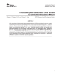
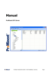
Open the Downloader application by double-clicking on the “Oztek Downloader” icon. The
following graphic depicts the main dialog window for the Downloader Utility. Note that only the
menu bar and the Browse button are enabled. Other components are enabled as the user
interacts with the application.
4.1
Specifying the Log File Directory
The Download Utility automatically saves a log file for each download session started. The user
can specify the log file directory by selecting the “File -> Log File Directory…” menu item.
4.2
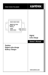
Selecting the Programmable File
The Browse button to the right of the Programmable File text box can be used to select a new
code image to download. Pressing this button will open the Select Target window, shown
below.
Publication UM-0015
3
4
Using the Downloader Utility
Note that Oztek control boards may have up to three different programmable devices whose
images are defined as follows:
DSP FLASH: This image is the controller’s runtime application and is stored in the
internal FLASH memory of the DSP on the control board.
Valid File Type: Code Composer Linker Generated COFF output file (*.out).
Bootloader EEPROM: This image contains the routines necessary to connect with the
Downloader Utility and is responsible for programming the selected device. Care must
be taken when selecting the EEPROM Boot Image for programming since future
programming of the FLASH and Boot EEPROM images will not work if a non-EEPROM
Boot image is selected.
Valid File Type: Code Composer Linker Generated COFF output file (*.out).
Data EEPROM: This image can be used for different purposes depending on the
application code running on the DSP. As such, this download type is optional and may
not be supported by some applications. This is typically not an executable image, but
rather user or application data that gets stored in an external EEPROM device.
Valid File Type: Motorola S-record formatted HEX file (*.hex).
Selecting the type of image and pressing “OK” will open a file dialog window. At this point the
user will navigate to the appropriate location and select the desired programming file.
4.3
Connecting to the Target
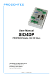
To search for an attached target control board, the user must use the “Connection” menu item.
If using CAN, select the appropriate CAN adapter from the “Connection -> CAN -> Connect”
menu item as shown in the figure below. Note that the “Enable Legacy CAN I/F” menu item is
typically only used to support older legacy Oztek controllers and should be left unchecked by
default.
Firmware Downloader Utility User’s Manual
Using the Downloader Utility
Similarly, if using a serial interface, select the appropriate COM port using the “Connection ->
Serial Port -> Connect” menu item. Note that the serial interface uses the Modbus serial
protocol for communicating with the target controller. By default, the Downloader utility uses a
target slave address of “2” when attempting to connect to the controller as this is the default
Modbus slave address for most Oztek controllers. For some applications, it is possible for the
user to change the slave address to a value other than “2” – in this case, the user must select
the correct slave address using the “Connection -> Serial Port -> Slave Address” drop down list.
Once the desired communication interface has been selected, the status bar at the bottom of
the window will briefly show an “Initializing CAN/Serial Device” message. If initialization is
successful, the next message shown in the status bar will be “Searching for Target,” at which
point the user can apply power to the control board. If the Downloader fails to initialize the
selected CAN or Serial adapter, the user should double check their USB connections (if
applicable) and click the “Refresh List” menu item under either the CAN or Serial Port menus to
rediscover the attached CAN or Serial devices.
Note: Many Oztek control boards require a hardware jumper to
enable the Bootloader. Refer to the User’s Manual for your
specific control board for details on proper installation of any
required jumpers. Failure to do so may prevent the Downloader
Utility from connecting to your target control board.
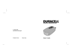
The following graphic indicates a successful connection with a target controller just after it has
been powered up. In this case, the target is a standard Oztek OZDSP3000 control board with
the Serial Bootloader image installed.
Publication UM-0015
5
6
Using the Downloader Utility
Once connected, the revision of the Bootloader code running on the control board is displayed
in the status bar. The Downloader Utility has now created a communications link with the
Bootloader through which a programmable image may now be transferred to the control board
target.
4.4
Download To Target Button
After a connection to the Bootloader has been made, the “Download to Target” button will be
enabled. Pressing this button will initiate the download process for the file specified in the
“Programmable File” text box.
If the user is attempting to reprogram the Bootloader EEPROM, the following message box will
be displayed:
Depending on the size of the programmable image, the download time could take a minute or
longer to complete. The following images illustrate the download process during the actions of
clearing memory, programming, and successful completion.
Firmware Downloader Utility User’s Manual
Using the Downloader Utility
Once the download is complete, the Downloader Utility remains connected to the target. At
this point the user may download another image, or press the “Jump to Flash” button to start
executing the application stored in FLASH memory. Closing the GUI does not cause the control
board to automatically jump to FLASH – the user must either use the “Jump to Flash” button or
cycle power on the control board in order to start executing the FLASH image.
If an error is detected during programming, the Downloader Utility will automatically initiate a
Clear Memory command to wipe the target of any partial image. The user should take special
care if this happens while updating the Bootloader itself as it may be possible that the
Bootloader is no longer programmed into the EEPROM. The user should NOT cycle power to the
control board until a successful programming attempt has been completed.
Publication UM-0015
7
8
Using the Downloader Utility
Warning: Should the Bootloader become corrupt for any reason,
or if the control board has not been previously loaded with the
Bootloader, please refer to Appendix A for the procedure to
program the initial Bootloader image.
4.5
Jump to Flash Button
After a connection to the Bootloader has been made, the “Jump to Flash” button is enabled.
This button can be used either to forego a programming operation or to disconnect once the
intended programming has completed. Pressing this button causes the Downloader Utility to
attempt to disconnect from the Bootloader. At this point the Bootloader check if a valid FLASH
application image is available and if so, it will start executing this application and the
Downloader will show that it is now disconnected. If a valid FLASH image is not available, an
error message will be displayed and the Downloader Utility will remain connected to the
Bootloader as shown in the images below.
4.6
Enabling Support for Legacy Bootloaders
The downloader utility provides support for boards that contain older Oztek Bootloaders. This
feature must be enabled by clicking the “Connection -> CAN -> Enable Legacy CAN I/F” menu
item while disconnected from the CAN USB interface as shown below.
Firmware Downloader Utility User’s Manual
Using the Downloader Utility
Note that this mode will only work when connected to the legacy Bootloader targets as the
CAN message identifiers and baud rate are different and incompatible with the standard Oztek
Bootloader. When operating in this mode, only DSP FLASH images may be updated; the option
to update the Bootloader or data EEPROM images is not available. Similarly, the “Jump to
Flash” option is also not supported on the older Bootloader targets; the user must cycle the
target’s power in order to start executing the newly programmed FLASH image.
4.7
Changing Serial Bit Rate
The embedded Bootloader images are initially configured to run their communications
interface at a specific bit rate following a power on reset (POR). For CAN-based Bootloaders,
the default CAN bit rate is 250kbps. For Serial-based Bootloaders, the default baud rate is
19200. The Bootloader and Downloader Utility applications support changing the serial bit rate
after a connection has been established. To do so, the user can use the “Connection -> CAN ->
Bit Rate” or “Connection -> Serial Port -> Baud Rate” menu items. Note that these menus are
disabled when first launching the Downloader Utility as it expects to connect to the Target at
the default rate following a POR of the target controller. The appropriate bit rate menu will
become enabled once a connection has been made to the target controller.
Note that for small to average sized programming files, the download time does not decrease
significantly when increasing the serial bit rate. The user must also keep in mind the physical
communications connections in their system as not all systems may be capable of downloading
at the maximum bit listed in the Downloader Utility. For this reason it is recommended that the
user not change the serial bit rate unless they are attempting to program very large images and
where the download time can be significantly decreased by using the faster bit rate.
Once the bit rate has been changed, the Downloader and Bootloader will continue to
communicate at the new rate for all subsequent Downloader operations. Note that the
Bootloader will remain at this bit rate until either a) changed by the user using the Downloader
or b) by cycling the power on the control board. Recall that when first opening the Downloader
Utility, it will always attempt to connect at the default bit rate, so it may be necessary to cycle
Publication UM-0015
9
10
Troubleshooting and Error Messages
power on the control board in the event that the Bootloader has been left running at a
different bit rate than the default value.
5.
Troubleshooting and Error Messages
If for any reason an error is encountered during initialization of the CAN or Serial converter or
when downloading the selected image, the user will be notified via the Downloader Utility’s
status bar at the bottom of the window and/or through a Message Box. The following error
messages will be displayed if problems are encountered during the application’s operation.
5.1
USB to CAN or Serial Error Messages
Table 2 - Troubleshooting USB to CAN or Serial Error Messages
Error Message
“No device detected”
“Get Info Failed”
“Send failed”
“Receive Failed”
5.2
Troubleshooting steps
1. Check that the CAN or Serial device drivers are installed
and working properly.
2. Check the cable connections between the CAN/Serial
device, the PC, and the control board.
3. Try closing and restarting the Downloader Utility.
File Errors
Table 3 - Troubleshooting File Error Messages
Error Message
“Cannot Open File”
“Cannot Read from File”
“Cannot Write to File”
“End of File Detected”
“Invalid File Extension”
“Unknown S-record type”
Troubleshooting steps
Verify that the selected “Programmable File” exists.
Verify the integrity of the selected “Programmable File”.
Verify that the selected log file directory is not set to read only.
Verify that the selected “Programmable File” is of the correct
type.
Verify the type of selected “Programmable File” as follows:
*.out file if the selected target is “DSP Flash” or
“Bootloader EEPROM”
*.hex file if the selected target is “Data EEPROM”
If a *.hex file is selected for a Data EEPROM target, it must be
in the Motorola S-record format.
Firmware Downloader Utility User’s Manual
Maintenance and Upgrade
5.3
Programming Errors
Table 4 - Troubleshooting Programming Error Messages
Error Message
“Illegal Target Type”
“CCP Error: Unknown command returned.”
“CCP Error: Invalid command syntax.”
“CCP Error: Parameter Out of Range.”
“CCP Access Denied.”
“CCP Error: Resource or Function
unavailable.”
“CCP Error: Operation Failure.”
6.
Troubleshooting steps
Verify that the control board supports the
selected target. Not all Oztek Control boards
support all of the available targets.
These are low level, CAN CCP protocol errors.
Take the following steps:
1. Verify that the correct order was
followed when connecting to the target,
i.e. the Downloader must be started and
the “Connect” command selected
BEFORE applying power to the control
board.
2. Verify that the Downloader is attached
to the Bootloader.
Maintenance and Upgrade
Please check the Oztek website (www.oztekcorp.com) for updates to the CAN Downloader
Utility.
Publication UM-0015
11
12
APPENDIX A – Initial Bootloader Programming Procedure
7.
APPENDIX A – Initial Bootloader Programming Procedure
This appendix describes how to load the Bootloader image into the EEPROM for the very first
time (or after the image has been corrupted following a failed update attempt). Because newly
installed EEPROM devices are blank, the Bootloader image will need to be manually loaded into
the DSPs RAM memory in order to then program the Bootloader itself into the EEPROM.
It is assumed that the user has sufficient experience with the Code Composer IDE from Texas
Instruments to navigate the menus and to start-up the application. This is the only software
tool needed for this process. Users who do not have access to Code Composer Studio and a
valid JTAG emulation adapter or who are unfamiliar with the DSP programming procedure
should consult Oztek for additional support.
7.1
Hardware Requirements
7.2
Software Requirements
7.3
See Section 2 (System Requirements)
JTAG emulator pods are used to connect the PC to the DSP on the target board.
There are several models available from vendors such as Signum Systems
(www.signum.com) and Spectrum Digital (www.spectrumdigital.com).
Code Composer Integrated Development Environment (IDE), version 3.3 or greater.
See www.ti.com for ordering information.
Bootloader file image. The file will be called SW*****_rev#_#.out where ***** will
be the software part number for the specific Oztek Bootloader image required, and
rev#_# represents the most current revision, for example: rev2_0.
Programming Procedure
Launch the Code Composer IDE and connect to the control board. Reset the CPU using the
“Debug >> Reset CPU” menu item as shown in the screenshot below. A window may popup on
the Code Composer application screen, but this can be ignored.
Firmware Downloader Utility User’s Manual
APPENDIX A – Initial Bootloader Programming Procedure
Next, load the Bootloader application itself using the “File>>Load Program” menu item as
shown in the screenshot below.
Publication UM-0015
13
14
APPENDIX A – Initial Bootloader Programming Procedure
After clicking on “File >> Load Program” you will be prompted to select the program code you
wish to load into the DSP. Navigate to where SW*****_rev#_#.out was placed on the PC and
highlight the .out file. After selecting the file, click the “Open” button. This will load it into
memory and make it ready for execution.
Before proceeding any further, you must now launch the Downloader Utility as described in
section 4 (Using the Downloader Utility). Ignore all instructions warning you to make sure the
control board is powered off….leave the control board powered on in this case. When you
reach the step instructing you to “apply power to the control board” perform the last remaining
step below.
Start the Bootloader program executing by selecting the “Debug >> Run” menu item as shown
in the screenshot below. The Bootloader code is now running and operating just as it would if it
had been automatically loaded from the EEPROM when first powering up.
At this point the Bootloader should be communicating with the Downloader Utility. Be sure to
download the Bootloader image into the “Bootloader EEPROM” target during this session so
that the use of Code Composer and the JTAG emulator will not be necessary for subsequent
downloads!
Firmware Downloader Utility User’s Manual
Warranty and Return
Warranty and Product Information
Limited Warranty
What does this warranty cover and how long does it last? This Limited Warranty is provided by Oztek Corp.
("Oztek") and covers defects in workmanship and materials in your OZSCR1000 controller. This Warranty Period
lasts for 18 months from the date of purchase at the point of sale to you, the original end user customer, unless
otherwise agreed in writing. You will be required to demonstrate proof of purchase to make warranty claims. This
Limited Warranty is transferable to subsequent owners but only for the unexpired portion of the Warranty Period.
Subsequent owners also require original proof of purchase as described in "What proof of purchase is required?"
What will Oztek do? During the Warranty Period Oztek will, at its option, repair the product (if economically
feasible) or replace the defective product free of charge, provided that you notify Oztek of the product defect
within the Warranty Period, and provided that through inspection Oztek establishes the existence of such a defect
and that it is covered by this Limited Warranty.
Oztek will, at its option, use new and/or reconditioned parts in performing warranty repair and building
replacement products. Oztek reserves the right to use parts or products of original or improved design in the repair
or replacement. If Oztek repairs or replaces a product, its warranty continues for the remaining portion of the
original Warranty Period or 90 days from the date of the return shipment to the customer, whichever is greater. All
replaced products and all parts removed from repaired products become the property of Oztek.
Oztek covers both parts and labor necessary to repair the product, and return shipment to the customer via an
Oztek-selected non-expedited surface freight within the contiguous United States and Canada. Alaska, Hawaii and
locations outside of the United States and Canada are excluded. Contact Oztek Customer Service for details on
freight policy for return shipments from excluded areas.
How do you get service? If your product requires troubleshooting or warranty service, contact your merchant. If
you are unable to contact your merchant, or the merchant is unable to provide service, contact Oztek directly at:
USA
Telephone: 603-546-0090
Fax: 603-386-6366
Email techsupport@oztekcorp.com
Direct returns may be performed according to the Oztek Return Material Authorization Policy described in your
product manual.
What proof of purchase is required? In any warranty claim, dated proof of purchase must accompany the
product and the product must not have been disassembled or modified without prior written authorization by
Oztek. Proof of purchase may be in any one of the following forms:
• The dated purchase receipt from the original purchase of the product at point of sale to the end user
• The dated dealer invoice or purchase receipt showing original equipment manufacturer (OEM) status
• The dated invoice or purchase receipt showing the product exchanged under warranty
Publication UM-0015
15
16
Warranty and Return
What does this warranty not cover? Claims are limited to repair and replacement, or if in Oztek's discretion
that is not possible, reimbursement up to the purchase price paid for the product. Oztek will be liable to you only
for direct damages suffered by you and only up to a maximum amount equal to the purchase price of the product.
This Limited Warranty does not warrant uninterrupted or error-free operation of the product or cover normal
wear and tear of the product or costs related to the removal, installation, or troubleshooting of the customer's
electrical systems. This warranty does not apply to and Oztek will not be responsible for any defect in or damage
to:
a) The product if it has been misused, neglected, improperly installed, physically damaged or altered,
either internally or externally, or damaged from improper use or use in an unsuitable environment
b) The product if it has been subjected to fire, water, generalized corrosion, biological infestations, or
input voltage that creates operating conditions beyond the maximum or minimum limits listed in the
Oztek product specifications including high input voltage from generators and lightning strikes
c) The product if repairs have been done to it other than by Oztek or its authorized service centers
(hereafter "ASCs")
d) The product if it is used as a component part of a product expressly warranted by another
manufacturer
e) The product if its original identification (trade-mark, serial number) markings have been defaced,
altered, or removed
f) The product if it is located outside of the country where it was purchased
g) Any consequential losses that are attributable to the product losing power whether by product
malfunction, installation error or misuse.
Disclaimer
Product
THIS LIMITED WARRANTY IS THE SOLE AND EXCLUSIVE WARRANTY PROVIDED BY OZTEK IN CONNECTION WITH YOUR OZTEK PRODUCT AND IS,
WHERE PERMITTED BY LAW, IN LIEU OF ALL OTHER WARRANTIES, CONDITIONS, GUARANTEES, REPRESENTATIONS, OBLIGATIONS AND
LIABILITIES, EXPRESS OR IMPLIED, STATUTORY OR OTHERWISE IN CONNECTION WITH THE PRODUCT, HOWEVER ARISING (WHETHER BY
CONTRACT, TORT, NEGLIGENCE, PRINCIPLES OF MANUFACTURER'S LIABILITY, OPERATION OF LAW, CONDUCT, STATEMENT OR OTHERWISE),
INCLUDING WITHOUT RESTRICTION ANY IMPLIED WARRANTY OR CONDITION OF QUALITY, MERCHANTABILITY OR FITNESS FOR A PARTICULAR
PURPOSE. ANY IMPLIED WARRANTY OF MERCHANTABILITY OR FITNESS FOR A PARTICULAR PURPOSE TO THE EXTENT REQUIRED UNDER
APPLICABLE LAW TO APPLY TO THE PRODUCT SHALL BE LIMITED IN DURATION TO THE PERIOD STIPULATED UNDER THIS LIMITED WARRANTY.
IN NO EVENT WILL OZTEK BE LIABLE FOR: (a) ANY SPECIAL, INDIRECT, INCIDENTAL OR CONSEQUENTIAL DAMAGES, INCLUDING LOST PROFITS,
LOST REVENUES, FAILURE TO REALIZE EXPECTED SAVINGS, OR OTHER COMMERCIAL OR ECONOMIC LOSSES OF ANY KIND, EVEN IF OZTEK HAS
BEEN ADVISED, OR HAD REASON TO KNOW, OF THE POSSIBILITY OF SUCH DAMAGE, (b) ANY LIABILITY ARISING IN TORT, WHETHER OR NOT
ARISING OUT OF OZTEK'S NEGLIGENCE, AND ALL LOSSES OR DAMAGES TO ANY PROPERTY OR FOR ANY PERSONAL INJURY OR ECONOMIC LOSS
OR DAMAGE CAUSED BY THE CONNECTION OF A PRODUCT TO ANY OTHER DEVICE OR SYSTEM, AND (c) ANY DAMAGE OR INJURY ARISING
FROM OR AS A RESULT OF MISUSE OR ABUSE, OR THE INCORRECT INSTALLATION, INTEGRATION OR OPERATION OF THE PRODUCT. IF YOU ARE
A CONSUMER (RATHER THAN A PURCHASER OF THE PRODUCT IN THE COURSE OF A BUSINESS) AND PURCHASED THE PRODUCT IN A MEMBER
STATE OF THE EUROPEAN UNION, THIS LIMITED WARRANTY SHALL BE SUBJECT TO YOUR STATUTORY RIGHTS AS A CONSUMER UNDER THE
EUROPEAN UNION PRODUCT WARRANTY DIRECTIVE 1999/44/EC AND AS SUCH DIRECTIVE HAS BEEN IMPLEMENTED IN THE EUROPEAN UNION
MEMBER STATE WHERE YOU PURCHASED THE PRODUCT. FURTHER, WHILE THIS LIMITED WARRANTY GIVES YOU SPECIFIC LEGAL RIGHTS, YOU
MAY HAVE OTHER RIGHTS WHICH MAY VARY FROM EU MEMBER STATE TO EU MEMBER STATE OR, IF YOU DID NOT PURCHASE THE PRODUCT
IN AN EU MEMBER STATE, IN THE COUNTRY YOU PURCHASED THE PRODUCT WHICH MAY VARY FROM COUNTRY TO COUNTRY AND
JURISDICTION TO JURISDICTION.
Firmware Downloader Utility User’s Manual
Warranty and Return
Return Material Authorization Policy
Before returning a product directly to Oztek you must obtain a Return Material Authorization (RMA) number and
the correct factory "Ship To" address. Products must also be shipped prepaid. Product shipments will be refused
and returned at your expense if they are unauthorized, returned without an RMA number clearly marked on the
outside of the shipping box, if they are shipped collect, or if they are shipped to the wrong location.
When you contact Oztek to obtain service, please have your instruction manual ready for reference and be
prepared to supply:
• The serial number of your product
• Information about the installation and use of the unit
• Information about the failure and/or reason for the return
• A copy of your dated proof of purchase
Return Procedure
Package the unit safely, preferably using the original box and packing materials. Please ensure that your product is
shipped fully insured in the original packaging or equivalent. This warranty will not apply where the product is
damaged due to improper packaging. Include the following:
• The RMA number supplied by Oztek clearly marked on the outside of the box.
• A return address where the unit can be shipped. Post office boxes are not acceptable.
• A contact telephone number where you can be reached during work hours.
• A brief description of the problem.
Ship the unit prepaid to the address provided by your Oztek customer service representative.
If you are returning a product from outside of the USA or Canada - In addition to the above, you MUST
include return freight funds and you are fully responsible for all documents, duties, tariffs, and deposits.
Out of Warranty Service
If the warranty period for your product has expired, if the unit was damaged by misuse or incorrect installation, if
other conditions of the warranty have not been met, or if no dated proof of purchase is available, your unit may be
serviced or replaced for a flat fee. If a unit cannot be serviced due to damage beyond salvation or because the
repair is not economically feasible, a labor fee may still be incurred for the time spent making this determination.
To return your product for out of warranty service, contact Oztek Customer Service for a Return Material
Authorization (RMA) number and follow the other steps outlined in "Return Procedure".
Payment options such as credit card or money order will be explained by the Customer Service Representative. In
cases where the minimum flat fee does not apply, as with incomplete units or units with excessive damage, an
additional fee will be charged. If applicable, you will be contacted by Customer Service once your unit has been
received.
Publication UM-0015
17