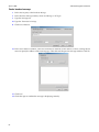
1
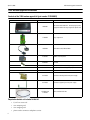
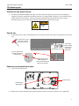
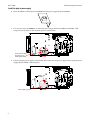
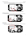
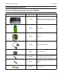
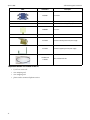
120V and 230V Modem
Upgrade Instructions
for AlphaEclipse StreetSmart Signs
Introduction
This document explains how to install a 120V or 230V modem into the following AlphaEclipse StreetSmart
signs: 17X, 35M, 35V and 35X
•
For 120V modems, see page 2.
•
For 230V modems, see page 11.
Safety
Disconnect main
power before
servicing!
Revision history
Part #
Date
1179659501
April 17, 2006
Notes
First release.
Related documentation
Part #
Title
1179600101
AlphaEclipse StreetSmart Installation Manual
9708-8081G
AlphaNET User Manual
© Copyright 2006 Adaptive Micro Systems LLC. All rights reserved.
Adaptive Micro Systems • 7840 North 86th Street • Milwaukee, WI 53224 USA • 414-357-2020 • 414-357-2029 (fax) • http://www.adaptivedisplays.com
Trademarked names appear throughout this document. Rather than list the names and entities that own the trademarks or insert a trademark symbol with each mention of the trademarked
name, the publisher states that it is using names for editorial purposes and to the benefit of the trademark owner with no intention of improperly using the trademark.
The following are trademarks of Adaptive Micro Systems: Adaptive, Alpha, AlphaLert, AlphaNET, AlphaNet plus, AlphaEclipse, AlphaPremiere, AlphaTicker, AlphaVision, AlphaVision
InfoTracker, AlphaXpress, Automode, BetaBrite, BetaBrite Director, BetaBrite Messaging Software, Big Dot, Director, EZ KEY II, EZ95, PagerNET, PPD, PrintPak, Serial Clock, Smart Alec,
Solar, TimeNet
The distinctive trade dress of this product is a trademark claimed by Adaptive Micro Systems LLC.
Due to continuing product innovation, specifications in this manual are subject to change without notice.
April 17, 2006
1179659501
April 17, 2006
120V modem upgrade instructions
120V modem upgrade instructions
Contents of the 120V modem upgrade kit (part number 1179200801)
Photo
Part number
Description
10889301
56k modem and modem kit - includes plug-in power
supply and modem-to-surge-suppressor phone cord.
11709022
Surge suppressor
10889205
Null modem cable, DB9 to DB25
43100303
NEMA 1-15R receptacle
43204023
Terminal
61213006
Screw, black, 10-24 x .375” (quantity 1)
61400003LF
65060004 and 65060005
2
•
5/32” hex screw tool
•
wire crimping tool
•
wire stripping tool
•
phone cord to connect to telephone service
Velcro
68116039
Aluminum mounting bracket for power supply
68116038
Aluminum supporting arm for power supply
71160190 and
71160193
Required materials not included in this kit
Screw, zinc, 6-32 x 1/4” (quantity 2)
White and black bulk wire
120V modem upgrade instructions
April 17, 2006
120V modem upgrade
Disconnect the main power to the sign
1.
Disconnect the MAIN POWER to the sign. You must disconnect the main power before installing this
upgrade. The power supply for the modem connects to a terminal block “upstream” of the internal power
switch. Unless the main power is disconnected, this terminal block will contain hazardous voltage.
DO NOT remove power to the sign by turning off the power switch inside the sign.
Disconnect main
power before
servicing!
Open the sign
2.
Loosen the four hex screws (circled below) on the controller section of the sign. Then pull the door toward
you.
Use a 5/32-inch hex screw
tool (pn 6811-7076) to
loosen the hex screws.
The controller
section is located
in bottom right
corner of the
bottom row.
There are 4 locks on the
sign door. Each lock is a
hexagon shape.
Do NOT remove any of the
Phillips head screws.
These screws hold the LED
boards to the sign door.
Remove the current communication option
3.
Locate the controller panel.
Controller panel
Communication
option location
4.
Remove the current communication option (modem, wireless transceiver, ethernet, etc.) if applicable.
3
April 17, 2006
120V modem upgrade instructions
Install the plug-in power supply
5.
Insert the NEMA 1-15R receptacle (43100303) into the power supply bracket (68116039).
6.
Use two zinc screws (61400003LF) to install the power supply bracket (68116039) with NEMA 1-15R
receptacle, into the holes on the controller panel as shown below:
Insert screws through
these holes in the
power supply bracket.
7.
Place the plug-in power supply, included with the modem, into the power supply bracket. Plug the power
supply into the NEMA 1-15R receptacle.
NEMA 1-15R
receptacle
Power supply
4
120V modem upgrade instructions
8.
April 17, 2006
Place the securing arm (68116038) under the plug-in power supply and use the black screw (61213006) to
attach the securing arm to the power supply bracket.
Insert the black screw here to attach the
securing arm to the mounting bracket.
Install the surge suppressor
9.
Using the screws included with the surge suppressor, attach the surge suppressor to the controller panel.
Install the modem
10. Apply the Velcro (65060004 and 65060005) to the back of the modem. Remove the protective backing from
the other side of the Velcro. Press the modem into place, as shown below.
5
April 17, 2006
120V modem upgrade instructions
Connect the wires and cables
11. Strip 1/4” from one end of the black and one end of the white wires. Crimp a terminal (43204023) to the
stripped end of each wire.
Crimp a terminal
to one end.
12. Attach the terminal end of the wires to the NEMA 1-15R receptacle. Attach the white wire to the silver
contact. Attach the black wire to the brass contact.
13. Route the black and white wires up and to the right of the modem as shown. Then, route the wires to the
left, above the fan to the terminal block.
14. Cut the wires to length, long enough to reach the terminal block. Strip 3/8” from the end of each wire.
15. Loosen the screw on the left side of the terminal block holding the white wire. Remove the wire from the
terminal block. Twist this wire with the stripped end of the white wire from the NEMA 1-15R receptacle.
Insert the twisted pair into the terminal. Hold the wires in place and retighten the screw.
16. Loosen the screw on the left side of the terminal block holding the black wire. Remove the wire from the
terminal block. Twist this wire with the stripped end of the black wire from the NEMA 1-15R receptacle.
Insert the twisted pair into the terminal. Hold the wires in place and retighten the screw.
White wire from
NEMA 1-15R
receptacle
Black wire from
NEMA 1-15R receptacle
S
Twist the pairs and re-insert
into the terminals.
6
Route the wires above the fan
to the terminal block.
120V modem upgrade instructions
April 17, 2006
17. Plug one end of the phone cord, included with the modem, into the RJ11 receptacle located on the top side
of the surge suppressor. Plug the other end into the RJ11 receptacle located on the bottom left of the
modem.
RJ11 receptacle
RJ11 receptacle
18. Plug the barrel-type connector from the power supply into the input power receptacle on the bottom right
side of the modem.
19. Plug the DB25 end of the null modem cable (10889205) into the modem. Plug the DB9 end into the
controller board as shown. Route the cable below the modem power supply.
Connect the DB25
end of the null
modem cable here
P7
Connect the DB9 end of
the null modem cable here
7
April 17, 2006
120V modem upgrade instructions
20. Connect the telephone service to the terminal block on the surge supressor.
To telephone service
RED
RING
GREEN
TIP
Red (RING)
Green (TIP)
}
Re-apply power to the sign
21. Close the sign door.
22. Re-apply power to the sign.
8
To
telephone
service
120V modem upgrade instructions
April 17, 2006
Test the installation
Before you begin
•
Install the sending modem into the messaging computer.
•
Know the com port to which the modem is connected.
Test the modem connection
1.
On the messaging computer, launch the AlphaNET Diagnostics software thru the Start menu
(Start>Programs>AlphaNET>Diagnostics).
2.
In the Communications pane of the Diagnostic window, select Modem.
3.
Click Setup to open the Transmitting Modem Setup window.
Select Modem
Click Setup
4.
Type the Number to Dial, including a 1 or 9, if applicable. Click OK.
Select Com Port to which
modem is connected
Type the Number to Dial
5.
In the Actions pane of the Diagnostics window, select Connect to Modem.
6.
When the modem connects, the bottom of the Actions pane will display Connected.
9
April 17, 2006
120V modem upgrade instructions
Send a broadcast message
7.
In the Actions pane, select Broadcast Message.
8.
In the Broadcast Message window, select Send Message to All Signs.
9.
Type the message text.
10. Type the Transmission Settings.
11. Click Select Addresses.
12. In the Select Addresses window, select Selected Addresses and then use the Address to Add to List drop-down
menu to specify the address of the receiving sign. Then click Add. Repeat for each sign address. Click OK.
13. Click Send.
14. Check the signs to confirm the message is displaying correctly.
.
10
230V modem upgrade instructions
April 17, 2006
230V modem upgrade instructions
Contents of the 230V modem upgrade kit (part number 1179200901)
Photo
Part number
Description
10889301
56k modem and modem kit - includes plug-in power
supply and modem-to-surge-suppressor phone cord.
11709022
Surge suppressor
40334601
Transformer
10889205
Null modem cable, DB9 to DB25
43100303
NEMA 1-15R receptacle
43204023
Small terminals - for connection with the NEMA 1-15R
receptacle and the transformer (quantity - 8)
43205003
Large terminal - for connection with the fuse holder
(quantity - 4)
48024001
Fuses (quantity - 2)
11
April 17, 2006
230V modem upgrade instructions
Photo
Part number
48034001
61213006
61400003LF
68000002
65060004 and 65060005
12
•
5/32” hex screw tool
•
wire crimping tool
•
wire stripping tool
•
phone cord to connect telephone service
Fuse Holder
Screw, black, 10-24 x .375” (quantity 1)
Screw, zinc, 6-32 x 1/4” (quantity 6)
Fuse cover
Velcro
68116039
Aluminum mounting bracket for power supply
68116038
Aluminum supporting arm for power supply
71160190 and
71160193
Required materials not included in this kit
Description
White and black bulk wire
230V modem upgrade instructions
April 17, 2006
230V modem upgrade
Disconnect the main power to the sign
1.
Disconnect the MAIN POWER to the sign. You must disconnect the main power before installing this
upgrade. The power supply for the modem connects to a terminal block “upstream” of the internal power
switch. Unless the main power is disconnected, this terminal block will contain hazardous voltage.
DO NOT remove power to the sign by turning off the power switch inside the sign.
Disconnect main
power before
servicing!
Open the sign
2.
Loosen the four hex screws (circled below) on the controller section of the sign. Then pull the door toward
you.
Use a 5/32-inch hex screw
tool (pn 6811-7076) to
loosen the hex screws.
The controller
section is located
in bottom right
corner of the
bottom row.
There are 4 locks on the
sign door. Each lock is a
hexagon shape.
Do NOT remove any of the
Phillips head screws.
These screws hold the LED
boards to the sign door.
Remove the current communications option
3.
Locate the controller panel.
Controller panel
Communication
option location
4.
Remove the current communication option (modem, wireless transceiver, ethernet, etc.) if applicable.
13
April 17, 2006
230V modem upgrade instructions
Install the power supply bracket
5.
Insert the NEMA 1-15R receptacle (43100303) into the power supply bracket (68116039).
6.
Use two zinc screws (61400003LF) to install the power supply bracket (68116039) with NEMA 1-15R
receptacle into the holes on the controller panel as shown below:
Insert screws through
these holes in the
power supply bracket.
Install the transformer
7.
14
Use two zinc screws (61400003LF) to install the transformer (40334601) as shown below.
230V modem upgrade instructions
April 17, 2006
Install the fuse holder and fuses
8.
Use the remaining two zinc screws (61400003LF) to install the fuse holder.
9.
Install the two fuses (48024001) in the fuse holder.
Connect the wires
NEMA 1-15R receptacle to transformer
10. Cut a 3.5” piece of wire from the bulk black and the white wires. Strip 1/4” from the end of each wire.
Crimp a small terminal (43204023) to both ends of each wire.
Crimp a small terminal
(43204023) to both
ends of each wire.
11. Attach one end of the white wire to the silver contact on the NEMA 1-15R receptacle. Attach the other end
of the wire to terminal 11 on the transformer.
12. Attach one end of the black wire to the brass contact on the NEMA 1-15R receptacle. Attach the other end
of the wire to terminal 12 on the transformer.
65
21
12 11
To NEMA 1-15R receptacle
15
April 17, 2006
230V modem upgrade instructions
Transformer terminals 2 and 5
13. Cut a 1.5” piece of wire from the bulk black wire. Strip 1/4” from both ends of the wire. Crimp a small
terminal (43204023) to both ends.
14. Attach one end of the 1.5” black wire to terminal 5 on the transformer. Attach the other end to terminal 2.
65
21
12 11
To NEMA 1-15R receptacle
Transformer to fuse holder
15. Cut a 3” piece of wire from the bulk white wire. Cut a 4” piece from the bulk black wire. Strip 1/4” from
both ends of each wire. Crimp a small terminal (43204023) to one end of each wire. Crimp a large terminal
(43205003) to the other end of each wire.
Crimp a large terminal
(43205003) to one
end of each wire.
Crimp a small terminal
(43204023) to one
end of each wire.
16. Attach the end of the white wire with the small terminal (43204023) to terminal 1 on the transformer.
Attach the other end, with the large terminal (43205003) to the lower left terminal on the fuse holder.
17. Attach the end of the black wire with the small terminal (43204023) to terminal 6 on the transformer.
Attach the other end, with the large terminal (43205003) to the upper left terminal on the fuse holder.
To left side of fuse holder.
65
21
12 11
To NEMA 1-15R receptacle
16
230V modem upgrade instructions
April 17, 2006
Fuse holder to terminal block
18. Strip 1/4” from one end of each of the remaining black and white wires. Crimp a large terminal (43205003)
to the stripped end of each wire.
19. Attach the terminal end of the white wire to the lower right terminal on the fuse holder.
20. Attach the terminal end of the black wire to the upper right terminal of the fuse holder.
21. Snap the fuse cover into place, over the fuses.
17
April 17, 2006
230V modem upgrade instructions
22. Route the black and white wires up and to left, above the fan to the terminal block.
23. Cut the wires to length, long enough to reach the terminal blocks. Strip 3/8” from the end of each wire.
24. Loosen the screw on the left side of the terminal block holding the white wire. Remove the white wire
from the terminal block. Twist this wire with the stripped end of the white wire from the fuse holder.
Insert the twisted pair into the terminal. Hold the wires in place and retighten the screw.
25. Loosen the screw on the left side of the terminal block holding the black wire. Remove the black wire from
the terminal block. Twist this wire with the stripped end of the black wire from the fuse holder. Insert the
twisted pair into the terminal. Hold the wires in place and retighten the screw.
White wire from
fuse holder
Route the wires above the fan
to the terminal block.
Black wire from
fuse holder
FUSE COVER
MUST BE IN
PLACE WHEN
UNIT IS
POWERED
S
Twist the pairs and re-insert
into the terminal.
Install the plug-in power supply
26. Place the plug-in power supply, included with the modem, into the power supply bracket. Plug the power
supply into the NEMA 1-15R receptacle.
NEMA 1-15R
receptacle
Power supply
18
230V modem upgrade instructions
April 17, 2006
27. Place the securing arm (68116038) under the plug-in power supply and use the black screw (61213006) to
attach the securing arm to the power supply bracket.
Insert the black screw here to attach the
securing arm to the mounting bracket.
Install the surge suppressor
28. Using the screws included with the surge suppressor, attach the surge suppressor to the controller panel.
19
April 17, 2006
230V modem upgrade instructions
Install the modem
29. Apply the Velcro (65060004 and 65060005) to the back of the modem. Remove the protective backing from
the other side of the Velcro. Press the modem into place, as shown below.
Connect the cables
30. Plug one end of the phone cord, included with the modem, into the RJ11 receptacle located on the top side
of the surge suppressor. Plug the other end into the RJ11 receptacle located on the bottom left of the
modem.
RJ11 receptacle
RJ11 receptacle
20
230V modem upgrade instructions
April 17, 2006
31. Plug the barrel-type connector from the power supply into the input power receptacle on the bottom right
side of the modem.
32. Plug the DB25 end of the null modem cable (10889205) into the modem. Plug the DB9 end of the null
modem cable into the controller board as shown. Route the cable below the modem power supply.
Connect the DB25
end of the null
modem cable here
P7
Connect the DB9 end of
the null modem cable here
21
April 17, 2006
230V modem upgrade instructions
33. Connect the telephone service to the terminal block on the surge supressor.
To telephone service
RED
RING
GREEN
TIP
Red (RING)
Green (TIP)
Re-apply power to the sign
34. Close the sign door.
35. Re-apply power to the sign.
22
}
To
telephone
service
230V modem upgrade instructions
April 17, 2006
Test the installation
Before you begin
•
Install the sending modem into the messaging computer.
•
Know the com port to which the modem is connected.
Test the modem connection
1.
On the messaging computer, launch the AlphaNET Diagnostics software thru the Start menu
(Start>Programs>AlphaNET>Diagnostics).
2.
In the Communications pane of the Diagnostic window, select Modem.
3.
Click Setup to open the Transmitting Modem Setup window.
Select Modem
Click Setup
4.
Type the Number to Dial, including a 1 or 9, if applicable. Click OK.
Select Com Port to which
modem is connected
Type the Number to Dial
5.
In the Actions pane of the Diagnostics window, select Connect to Modem.
6.
When the modem connects, the bottom of the Actions pane will display Connected.
23
April 17, 2006
230V modem upgrade instructions
Send a broadcast message
7.
In the Actions pane, select Broadcast Message.
8.
In the Broadcast Message window, select Send Message to All Signs.
9.
Type the message text.
10. Type the Transmission Settings.
11. Click Select Addresses.
12. In the Select Addresses window, select Selected Addresses and then use the Address to Add to List drop-down
menu to specify the address of the receiving sign. Then click Add. Repeat for each sign address. Click OK.
13. Click Send.
14. Check the signs to confirm the message is displaying correctly.
24