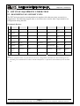
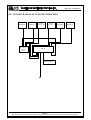
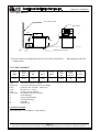
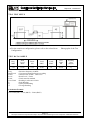
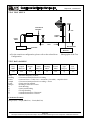
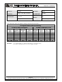
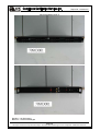
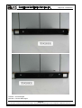
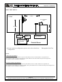
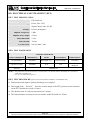
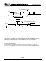
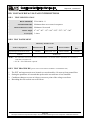
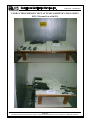
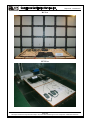
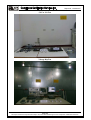
1
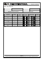
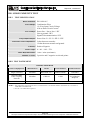
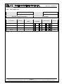
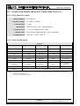
Report No.: 70903001-E CE EMC TEST REPORT for 4 ports / 8 ports Mobile Trunk MODEL: MT-358; MT-354; SC-855; SC-455 Test Report Number: 70903001-E Issued to: PORTech Communications Inc. 150, Shiang Shung North Road, Tai Chung, Taiwan 403 Issued by: Compliance Certification Services Inc. Sindian BU No.163-1, Jhongsheng Rd., Sindian City, Taipei County 23151, Taiwan TEL: 886-2-22170894 FAX: 886-2-22171029 Issued Date: September 12, 2007 Note: This report shall not be reproduced except in full, without the written approval of Compliance Certification Services Inc. This document may be altered or revised by Compliance Certification Services Inc. personnel only, and shall be noted in the revision section of the document. The client should not use it to claim product endorsement by TAF, A2LA, NVLAP, NIST or any government agencies. The test results in the report only apply to the tested sample. Page 1 / 69 Report No.: 70903001-E Revision History Rev. 00 Issue Date Revisions Initial Issue Effect Page ALL Revised By Page 2 This report shall not be reproduced except in full, without the written approval of Compliance Certification Services. Report No.: 70903001-E TABLE OF CONTENTS 1 2 3 4 4.1. 4.2. 5 5.1. 5.2. 6 6.1. 6.2. 6.3. 7 7.1. 7.2. 7.3. 7.4. 7.5. 8 8.1. 8.2. 8.3. 8.4. 8.5. 8.6. 8.7. 8.8. 8.9. 9 TEST CERTIFICATION .................................................................................................................4 TEST RESULT SUMMARY............................................................................................................5 EUT DESCRIPTION ........................................................................................................................6 TEST METHODOLOGY.................................................................................................................7 DECISION OF FINAL TEST MODE ................................................................................................7 EUT SYSTEM OPERATION.............................................................................................................7 SETUP OF EQUIPMENT UNDER TEST......................................................................................8 DESCRIPTION OF SUPPORT UNITS..............................................................................................8 CONFIGURATION OF SYSTEM UNDER TEST ............................................................................9 FACILITIES AND ACCREDITATIONS.....................................................................................10 FACILITIES......................................................................................................................................10 ACCREDITATIONS ........................................................................................................................10 MEASUREMENT UNCERTAINTY ...............................................................................................10 EMISSION TEST............................................................................................................................11 CONDUCTED EMISSION MEASUREMENT ...............................................................................11 CONDUCTED EMISSION MEASUREMENT AT TELECOMMUNICATION PORTS ..............15 RADIATED EMISSION MEASUREMENT ...................................................................................19 HARMONICS CURRENT MEASUREMENT ................................................................................25 VOLTAGE FLUCTUATION AND FLICKER MEASUREMENT.................................................28 IMMUNITY TEST..........................................................................................................................32 GENERAL DESCRIPTION .............................................................................................................32 GENERAL PERFORMANCE CRITERIA DESCRIPTION............................................................33 ELECTROSTATIC DISCHARGE (ESD) ........................................................................................34 RADIATED, RADIO-FREQUENCY, ELECTROMAGNETIC FIELD (RS) .................................41 ELECTRICAL FAST TRANSIENT (EFT) ......................................................................................45 SURGE IMMUNITY TEST..............................................................................................................48 CONDUCTED RADIO FREQUENCY DISTURBANCES (CS) ....................................................52 POWER FREQUENCY MAGNETIC FIELD..................................................................................56 VOLTAGE DIP & VOLTAGE INTERRUPTIONS.........................................................................59 PHOTOGRAPHS OF THE TEST CONFIGURATION .............................................................62 Page 3 This report shall not be reproduced except in full, without the written approval of Compliance Certification Services. Report No.: 70903001-E 1 TEST CERTIFICATION Product: 4 ports / 8 ports Mobile Trunk Model: MT-358; MT-354; SC-855; SC-455 Brand: PORTech; Suncomm Applicant: PORTech Communications Inc. 150, Shiang Shung North Road, Tai Chung, Taiwan 403 Manufacturer: PORTech Communications Inc. 150, Shiang Shung North Road, Tai Chung, Taiwan 403 Tested: September 4, 2007 ~ September 7, 2007 Applicable EN 55022: 2006, Class A Standards: EN 61000-3-2: 2000 EN 55024: 1998 + A1: 2001 IEC 61000-4-2: 1995 + A1: 1998 + A2: 2000 IEC 61000-4-3: 2002 + A1: 2002 IEC 61000-4-4: 2004 IEC 61000-4-5: 1995 + A1: 2000 IEC 61000-4-6: 1996 + A1: 2000 IEC 61000-4-8: 1993 + A1: 2000 IEC 61000-4-11: 2004 EN 61000-3-3: 1995 + A1: 2001 Deviation from Applicable Standard At the customers’ request, we adopt the above standards The above equipment has been tested by Compliance Certification Services Inc., and found compliance with the requirements set forth in the technical standards mentioned above. The results of testing in this report apply only to the product/system, which was tested. Other similar equipment will not necessarily produce the same results due to production tolerance and measurement uncertainties. Page 4 This report shall not be reproduced except in full, without the written approval of Compliance Certification Services. Report No.: 70903001-E 2 TEST RESULT SUMMARY EMISSION Item Result Conducted (Main Port) PASS Meet Class A limit Conducted (Telecom port) PASS Meet Class A limit Radiated PASS Meet Class A limit Harmonic current emissions N/A Please see the page 27 Voltage fluctuations & flicker PASS Meets the requirements Standard EN 55022: 2006 EN 61000-3-2 (2000) EN 61000-3-3 (1995) + A1 (2001) Remarks IMMUNITY【 EN 55024 (1998 + A1: 2001) 】 Standard Item Result ESD PASS Meets the requirements of Performance Criterion B IEC 61000-4-3: 2002 + A1: 2002 RS PASS Meets the requirements of Performance Criterion A IEC 61000-4-4: 2004 EFT PASS Meets the requirements of Performance Criterion B IEC 61000-4-5: 1995 + A1: 2000 Surge PASS Meets the requirements of Performance Criterion B IEC 61000-4-6: 1996 + A1: 2000 CS PASS Meets the requirements of Performance Criterion A IEC 61000-4-8:1993 + A1: 2000 PFMF N/A Please see the page 58 PASS Meets the requirements of Voltage Dips: 1) >95% reduction Performance Criterion B 2) 30% reduction Performance Criterion C Voltage Interruptions: 1) >95% reduction Performance Criterion C. IEC 61000-4-2: 1995 + A1: 1998 + A2: 2000 IEC 61000-4-11: 2004 Note: Voltage dips & voltage variations Remarks 1. The test result judgment is decided by the limit of test standard 2. The information of measurement uncertainty is available upon the customer’s request. Page 5 This report shall not be reproduced except in full, without the written approval of Compliance Certification Services. Report No.: 70903001-E 3 EUT DESCRIPTION Product 4 ports / 8 ports Mobile Trunk Brand Name PORTech; Suncomm Model MT-358; MT-354; SC-855; SC-455 Applicant PORTech Communications Inc. Housing material Metal case Serial Number N/A Received Date September 3, 2007 EUT Power Rating 110VAC~230VAC, 50Hz AC Power During Test 230VAC/50Hz AC Power Cord Type Unshielded, 1.8m (Detachable) Model Differences Original Additional Model Name MT-358 MT-354 SC-855 SC-455 Brand Name Difference Tested (Checked) PORTech Suncomm I/O PORT I/O PORT TYPES 1. 2. 3. PSTN Port Phone Port Antenna Port Q’TY TESTED WITH 8 8 2 8 8 2 Note: Client consigns only one model sample (Model Number is MT-358) to test. Page 6 This report shall not be reproduced except in full, without the written approval of Compliance Certification Services. Report No.: 70903001-E 4 TEST METHODOLOGY 4.1. DECISION OF FINAL TEST MODE The EUT was tested together with the above additional components, and a configuration, which produced the worst emission levels, was selected and recorded in this report. The test configuration/ mode is as the following: Mode: 1. Normal Mode Conduction: Mode 1 Radiation: Mode 1 4.2. EUT SYSTEM OPERATION 1. All peripherals connect EUT to test. 2. Let phone “101” calls to phone “103”, pick up the phone to connect each other. 3. Let phone “102” calls to phone “104”, pick up the phone to connect each other. Note: Test program is self-repeating throughout the test. Page 7 This report shall not be reproduced except in full, without the written approval of Compliance Certification Services. Report No.: 70903001-E 5 SETUP OF EQUIPMENT UNDER TEST 5.1. DESCRIPTION OF SUPPORT UNITS The EUT has been tested as an independent unit together with other necessary accessories or support units. The following support units or accessories were used to form a representative test configuration during the tests. Peripherals Devices: No. Equipment Model No. Serial No. FCC ID/ BSMI ID Trade Name Data Cable Power Cord 1 Telephone 475 N/A N/A KOKA Unshielded, 2.0 m N/A 2 Telephone 475 N/A N/A KOKA Unshielded, 2.0 m N/A 3 Antenna Collecting box N/A N/A N/A PORTech Unshielded, 3.0m N/A 4 Antenna Collecting box N/A N/A N/A PORTech Unshielded, 3.0m N/A 5 Telephone TP-318 N/A T90-T159-C KOKA Unshielded, 2.0m N/A 6 Telephone HTT-213 N/A N/A SHIN-KAN-SEN Unshielded, 2.0m N/A 7 Telephone Line Simulator (TLT-1) TLS-4A-01 042829 DoC TELTONE Unshielded, 2.0 mx2 Unshielded, 1.8m 8 RJ11 Load N/A N/A N/A N/A Unshielded, 2.0m x12 N/A Note: 1) All the equipment/cables were placed in the worst-case configuration to maximize the emission during the test. 2) Grounding was established in accordance with the manufacturer’s requirements and conditions for the intended use. Page 8 This report shall not be reproduced except in full, without the written approval of Compliance Certification Services. Report No.: 70903001-E 5.2. CONFIGURATION OF SYSTEM UNDER TEST Telephone Telephone Line Simulator (TLT-1) Telephone Antenna Collecting box Antenna Collecting box Telephone Telephone EUT RJ11 Load x12 Page 9 This report shall not be reproduced except in full, without the written approval of Compliance Certification Services. Report No.: 70903001-E 6 FACILITIES AND ACCREDITATIONS 6.1. FACILITIES All measurement facilities (except Harmonic/Flicker of EN 61000-3-2/-3) used to collect the measurement data are located at CCS Taiwan Sindian BU at No.163-1, Jhongsheng Rd., Sindian City, Taipei County 23151, Taiwan. The measurement facilities Harmonic/Flicker of EN 61000-3-2/-3 are located at CCS Wugu BU No.11, Wugong 6th Rd., Wugu Township, Taipei County 24891, Taiwan. The sites are constructed in conformance with the requirements of ANSI C63.4 and CISPR Publication 22. All receiving equipment conforms to CISPR 16-1-1, CISPR 16-1-2, CISPR 16-1-3, CISPR 16-1-4 and CISPR 16-1-5. 6.2. ACCREDITATIONS Our laboratories are accredited and approved by the following approval agencies according to ISO/IEC 17025. USA Germany Japan Norway Canada Taiwan FCC, A2LA TUV Rheinland VCCI NEMKO INDUSTRY CANADA TAF, BSMI Copies of granted accreditation certificates are available for downloading from our web site, http://www.ccsemc.com.tw 6.3. MEASUREMENT UNCERTAINTY Where relevant, the following measurement uncertainty levels have been estimated for tests performed on the EUT as specified in CISPR 16-4-2: Measurement Frequency Uncertainty Conducted emissions 9kHz~30MHz ± 1.7376 30MHz ~ 200MHz ± 3.8773 200MHz ~1000MHz ± 3.8820 Radiated emissions This uncertainty represents an expanded uncertainty expressed at approximately the 95% confidence level using a coverage factor of k=2. Page 10 This report shall not be reproduced except in full, without the written approval of Compliance Certification Services. Report No.: 70903001-E 7 EMISSION TEST 7.1. CONDUCTED EMISSION MEASUREMENT 7.1.1. LIMITS Class A (dBuV) FREQUENCY (MHz) Class B (dBuV) Quasi-peak Average Quasi-peak Average 0.15 - 0.5 79 66 66 - 56 56 - 46 0.50 - 5.0 73 60 56 46 5.0 - 30.0 73 60 60 50 NOTE: (1) The lower limit shall apply at the transition frequencies. (2) The limit decreases in line with the logarithm of the frequency in the range of 0.15 to 0.50 MHz. (3) All emanations from a class A/B digital device or system, including any network of conductors and apparatus connected thereto, shall not exceed the level of field strengths specified above. 7.1.2. TEST INSTRUMENTS Conducted Emission Room # A Name of Equipment Manufacturer Model Serial Number Calibration Due TEST RECEIVER R&S ESHS20 840455/006 02/12/2008 LISN (EUT) SCHWARZBECK NSLK 8127 8127382 12/06/2007 LISN SOLAR 8012-50-R-24-BNC 8305114 12/26/2007 BNC CABLE Huber+Suhner RG-223/U BNC A2 05/13/2008 THERMOHYGRO METER TOP HA-202 9303-1 02/04/2008 Test S/W EMI 32.exe NOTE: 1. The calibration interval of the above test instruments is 12 months and the calibrations are traceable to NML/ROC and NIST/USA. 2. N.C.R = No Calibration Request. Page 11 This report shall not be reproduced except in full, without the written approval of Compliance Certification Services. Report No.: 70903001-E 7.1.3. TEST PROCEDURES (please refer to measurement standard or CCS SOP PA-031) Procedure of Preliminary Test The EUT and Support equipment, if needed, was set up as per the test configuration to simulate typical usage per the user’s manual. When the EUT is a tabletop system, a wooden table with a height of 0.8 meters is used and is placed on the ground plane as per EN 55022 (see Test Facility for the dimensions of the ground plane used). When the EUT is a floor standing equipment, it is placed on the ground plane, which has a 3-12 mm non-conductive covering to insulate the EUT from the ground plane. All I/O cables were positioned to simulate typical actual usage as per EN 55022. The test equipment EUT installed received AC main power, through a Line Impedance Stabilization Network (LISN), which supplied power source and was grounded to the ground plane. All support equipment power received from a second LISN. The EUT test program was started. Emissions were measured on each current carrying line of the EUT using an EMI Test Receiver connected to the LISN powering the EUT. The Receiver scanned from 150kHz to 30MHz for emissions in each of the test modes. During the above scans, the emissions were maximized by cable manipulation. The test mode(s) described in Item 3.1 were scanned during the preliminary test. After the preliminary scan, we found the test mode described in Item 3.1 producing the highest emission level. The EUT configuration and cable configuration of the above highest emission levels were recorded for reference of the final test. Procedure of Final Test EUT and support equipment were set up on the test bench as per the configuration with highest emission level in the preliminary test. A scan was taken on both power lines, Line 1 and Line 2, recording at least the six highest emissions. Emission frequency and amplitude were recorded into a computer in which correction factors were used to calculate the emission level and compare reading to the applicable limit. The test data of the worst-case condition(s) was recorded. Page 12 This report shall not be reproduced except in full, without the written approval of Compliance Certification Services. Report No.: 70903001-E 7.1.4. TEST SETUP Vert. reference plane EMI receiver 40cm EUT 80cm LISN Reference ground plane For the actual test configuration, please refer to the related item – Photographs of the Test Configuration. 7.1.5. DATA SAMPLE Freq. MHz Read Level dBuV Factor dB Level dBuV Limit dBuV Over Limit dB Reading Type (P/Q/A) Line (L1/L2) x.xx 42.95 0.55 43.50 73 -29.50 Q L1 Freq. Read Level Factor Level Limit Over Limit P Q A L1 L2 = Emission frequency in MHz = Uncorrected Analyzer/Receiver reading = Insertion loss of LISN + Cable Loss = Read Level + Factor = Limit stated in standard = Reading in reference to limit = Peak Reading = Quasi-peak Reading = Average Reading = Hot side = Neutral side Calculation Formula Over Limit (dB) = Level (dBuV) – Limit (dBuV) Page 13 This report shall not be reproduced except in full, without the written approval of Compliance Certification Services. Report No.: 70903001-E 7.1.6. TEST RESULTS Model No. MT-358 6dB BANDWIDTH 10 KHz Environmental Conditions 26deg.C, 69% RH, 1011 hPa Test Mode Mode 1 Tested by Webber Chung (The chart below shows the highest readings taken from the final data.) Six Highest Conducted Emission Readings Frequency Range Investigated Read Freq Factor Level Level (MHz) (dB) (dBuV) (dBuV) 4.361 44.38 0.74 45.12 11.870 47.90 1.15 49.05 13.127 47.11 1.19 48.30 4.292 47.13 0.33 47.46 9.705 42.29 0.67 42.96 13.197 43.96 0.85 44.81 Limit Line (dBuV) 73.00 73.00 73.00 73.00 73.00 73.00 150 KHz to 30 MHz Over Reading Limit Type (dB) (P/Q/A) -27.88 P -23.95 P -24.70 P -25.54 P -30.04 P -28.19 P Line (L1/L2) L1 L1 L1 L2 L2 L2 NOTE: 1. The emission level was or more than 2dB below the Average limit, so no re-check anymore. 2. L1 = Line One (Live Line) / L2 = Line Two (Neutral Line) Page 14 This report shall not be reproduced except in full, without the written approval of Compliance Certification Services. Report No.: 70903001-E 7.2. CONDUCTED EMISSION MEASUREMENT AT TELECOMMUNICATION PORTS 7.2.1. LIMITS For Class A Equipment FREQUENCY (MHz) Voltage Limit (dBuV) Current Limit (dBuA) Quasi-peak Average Quasi-peak Average 0.15 ~ 0.5 97 ~ 87 84 ~ 74 53 ~ 43 40 ~ 30 0.5 ~ 30.0 87 74 43 30 NOTE: The limits decrease linearly with the logarithm of the frequency in the range 0.15 MHz to 0.5 MHz. For Class B Equipment FREQUENCY (MHz) Voltage Limit (dBuV) Current Limit (dBuA) Quasi-peak Average Quasi-peak Average 0.15 - 0.5 84 ~ 74 74 ~ 64 40 ~ 30 30 ~ 20 0.5 - 30.0 74 64 30 20 NOTE: 1. The limits decrease linearly with the logarithm of the frequency in the range 0,15 MHz to 0,5 MHz. Page 15 This report shall not be reproduced except in full, without the written approval of Compliance Certification Services. Report No.: 70903001-E 7.2.2. TEST INSTRUMENTS Conducted Emission Room # A Name of Equipment Manufacturer Model Serial Number Calibration Due TEST RECEIVER R&S ESHS20 840455/006 02/12/2008 LISN (EUT) SCHWARZBECK NSLK 8127 8127382 12/06/2007 LISN SOLAR 8012-50-R-24-BNC 8305114 12/26/2007 BNC CABLE Huber+Suhner RG-223/U BNC A2 05/13/2008 THERMOHYGRO METER TOP HA-202 9303-1 02/04/2008 4-Wire ISN R&S ENY41 100006 07/04/2008 2-Wire ISN R&S ENY22 100020 07/04/2008 Test S/W EMI 32.exe NOTE: 1. The calibration interval of the above test instruments is 12 months and the calibrations are traceable to NML/ROC and NIST/USA. 2. N.C.R = No Calibration Request. 7.2.3. TEST PROCEDURE (please refer to measurement standard or CCS SOP PA-031) Selecting ISN for unscreened cable or a current probe for screened cable to take measurement. The port of the EUT was connected to the remote side support equipment through the ISN/Current Probe and communication in normal condition. Making a overall range scan by using the test receiver controlled by controller and record at least six highest emissions for showing in the test report. Emission frequency and amplitude were recorded into a computer in which correction factors were used to calculate the emission level and compare reading to the applicable limit. In case of measuring on the screened cable, the current limit shall be applied; otherwise the voltage limit should be applied. The following test mode was scanned during the preliminary test: Mode(s): 1. 2. PSTN 1 Port PSTN 4 Port RJ11 Mode RJ11 Mode After the preliminary scan, we found the following test mode(s) producing the highest emission level and test data of the worst case was recorded. Mode: 2. Page 16 This report shall not be reproduced except in full, without the written approval of Compliance Certification Services. Report No.: 70903001-E 7.2.4. TEST SETUP For the actual test configuration, please refer to the related item – Photographs of the Test Configuration. 7.2.5. DATA SAMPLE Freq. MHz Read Level dBuV Factor dB Level dBuV Limit dBuV Over Limit dB Reading Type (P/Q/A) x.xx 62.95 0.55 63.50 87 -23.50 Q Freq. Read Level Factor Level Limit Over Limit P Q A = Emission frequency in MHz = Uncorrected Analyzer/Receiver reading = Insertion loss of ISN + Cable Loss = Read Level + Factor = Limit stated in standard = Reading in reference to limit = Peak Reading = Quasi-peak Reading = Average Reading Calculation Formula Over Limit (dB) = Level (dBuV) – Limit (dBuV) Page 17 This report shall not be reproduced except in full, without the written approval of Compliance Certification Services. Report No.: 70903001-E 7.2.6. TEST RESULTS Model No. MT-358 6dB BANDWIDTH 10 KHz Environmental Conditions 26deg.C, 69% RH, 1011 hPa Test Mode Mode 2 Tested by Webber Chung (The chart below shows the highest readings taken from the final data.) Six Highest Conducted Emission Readings Frequency Range Investigated Read Freq Factor Level (MHz) (dB) (dBuV) 4.315 39.94 10.32 4.549 41.95 10.33 5.031 50.51 10.33 5.277 50.09 10.34 5.623 41.78 10.34 12.516 42.83 10.48 Level (dBuV) 50.26 52.28 60.84 60.43 52.12 53.31 150 KHz to 30 MHz Limit Over Reading Line Limit Type (dBuV) (dB) (P/Q/A) 87.00 -36.74 P 87.00 -34.72 P 87.00 -26.16 P 87.00 -26.57 P 87.00 -34.88 P 87.00 -33.69 P NOTE: 1. The emission level was or more than 2dB below the Average limit, so no re-check anymore. Page 18 This report shall not be reproduced except in full, without the written approval of Compliance Certification Services. Report No.: 70903001-E 7.3. RADIATED EMISSION MEASUREMENT 7.3.1. LIMITS dBuV/m (At 10m) FREQUENCY (MHz) Class A Class B 30 ~ 230 40 30 230 ~ 1000 47 37 NOTE: (1) The lower limit shall apply at the transition frequencies. (2) Emission level (dBuV/m) = 20 log Emission level (uV/m). 7.3.2. TEST INSTRUMENTS Open Area Test Site # J Name of Equipment Manufacturer Model SITE NSA CCS J Site N/A 10/14/2007 MEASURE RECEIVER SCHAFFNER SCR3501 330 06/10/2008 SPECTRUM ANALYZER ADVANTEST R3132 120900003 No Calibration Required ANTENNA SCHAFFNER CBL 6112B 2800 09/23/2007 PREAMPLIFIER SCHAFFNER CPA9231A 3629 10/10/2007 CABLE BELDEN 9913 N-TYPE #J3 08/23/2008 ATTENUATOR MCL UNAT-6 AT06-8 12/03/2007 THERMOHYGRO METER TFA N/A NO.3 10/26/2007 Test S/W Serial Number Calibration Due LAB VIEW 5.1 NOTE: 1. The calibration interval of the above test instruments is 12 months and the calibrations are traceable to NML/ROC and NIST/USA. 2. N.C.R = No Calibration Request. Page 19 This report shall not be reproduced except in full, without the written approval of Compliance Certification Services. Report No.: 70903001-E 7.3.3. TEST PROCEDURE (please refer to measurement standard or CCS SOP PA-031) Procedure of Preliminary Test The equipment was set up as per the test configuration to simulate typical usage per the user’s manual. When the EUT is a tabletop system, a wooden turntable with a height of 0.8 meters is used which is placed on the ground plane. When the EUT is a floor standing equipment, it is placed on the ground plane which has a 3-12 mm non-conductive covering to insulate the EUT from the ground plane. Support equipment, if needed, was placed as per EN 55022. All I/O cables were positioned to simulate typical usage as per EN 55022. The EUT received AC power source from the outlet socket under the turntable. All support equipment power received from another socket under the turntable. The antenna was placed at 10 meter away from the EUT as stated in EN 55022. The antenna connected to the Spectrum Analyzer via a cable and at times a pre-amplifier would be used. The Analyzer / Receiver quickly scanned from 30MHz to 1000MHz. The EUT test program was started. Emissions were scanned and measured rotating the EUT to 360 degrees and positioning the antenna 1 to 4 meters above the ground plane, in both the vertical and the horizontal polarization, to maximize the emission reading level. The test mode(s) described in Item 3.1 were scanned during the preliminary test: After the preliminary scan, we found the test mode described in Item 3.1 producing the highest emission level. The EUT and cable configuration, antenna position, polarization and turntable position of the above highest emission level were recorded for the final test. Page 20 This report shall not be reproduced except in full, without the written approval of Compliance Certification Services. Report No.: 70903001-E Procedure of Final Test EUT and support equipment were set up on the turntable as per the configuration with highest emission level in the preliminary test. The Analyzer / Receiver scanned from 30MHz to 1000MHz. Emissions were scanned and measured rotating the EUT to 360 degrees, varying cable placement and positioning the antenna 1 to 4 meters above the ground plane, in both the vertical and the horizontal polarization, to maximize the emission reading level. Recorded at least the six highest emissions. Emission frequency, amplitude, antenna position, polarization and turntable position were recorded into a computer in which correction factors were used to calculate the emission level and compare reading to the applicable limit and only Q.P. reading is presented. The test data of the worst-case condition(s) was recorded. Page 21 This report shall not be reproduced except in full, without the written approval of Compliance Certification Services. Report No.: 70903001-E 7.3.4. TEST SETUP Test table & Turntable 1m ~ 4m EUT Coaxial Cable Power Cable 0.8 m 10 m Filter Filter Ground Plane To Power EMI Receiver For the actual test configuration, please refer to the related item – Photographs of the Test Configuration. 7.3.5. DATA SAMPLE Freq. MHz Amptd dBuV/m Margin dB Limit dBuV/m Reading dBuV Factor dB/m Reading Type (P/Q/A) Pol. (H/V) x.xx 26.2 -13.8 40 14 12.2 Q H Freq. Reading Factor Amptd Limit Margin P Q A H V = Emission frequency in MHz = Uncorrected Analyzer/Receiver reading = Antenna Factor + Cable Loss + Attenuator (3/6/10dB) – Amplifier Gain = Uncorrected Analyzer/Receiver reading + Factor = Limit stated in standard = Reading in reference to limit = Peak Reading = Quasi-peak Reading = Average Reading = Antenna Polarization: Horizontal = Antenna Polarization: Vertical Calculation Formula Margin (dB) = Amptd (dBuV/m) – Limit (dBuV/m) Page 22 This report shall not be reproduced except in full, without the written approval of Compliance Certification Services. Report No.: 70903001-E 7.3.6. TEST RESULTS Model No. MT-358 Test Mode Mode 1 Environmental Conditions 26deg.C, 84% RH, 1010 hPa 6dB BANDWIDTH 120 KHz Antenna Pole Vertical Antenna Distance 10m Detector Function Quasi-peak. Tested by Webber Chung (The chart below shows the highest readings taken from the final data.) Six Highest Radiated Emission Readings Frequency Range Investigated Freq. MHz 50.0000 109.0600 120.0100 154.8300 419.0900 848.8100 REMARKS: Amptd dBuV/m 28.27 29.62 27.34 29.99 33.76 35.56 Margin dB -11.73 -10.38 -12.66 -10.01 -13.24 -11.44 Limit dBuV/m 40.00 40.00 40.00 40.00 47.00 47.00 30 MHz to 1000 MHz at 10m Reading Pol. Reading Factor Type (H/V) dBuV dB/m (P/Q/A) 40.80 -12.53 Q V 39.80 -10.18 Q V 36.50 -9.16 Q V 40.20 -10.21 Q V 35.70 -1.94 Q V 30.90 4.66 Q V 1. P= Peak Reading; Q= Quasi-peak Reading A= Average Reading 2. The other emission levels were very low against the limit. Page 23 This report shall not be reproduced except in full, without the written approval of Compliance Certification Services. Report No.: 70903001-E Model No. MT-358 Test Mode Mode 1 Environmental Conditions 26deg.C, 84% RH, 1010 hPa 6dB BANDWIDTH 120 KHz Antenna Pole Horizontal Antenna Distance 10m Detector Function Quasi-peak. Tested by Webber Chung (The chart below shows the highest readings taken from the final data.) Six Highest Radiated Emission Readings Frequency Range Investigated Freq. MHz 120.0200 154.8400 210.1800 429.8500 627.2400 687.2400 REMARKS: Amptd dBuV/m 26.74 30.69 27.37 35.07 35.36 36.87 Margin dB -13.26 -9.31 -12.63 -11.93 -11.64 -10.13 Limit dBuV/m 40.00 40.00 40.00 47.00 47.00 47.00 30 MHz to 1000 MHz at 10m Reading Pol. Reading Factor Type (H/V) dBuV dB/m (P/Q/A) 35.90 -9.16 Q H 40.90 -10.21 Q H 38.00 -10.63 Q H 36.80 -1.73 Q H 32.90 2.46 Q H 33.90 2.97 Q H 1. P= Peak Reading; Q= Quasi-peak Reading A= Average Reading 2. The other emission levels were very low against the limit. Page 24 This report shall not be reproduced except in full, without the written approval of Compliance Certification Services. Report No.: 70903001-E 7.4. HARMONICS CURRENT MEASUREMENT 7.4.1. LIMITS OF HARMONICS CURRENT MEASUREMENT Limits for Class A equipment Harmonics Max. permissible Order harmonics current n A Odd harmonics 3 2.30 5 1.14 7 0.77 9 0.40 11 0.33 13 0.21 15<=n<=39 0.15x15/n Even harmonics 2 1.08 4 0.43 6 0.30 8<=n<=40 0.23x8/n Limits for Class D equipment Harmonics Order n Max. permissible harmonics current A Max. permissible harmonics current per watt mA/W Odd Harmonics only 3 5 7 9 11 13 15<=n<=39 3.4 1.9 1.0 0.5 0.35 0.30 3.85/n 2.30 1.14 0.77 0.40 0.33 0.21 0.15x15/n NOTE: 1. Class A and Class D are classified according to item 4.4.3. 2. According to section 7 of EN 61000-3-2, the above limits for all equipment except for lighting equipment having an active input power > 75 W and no limits apply for equipment with an active input power up to and including 75 W. 7.4.2. TEST INSTRUMENTS Name of Equipment Manufacturer Model Serial Number Calibration Due Harmonic & Flicker Tester EMC-PARTNER HARMONICS-1000 094 11/22/2007 Software Win2100V3.exe NOTE: 1. The calibration interval of the above test instruments is 12 months and the calibrations are traceable to NML/ROC and NIST/USA. Page 25 This report shall not be reproduced except in full, without the written approval of Compliance Certification Services. Report No.: 70903001-E 7.4.3. TEST PROCEDURE (please refer to measurement standard or CCS SOP PA-029) The EUT was placed on the top of a wooden table 0.8 meters above the ground and operated to produce the maximum harmonic components under normal operating conditions for each successive harmonic component in turn. The classification of EUT is according to section 5 of EN 61000-3-2. The EUT is classified as follows: Class A: Balanced three-phase equipment, Household appliances excluding equipment as Class D, Tools excluding portable tools, Dimmers for incandescent lamps, audio equipment, equipment not specified in one of the three other classes. Class B: Portable tools; Arc welding equipment which is not professional equipment. Class C: Lighting equipment. Class D: Equipment having a specified power less than or equal to 600 W of the following types: Personal computers and personal computer monitors and television receivers. The correspondent test program of test instrument to measure the current harmonics emanated from EUT is chosen. The measure time shall be not less than the time necessary for the EUT to be exercised. Page 26 This report shall not be reproduced except in full, without the written approval of Compliance Certification Services. Report No.: 70903001-E 7.4.4. TEST SETUP Harmonics & Flicker Analyzer + Power Source Power EUT Support Units 0.8m For the actual test configuration, please refer to the related item – Photographs of the Test Configuration. 7.4.5. TEST RESULTS Power Consumption 2.454W Test Results PASS Environmental Conditions N/A Limits Class Test Mode N/A Tested by N/A A B C D NOTE: 1. Limits classified according to item 7.4.3. 4. According to clause 7 of EN 61000-3-2: 2000, equipment with a rated power of 75W or less, no limits apply. The test result is only for reference. 3. Urms = 229.9V Irms = 0.024A P = 2.454W Freq = Ipk = S = 60.000 0.171A 5.613VA Range: cf = pf = 50 A 7.000 0.437 Page 27 This report shall not be reproduced except in full, without the written approval of Compliance Certification Services. Report No.: 70903001-E 7.5. VOLTAGE FLUCTUATION AND FLICKER MEASUREMENT 7.5.1. LIMITS OF VOLTAGE FLUCTUATION AND FLICKS MEASUREMENT TEST ITEM LIMIT REMARK Pst 1.0 Pst means short-term flicker indicator. Plt 0.65 Plt means long-term flicker indicator. Tdt (ms) 500 Tdt means maximum time that dt exceeds 3 %. dmax (%) 4% dmax means maximum relative voltage change. dc (%) 3.3% dc means relative steady-state voltage change 7.5.2. TEST INSTRUMENTS IMMUNITY SHIELDED ROOM Name of Equipment Manufacturer Model Serial Number Calibration Due Harmonic & Flicker Tester EMC-PARTNER HARMONICS-1000 094 11/22/2007 Software Win2100V3.exe NOTE: The calibration interval of the above test instruments is 12 months and the calibrations are traceable to NML/ROC and NIST/USA. Page 28 This report shall not be reproduced except in full, without the written approval of Compliance Certification Services. Report No.: 70903001-E 7.5.3. TEST PROCEDURE (please refer to measurement standard or CCS SOP PA-030) The EUT was placed on the top of a wooden table 0.8 meters above the ground and operated to produce the most unfavorable sequence of voltage changes under normal operating conditions. During the flick measurement, the measure time shall include that part of whole operation cycle in which the EUT produce the most unfavorable sequence of voltage changes. The observation period for short-term flicker indicator is 10 minutes and the observation period for long-term flicker indicator is 2 hours. 7.5.4. TEST SETUP Harmonics & Flicker Analyzer + Power Source Power EUT Support Units 0.8m For the actual test configuration, please refer to the related item – Photographs of the Test Configuration. Page 29 This report shall not be reproduced except in full, without the written approval of Compliance Certification Services. Report No.: 70903001-E 7.5.5. TEST RESULTS Observation Period (Tp) 30mins Test Mode Operating Environmental Conditions 18°C, 50% RH, 1010mbar Tested by Alex Pan TEST PARAMETER MEASUREMENT VALUE LIMIT REMARK Pst 0 1.0 PASS Plt 0 0.65 PASS Tdt (ms) 0 500 PASS dmax (%) 0 4% PASS dc (%) 0.12 3.3% PASS Note: None. Page 30 This report shall not be reproduced except in full, without the written approval of Compliance Certification Services. Report No.: 70903001-E TEST RESULT OF EN 61000-3-3 Test Result: Pass Status: Test Completed Psti and limit line European Limits Page 31 This report shall not be reproduced except in full, without the written approval of Compliance Certification Services. Report No.: 70903001-E 8 IMMUNITY TEST 8.1. GENERAL DESCRIPTION EN 55024: 1998 + A1: 2001 + A2: 2003 Product Standard Test Type Minimum Requirement Electrostatic Discharge – ESD: IEC 61000-4-2 Basic Standard, Specification, and Performance Criterion required 8KV air discharge, 4KV Contact discharge, Performance Criterion B IEC 61000-4-3 Radio-Frequency Electromagnetic Field Susceptibility Test – RS: 80 ~1000 MHz, 3V/m, 80% AM(1kHz), Performance Criterion A IEC 61000-4-4 Electrical Fast Transient/Burst - EFT, Power line: 1KV, Signal line: 0.5KV, Performance Criterion B IEC 61000-4-5 Surge Immunity Test: 1.2/50 us Open Circuit Voltage, 8 /20 us Short Circuit Current, Power Port ~ Line to line: 1KV, Line to ground: 2KV Signal Port ~ Lines to ground : 0.5KV Performance Criterion B IEC 61000-4-6 Conducted Radio Frequency Disturbances Test –CS: 0.15 ~ 80 MHz, 3Vrms, 80% AM, 1kHz, Performance Criterion A IEC 61000-4-8 Power frequency magnetic field immunity test 50 Hz, 1A/m Performance Criterion A IEC 61000-4-11 Voltage Dips: i) >95% reduction for 0.5 period, Performance Criterion B ii) 30% reduction for 25 period, Performance Criterion C Voltage Interruptions: >95% reduction for 250 period Performance Criterion C Page 32 This report shall not be reproduced except in full, without the written approval of Compliance Certification Services. Report No.: 70903001-E 8.2. GENERAL PERFORMANCE CRITERIA DESCRIPTION Criteria A: Criteria B: Criteria C: The apparatus shell continues to operate as intended without operator intervention. No degradation of performance or loss of function is allowed below a performance level specified by the manufacturer, when the apparatus is used as intended. The performance level may be replaced by a permissible loss of performance. If the manufacturer does not specify the minimum performance level or the permissible performance loss, then either of these may be derived from the product description and documentation, and by what the user may reasonably expect from the equipment if used as intended. After test, the apparatus shell continues to operate as intended without operator intervention. No degradation of performance or loss of function is allowed, after the application of the phenomenon below a performance level specified by the manufacturer, when the apparatus is used as intended. The performance level may be replaced by a permissible loss of performance. During the test, degradation of performance is however allowed. However, no change of operating state if stored data is allowed to persist after the test. If the manufacturer does not specify the minimum performance level or the permissible performance loss, then either of these may be derived from the product description and documentation, and by what the user may reasonably expect from the equipment if used as intended. Temporary loss of function is allowed, provided the functions is self-recoverable or can be restored by the operation of controls by the user in accordance with the manufacturer instructions. Functions, and/or information stored in non-volatile memory, or protected by a battery backup, shall not be lost. Page 33 This report shall not be reproduced except in full, without the written approval of Compliance Certification Services. Report No.: 70903001-E 8.3. ELECTROSTATIC DISCHARGE (ESD) 8.3.1. TEST SPECIFICATION Basic Standard: Discharge Impedance: Discharge Voltage: Polarity: Number of Discharge: Discharge Mode: EN 61000-4-2 330 ohm / 150 pF Air Discharge: 2 ; 4 ; 8 KV (Direct) Contact Discharge: 2 ; 4 KV (Direct/Indirect) Positive & Negative Minimum 10 times at each test point Single Discharge 1 second minimum 8.3.2. TEST INSTRUMENT IMMUNITY SHIELDED ROOM Name of Equipment Manufacturer Model Serial Number Calibration Due Schaffner NSG 438 129 04/24/2008 Aneroid Barometer Sato 7610-20 89090 09/10/2008 Thermo-Hygro meter TOP HA-202 9303-1 02/04/2008 ESD Simulator NOTE: The calibration interval of the above test instruments is 12 months and the calibrations are traceable to NML/ROC and NIST/USA. Page 34 This report shall not be reproduced except in full, without the written approval of Compliance Certification Services. Report No.: 70903001-E 8.3.3. TEST PROCEDURE (please refer to measurement standard or CCS SOP PA-022) The discharges shall be applied in two ways: a) Contact discharges to the conductive surfaces and coupling planes: The EUT shall be exposed to at least 200 discharges, 100 each at negative and positive polarity, at a minimum of four test points. One of the test points shall be subjected to at least 50 indirect discharges to the center of the front edge of the Horizontal Coupling Plane (HCP). The remaining three test points shall each receive at least 50 direct contact discharges. If no direct contact test points are available, then at least 200 indirect discharges shall be applied in the indirect mode. Test shall be performed at a maximum repetition rate of one discharge per second. b) Air discharges at slots and apertures and insulating surfaces: On those parts of the EUT where it is not possible to perform contact discharge testing, the equipment should be investigated to identify user accessible points where breakdown may occur. Such points are tested using the air discharge method. This investigation should be restricted to those area normally handled by the user. A minimum of 10 single air discharges shall be applied to the selected test point for each such area. The basic test procedure was in accordance with IEC 61000-4-2: a) The EUT was located 0.1 m minimum from all side of the HCP (dimensions 1.6m x 0.8m). b) The support units were located another table 30 cm away from the EUT, but direct support unit was/were located at same location as EUT on the HCP and keep at a distance of 10 cm with EUT. c) The time interval between two successive single discharges was at least 1 second. d) Contact discharges were applied to the non-insulating coating, with the pointed tip of the generator penetrating the coating and contacting the conducting substrate. e) Air discharges were applied with the round discharge tip of the discharge electrode approaching the EUT as fast as possible (without causing mechanical damage) to touch the EUT. After each discharge, the ESD generator was removed from the EUT and re-triggered for a new single discharge. The test was repeated until all discharges were complete. f) At least ten single discharges (in the most sensitive polarity) were applied at the front edge of each HCP opposite the center point of each unit of the EUT and 0.1 meters from the front of the EUT. The long axis of the discharge electrode was in the plane of the HCP and perpendicular to its front edge during the discharge. g) At least ten single discharges (in the most sensitive polarity) were applied to the center of one vertical edge of the Vertical Coupling Plane (VCP) in sufficiently different positions that the four faces of the EUT were completely illuminated. The VCP (dimensions 0.5m x 0.5m) was placed vertically to and 0.1 meters from the EUT. Page 35 This report shall not be reproduced except in full, without the written approval of Compliance Certification Services. Report No.: 70903001-E 8.3.4. TEST SETUP 10 cm Support units 0.5 mm Thick Insulator EUT VCP 470 kΩ 30 cm Wooden Table 470 kΩ HCP Wooden Table 470 kΩ 0.8 m Ground Reference Plane For the actual test configuration, please refer to the related item – Photographs of the Test Configuration. NOTE: TABLE-TOP EQUIPMENT The configuration consisted of a wooden table 0.8 meters high standing on the Ground Reference Plane. The GRP consisted of a sheet of aluminum at least 0.25mm thick, and 2.5 meters square connected to the protective grounding system. A Horizontal Coupling Plane (1.6m x 0.8m) was placed on the table and attached to the GRP by means of a cable with 940k total impedance. The equipment under test, was installed in a representative system as described in section 7 of EN 61000-4-2, and its cables were placed on the HCP and isolated by an insulating support of 0.5mm thickness. A distance of 1-meter minimum was provided between the EUT and the walls of the laboratory and any other metallic structure. FLOOR-STANDING EQUIPMENT The equipment under test was installed in a representative system as described in section 7 of IEC 61000-4-2, and its cables were isolated from the Ground Reference Plane by an insulating support of 0.1-meter thickness. The GRP consisted of a sheet of aluminum that is at least 0.25mm thick, and 2.5 meters square connected to the protective grounding system and extended at least 0.5 meters from the EUT on all sides. Page 36 This report shall not be reproduced except in full, without the written approval of Compliance Certification Services. Report No.: 70903001-E 8.3.5. TEST RESULTS Temperature 18oC Humidity 50% RH Pressure 1010mbar Tested By Jason Chia Required Passing Performance Criterion B Contact Discharge Test Levels Test Points ± 2 KV ± 4 KV Results ± 8 KV Pass Fail Front Back Left Right Top Please refer to ESD test photo on next page for detail discharge point Performance Criterion A B A B A B A B A B Observation Note Note Note Note Note 1 1 1 1 1 2 2 2 2 2 Discharge To Horizontal Coupling Plane Test Levels Results Test Points ± 2 KV ± 4 KV ± 8 KV Pass Front Fail Performance Criterion A B Observation Note 1 2 NOTE: 1. There was no change compared with initial operation during the test. Page 37 This report shall not be reproduced except in full, without the written approval of Compliance Certification Services. Report No.: 70903001-E The Tested Points of EUT Red Dot —Air Discharged Blue Dot —Contact Discharged Page 38 This report shall not be reproduced except in full, without the written approval of Compliance Certification Services. Report No.: 70903001-E Red Dot —Air Discharged Blue Dot —Contact Discharged Page 39 This report shall not be reproduced except in full, without the written approval of Compliance Certification Services. Report No.: 70903001-E Red Dot —Air Discharged Blue Dot —Contact Discharged Page 40 This report shall not be reproduced except in full, without the written approval of Compliance Certification Services. Report No.: 70903001-E 8.4. RADIATED, RADIO-FREQUENCY, ELECTROMAGNETIC FIELD (RS) 8.4.1. TEST SPECIFICATION Basic Standard: Frequency Range: Field Strength: Modulation: Frequency Step: Polarity of Antenna: Test Distance: Antenna Height: EN 61000-4-3 80 MHz ~1000 MHz 3 V/m 1kHz Sine Wave, 80%, AM Modulation 1 % of preceding frequency value Horizontal and Vertical 3m 1.5m 8.4.2. TEST INSTRUMENT 733 RS Chamber Name of Equipment Manufacturer Model Serial Number Calibration Due N/A Chamber#RS 200604H/V-2 06/22/2008 Agilent E4421B MY43350597 05/15/2008 AR FP6001 305650 04/09/2008 Boonton 9200B 328001AE 02/04/2008 BNC 625A 25451 02/01/2008 Amplifier AR 100W1000M1 17564 No Calibration Required Direction Coupler AR DC6180A 312189 No Calibration Required Broadband Antenna AR AT1080 311819 No Calibration Required Thermo-Hygro meter TOP HA-202 9303-2 10/26/2007 Calibration of Field Signal Generator Electric Field Probe RF Voltmeter Function Generator Software SW1005 Relrase 1.4.exe NOTE: 1. The calibration interval of the above test instruments is 12 months and the calibrations are traceable to NML/ROC and NIST/USA. 2. N.C.R.= No Calibration required Page 41 This report shall not be reproduced except in full, without the written approval of Compliance Certification Services. Report No.: 70903001-E 8.4.3. TEST PROCEDURE (please refer to measurement standard or CCS SOP PA-023) The test procedure was in accordance with EN 61000-4-3 a) The testing was performed in a fully anechoic chamber. The transmit antenna was located at a distance of 3 meters from the EUT. b) The frequency range is swept from 80 MHz to 1000 MHz, with the signal 80% amplitude modulated with a 1kHz sine-wave. The rate of sweep did not exceed 1.5 x 10 -3 decade/s, where the frequency range is swept incrementally, the step size was 1% of preceding frequency value. c) The dwell time at each frequency shall be not less than the time necessary for the EUT to be able to respond. e) The test was performed with the EUT exposed to both vertically and horizontally polarized fields on each of the four sides. Page 42 This report shall not be reproduced except in full, without the written approval of Compliance Certification Services. Report No.: 70903001-E 8.4.4. TEST SETUP 3 meter 7x3x3 EUT & Support Units 1.5 meter 0.8m Power Amp Signal Generator PC Controller to control S.G. & PA as well as forward power EUT Monitoring by using a camera Control Room For the actual test configuration, please refer to the related item – Photographs of the Test Configuration. NOTE: TABLETOP EQUIPMENT The EUT installed in a representative system as described in section 7 of EN 61000-4-3 was placed on a non-conductive table 0.8 meters in height. The system under test was connected to the power and signal wire according to relevant installation instructions. FLOOR STANDING EQUIPMENT The EUT installed in a representative system as described in section 7 of IEC 61000-4-3 was placed on a non-conductive wood support 0.1 meters in height. The system under test was connected to the power and signal wire according to relevant installation instructions. Page 43 This report shall not be reproduced except in full, without the written approval of Compliance Certification Services. Report No.: 70903001-E 8.4.5. TEST RESULTS Temperature 20oC Humidity 53% RH Pressure 1010mbar Dwell Time 3 sec. Tested By Jason Chia Required Passing Performance Criterion A Frequency (MHz) Polarity Azimuth Field Strength (V/m) Observation Result 80 ~ 1000 V&H 0 3 Note PASS 80 ~ 1000 V&H 90 3 Note PASS 80 ~ 1000 V&H 180 3 Note PASS 80 ~ 1000 V&H 270 3 Note PASS NOTE: There was no change compared with the initial operation during the test. Page 44 This report shall not be reproduced except in full, without the written approval of Compliance Certification Services. Report No.: 70903001-E 8.5. ELECTRICAL FAST TRANSIENT (EFT) 8.5.1. TEST SPECIFICATION Basic Standard: Test Voltage: Polarity: Impulse Frequency: Impulse Wave-shape: Burst Duration: Burst Period: Test Duration: EN 61000-4-4 Power Line: 1 KV Signal/Control Line: 0.5 KV Positive & Negative 5 kHz 5/50 ns 15 ms 300 ms Not less than 1 min. 8.5.2. TEST INSTRUMENT Immunity Shield Room Name of Equipment Manufacturer Model Serial Number Calibration Due EFT Generator Schaffner BEST EMC V2.3 200031A024SC 11/05/2007 Capacitive Clamp Schaffner N/A N/A No Calibration Required Software WinBest.exe NOTE: 1. The calibration interval of the above test instruments is 12 months and the calibrations are traceable to NML/ROC and NIST/USA. 2. N.C.R.= No Calibration required 8.5.3. TEST PROCEDURE (please refer to measurement standard or CCS SOP PA-024) a) Both positive and negative polarity discharges were applied. b) The length of the “hot wire” from the coaxial output of the EFT generator to the terminals on the EUT should not exceed 0.5 meter. c) The duration time of each test sequential was 1 minute. d) The transient/burst waveform was in accordance with EN 61000-4-4, 5/50ns. Page 45 This report shall not be reproduced except in full, without the written approval of Compliance Certification Services. Report No.: 70903001-E 8.5.4. TEST SETUP This length should be 0.5+0.05m AC Line GRP EFT/Burst/ Surge Generator EUT Controller Computer Support Units 0.1m To Load 0.1m This length should be 0.5m ± 0.05m AC Line Burst Generator EUT Injection Clamp 0.1m GRP For the actual test configuration, please refer to the related item – Photographs of the Test Configuration. NOTE: TABLETOP EQUIPMENT The configuration consisted of a wooden table (0.1m high) standing on the Ground Reference Plane. The GRP consisted of a sheet of aluminum (at least 0.25mm thick and 2.5m square) connected to the protective grounding system. A minimum distance of 0.5m was provided between the EUT and the walls of the laboratory or any other metallic structure. FLOOR STANDING EQUIPMENT The EUT installed in a representative system as described in section 7 of IEC 61000-4-4 and its cables, were isolated from the Ground Reference Plane by an insulating support that is 0.1-meter thick. The GRP consisted of a sheet of aluminum (at least 0.25mm thick and 2.5m square) connected to the protective grounding system. Page 46 This report shall not be reproduced except in full, without the written approval of Compliance Certification Services. Report No.: 70903001-E 8.5.5. TEST RESULTS Temperature 18oC Humidity 50% RH Pressure 1010mbar Tested By Jason Chia Required Passing Performance Criterion B Test Point Polarity L1 +/- Test Level (KV) 1 Performance Criterion A B L2 +/- 1 A L1 - L2 +/- 1 PE +/- L1 - PE Observation Result Note 1 2 PASS B Note 1 2 PASS A B Note 1 2 PASS 1 A B Note 1 2 PASS +/- 1 A B Note 1 2 PASS N - PE +/- 1 A B Note 1 2 PASS L - N - PE +/- 1 A B Note 1 2 PASS RJ11 +/- 0.5 A B Note 1 2 PASS NOTE: 1. There was no change compared with initial operation during the test. Page 47 This report shall not be reproduced except in full, without the written approval of Compliance Certification Services. Report No.: 70903001-E 8.6. SURGE IMMUNITY TEST 8.6.1. TEST SPECIFICATION Basic Standard: EN 61000-4-5 Wave-Shape: Combination Wave 1.2/50 us Open Circuit Voltage 8/20 us Short Circuit Current Test Voltage: Power line ~ line to line: 1 KV Line to ground: 2 KV Signal/Telecommunication: 1KV Surge Input/Output: Power Line: L1-L2 / L1-PE / L2-PE Generator Source Impedance: 2 ohm between networks 12 ohm between network and ground Polarity: Positive/Negative Phase Angle: 0° / 90° / 180° / 270° Pulse Repetition Rate: 1 time / min. (maximum) Number of Tests: 5 positive and 5 negative at selected points 8.6.2. TEST INSTRUMENT Immunity Shield Room Name of Equipment Manufacturer Model Serial Number Calibration Due Surger Generator Schaffner BEST EMC V2.3 200031A024SC 11/05/2007 Signal and Data Lines Coupling Network Schaffner CDN118 19328 No Calibration Required Software WinBest.exe NOTE: 1. The calibration interval of the above test instruments is 12 months and the calibrations are traceable to NML/ROC and NIST/USA. 2. N.C.R.= No Calibration required Page 48 This report shall not be reproduced except in full, without the written approval of Compliance Certification Services. Report No.: 70903001-E 8.6.3. TEST PROCEDURE (please refer to measurement standard or CCS SOP PA-025) a) For EUT power supply: The surge is applied to the EUT power supply terminals via the capacitive coupling network. Decoupling networks are required in order to avoid possible adverse effects on equipment not under test that may be powered by the same lines, and to provide sufficient decoupling impedance to the surge wave. The power cord between the EUT and the coupling/decoupling networks was shorter than 2 meters in length. b) For test applied to unshielded un-symmetrically operated interconnection lines of EUT: The surge was applied to the lines via the capacitive coupling. The coupling / decoupling networks didn’t influence the specified functional conditions of the EUT. The interconnection line between the EUT and the coupling/decoupling networks was shorter than 2 meters in length. c) For test applied to unshielded symmetrically operated interconnection / telecommunication lines of EUT: The surge was applied to the lines via gas arrestors coupling. Test levels below the ignition point of the coupling arrestor were not specified. The interconnection line between the EUT and the coupling/decoupling networks was shorter than 2 meters in length. Page 49 This report shall not be reproduced except in full, without the written approval of Compliance Certification Services. Report No.: 70903001-E 8.6.4. TEST SETUP To AC Source EUT & Support Units Surge Immunity Test 0.8m Controller Computer For the actual test configuration, please refer to the related item – Photographs of the Test Configuration. Page 50 This report shall not be reproduced except in full, without the written approval of Compliance Certification Services. Report No.: 70903001-E 8.6.5. TEST RESULTS Temperature 18oC Humidity 50% RH Pressure 1010mbar Tested By Jason Chia Required Passing Performance Criterion B Test Point Polarity Test Level (KV) Performance Criterion L1 – L2 +/- 1 A B Note 1 2 PASS L1 – PE +/- 2 A B Note 1 2 PASS L2 – PE +/- 2 A B Note 1 2 PASS T-R-G +/- 1 A B Note 1 2 PASS Observation Result NOTE: 1. There was no change compared with initial operation during the test. . Page 51 This report shall not be reproduced except in full, without the written approval of Compliance Certification Services. Report No.: 70903001-E 8.7. CONDUCTED RADIO FREQUENCY DISTURBANCES (CS) 8.7.1. TEST SPECIFICATION Basic Standard: Frequency Range: Field Strength: Modulation: Frequency Step: Coupled cable: Coupling device: EN 61000-4-6 0.15 MHz ~ 80 MHz 3 Vrms 1kHz Sine Wave, 80%, AM Modulation 1 % of preceding frequency value Power Mains, Unshielded; RJ11 Line, Unshielded CDN-M3 (3 wires), CDN-T2 8.7.2. TEST INSTRUMENT CS Room Name of Equipment Manufacturer Model Serial Number Calibration Due RF Generator Schaffner NSG 2070-1 1061 07/30/2008 CDN Schaffner CDN M316 19600 07/29/2008 CDN Schaffner CDN M216 19294 07/29/2008 EM Clamp Schaffner KEMZ 801 19227 03/04/2008 CDN Schaffner CDN T002 15881 01/10/2008 CDN FCC FCC-801-T8-RJ45 04025 07/04/2008 Attenuator Schaffner INA2070-1 2061 No Calibration Required CDN FCC FCC-801-T4-RJ45 04031 07/29/2008 Software Win2070.exe NOTE: 1. The calibration interval of the above test instruments is 12 months and the calibrations are traceable to NML/ROC and NIST/USA. 2. N.C.R.= No Calibration required Page 52 This report shall not be reproduced except in full, without the written approval of Compliance Certification Services. Report No.: 70903001-E 8.7.3. TEST PROCEDURE (please refer to measurement standard or CCS SOP PA-026) The EUT shall be tested within its intended operating and climatic conditions. The test shell performed with the test generator connected to each of the coupling and decoupling devices in turn, while the other non-excited RF input ports of the coupling devices are terminated by a 50-ohm load resistor. The frequency range was swept from 150 kHz to 80 MHz, using the signal level established during the setting process and with a disturbance signal of 80 % amplitude. The signal was modulated with a 1 kHz sine wave, pausing to adjust the RF signal level or the switch coupling devices as necessary. The sweep rate was 1.5 x 10⁻³ decades/s. Where the frequency range is swept incrementally, the step size was 1 % of preceding frequency value from 150 kHz to 80 MHz. The dwell time at each frequency was less than the time necessary for the EUT to be exercised, and able to respond. Sensitive frequencies such as clock frequency(ies) and harmonics or frequencies of dominant interest, was analyzed separately. Attempts was made to fully exercise the EUT during testing, and to fully interrogate all exercise modes selected for susceptibility. Page 53 This report shall not be reproduced except in full, without the written approval of Compliance Certification Services. Report No.: 70903001-E 8.7.4. TEST SETUP Note: 1. The EUT is setup 0.1m above Ground Reference Plane 2. The CDNs and / or EM clamp used for real test depends on ports and cables configuration of EUT. For the actual test configuration, please refer to the related item – Photographs of the Test Configuration. NOTE: TABLE-TOP AND FLOOR-STANDING EQUIPMENT The equipment to be tested is placed on an insulating support of 0.1 meters height above a ground reference plane. All relevant cables shall be provided with the appropriate coupling and decoupling devices at a distance between 0.1 meters and 0.3 meters from the projected geometry of the EUT on the ground reference plane. Page 54 This report shall not be reproduced except in full, without the written approval of Compliance Certification Services. Report No.: 70903001-E 8.7.5. TEST RESULTS Temperature 20oC Humidity 53% RH Pressure 1010mbar Tested By Jason Chia Required Passing Performance Frequency Band (MHz) Field Strength (Vrms) 0.15 ~ 80 3 0.15 ~ 80 3 Cable Power Line (0.3m) RJ 11 Line (3.0m) Criterion A Injection Method Performance Criterion Result Observation CDN-M3 A B Note 1 2 PASS CDN-T2 A B Note 1 2 PASS NOTE: 1. There was no change compared with initial operation during the test. Page 55 This report shall not be reproduced except in full, without the written approval of Compliance Certification Services. Report No.: 70903001-E 8.8. POWER FREQUENCY MAGNETIC FIELD 8.8.1. TEST SPECIFICATION EN 61000-4-8 Basic Standard: Frequency Range: 50Hz, Field Strength: 1 A/m 1 minute Observation Time: Rectangular type, 1mx1m Inductance Coil: 8.8.2. TEST INSTRUMENT Immunity Shield Room Name of Equipment Manufacturer Model Serial Number Calibration Due Induction Coil Interface Schaffner INA 21141 6009 No Calibration Required 5KVA AC Power Source Schaffner NSG 1007 55131 No Calibration Required CHY 932C 2K0900285 10/13/2007 TRMS Clamp Meter NOTE: 1. The calibration interval of the above test instruments is 12 months and the calibrations are traceable to NML/ROC and NIST/USA. 2. N.C.R.= No Calibration required 8.8.3. TEST PROCEDURE (please refer to measurement standard or CCS SOP PA-027) a) The equipment is configured and connected to satisfy its functional requirements. It shall be placed on the GRP with the interposition of a 0.1m-thick insulating support. b. The equipment cabinets shall be connected to the safety earth directly on the GRP via the earth terminal of the EUT. c. The power supply, input and output circuits shall be connected to the sources of power supply, control and signal. d. The cables supplied or recommended by the equipment manufacturer shall be used. 1 meter of all cables used shall be exposed to the magnetic field. Page 56 This report shall not be reproduced except in full, without the written approval of Compliance Certification Services. Report No.: 70903001-E 8.8.4. TEST SETUP Induction Coil 1/2 Dimension of EUT EUT Signal Generator To Earth Ground For the actual test configuration, please refer to the related item – Photographs of the Test Configuration. NOTE: TABLETOP EQUIPMENT The equipment shall be subjected to the test magnetic field by using the induction coil of standard dimension (1 m x 1 m). The induction coil shall then be rotated by 90 degrees in order to expose the EUT to the test field with different orientations. FLOOR-STANDING EQUIPMENT The equipment shall be subjected to the test magnetic field by using induction coils of suitable dimensions. The test shall be repeated by moving and shifting the induction coils, in order to test the whole volume of the EUT for each orthogonal direction. The test shall be repeated with the coil shifted to different positions along the side of the EUT, in steps corresponding to 50 % of the shortest side of the coil. The induction coil shall then be rotated by 90 degrees in order to expose the EUT to the test field with different orientations. Page 57 This report shall not be reproduced except in full, without the written approval of Compliance Certification Services. Report No.: 70903001-E 8.8.5. TEST RESULTS Temperature N/A Humidity N/A Pressure N/A Tested By N/A Required Passing Performance Criterion A DIRECTION Field Strength (A/m) Performance Criterion OBSERVATION RESULTS X 1 A Note N/A Y 1 A Note N/A Z 1 A Note N/A NOTE: The EUT is not containing any component that is susceptible to a 50 Hz or 60 Hz magnetic field. Therefore, this requirement is not applicable to the EUT. Page 58 This report shall not be reproduced except in full, without the written approval of Compliance Certification Services. Report No.: 70903001-E 8.9. VOLTAGE DIP & VOLTAGE INTERRUPTIONS 8.9.1. TEST SPECIFICATION Basic Standard: EN 61000-4-11 Test duration time: Minimum three test events in sequence Interval between event: Minimum 10 seconds Phase Angle: 0o / 45o / 90o / 135o / 180o / 225o / 270o / 315o / 360o Test cycle: 3 times 8.9.2. TEST INSTRUMENT Immunity shielded room Name of Equipment Dips/Interruption/Variations Tester Manufacturer Model Serial Number Calibration Due Schaffner BEST EMC V2.3 200031A024SC 11/05/2007 Software WinBest.exe NOTE: 1. The calibration interval of the above test instruments is 12 months and the calibrations are traceable to NML/ROC and NIST/USA. 2. N.C.R.= No Calibration required 8.9.3. TEST PROCEDURE (please refer to measurement standard or CCS SOP PA-028) 1. 2. 3. 4. The EUT and support units were located on a wooden table, 0.8 m away from ground floor. Setting the parameter of tests and then perform the test software of test simulator. Conditions changes to occur at 0 degree crossover point of the voltage waveform. Recording the test result in test record form. Page 59 This report shall not be reproduced except in full, without the written approval of Compliance Certification Services. Report No.: 70903001-E 8.9.4. TEST SETUP To AC Source Dips/Interruption and Variations Simulator EUT & Support Units 0.8m Controller Computer For the actual test configuration, please refer to the related item – Photographs of the Test Configuration. Page 60 This report shall not be reproduced except in full, without the written approval of Compliance Certification Services. Report No.: 70903001-E 8.9.5. TEST RESULTS Temperature 18oC Humidity 50% RH Pressure 1010mbar Tested By Jason Chia Required Passing Performance Criterion B: >95% reduction 0.5 period Criterion C: 30% reduction 25 period & >95% reduction 250 period Test Power: 230Vac, 50Hz Voltage (% Reduction) Duration (Period) >95 0.5 A B C Note 1 2 PASS 30 25 A B C Note 1 2 PASS >95 250 A B C Note 1 2 PASS Performance Criterion Observation Test Result NOTE: 1. There was no change compared with initial operation during and after the test. No unintentional response was found during the test. 2. EUT shut down, but EUT can be auto recovered after power on. Page 61 This report shall not be reproduced except in full, without the written approval of Compliance Certification Services. Report No.: 70903001-E 9 PHOTOGRAPHS OF THE TEST CONFIGURATION CONDUCTED EMISSION TEST Page 62 This report shall not be reproduced except in full, without the written approval of Compliance Certification Services. Report No.: 70903001-E CONDUCTED EMISSION TEST AT TELECOMMUNICATION PORTS RJ11 Telecom Port with ISN Page 63 This report shall not be reproduced except in full, without the written approval of Compliance Certification Services. Report No.: 70903001-E RADIATED EMISSION TEST Page 64 This report shall not be reproduced except in full, without the written approval of Compliance Certification Services. Report No.: 70903001-E Harmonic & Flick Test ESD Test Page 65 This report shall not be reproduced except in full, without the written approval of Compliance Certification Services. Report No.: 70903001-E RS Test EFT Test Page 66 This report shall not be reproduced except in full, without the written approval of Compliance Certification Services. Report No.: 70903001-E EFT For I/O Test Surge Test Page 67 This report shall not be reproduced except in full, without the written approval of Compliance Certification Services. Report No.: 70903001-E Surge For I/O Test CS Test Page 68 This report shall not be reproduced except in full, without the written approval of Compliance Certification Services. Report No.: 70903001-E CS For I/O Test Voltage Dip Test Page 69 This report shall not be reproduced except in full, without the written approval of Compliance Certification Services.