1
Model No. 831.153932
Serial No.
Write the serial number in the
space above for reference.
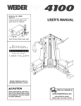
WEIGHT SYSTEM EXERCISER
User's Manual
Serial Number Decal (under seat)
• Assembly
• Adjustments
• Troubleshooting
• Part List and Drawing
Patent Pending
_CAUTION
Read all precautions and instructions in this manual before using
this equipment. Save this manual
for future reference.
Sears, Roebuck and Co., Hoffman Estates, IL 60179
__.,L_._
r[
_
WEIDER
_J_
...............
__
TABLE OF CONTENTS
IMPORTANT PRECAUTIONS
.............................................................
BEFORE YOU BEGIN ...................................................................
ASSEMBLY ...........................................................................
ADJUSTMENTS .......................................................................
WEIGHT RESISTANCE CHART ...........................................................
TROUBLESHOOTING
..................................................................
CABLE DIAGRAMS ....................................................................
ORDERING REPLACEMENT PARTS ................................................
FULL 90 DAY WARRANTY
.......................................................
3
4
5
22
24
25
26
Back Cover
Back Cover
Note: A PART IDENTIFICATION CHART and a PART LIST/EXPLODED DRAWING are attached in the center of
this manual. Remove the PART IDENTIFICATION CHART and the PART LIST/EXPLODED DRAWING before
beginning assembly.
2
IMPORTANT
PRECAUTIONS
,_ i =l,_Anr'.m,lb.mi L nJ,,"_,.
_l_w/._l_r_lll_l_-"
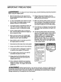
To reduce the risk of serious injury, read the following important precautions
before using the weight system.
1.
2,
Read all instructions in this manual and in
the accompanying literature before using the
weight system,
13. Always disconnect the lat bar from the
weight system when performing an exercise
that does not use the lat bar.
It is the responsibility of the owner to ensure
that all users of the weight system are adequately informed of all precautions.
14. Make sure that the cables remain on the pulleys at all times. If the cables bind while you
are exercising, stop immediately and make
sure that the cables are on all of the pulleys.
The weight system is intended for home use
only. Do not use the weight system in any
commercial, rental, or institutional setting.
.
15. If you feel pain or dizziness at any time while
exercising, stop immediately and begin cooling down.
Use the weight system only on a level surface. Cover the floor beneath the weight system to protect the floor.
4.
16. The warning decals shown here have been
placed on the weight system in the locations
shown on page 4. If a decal is missing or
illegible, please call our Customer Service
Department toll-free at 1-800-999-3756,
Monday through Friday, 6 a.m. until 6 p.m.
Mountain Time, to order a free replacement
decal. Place the decal on the weight system
in the location shown.
Make sure that all parts are properly tightened each time you use the weight system.
Replace any worn parts immediately.
.
Keep children under 12 and pets away from
the weight system at all times.
6,
7.
Keep hands and feet away from moving parts.
8.
Always wear athletic shoes for foot protection.
9.
The weight system is designed to support a
a maximum user weight of 300 pounds.
,,Misuseof this product
may result in serious
_njury.
Read user's manual
md follow all warnings
_ndoperating instructions prior to use.
• Do not allow children
on or around machine.
10. The weight system should not be used by
more than one person at a time.
11. Always stand on the foot plate when performing an exercise that could cause the
weight system to tip.
,, Replacelabel if
damaged, illegible,or
removed.
12. Never release the butterfly arms, leg lever,
squat arm, lat bar, row bar, or handle while
weights are raised. The weights will fall with
great force.
WARNING:
Decal 2
Decal 1
Before beginning this or any exercise pro0ram, consult your physician. This
is especially important for persons over the age of 35 or persons with pre-existing health problems.
Read all instructions before using. Sears assumes no responsibility for personal injury or property
damage sustained by or through the use of this product.
3
BEFORE YOU BEGIN
Thank you for selecting the versatile WELDER_ PRO
4850 weight system. The WELDER® PRO 4850 weight
system offers an impressive array of weight stations
designed to develop every major muscle group of the
body. Whether your goal is to tone your body, build
dramatic muscle size and strength, or improve your
cardiovascular system, the PRO 4850 weight system
will help you to achieve the specific results you want.
reading this manual, call 1-800-4-MY-HOME ®
(1-800--469-4663). To help us assist you, please note
the product model number and serial number before
calling. The model number is 831.153932. The serial
number can be found on a decal attached to the
weight system (see the front cover of this manual for
the location of the decal).
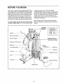
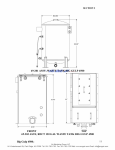
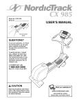
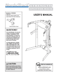
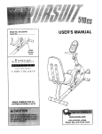
Before reading further, please review the drawing
below and familiarize yourself with the parts that are
labeled.
For your benefit, read this manual carefully before
using the weight system. If you have questionsafter
WARNING
DECAL 1
ASSEMBLED
DIMENSIONS:
Height: 81 in.
Width: 96 in.
Length: 57 in.
Lat Bal
High Pulley Station
Swivel Carriage
WARNING DECAL 2
(one on each side)
Butterfly Arm/Press
Backrest
Squat Arm
Low Pulley Station
Backrest
Curl Pad
Adjustment Knob
Seat
WARNING
DECAL2
Leg Lever
Knee Rest
Weight Stack
4
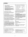
ASSEMBLY
Make sure that you have the following
tools:
Make Assembly Easier
Everything in this manual is designed to
ensure that the weight system can be assembled successfully by anyone.
Before beginning assembly, make sure to
read the information on this page. This
brief introduction will save you much more
time than it takes to read it.
Assembly Requires Two Persons
For your convenience and safety, assemble the
weight system with the help of another person.
• Two adjustable wrenches
__
• One standard screwdriver
cL _:_
• One phillips screwdriver
C_
• One rubber mallet
_:=_!!_E:i'"
..........
-_-_-_
r. .... _
t
• You will also need grease or petroleum jelly, a
small amount of soapy water, and masking tape.
Note: Assembly will be more convenient if you have
a socket set, a set of open-end or closed-end
wrenches, or a set of ratchet wrenches.
How to Identify Parts
Set Aside Enough Time
Due to the many features of the weight system, the
assembly process will require several hours. By
setting aside plenty of time and by deciding to
make the task enjoyable, assembly will go smoothly.
Select a Location for the Weight System
Because of its weight and size, the weight system
should be assembled in the location where it will be
used. Make sure that there is enough room to walk
around the weight system as you assemble it.
To help you identifythe small parts used in assembly,
a PART IDENTIFICATION CHART is included in the
center of this manual. Lay the chart on the floor and
use it to easily identify parts during each assembly
step. Note: Some small parts may have been preattached. If a part is not in the parts bag, check
to see if it has been pre-attached.
How to Orient Parts
As you assemble the weight system, make sure that
all parts are oriented exactly as shown in the drawings.
How to Unpack the Box
Tightening Parts
To make assembly easier, we have divided the
assembly process into four stages. The small hardware needed for each stage is packaged in separate bags. Important: Wait until you begin each
stage to open the parts bag(s) for that stage.
Place all parts of the weight system in a cleared
area and remove the packing materials. Do not dispose of the packing materials until assembly is cornpleted.
Tighten all parts as you assemble them, unless
instructed to do otherwise.
Questions?
If you have questions after reading the assembly
instructions, please call 1-800-4-MY-HOME*
(1-800-469-4663).
The Four Stages of the Assembly Process
Frame Assembly--You will begin by assembling
the base and the uprights that form the skeleton of
the weight system.
Cable Assembly--During this stage, you will
attach the cables and pulleys that connect the
weight stations to the weight stacks.
Arm Assembly--During this stage, you will
assemble the arms and the leg lever.
Seat Assembly--During the final stage, you will
assemble the seat and the backrests.
5
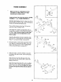
FRAME ASSEMBLY
2
/::5
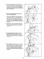
1,
Make sure that you understand all of the
information on page 5 before you begin
assembling the weight system.
96 _;_14
Locate and open the parts bags labeled "FRAME
ASSEMBLY 1" and "FRAME ASSEMBLY 2."
71
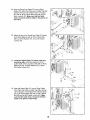
See the inset drawing. Attach the Base Cap (24) to
the Short Base (2) with two M4 x 20ram Self-tapping
Screws (14) and two M4 Washer (98).
106
Press a 50mm Square Inner Cap (105) into the
open end of the Long Base (106).
87
Insert eight M10 x 65mm Carriage Bolts (110) up
through the Long Base (106) and the Short Base (2)
as shown. Note: It may be helpful to place tape
over the heads of the Carriage Bolts to hold
them in place.
,
3,
0
2
Attach the Short Base (2) to the Long Base (106)
with two M10 x 70mm Bolts (85), the Long Frame
Plate (71), and two M10 Nylon Locknuts (87).
110
53
._
Press two 50mm x 75mm Inner Caps (58) into the
Foot Plate (53). Attach the Foot Plate to the Long
Base (106) with two M10 x 65mm Carriage Bolts
(110) and two M10 Nylon Locknuts (87).
58
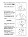
Attach the tether on the Pin w/Tether (112) to the
Long Base (106) with an M4 x 20ram SeLf-tapping
Screw (14).
Attach the four Knee Rest Bumpers (30) to the
Squat Knee Rest (41) with four M4 x 20mm Selftapping Screws (14).
Attach the Squat Knee Rest (41) to the Long Base
(106) with an M10 x 85mm Bolt (96) and an M10
Nylon Locknut (87). Do not overtighten the Nylon
Locknut; the Squat Knee Rest must be able to
pivot.
6
85
58
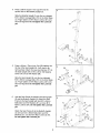
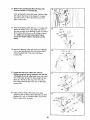
,
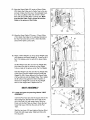
Press a 38mm Square Inner Cap (67) into the
square tube on the Butterfly Upright (3).
Slide the Butterfly Upright (3) onto the two indicated
M10 x 65ram Carriage Bolts (110) in the Short Base
(2). Finger tighten an M10 Nylon Locknut (87) onto
each Carriage Bolt. Do not tighten the Locknuts
yet.
5,
Press a 50mm x 75mm Inner Cap (58) halfway into
the top of the Seat Upright (9); it will need to be
removed later. Attach the Leg Lever Bumper (77) to
the Seat Upright with an M4 x 20ram Self-tapping
Screw (14) and an M4 Washer (98).
58
77
98
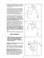
Slide the SeatUpright (9) onto the two indicated
M10 x 65mm Carriage Bolts (110) in the Short Base
(2). Finger tighten an M10 Nylon Locknut {87) onto
each Carriage Bolt. Do not tighten the Locknuts
yet.
8,
87
87..
Hold the Seat Frame (8) between the Seat Upright
(9) and the Butterfly Upright (3). Attach the Seat
Frame to the Seat Upright with two M10 x 95ram
Bolts (92), two M10 Washers (91), and two M10
Nylon Locknuts (87). Do not tighten the Lecknuts
yet,
!
6
8
Attach the Seat Frame (8) to the Butterfly Upright
(3) with two M10 x 95mm Bolts (92), two M10
Washers (91), and two M10 Nylon Locknuts (87).
Do not tighten the Lecknuts yet.
91
7
91
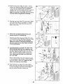
7,
Press a 50mm x 75mm Inner Cap (58) into the top
of the Squat Upright (4). Press two 25ram Round
Outer Caps (120) onto the Upright.
7
Slide the Squat Upright onto the two indicated M 10
x 65mm Carriage Bolts (110) in the Long Base
(106). Finger tighten an M10 Nylon Locknut (87)
onto each Carriage Bolt. Do not tighten the
Locknuts yet.
i,: f
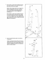
Press a 50mm x 75mm Inner Cap (58) into the top
of the Swivel Upright (5). Slide the Swivel Upright
onto the two indicated M 10 x 65mm Carriage Bolts
(110) in the Long Base (106). Finger tighten an M10
Nylon Locknut (87) onto each Carriage Bolt. De net
tighten the Lecknuts yet.
I
106
8.
Press two Swivel Bushings (66) into the Swivel
Carriage (46).
Tighten an Adjustment Handle (65) into the Swivel
Carriage (46). Orient the Swivel Carriage as shown.
Slide the Carriage onto the Swivel Upright (5) and
engage the Adjustment Handle into an adjustment
hole in the Swivel Upright.
8
66
I/
i f
. 46
65 ----_Y
66 -/1
,/
i _ ft li
87
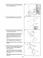
9. Attacha Roller(39)betweentheindicated
setof
holesintheSquatSlider(38)withanM8x 85mm
Bolt(94)andan M8NylonLocknut(86)as shown.
9
39
Do not overtighten the Locknut.
....i,
'i
Assemble the other three Rollers (39) to the
Squat Slider (38) in the same manner.
._-- 86
94 -_,_'"
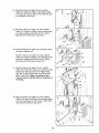
10. Slide the Squat Slider (38) down onto the Squat
Upright (4).
10
ii
11. Orient the Weight Guides (42) with the indicated
holes on top. Insert the ends of two Weight Guides
into the indicated bracket on the Long Base (106).
Slide two Weight Bumpers (49) onto the Weight
Guides. Next, slide ten Weights (44) onto the Weight
Guides. Make sure that the Weights are turned so
the grooved sides of the Weights are facing
downward.
Press a Weight
end of a Weight
into the centers
that the Weight
'
:1
: i
:1p j_
i
:1 j!
Ji
Tube Bumper (48) into the lower
Tube (43). Insert the Weight Tube
of the Weights (44). Make sure
Tube is turned as shown.
Lubricate the two outer holes in a Top Weight (45).
Slide the Top Weight onto the Weight Guides (42).
Make sure that the Top Weight is turned so the
grooved side is facing downward.
44
Apply a number "10" decal to the Top Weight (45) in
the location shown. Apply decats with the numbers
20 through 110 to the ten Weights (44).
Decal
Assemble the other weight stack in the same
way.
ecal
106
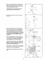
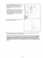
12.AttachtheTopFrame(6)between
theSquatUpright
(4)andtheSwivelUpright(5)withfourM10x95mm
Bolts(92),thetwoShortFramePlates(52),andtwo
M10NylonLocknuts
(87)asshown.Donottighten
the Bolts and Locknuts yet.
12
92
52 i
Attach the four Weight Guides (42) to the Top Frame
(6) with two M10 x 165mm Bolts (95), four M10
Washers (91), and two M10 Nylon Locknuts (87).
52
13. Press two 50mm x 75mm Inner Caps (58) into the
Top Frame (6) and the Butterfly Top Frame (7).
13
Attach the Butterfly Top Frame (7) to the Top Frame
(6) with two M10 x 70mm Bolts (85), two M10
Washers (91), and two M10 Nylon Locknuts (87).
Do not tighten the Locknuts yet.
58
91
Attach the Butterfly Top Frame (7) to the Butterfly
Upright (3) with two M10 x 95mm Bolts (92), two
M10 Washers (91), and two M10 Nylon Locknuts
(87).
58
Tighten all of the M10 Nylon Locknuts (87) used
in steps 2-13.
i
14
ARM ASSEMBLY
87
21
14. Open the parts bag labeled "ARM ASSEMBLY."
Press three 40mm x 50mm Inner Caps (21) into the
Leg Lever (10). Attach the Eyebolt (116) to the Leg
Lever with an M10 Washer (91) and an M10 Nylon
Locknut (87).
Lubricate an M10 x 65mm Bolt (59) with grease.
Turn the Leg Lever (10) so that the welded tab is
on the indicated side, and attach the Leg Lever to
the Seat Upright (9) with the Bolt and an M10 Nylon
Locknut (87). Do not overtighten the Locknut;
the Leg Lever must be able to pivot easily.
21
15
i
34
15. Press a 50mm x 70mm Inner Cap (34) into the
Butterfly Frame (47). Attach the tethers on the two
"L"-pins w/Tether (60) to the ButterfÊy Frame with an
M4 x 20mm Self-tapping Screw (14).
87
"_
107--Lubricate
,,'
!
Lubricate a an M10 x 75mm Bolt (107) with grease.
Attach the Butterfly Frame (47) to the Butterfly Top
Frame (7) with the Bolt and an M10 Nylon Locknut
(87). Do not overtighten the Locknut; the
Butterfly Frame must be able to pivot easily.
10
47
14;
=
16. Press a 40mm x 50mm Inner Cap (21) into the Right
Butterfly Arm (26). Wet the lower end of the Arm and
a Long Pad (54) with soapy water• Slide the Long
Pad onto the Arm.
16
Lubricate
2%
/
Ailach the Press Handle (27) to the Right Butterfly
Arm (26) with two M8 x 20mm Button Head Screws
(51). Slide the Long Pad (54) down so that the bottom is flush with the lower end of the Arm. Wet the
Press Handle with soapy water. Slide a Long
Handgrip (28) onto the Press Handle. Press a 25ram
Round Inner Cap (29) into the Press Handle.
i//
Lubricate an M10 x 50mm Bolt (100) with grease.
Attach a Pivot Bracket (70) to the Right Butterfly
Arm (26) with the Bolt and an M10 Nylon Locknut
(87). Do not overtighten the Locknut; the Pivot
Bracket must be able to pivot easgy. Repeat this
step with the Left Butterfly Arm (25).
17. Lubricate an M10 x 80mm Button Head Bolt (104)
and both sides of two Plastic Washers (56) with
grease. Attach the Right Butterfly Arm (26) to the
Butterfly Frame (47) with the Bolt, the two Plastic
Washers, two Butterfly Caps (57), two M10
Washers (91), and an M10 Nylon Locknut (87) as
shown. Make sure that the recessed sides of the
Plastic Washers are fitted over the welded bushing in the Butterfly Arm. Do not overtighten the
Locknut; the Butterfly Arm must be able to pivot
easily.
17
26
56
Repeat this step with the Left Butterfly Arm (25).
CABLE ASSEMBLY
_- 2/
18.
IMPORTANT: Refer to the Cable Identification
Chart on page 26 for help identifying the
cables. Do not overtighten the bolts and
nuts attaching the pulleys. The pulleys must
be ab!e to turn freely.
18
78
74
95
Locate and open the parts bags labeled "CABLE
ASSEMBLY" and "PULLEYS."
Lubricate the M10 x 165mm Bolt (95) with grease.
Attach the Swivel Cage (76) to the Swivel Carriage
(46) with the Bolt and an M10 Nylon Locknut (87).
Locate the Swivel High Cable (74), which is
3200mm long and has a ball on one end and a
threaded bolt on the other end. Remove the
upper 90mm Pulley (78) from the Swivel Cage (76).
Wrap the Cable around the Pulley. Reattach the
Pulley to the Swivel Cage with the M10 x 45mm
Bolt (93) and the M10 Nylon Locknut (87).
11
76/,
87
Ji
19. Route the Swivel High Cable (74) through the Swivel
Upright (5) and over a 115mm Pulley (119). Attach
the Pulley inside the Upright with an M10 x 65mm
Bolt (59), two M10 Washers (91), two 12.5 Spacers
(69), and an M10 Nylon Locknut (87).
19
5
Attach an M10 x 65mm Bolt (59), two M10 Washers
(91), and an M10 Nylon Locknut (87) to the Swivel
Upright (5).
91
59
9
20. Remove the preattached 90mm Pulleys (78)
from the Small Pulley Plates (31).
74
2O
Wrap the Swivel High Cable (74) over a 90mm
Pulley (78). Attach the Pulley and a Cable Trap (68)
to the second set of holes from the top of the Small
Pulley Plates (31) with an M10 x 50mm Bolt (100)
and an M10 Nylon Locknut (87). Make sure the
Cable Trap is turned to hold the Cable in the
groove of the Pulley.
21. Wrap the Swivel High Cable (74) over a 115mm
Pulley (119). Attach the Pulley inside of the indicated bracket on the Top Frame (6) with an M10 x
45mm Bolt (93) and an M10 Nylon Locknut (87).
100
31
31
21
6
119
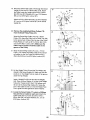
22. Lift the Weight Tube (43) and the Top Weight (45)
closest to the Swivel Upright (5). Make sure that the
small pin on the Weight Tube is inside of the groove
under the Top Weight.
22
insert a Weight Pin (50) into the stack of Weights
(44). Place a 50mm Washer (1) on top of the Weight
Tube (43). Thread an M12 Nut (118) halfway onto
the end of the Swivel High Cable (74). Screw the
end of the Cable two full turns into the Weight Tube.
Then, tighten the Nut against the 50mm Washer.
23
23. Locate the Swivel Cable (17), which is 2930mm
long and has an eyelet on each end. Attach the
Cable inside the Top Frame (6) with an M10 x
65ram Bolt (59), two M10 Washers (91), and an
M10 Nylon Locknut (87).
12
74
24. Remove the preattached 90ram Pulleys (78)
from the Offset Double "U"-bracket (61).
24
!j'"
Wrap the Swivel Cable (17) around a 90mm Pulley
(78). Attach the Pulley to the Offset Double "U"bracket (61) with an MIO x 45ram Bolt (93) and an
M10 Nylon Locknut (87).
!
/_
93
i
J=
!
61
,
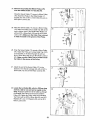
25. Wrap the Swivel Cable (17) around a 90mm Pulley
(78). Attach the Pulley and a Cable Trap (68) to the
next to bottom hole in the Small Pulley Plates (31)
with an M10 x 50mm Bolt (100) and an M10 Nylon
Locknut (87). Make sure the Cable Trap is turned
to hold the Cable in the groove of the Pulley•
r
25
r'; i!lil
31_
#"
174
26. Wrap the Swivel Cable (17) around a 90mm Pulley
(78). Attach the Pulley and a long Cable Trap (102)
to the bracket on the Swivel Upright (5) with an
M10 x 50mm Bolt (100) and an M10 Nylon Locknut
(87). Make sure the Cable Trap is turned to hold
the Cable in the groove of the Pulley•
26
27. Attach the end of the Swivel Cable (17) to the
bracket on the Swivel Carriage (46) with an M10 x
20mm Bolt (13) and an M10 Nylon Locknut (87).
27
102
46/r - _
87_._
'i
io
J i
f
}
f_
28. Locate the Lat Cable (88), which is 2310mm long
and has a ball on one end and an eyelet on the
other. Route the eyelet end of the Cable up through
the Butterfly Top Frame (7) and around a 90ram
Pulley (78). Attach the Pulley inside of the ButteRy
Top Frame with an M10 x 65mm Bolt (59), two M10
Washers (91), two 12.5 Spacers (89), and an M10
Nylon Locknut (87).
28
87
13
100
29. Wrap the Lat Cable (88) around a 90mm Pulley
(78). Attach the Pulley and a Long Cable Trap (102)
to the Top Frame (6) with an M10 x 50mm Bolt
(100) and an M10 Nylon Locknut (87). Make sure
the Cable Trap is turned to hold the Cable in the
groove of the Pulley.
29
78
30. Remove the preattached 90mm Pulleys (78)
from the Pulley Plates (63).
=
100
Wrap the Lat Cable (88) around a 90mm Pulley
(78). Attach the Pulley and a Cable Trap (68) to the
second set of holes from the top of the Pulley
Plates (63) with an M10 x 50mm Bolt (100) and an
M10 Nylon Locknut (87). Make sure the Cable
Trap is turned to hold the Cable in the groove of
the Pulley.
63
31. Attach the end of the Lat Cable (88) inside of the
Butterfly Top Frame (7) with an M10 x 65mm Bolt
(59), two M10 Washers (91), and an M10 Nylon
Locknut (87).
31
32. Locate the Butterfly Cable (69), which is the
shortest Cable. Attach the Cable to the Pivot
32
Bracket (70) on the Left ButterflyArm (25) with an
M8 x 25mm Shoulder Bolt (103) and an M8 Nylon
Locknut (87).
33. Wrap the Butterfly Cable (69) over a "V"-pulley (55).
Attach the Pulley and a Long Cable Trap (102) to
the indicated bracket on the Butterfly Upright (3)
with an M10 x 60mm Bolt (18) and an M10 Nylon
Locknut (87). Make sure that the Long Cable
Trap is turned to hold the Cable in the groove of
the Pulley.
33
102
181
69
14
34. Remove the preattached 90mm Pulleys (78)
from the Double "U"-bracket (62).
Wrap the Butterfly Cable (69) under a 90mm Pulley
(78). Attach the Pulley to the Double "U"-bracket
(62) with an M10 x 45mm Bolt (93) and an M10
Nylon Locknut (87).
, 93
"_i'm 87
• 62_,_¢"
35. Wrap the Butterfly Cable (69) over a "V"-pulley (55).
Attach the Pulley and a Long Cable Trap (102) to
the ether bracket on the Butterfly Upright (3) with an
M19 x 60mm Bolt (18) and an M10 Nylon Locknut
(87). Make sure that the Long Cable Trap is
turned to hold the Cable in the groove of the
Pulley•
35
i
18--_
_
I
3
I i r
-@-<¢
36. Attach the Butterfly Cable (69) to the Pivot Bracket
(70) on the Right Butterfly Arm (26) with an M8 x
25mm Shoulder Bolt (103) and an M8 Nylon
Locknut (86).
36
37. Locate the Leg Lever Cable (75), which is
2250mm long and has an eyelet on one end and
a threaded pin on the other end. Route the eyelet
end of the Cable through the Seat Upright (9) and
attach it to the tab on the Leg Lever (10) with an
M8 x 25ram Shoulder Bolt (103) and an M8 Nylon
Locknut (86).
37
86
\.
103
38. Attach a 90ram Pulley (78) inside of the Seat
Upright (9) with an M10 x 65ram Bolt (59), two M10
Washers (91), two 12.5 Spacers (89), and an M10
Nylon Locknut (87), as shown.
38
91
.59
89
15
39. Route the Leg Lever Cable (75) under a 115mm
Pulley (119). Attach the Pulley and a Large Cable
Trap (113) to the indicated side of the Butterfly
Upright (3) with an M10 x 95ram Bolt (92), two M10
Washers (91), and an M10 Nylon Locknut (87).
Make sure that the Large Cable Trap is turned to
hold the Cable in the groove of the Pulley.
40. Wrap the Leg Lever Cable (75) over a 90mm Pulley
(78). Attach the Pulley to the Double "U"-bracket
(62) with an M10 x 45mm Bolt (93) and an M10
Nylon Locknut (87).
40
i *
62
' ',
L
.- --'Jb_,__.'_,_, ,
41. Remove the preattached 90mm Pulley (not
shown) from the "U"-bracket (64).
Attach the end of the Leg Lever Cable (75) to the
"U"-bracket (64) with an M8 Washer (90) and an M8
Nylon Locknut (86). Note: Do not completely
tighten the Locknut; It should be threaded only
two turns onto the end of the Cable, as shown
in the inset drawing.
42. Locate the Swivel Low Cable (72), which is the
only remaining cable that has an eyelet on one
end and a ball on the other end, Route the eyelet
end of the Cable through the cage on the Long
Base (106) and through the Swivel Upright (5) as
shown. Make sure the Cable is over the short
bar in the cage.
42
Attach a 90mm Pulley (78) to the indicated bracket
on the Long Base (106) with M10 x 45ram Bolt (93)
and an M10 Nylon Locknut (87). Make sure the
Cable is in the groove of the Pulley.
43. Wrap the Swivel Low Cable (72) under a 90mm
Pulley (78). Attach the Pulley to the indicated bracket on the Long Base (106) with an M10 x 45mm
Bolt (93) and an M10 Nylon Locknut (87).
16
i
44. Wrap the Swivel Low Cable (72) over a 90mm
Pulley (78). Attach the Pulley to the Offset Double
"U"-bracket (61) with an M10 x 45mm Bolt (93) and
an M1O Nylon Locknut (87).
45. Wrap the Swivel Low Cable (72) under a 90mm
Pulley (78). Attach the Pulley to the indicated bracket on the Long Base (106) with an M10 x 45mm
Bolt (93) and an M10 Nylon Locknut (87).
46. Route the Swivel Low Cable (72) under the indicated stack of Weights (44).
Wrap the Swivel Low Cable (72) under a 90mm
Pulley (78). Attach the Pulley to the indicated bracket on the Long Base (106) with an M10 x 45mm
Bolt (93) and an M10 Nylon Locknut (87).
47. Wrap the Swivel Low Cable (72) over a 90mm
Pulley (78). Attach the Pulley and a Cable Trap (68)
between the indicated holes in the Pulley Plates
(63) with an M10 x 50mm Bolt (100) and an M10
Nylon Locknut (87). Make sure that the Cable
Trap is turned to hold the Cable in the groove of
the Pulley,
48, Wrap the Swivel Low Cable (72) under a 90mm
Pulley (78). Attach the Pulley to the indicated bracket on the Short Base (2) with an M10 x 45mm Bolt
(93) and an M10 Nylon Locknut (87).
17
49. Wrap the Swivel Low Cable (72) over a 90mm
Pulley (78). Attach the Pulley and a Cable Trap (68)
between the lower set of holes in the "U"-bracket
(64) with an M10 x 50mm Bolt (100) and an M10
Nylon Locknut (87). Make sure that the Cable
Trap is turned to hold the Cable in the groove of
the Pulley.
49
72
50. Attach the end of the Swivel Low Cable (72) inside
of the Short Base (2) with an M10 x 65mm Bolt
(59), two M10 Washers (91), and an M10 Nylon
Locknut (87).
5O
72
51. Locate the Squat Cable (73), which is the only
remaining cable. Attach the eyelet end of tbe
Cable inside of the Long Base (106) with an M10 x
65ram Bolt (59), two M10 Washers (91), and an
M10 Nylon Locknut (87).
52. Wrap the Squat Cable (73) over a 90mm Pulley
(78). Attach the Pulley, a Cable Trap (68), and two
19mm Spacers (101) between the indicated brackets on the Squat Slider (38) with an M10 x 85mm
Bolt (96) and an M10 Nylon Locknut (87). Make
sure that the Cable Trap is turned to hold the
Cable in the groove of the Pulley.
18
59
53. Wrap the Squat Cable (73) under a 90mm Pulley
(78). Attach the Pulley and a Cable Trap to the second set of holes from the top in the indicated bracket on the Long Base (106) with an M10 x 50mm
Bolt (100) and an M10 Nylon Locknut (87). Make
sure that the Cable Trap is turned to hold the
Cable in the groove of the Pulley.
54. Wrap the Squat Cable (73) over a 115mm Pulley
(119). Attach the Pulley to the indicated bracket on
the Top Frame (6) with an M10 x 45mm Bolt (93)
and an M10 Nylon Locknut (87).
54
6
87
119
55. Place a 50mm Washer (1) on top of the Weight Tube
(43) closest to the Squat Upright (4). Thread an M 12
Nut (118) halfway onto the end of the Squat Cable
(73).
Lift the Weight Tube (43) and the Top Weight (45)
and make sure that the small pin on the Weight
Tube is inside of the groove under the Top Weight.
Hold the Weight Tube (43) and the Top Weight (45)
a few inches over the weight stack and insert the
Weight Pin (50). Screw the end of the Squat Cable
(73) two full turns into the Weight Tube. Then, tighten
the M12 Nut (118) against the 50ram Washer (1).
Remove the Weight Pin and set the Top Weight
back on the weight stack, Replace the Pin.
SEAT ASSEMBLY
56
56. Locate and open the parts bag labeled "SEAT
ASSEMBLY."
Insert the Pad Tube (23) into the square hole in the
Seat Upright (9). Wet the Tube and inside of the
two Knee Pads (19) with soapy water. Slide the
Pads onto the Pad Tube as shown, Press the two
Knee Pad Caps (109) into the ends of the Pad
Tube.
2O
10
Wet the Leg Lever (10) and inside of the two Short
Pads (20) with soapy water. Slide two Pads onto
the Leg Lever.
109
2O
19
57.AttachtheSeat(16)totheSeatFrame(8)withtwo
M6x 16mmScrews(114),an M6x 65mmScrew
(99),andanM6Washer(97).
58. Attachthe ButterflyBackrest
(15)tothe Butterfly
Upright(3)withfourM6x 16mmScrews(114).
57
58
=
15_,114
59.WetoneendoftheSquatArm(32)andinsideofa
ShortPad(20)withsoapywater.SlidethePad(20)
ontotheSquatArmas shown.
59
AttachtheSquatHandle(33)totheSquatArm(32)
withtwoM8x 20mmButtonHeadScrews(51).
Slidea 50mmOuterCapw/Hole(111)ontothe
SquatHandleandpressitontotheendofthe
SquatArm.SlidetheShortPad(20)overthe
Screws.
WettheSquatHandlewithsoapywater.Slidean
200mmHandgrip
(84)ontotheSquatHandle.
,_;- "_
111
84
Repeat this step with the other end of the Squat
Arm (32).
6O
60. Attach the Squat Arm (32) to the Squat Bracket (37)
with two M10 x 65mm Carriage Bolts (110) and two
M10 Nylon Locknuts (87). Do not tighten the
Nylon Locknuts yet.
Finish attaching the Squat Arm (32) to the Squat
Bracket (37) with two M10 x 70mm Carriage Bolts
(108), two M10 Washers (91), and two M10 Nylon
Locknuts (87).
32
110
Tighten all of the M10 Nylon Locknuts (87) used
in this step.
20
61. Turn the Squat Backrest (35) so that the four screw
holes are closer to the bottom of the Squat
Backrest than the top. Attach the Squat Backrest to
the Squat Bracket (37) with four M6 x 16mm
Screws (114).
61
37
114
Turn the Adjustment Knob (115) counterclockwise
several times to loosen it. Next, pull the Knob and
slide the Squat Bracket (37) down onto the Squat
Slider (38). Engage the Knob into one of the holes
in the Squat Slider, and then turn the Knob clockwise until it is tight.
62
62. Attach the Curl Pad (11) to the Curl Post (12) with
two M4 x 16mm Screws (114).
114
63. Make sure that all parts have been properly tightened. The use of the remaining parts will be explained in
ADJUSTMENTS, beginning on page 22 of this manual.
Before using the weight system, pull each cable a few times to make sure that the cables move smoothly
over the pulleys. If one of the cables does not move smoothly, find and correct the problem. IMPORTANT: If
the cables are not properly installed, they may be damaged when heavy weight is used. See the
CABLE DIAGRAMS on page 26 and 27 of this manual for proper cable routing. If there is any slack in
the cables, you will need to remove the slack by tightening the cables. See TROUBLESHOOTING on
page 25.
21
ADJUSTMENTS
The instructions below describe how each part of the weight system can be adjusted. Refer to the exercise
guide accompanying this manual to see how the weight system should be set up for various exercises. IMPORTANT: When attaching the lat bar, row bar, or handle, make sure that the attachments are in the correct
starting position for the exercise to be performed. If there is any slack in the cables or chain as an exercise is performed, the effectiveness of the exercise will be reduced.
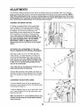
CHANGING THE WEIGHT SETTING
To change the weight setting of either weight stack,
inserL a Weight Pin (50) under the desired Weight
(44) until the bent end of the Weight Pin is touching
the Weights. Turn the bent end downward. The
weight setting of each weight stack can be changed
from 10 pounds to 110 pounds, in 10-pound increments. Note: Due to the cables and pulleys, the
amount of resistance at each exercise station may
vary from the weight setting. Use the WEIGHT
RESISTANCE CHART on page 24 to find the
approximate amount of resistance at each weight
station.
ATTACHING THE ACCESSORIES TO THE HIGH
PULLEY STATION OR THE LOW PULLEY STATION
Attach the Lat Bar (79) to the Lat Cable (88) with a
Cable Clip (83). For some exercises, the Chain (81)
should be attached between the Lat Bar and the Lat
88_
Cable with two Cable Clips. Adjust the length of the
Chain between the Lat Bar and the Lat Cable so the
Lat Bar is in the correct starting position for the
exercise to be performed.
81
83
The Lat Bar (79) can be attached to the Swivel Low
Cable (not shown) in the same way.
-
__-__Y_'_'
kJ
79
The Row Bar (not shown), the Handle (not shown), or
Ab Strap (not shown) can be attached to the Lat Cable
(88) or the Swivel Low Cable (not shown) in the same
way.
CONVERTING THE BUTTERFLY ARMS
To use the Butterfly Arms (25, 26) as butterfly arms,
insert the "L"-pins w/Tethers (60) into the butterfly holes
in the Butterfly Upright (3).
To use the Butterfly Arms (25, 26) as press arms, insert
the "L"-pins w/Tethers (60) into the press holes in the
Butterfly Frame (47).
Make sure that both "L"-pins w/Tethers (60) are fully
inserted into the same set of holes before performing any exercise.
22
Holes
25
,',
x
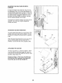
ADJUSTING THE SQUAT ARM OR SWIVEL
CARRIAGE
32
To adjust the height of the Squat Arm (32), first turn
the Adjustment Knob (115) on the Squat Bracket (37)
counterclockwise several turns to loosen it. Next, pull
the Handle and slide the Squat Bracket up or down to
the desired position. Engage the Handle into one of
the holes in the Squat Slider (not shown), and then
turn the Handle clockwise until it is tight.
The height of the Swivel Carriage (not shown) can be
adjusted in the same way using the Adjustment
Handle (not shown).
ADJUSTING THE SQUAT KNEE REST
To use the Squat Knee Rest (41), pivot it down to the
position shown and insert the Pin w/Tether (112) into
the holes in the Squat Knee Rest and the Long Base
(106).
112
106
When the Squat Knee Rest (41) is not in use, pivot it
up to a vertical position and then insert the Pin
w/Tether (112) into the hole in the Long Base (106).
ATTACHING THE CURL PAD
To use the Curl Pad (11), remove the 50mm x 75mm
Inner Cap (58) from the Seat Upright (9). Insert the
Curl Post (12) into the Seat Upright and secure it with
the M10 x 20mm Knob (117).
Replace the 50mm x 75mm Inner Cap (58) when
the Curl Post (12) is removed. Do not press the
Cap all the way into the Seat Upright (9),
/
23
./
d'-"
/
41
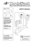
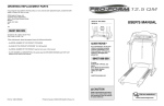
WEIGHT RESISTANCE CHART
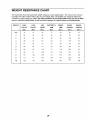
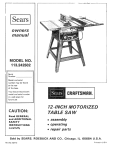
The chart below shows the approximate weight resistance at each weight station, "Top" refers to the 10-pound
top weight. The other numbers refer to the 10-pound weight plates. The butterfly arm resistance listed is the
resistance for each butterfly arm. Note: The actual resistance at each weight station may vary due to differences in individual weight plates as well as friction between the cables, pulleys, and weight guides.
WEfGHT
HIGH
LOW
LEG
BUTTERFLY
PRESS
SQUAT
SWIVEL
PULLEY
PULLEY
LEVER
ARM
ARM
STATION
STATION
(Ibs.)
(Ibs,)
(Ibs,)
(Ibs,)
(Ibs,)
(Ibs.)
(Ibs.)
Top
14
14
22
17
24
59
16
1
25
25
35
26
39
87
26
2
38
36
53
36
55
116
39
3
48
44
67
45
70
136
52
4
61
60
91
54
89
170
59
5
68
70
11!
63
104
192
74
6
80
80
122
71
118
203
84
7
96
91
148
80
136
223
90
8
101
104
160
91
154
239
104
9
112
111
184
100
167
254
116
10
122
122
190
108
187
270
122
24
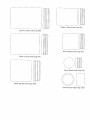
TROUBLESHOOTING
Make sure all parts are properly tightened each time the weight system is used. Replace any worn parts immediately. The weight system can be cleaned using a damp cloth end mild non-abrasive detergent. Do not use solvents.
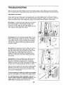
TIGHTENING THE CABLES
Woven cable, the type of cable used on the weight system, can stretch slightly when it is first used. If there is
slack in the cables before resistance is felt, the cables should be tightened. To tighten the cables first insert the
weight pins into the centers of the weight stacks. Slack can be removed from the cables in several ways:
See drawing 1. To tighten the Squat Cable (73) or the Swivel
High Cable (not shown), first loosen the M12 Nut (118) on
the end of the Cable, away from the 50mm Washer (1).
Screw the end of the Cable farther into the Weight Tube (43).
Then, retighten the Nut against the Washer.
See drawing 2. To further tighten the Squat Cable (73), first
remove the M10 Nylon Locknut (87), the M10 x 50mm Bolt
(100), Cable Trap (68), and 90mm Pulley (78) from the indicated bracket on the Long Base (106). Reattach the Pulley
and Cable Trap between a lower set of holes with the Bolt
and Nylon Locknut.
_
106
100
See drawing 3. To tighten the other five cables, first remove
the upper or lower M10 Nylon Locknut (87), M10 x 50mm
Bolt (100), 90mm Pulley (78), and Cable Trap (68) from the
Pulley Plates (63) or Small Pulley Plates (not shown).
Reattach the Pulley and the Cable Trap between a set of
holes closer to the center of the Pulley Plates with the Bolt
and Locknut.
See drawing 4. To remove additional slack, first remove the
M10 Nylon Locknut (87), M10 x 50mm Bolt (100), 90mm
Pulley (78), and Cable Trap (68) from the "U"-bracket (64).
Reattach the Pulley and the Cable Trap between the higher set
of holes in the "U"-bracket with the Bolt and Nylon Locknut.
Slack can also be removed from the cables by tightening the
M8 Nylon Locknut (86) at the end of the Leg Lever Cable
(75). To do this you may need to remove the 90ram Pulley
(78) from the "U"-Bracket (64).
Do not overtighten the cables. If the cables are overtightened, the top weights will be lifted off the weight stacks.
If a cable slips off the pulleys repeatedly, it may have
become twisted. Remove the cable and re-install it. if the
cables need to be replaced, see ORDERING REPLACEMENT PARTS on the back cover of this manual.
25
t
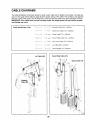
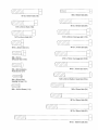
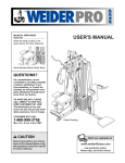
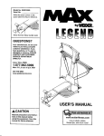
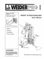
CABLE DIAGRAMS
The cable identification chart below shows the ends of each cable and the lengths of the cables. The cable diagrams on this page and the following page show the proper routing of the cables. The numbers in the diagrams
show the routes of the cables. Use the diagrams to make sure that the cables have been assembled correctly.
IMPORTANT: If the cables have not been correctly routed, the weight system will not function properly
and damage may occur.
Cable Identification Chart
Butterfly Cable (69)--1400mm
Swivel Low Cable (72)--5500mm
Squat Cable (73)--4425mm
Swivel High Cable (74)--3200mm
Leg Lever Cable (75)--o2250mm
Lat Cable (88)-----2310mm
Swivel Cable (17)--2930mm
Swivel High Cable (74)
Lat Cable (88)
4
4
2
Squat Cable (73)
2_.
1\
5
i!
Butterfly
Cable (69)
i
i
J
i'
7
i
L
26
i
Leg Lever
Cable (75)
i_
_t=
f
:r
Swivel Low _=_ =,
Cable (72)
' _'
i
i
Swivel Cable (17)
27
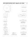
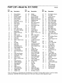
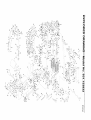
PART IDENTIFICATION
CHART--Model
No. 831.153932
H-
--
f
,? .?
12,5mm
Z--
,
i
19mm
50mm Washer
M10 Washer
R040
•
Spacer
(89)
--.\
,
r
Spacer
(101)
(1)
(91)
J
j
i
/
M8 Washer (90)
115mm Pulley (119)
(Not shown to scale)
M6 Washer
(97)
M4 Washer
(98)
"V"-pulley (55)
(Not shown to scale)
M12 Nut (118)
A"
'
_.........i
i
M10 Nylon Locknut
i
(87)
M8 Nylon Locknut (86)
90ram Pulley (78)
(Not shown to scale)
M6 x 65ram Bolt (99)
M10x 60mmBolt(18)
r
':_c-t
,
,,':,--I"
......
i
" _-"_...........................................
_W\
\,/
__':,._k'_,,
L.._..."._....,I
..............................
L.......J
----q
1
i
............
i
MI0 x 65ram
Bolt (59)
M10 x 50mm Bolt (100)
i-'\
i
b,tI
M10 x45mm
M10 x 65mm Carriage Bolt (110)
Bolt (93)
_x_
i4
D,.2',._
L.'::_}'_..!-I
............................................
--!
M10 x20mm
M10x
Bolt (13)
Mw"i:
.... ,_;W,,,
'-
_
M8 x 25ram
Shoulder Bolt (103)
¢_T
70mm Bolt (85)
7,17q-
_- _",.
,,\ _&!d
......__
.......
.[-i
;
-,,,
- \
',,
MIO x 70mm Carriage
Bolt (108)
MIO x 75mm Bolt (107)
M8 x 20mm Button
Head Screw (51)
M4 x 20ram Selftapping Screw (14)
MIO x 80mm Button Head Bolt (104)
M8 x 85mm Bolt (94)
M6 x 16ram Screw (114)
M10 x 85ram
F.........
I
t
J
Bolt (96)
................................................................................................
M!0 x 95ram Bolt (92)
c i:tl
..........................
M10 x 165mm Bolt (95)
f
iLi!J
r[
40mm x 50ram Inner Cap (21)
50mm x 75mm Inner Cap (58)
Ii
i
:E,
i
i
:ii
iii
38mm Square Inner Cap (67)
50mm x 70mm Inner Cap (34)
f
...........................................................
25ram Round Inner Cap (29)
t't
i
J,
I
50mm Square Inner Cap (105)
J
25mm Round Outer Cap (120)
PART LISTmModel No. 831.153932
Key
No.
Qty.
1
2
3
4
5
6
7
8
2
1
1
1
1
1
1
1
50ram Washer
Short Base
Butterfly Upright
Squat Upright
Swivel Upright
Top Frame
Butterfly Top Frame
Seat Frame
9
10
11
12
13
14
1
1
1
1
1
9
15
16
17
18
19
20
21
1
1
1
2
2
4
5
22
23
24
25
26
27
28
29
1
1
1
1
1
2
2
2
30
31
32
33
34
4
2
1
2
1
35
36
37
38
39
40
41
42
43
1
4
1
1
4
8
1
4
2
Seat Upright
Leg Lever
Curl Pad
Curl Post
M10 x 20mm Bolt
M4 x 20mm Self-tapping Screw
Butterfly Backrest
Seat
Swivel Cable
M10 x 60mm Bolt
Knee Pad
Short Pad
40mm x 50mm Inner
Cap
Ab Strap
Pad Tube
Base Cap
Left Butterfly Arm
Right Butterfly Arm
Press Handle
Long Handgrip
25ram Round Inner
Cap
Knee Rest Bumper
Small Pulley Plate
Squat Arm
Squat Handle
50mm x 70ram Inner
Cap
Squat Backrest
135mm Handgrip
Squat Bracket
Squat Slider
Roller
Roller Bearing
Squat Knee Rest
Weight Guide
Weight Tube
Description
Key
No.
Qty.
44
45
46
47
48
49
50
51
20
2
1
1
2
4
2
8
52
53
54
55
56
57
58
2
1
2
2
4
4
7
59
60
61
9
2
1
62
63
64
65
66
67
1
2
1
1
2
1
68
69
70
71
72
73
74
75
76
77
78
79
80
81
82
83
84
85
86
7
1
2
1
1
1
1
1
1
1
22
1
1
1
1
3
2
4
8
R0403A
Key
No.
Qty.
Weight
Top Weight
Swivel Carriage
Butterfly Frame
Weight Tube Bumper
Weight Bumper
Weight Pin
M8 x 20mm Button
87
88
89
90
91
92
93
94
71
1
6
1
37
11
13
4
M10 Nylon Locknut
Lat Cable
12.5mm Spacer
M8 Washer
M10 Washer
M10 x 95mm Bolt
M10 x 45mm Bolt
M8 x 85mm Bolt
Head Screw
Short Frame Plate
Foot Plate
Long Pad
"V"-pulley
Plastic Washer
Butterfly Cap
50mm x 75mm Inner
Cap
M10 x 65mm Bolt
"L"-pin w/Tether
Offset Double
"U"-bracket
Double "U"-bracket
Pulley Plate
"U"-bracket
Adjustment Handle
Swivel Bushings
38mm Square Inner
Cap
Cable Trap
Butterfly Cable
Pivot Bracket
Long Frame Plate
Swivel Low Cable
Squat Cable
Swivel High Cable
Leg Lever Cable
Swivel Cage
Leg Lever Bumper
90mm Pulley
Lat Bar
Row Bar
Chain
Handle
Cable Clip
200mm Handgrip
M10 x 70mm Bolt
M8 Nylon Locknut
95
96
97
98
99
100
101
102
103
3
2
1
3
1
10
2
4
3
104
2
105
1
106
107
108
1
1
2
109
110
2
12
111
2
112
113
114
115
116
117
118
119
120
1
1
12
1
1
1
2
4
2
#
#
#
#
1
1
2
1
M10 x 165mm Bolt
M10 x 85mm Bolt
M6 Washer
M4 Washer
M6 x 65ram Bolt
M10 x 50mm Bolt
19mm Spacer
Long Cable Trap
M8 x 25mm Shoulder
Bolt
M10 x 80mm Button
Head Bolt
50mm Square Inner
Cap
Long Base
M10 x 75mm Bolt
M10 x 70mm
Carriage Bolt
Knee Pad Cap
M10 x 65mm
Carriage Bolt
50mm Outer Cap
w/Hole
Pin w/Tether
Large Cable Trap
M6 x 16mm Screw
Adjustment Knob
Eyebolt
M10 x 20mm Knob
M12 Nut
115mm Pulley
25mm Round Outer
Cap
User's Manual
Exercise Guide
Grease Packet
Allen Wrench
Description
Description
Note: "#" indicates a non-illustrated part. Specifications are subject to change without notice. If a part is missing,
call toll-free 1-800-999-3756. See the back cover of the user's manual to order replacement parts.
21
_U
0
0
O3
>
Your Home
For repair - in your home - of all major brand appliances, lawn and garden equipment,
or heating and cooling systems, no matter who made it, no matter who sold itf
iiii_ii
For the replacement parts, accessories, and user's manuals that you need to do-it-yourself.
_i_i
_
For Sears professional installation of home appliances
and items like garage door openers and water heaters.
1-800-4-MY-HOME
®
Anytime, day or night
(U.S.A. and Canada)
www, seara.ca
(1-800-469-4663)
www.eears.com
Our Home
For repair of carry-in products like vacuums, lawn equipment,
and electronics, call or go on-line for the location of your nearest
Sears Parts and Repair Center,
1-800-488-1222
Anytime, day or night (U.S.A. only)
www.sears.com
To purchase a protection agreement (U.S.A.)
or maintenance agreement (Canada) on a product serviced by Sears:
1-800-827-6655
(u.s A)
1-800-361-6665
(Canada)
Para pedir servicio de reparaci6n a domicilio, y para ordenar piezas:
1-888-SU-HOGAR sM (1-888-784-6427)
@ Registered Trademark / _ Trademark / SMService Mark of Sears, Roebuck and Co,
® M_trca Registrada / _MMarca de F&bdca / SMMarca de Servicio de Sears, Roebuck and Co,
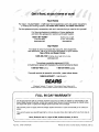
FULL 90 DAY WARRANTY
For 90 days from the date of purchase, if failure occurs due to defect in material or workmanship in this
Sears Weight System Exerciser, contact the nearest Sears Service Center throughout the United States
and Sears witl repair or replace the Weight System Exerciser, free of charge.
This warranty does not apply when the Weight System Exerciser is used commercially or for rental purposes.
This warranty gives you specific legal rights, and you may also have other rights which vary from state to
state.
Sears, Roebuck and Co., Dept. 817WA, Hoffman Estates, IL 60179
J
Part No. 194013 R0403A
Printed in China Q 2003 Sears, Roebuck and Co.