1
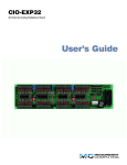
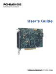
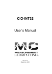
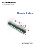
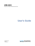
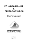
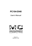
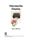
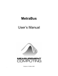
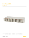
PC104-DAS08 User’s Manual Revision 4 September, 2001 Your new Measurement Computing product comes with a fantastic extra — Management committed to your satisfaction! Thank you for choosing a Measurement Computing product—and congratulations! You own the finest, and you can now enjoy the protection of the most comprehensive warranties and unmatched phone tech support. It’s the embodiment of our mission: To provide data acquisition hardware and software that will save time and save money. Simple installations minimize the time between setting up your system and actually making measurements. We offer quick and simple access to outstanding live FREE technical support to help integrate MCC products into a DAQ system. Limited Lifetime Warranty: Most MCC products are covered by a limited lifetime warranty against defects in materials or workmanship for the life of the product, to the original purchaser, unless otherwise noted. Any products found to be defective in material or workmanship will be repaired, replaced with same or similar device, or refunded at MCC’s discretion. For specific information, please refer to the terms and conditions of sale. Harsh Environment Program: Any Measurement Computing product that is damaged due to misuse, or any reason, may be eligible for replacement with the same or similar device for 50% of the current list price. I/O boards face some harsh environments, some harsher than the boards are designed to withstand. Contact MCC to determine your product’s eligibility for this program. 30 Day Money-Back Guarantee: Any Measurement Computing Corporation product may be returned within 30 days of purchase for a full refund of the price paid for the product being returned. If you are not satisfied, or chose the wrong product by mistake, you do not have to keep it. These warranties are in lieu of all other warranties, expressed or implied, including any implied warranty of merchantability or fitness for a particular application. The remedies provided herein are the buyer’s sole and exclusive remedies. Neither Measurement Computing Corporation, nor its employees shall be liable for any direct or indirect, special, incidental or consequential damage arising from the use of its products, even if Measurement Computing Corporation has been notified in advance of the possibility of such damages. Trademark and Copyright Information Measurement Computing Corporation, InstaCal, Universal Library, and the Measurement Computing logo are either trademarks or registered trademarks of Measurement Computing Corporation. Refer to the Copyrights & Trademarks section on mccdaq.com/legal for more information about Measurement Computing trademarks. Other product and company names mentioned herein are trademarks or trade names of their respective companies. © 2000 Measurement Computing Corporation. All rights reserved. No part of this publication may be reproduced, stored in a retrieval system, or transmitted, in any form by any means, electronic, mechanical, by photocopying, recording, or otherwise without the prior written permission of Measurement Computing Corporation. Notice Measurement Computing Corporation does not authorize any Measurement Computing Corporation product for use in life support systems and/or devices without prior written consent from Measurement Computing Corporation. Life support devices/systems are devices or systems that, a) are intended for surgical implantation into the body, or b) support or sustain life and whose failure to perform can be reasonably expected to result in injury. Measurement Computing Corporation products are not designed with the components required, and are not subject to the testing required to ensure a level of reliability suitable for the treatment and diagnosis of people. HM PC104-DAS08.lwp Table of Contents ...................................1 1 INSTALLATION 1.1 SOFTWARE INSTALLATION . . . . . . . . . . . . . . . . . . . . . . . . . 1 1.2 HARDWARE INSTALLATION . . . . . . . . . . . . . . . . . . . . . . . . 1 1.2 .1 Setting the Base Address Switches . . . . . . . . . . . . . . . . . . . . 2 1.2 .2 INTERRUPT LEVEL SELECT . . . . . . . . . . . . . . . . . . . . . . 3 1.2 .3 RANGE SWITCH SETTING . . . . . . . . . . . . . . . . . . . . . . . 5 .............................6 2 SIGNAL CONNECTIONS 2.1 CONNECTOR DIAGRAMS . . . . . . . . . . . . . . . . . . . . . . . . . . . 6 2.2 ANALOG INPUTS . . . . . . . . . . . . . . . . . . . . . . . . . . . . . . . . . 7 2.3 SINGLE-ENDED INPUTS . . . . . . . . . . . . . . . . . . . . . . . . . . . . 7 ..........................8 3 REGISTER ARCHITECTURE 3.1 CONTROL & DATA REGISTERS . . . . . . . . . . . . . . . . . . . . . . 8 3.2 A/D DATA REGISTER . . . . . . . . . . . . . . . . . . . . . . . . . . . . . . 9 3.3 STATUS AND CONTROL REGISTER . . . . . . . . . . . . . . . . . . 10 3.4 UNUSED ADDRESS . . . . . . . . . . . . . . . . . . . . . . . . . . . . . . . 11 3.5 COUNTER LOAD & READ REGISTERS . . . . . . . . . . . . . . . . 11 3.6 COUNTER CONTROL REGISTER . . . . . . . . . . . . . . . . . . . . 12 3.7 COUNTER TIMER . . . . . . . . . . . . . . . . . . . . . . . . . . . . . . . . 13 3.8 DIGITAL INPUT . . . . . . . . . . . . . . . . . . . . . . . . . . . . . . . . . . 14 3.9 DIGITAL OUTPUT . . . . . . . . . . . . . . . . . . . . . . . . . . . . . . . . 14 3.10 TRIGGER & INTERRUPT LOGIC . . . . . . . . . . . . . . . . . . . . 14 . . . . . . . . . . . . . . . . . . . . . . . . . . . . . . . . . 15 4 SPECIFICATIONS This page intentionally left blank. 1 INSTALLATION 1.1 SOFTWARE INSTALLATION Before you open your computer and install the board, install and run InstaCal, the installation, calibration and test utility included with your board. InstaCal will guide you through switch and jumper settings for your board. Detailed information regarding these settings can be found below. Refer to the Software Installation Manual for InstaCal installation instructions. 1.2 HARDWARE INSTALLATION The PC104-DAS08 has three sets of switches / jumpers that should be set before installing the board in the PC. There is a bank of DIP switches for setting the base address, a jumper for setting the interrupt level and a bank of switches for setting the R A N G E S E L EC T S W IT C H E S (S 2 ) A D D R E S S S E L EC T S W IT C H E S D e fa ult 30 0h s h ow n P IN 1 (U N D E R ) IN T E R R U P T LE V E L S E LE C T JU M P E R S X (N O IR Q ) S H O W N analog input range. See Figure 1-1 below. Figure 1-1. Switch and Jumper Locations 1 1.2 .1 Setting the Base Address Switches Select a base address from those available in your system. The PC104-DAS08 uses eight addresses. Set the switches on your base address switch as shown on the diagram. Unless there is already a board in your system using address 300 hex (768 decimal), leave the switches as they are set at the factory. In the example shown in Figure 1-2, the switches are set for base address 300h. 1 9 2 8 3 7 4 6 5 5 6 4 7 3 SW A9 A8 A7 A6 A5 A4 A3 HEX 200 100 80 40 20 10 08 BASE ADDRESS SWITCH Address 300H shown here. Figure 1-2. Base Address Switch Certain addresses are used by the PC, others are free and may be used by the PC104-DAS08 and other expansion boards. Refer to Table 1-1 for PC addresses. 2 Table 1-1. PC I/O Addresses HEX RANGE 000-00F 020-021 040-043 060-063 060-064 070-071 080-08F 0A0-0A1 0A0-0AF 0C0-0DF 0F0-0FF 1F0-1FF 200-20F 210-21F 238-23B 23C-23F 270-27F 2B0-2BF FUNCTION 8237 DMA #1 8259 PIC #1 8253 TIMER 8255 PPI (XT) 8742 CONTROLLER (AT) CMOS RAM & NMI MASK (AT) DMA PAGE REGISTERS 8259 PIC #2 (AT) NMI MASK (XT) 8237 #2 (AT) 80287 NUMERIC CO-P (AT) HARD DISK (AT) GAME CONTROL EXPANSION UNIT (XT) BUS MOUSE ALT BUS MOUSE PARALLEL PRINTER EGA HEX RANGE 2C0-2CF 2D0-2DF 2E0-2E7 2E8-2EF 2F8-2FF 300-30F FUNCTION EGA EGA GPIB (AT) SERIAL PORT SERIAL PORT PROTOTYPE CARD 310-31F 320-32F 378-37F 380-38F 3A0-3AF 3B0-3BB 3BC-3BF 3C0-3CF 3D0-3DF 3E8-3EF 3F0-3F7 3F8-3FF PROTOTYPE CARD HARD DISK (XT) PARALLEL PRINTER SDLC SDLC MDA PARALLEL PRINTER EGA CGA SERIAL PORT FLOPPY DISK SERIAL PORT The BASE switches can be set for address in the range of 000-3F8 so it should not be hard to find a free address area. If you are not using IBM prototyping cards, 300-31F HEX are free to use. Address not specifically listed, such as 390-39F, are free. 1.2 .2 INTERRUPT LEVEL SELECT The interrupt jumper need only be set if the software you are using requires it. If you do set the interrupt jumper, please check your PC's current configuration for interrupt conflicts. Do not use IR2 in PC/AT class machines (or higher). There is a jumper block on the PC104-DAS08 located just above the PC bus interface (see Figure 1-1). The factory default setting is that no interrupt level is set (the jumper is in the 'X' position). See Figure 1-3. If you need to pace conversions through hardware (either the on-board pacer or an external clock), move this jumper to one of the other positions (see Table 1-2). 3 Figure 1-3. Interrupt Jumper Block Table 1-2. IRQ Assignments NAME NMI IRQ0 IRQ1 IRQ2 DESCRIPTION PARITY TIMER KEYBOARD RESERVED (XT) NAME IRQ8 IRQ9 IRQ10 IRQ11 DESCRIPTION REAL TIME CLOCK (AT) RE-DIRECTED TO IRQ2 (AT) UNASSIGNED UNASSIGNED IRQ3 IRQ4 IRQ5 INT 8-15 (AT) COM OR SDLC COM OR SDLC HARD DISK (AT) IRQ12 IRQ13 IRQ14 UNASSIGNED 80287 NUMERIC CO-P HARD DISK IRQ6 IRQ7 LPT (AT) FLOPPY DISK LPT IRQ15 UNASSIGNED Note: IRQ8-15 are AT only 4 1.2 .3 RANGE SWITCH SETTING The DIP switch labeled S2 controls the range (gain) settings for both bipolar ranges (±5V and ±10V), and for the unipolar range (0 to 10V). For location, see Figure 1-1. Switch S2 has four ganged switches to select an input range for the analog inputs (Figure 1-4). Refer to Table 1-3 to determine the correct positions of switches S2-1 through S2-4 for the range you desire. These switches control the analog input range for all eight channels. Table 1-3. Range Select Switch (S2) Settings S1 Up Down Up S2 Down Up Down S3 Up Up Down S4 Down Down Up GAIN 1 0.5 1 RANGE ±5V ±10V 0 to 10V RESOLUTION 2.44mV / bit 4.88mV / bit 2.44mV / bit NOTE: Up = open; Down = closed. Positions other than those listed are not valid. The PC104-DAS08 is ready to test. You can try running the software supplied with your board now, or you can continue reading the next section on Software Installation and S2 SWITCH SETTINGS FOR +/-5V Calibration . (Up) (Down) (Up) (Down) 1 2 3 4 Figure 1-4. Range Select Switch S2 5 2 SIGNAL CONNECTIONS 2.1 CONNECTOR DIAGRAMS The PC104-DAS08 analog connector is a 40-pin header connector. The connector accepts female 40-pin header connectors, such as those on the C40FF-2, 2 foot cable with connectors. If connector compatibility with a CIO-DAS08 is required, the C40-37F-# or BP40-37 adapter cables can be used. The C40-37F-# cable converts the signals on the 40-pin header into the standard DAS08 37-pin, D connector pin assignments. If a connector on a standard PC bracket is required, the BP40-37 adapter cable can be used to convert the 40-pin female header to a 37-pin male mounted on a bracket. See Figure 2-2 for the BP40-37 pinout. NC NC Ch0 Ch1 Ch2 Ch3 Ch4 Ch5 Ch6 Ch7 P C Bu s +5 D ig ita l G n d D ig ita l In 3 D ig ita l In 2 D ig ita l In 1 / Trig IR In pu t / X C L K G AT E 2 G AT E 1 G AT E 0 P C BU S -12 V 40 38 36 34 32 30 28 26 24 22 20 18 16 14 12 10 8 6 4 2 39 37 35 33 31 29 27 25 23 21 19 17 15 13 11 9 7 5 3 1 NC +1 0V R EF LL G N D LL G N D LL G N D LL G N D LL G N D LL G N D LL G N D D igita l G nd D igita l O ut 4 D ig ita l O ut 3 D ig ita l O ut 2 D ig ita l O ut 1 C ou n ter 2 O u t C o un te r 1 O ut C o un te r 1 In C o un te r 0 O ut C o un te r 0 In PC B U S + 1 2V Figure 2-1. Analog Connector Figure 2-3 shows the cabling of the BP-40-37.. If frequent changes to signal connections or signal conditioning is required, please refer to the information on the CIO-TERMINAL and CIO-MINI37 screw terminal boards, CIO-EXP32, 32 channels analog MUX/AMP or the ISO-RACK08, 8-position 5B module interface rack. + 10 V R E F L LG N D L LG N D L LG N D L LG N D L LG N D L LG N D L LG N D D igital G n d D igital O u t 4 D igital O u t 3 D igital O u t 2 D igital O u t 1 C o un te r 2 O u t C o un te r 1 O u t C o un te r 1 In C o un te r 0 O u t C o un te r 0 In P C B U S + 1 2V 19 18 17 16 15 14 13 12 11 10 9 8 7 6 5 4 3 2 1 37 36 35 34 33 32 31 30 29 28 27 26 25 24 23 22 21 20 C h 0 Lo w C h 1 Lo w C h 2 Lo w C h 3 Lo w C h 4 Lo w C h 5 Lo w C h 6 Lo w C h 7 Lo w P C B us + 5 D ig ital G n d D ig ita l In 3 D ig ita l In 2 D ig ita l In 1 / Trig IR Inp u t / X C L K G ate 2 G ate 1 G ate 0 P C B U S -12 V Figure 2-2. BP40-37 Adapter Cable Pinout 6 PC 104-D AS08 BP40-37 37-pin cable, as C 37FF -x, etc. Back Plate Figure 2-3. BP40-37 Adapter Cabling 2.2 ANALOG INPUTS Analog inputs to the PC104-DAS08 are single-ended. CAUTION - PLEASE READ Measure the voltage between signal ground at the signal source and the PC’s ground. If the voltage exceeds 0.5V (AC or DC), DO NOT CONNECT the PC104-DAS08 to this signal source because you will not be able to make an accurate measurement. Voltage between the two grounds means that you will create a ground loop if you connect the signal ground to the PC104-DAS08 board ground. Current flow in the ground loop can damage the board and possibly the computer. 2.3 SINGLE-ENDED INPUTS A single-ended input is two wires connected to the board, a channel high (CH# HI) and a Low Level Ground (LLGND). The LLGND signal must be the same ground the PC is on. The CH# HI is the voltage signal source. There is no common mode rejection on a single-ended input so shielding and proper grounding is important both for voltage differentials and for noise immunity. If greater amplification or expanded differential inputs are required, we suggest using a CIO-EXP32, 32 channel or CIO-EXP16, 16-channel analog input multiplexer and amplifier. 7 3 REGISTER ARCHITECTURE 3.1 CONTROL & DATA REGISTERS The PC104-DAS08 is controlled and monitored by writing to and reading from eight consecutive 8-bit I/O addresses. The first address, or BASE ADDRESS, is determined by setting a bank of switches on the board. Most often, register manipulation is best left to experienced programmers as most of the PC104-DAS08 possible functions are implemented in easy to use Universal Library functions. The register descriptions follow the format: 7 A/D9 6 A/D10 5 A/D11 4 A/D12 LSB 3 CH8 2 CH4 1 CH2 0 CH1 Numbers along the top row are the bit positions within the 8-bit byte and the numbers and symbols in the bottom row are the functions associated with that bit. To write to or read from a register in decimal or HEX, the weights in Table 3-1 apply: Table 3-1. Bit Weights BIT POSITION 0 1 2 3 4 5 6 7 DECIMAL VALUE 1 2 4 8 16 32 64 128 HEX VALUE 1 2 4 8 10 20 40 80 To write control words or data to a register, the individual bits must be set to 0 or 1 then combined to form a byte. The method of programming required to set/read bits from bytes is beyond the scope of this manual. In summary form, the registers and their function are listed on Table 4-2. Within each register are eight bits which either constitute a byte of data or eight individual bit set/read functions. 8 Table 3-2. Board Registers ADDRESS BASE BASE + 1 BASE + 2 BASE + 3 BASE + 4 BASE + 5 BASE + 6 BASE + 7 READ FUNCTION A/D Bits 9-12(LSB) A/D Bits 1(MSB)-8 EOC, IP1-IP3, IRQ, MUX Address Not used Read Counter 0 Read Counter 1 Read Counter 2 Not used WRITE FUNCTION Start 8 bit A/D conversion Start 12 bit A/D conversion OP1-OP4, INTE & MUX Address Not used Load Counter 0 Load Counter 1 Load Counter 2 Counter Control 3.2 A/D DATA REGISTER BASE ADDRESS 7 A/D9 6 A/D10 5 A/D11 4 A/D12 LSB 3 0 2 0 1 0 0 0 A read/write register. READ On read, it contains the least significant four digits of the analog input data. These four bits of analog input data must be combined with the eight bits of analog input data in BASE + 1, forming a complete 12-bit number. The data is in the format 0 = minus full scale. 4095 = +FS. WRITE Writing any data to the register causes an immediate 8-bit A/D conversion. BASE ADDRESS + 1 7 A/D1 MSB 6 A/D2 5 A/D3 4 A/D4 3 A/D5 9 2 A/D6 1 A/D7 0 A/D8 READ On read the most significant A/D byte is read. The A/D Bits code corresponds to the voltage on the input according to Table 4-3. Table 3-3. A/D Bit Codes DECIMAL 4095 2048 0 HEX FFF 800 0 BIPOLAR + Full Scale 0 Volts −Full Scale UNIPOLAR +Full Scale ½ Full Scale 0 Volts WRITE Writing to this register starts a 12-bit A/D conversion. Note: Place several NO-OP instructions between consecutive 12-bit A/D conversions to avoid over-running the A/D converter. 3.3 STATUS AND CONTROL REGISTER BASE ADDRESS + 2 This register address is two registers, one is read active and one is write active. READ = STATUS 7 EOC 6 IP3 5 IP2 4 IP1 3 IRQ 2 MUX2 1 MUX1 0 MUX0 EOC = 1 the A/D is busy converting and data should not be read. EOC = 0 the A/D is not busy and data may be read. IP3 to IP1 are the digital input lines. IRQ is the status of an edge triggered latch connected to the “Interrupt Req” pin on the analog connector. It is high (1) when a positive edge has been detected. It may be reset to 0 by writing to the INTE mask at BASE + 2 write. MUX 2 to MUX 0 is the current multiplexer channel. The current channel is a binary coded number between 0 and 7 . WRITE = CONTROL 7 OP4 6 OP3 5 OP2 4 OP1 3 INTE OP4 to OP1 are the digital output lines. 10 2 MUX2 1 MUX1 0 MUX0 INTE = 1 enables interrupts (positive edge triggered) onto the PC bus IRQ selected via the IRQ jumper on the PC104-DAS08. INTE = 0 disables the passing of the interrupt detected at pin 10 to the PC bus. IRQ is set to 1 every time an interrupt occurs. If you want to process successive interrupts then set INTE = 1 as the last step in your interrupt service routine. MUX2 to MUX0. Set the current channel address by writing a binary coded number between 0 and 7 to these three bits. NOTE Every write to this register sets the current A/D channel MUX setting to the number in bits 2-0. 3.4 UNUSED ADDRESS BASE ADDRESS + 3 This address is not used 3.5 COUNTER LOAD & READ REGISTERS COUNTER 0 BASE ADDRESS + 4 7 D7 6 D6 5 D5 4 D4 3 D3 2 D2 1 D1 0 D0 5 D5 4 D4 3 D3 2 D2 1 D1 0 D0 5 D5 4 D4 3 D3 2 D2 1 D1 0 D0 COUNTER 1 BASE ADDRESS + 5 7 D7 6 D6 COUNTER 2 BASE ADDRESS + 6 7 D7 6 D6 11 The data in the counter read register, and the action taken on the data in a counter load register, is dependent upon the control code written to the control register. The counters are 16-bit types, each with an 8-bit window (the read / load register). Data is shifted into and out of the 16-bit counters through these 8-bit windows according to the control byte. You will need an 8254 data sheet if you want to program the 8254 directly at the register level. You can download a copy from our WEB site at http://www.computerboards.com/PDFmanuals/82C54.pdf 3.6 COUNTER CONTROL REGISTER BASE ADDRESS + 7 7 SC1 6 SC0 5 RL1 4 RL0 3 M2 2 M1 1 M0 0 BCD WRITE ONLY SC1 to SC0 are the counter-select bits. They are binary coded between 0 and 2. RL1 to RL0 are the read and load control bits: RL1 RL0 OPERATION 0 0 Latch counter. 0 1 Read/load high byte. 1 0 Read/load low byte. 1 1 Read/load low the high byte (word transfer). M2 to M0 are the counter control operation type bits: M2 M1 M0 OPERATION TYPE 0 0 0 Change on terminal count. 0 0 1 Programmable one-shot. 0 1 0 Rate generator 0 1 1 Square wave generator 1 0 0 Software triggered strobe. 1 0 1 Hardware triggered strobe. If BCD = 0, then counter data is 16-bit binary. (65,535 max) If BCD = 1, then counter data is 4-decade Binary Coded Decimal. (9,999 max) 12 3.7 COUNTER TIMER The 82C54 counter timer chip can be used for event counting, frequency and pulse measurement and as a pacer clock for the A/D converter. Several of the Universal Library A/D routines assume that counter 2, which is hard-wired to the PC bus signal PCLK, is pacing the A/D samples. All inputs, outputs and gates of the counter are accessible at the 40 pin analog connector with the exception of the counter 2 input. +5VDC 82C54 COUNTER GATE0 IN 10K Typ. CTR0 OUT COUNTER 0 CTR0 IN GATE1 IN CTR1 OUT COUNTER 1 CTR1 IN GATE2 IN CTR2 OUT COUNTER 2 CTR2 IN ANALOG CONNECTOR Figure 3-1. 82C54 Counter Block Diagram The primary purpose of the counter timer chip is to pace the A/D samples. The input to Counter 2 is hard-wired to the PC bus PCLK signal so that a precise timing signal will always be available on the board. The counter gates, inputs and outputs are TTL. The counter GATE2 IN line allows or inhibits TTL level pulses present at the CLK input into the counter 2 register. The OUT line then transitions (pulses or shifts) depending on the codes in the control register. The PCLK signal is divided by two prior to the input at counter 2. Therefore, if the PCLK signal on your PC/AT is 8 MHz, the signal at the input of counter 2 is 4 MHz. Assuming a 4 MHz signal at counter 2, the rates out of counter 2 (pin 11) can vary between 2 MHz (4 MHz / 2) to 61 Hz (4 MHz / 65,535). For rates slower than 61 Hz the output of counter 2 should be wired to the input of counter 1. The output of 13 counter 1 would then be wired to the interrupt input (pin 10). The slowest rate would then be once every 17 minutes. 3.8 DIGITAL INPUT The digital inputs are TTL-level lines. They feed an 8-bit register which has other on-board signals applied to it. The resultant 8-bit status byte can be read at BASE address + 2. The digital inputs IP1, IP2 & IP3 can be used as status lines to trigger or hold off A/D conversions, and in fact, the Universal Library uses IP1 for that purpose. 3.9 DIGITAL OUTPUT The digital output lines, OP1, OP2, OP3 & OP4 are TTL level lines which are controlled with part of an 8-bit register located at BASE address + 2. These lines may be used to control the multiplexer address on an external CIO-EXP32 differential amplifier/ multiplexer if one is installed. 3.10 TRIGGER & INTERRUPT LOGIC The trigger logic works as follows: The INTERRUPT REQ signal on Pin 10 of the 40-pin connector is an input to a flip-flop. It can be read at BASE address + 2 on the IRQ bit. The PC104-DAS08 can be triggered by polling this bit until a trigger pulse (rising edge) has occurred. It must be reset by a write to BASE + 2 before it can respond to additional rising edges. By writing a 1 to the INTE control bit at BASE + 2, the rising edge detected by the flip-flop will be translated into an interrupt pulse which can be used to interrupt the CPU's 8259 interrupt controller on the PC motherboard. The interrupt level jumper on the PC104-DAS08 must also be installed. Move it from the 'X' position to the IRQ number you want the interrupt pulse on. The 82C54 counter/timer chip is primarily a pacer for A/D samples. It is an integral part of the trigger logic. To employ the 82C54 as an A/D pacer, wire the output of the counter you program to provide pacing pulses directly into the INTERRUPT REQ input (pin 10). 14 4 SPECIFICATIONS Power Consumption +5V: +12V: −12V: Analog Input Section A/D converter type Resolution Number of channels Input Ranges Polarity A/D pacing 130 mA typical, 185 mA max 18 mA typical, 25 mA max 12 mA typical, 18 mA max A/D Trigger sources AD674 12 bits 8, single-ended ±10V, ±5V, 0 to +10V, switch selectable Unipolar/Bipolar, switch selectable Internal counter or external source (Interrupt Input, jumper selectable, rising edge) or software polled External polled gate trigger (Digital In 1) Data transfer DMA Interrupt or software polled None A/D conversion time Throughput 15 µs 20 kHz, PC dependent Accuracy Differential Linearity error Integral Linearity error No missing codes guaranteed Gain drift (A/D specs) Zero drift (A/D specs) Common Mode Range CMRR ±0.01% of reading ±1 LSB ±1 LSB ±0.5 LSB 12 bits ±25 ppm/°C ±10µV/°C ±10V 72 dB Input leakage current (@25 Deg C) Input impedance Absolute maximum input voltage 100 nA 10 MegOhms min ±35V 15 Digital Input / Output Digital Type (Main connector) Output: Input: Configuration Number of channels Output High Output Low Input High Input Low Output power-up / reset state Interrupts Interrupt enable Interrupt sources 74LS273 74LS244 4 fixed output bits, 3 fixed input bits 4 out, 3 in 2.7 volts min @ −0.4 mA 0.4 volts max @ 8 mA 2.0 volts min, 7 volts absolute max 0.8 volts max, −0.5 volts absolute min 2 thru 7, jumper-selectable Programmable External (Interrupt In), rising edge Counter Section Counter type Configuration 82C54 3 down-counters, 16 bits each Counter 0 - independent, user configurable Source: user connector (Counter 0 In) Gate: user connector (Gate 0) Output: user connector (Counter 0 Out) Counter 1 - independent, user configurable Source: user connector (Counter 1 In) Gate: user connector (Gate 1) Output: user connector (Counter 1 Out) Counter 2 - independent, user configurable Source: PC SysClk via divide by 2 circuit Gate: user connector (Gate 2) Output: user connector (Counter 2 Out) Clock input frequency 10 MHz max High pulse width (clock input) 30 ns min Low pulse width (clock input) 50 ns min Gate width high 50 ns min Gate width low 50 ns min Input low voltage 0.8V max Input high voltage 2.0V min Output low voltage 0.4V max Output high voltage 3.0V min Environmental Operating temperature range Storage temperature range Humidity 0 to 50°C −20 to 70°C 0 to 90% non-condensing 16 For Your Notes 17 For Your Notes 18 EC Declaration of Conformity We, Measurement Computing Corporation, declare under sole responsibility that the product: PC104-DAS08 Part Number Analog Input, DI/O and Counter card Description to which this declaration relates, meets the essential requirements, is in conformity with, and CE marking has been applied according to the relevant EC Directives listed below using the relevant section of the following EC standards and other normative documents: EU EMC Directive 89/336/EEC: Essential requirements relating to electromagnetic compatibility. EU 55022 Class B: Limits and methods of measurements of radio interference characteristics of information technology equipment. EN 50082-1: EC generic immunity requirements. IEC 801-2: Electrostatic discharge requirements for industrial process measurement and control equipment. IEC 801-3: Radiated electromagnetic field requirements for industrial process measurements and control equipment. IEC 801-4: Electrically fast transients for industrial process measurement and control equipment. Carl Haapaoja, Director of Quality Assurance Measurement Computing Corporation 10 Commerce Way Suite 1008 Norton, Massachusetts 02766 (508) 946-5100 Fax: (508) 946-9500 E-mail: info@mccdaq.com www.mccdaq.com