1
User’s
Manual
WX1
GateCONTROL
IM WX1-07E
8th Edition
This manual describes the functions and operating procedures of GateCONTROL. To
ensure correct use, please read this manual thoroughly before beginning operation. After
reading the manual, keep it in a convenient location for quick reference in the event a
question arises.
GateCONTROL is a software driver that uses the Modbus/RTU or Modbus/TCP protocol
to acquire data from Yokogawa temperature controllers, signal conditioners, and other
instruments, and then transfer that data to DAQLOGGER or Remote Monitor.
Note
• The contents of this manual are subject to change without prior notice as a result of
improvements in the software’s performance and functions.
• Every effort has been made in the preparation of this manual to ensure the accuracy
of its contents. However, should you have any questions or find any errors, please
contact the dealer from whom you purchased the software.
• Copying or reproducing all or any part of the contents of this manual without the
permission of Yokogawa Electric Corporation is strictly prohibited.
• Use of this software on more than one computer at the same time is prohibited. Use
by more than one user is also prohibited.
• Transfer or lending of this software to any third party is prohibited.
• Yokogawa Electric Corporation provides no guarantees other than for physical
deficiencies found on the original disk or this manual upon opening the product
package.
• License numbers will not be reissued. Please keep the license number in a safe
place.
Copyrights
• Copyrights for the programs included on the CD-ROM are attributable to Yokogawa
Electric Corporation.
Trademarks
• DAQWORX, DAQLOGGER, and DAQEXPLORER are registered trademarks or
trademarks of Yokogawa Electric Corporation.
• Microsoft, Windows, and Windows Vista are registered trademarks or trademarks of
Microsoft Corporation in the United States and/or other countries.
• Adobe and Acrobat are registered trademarks or trademarks of Adobe Systems
Incorporated.
• Company and product names that appear in this manual are registered trademarks or
trademarks of their respective holders.
• The company and product names used in this manual are not accompanied by the
registered trademark or trademark symbols (® and ™).
Revisions
• 1st Edition • 2nd Edition
• 3rd Edition
• 4th Edition
• 5th Edition
・ 6th Edition
・ 7th Edition
・ 8th Edition
February 2005
August 2005
June 2007
January 2009
June 2009
June 2010
January 2011
October 2011
8th Edition : October 2011 (YK)
All Rights Reserved, Copyright © 2005 Yokogawa Electric Corporation
IM WX1-07E
Software License Agreement
IMPORTANT - PLEASE READ CAREFULLY BEFORE INSTALLING OR USING:
THANK YOU VERY MUCH FOR SELECTING SOFTWARE OF YOKOGAWA ELECTRIC CORPORATION ("YOKOGAWA"). BY INSTALLING OR OTHERWISE USING THE
SOFTWARE PRODUCT, YOU AGREE TO BE BOUND BY THE TERMS AND CONDITIONS OF THIS AGREEMENT. IF YOU DO NOT AGREE, DO NOT INSTALL NOR USE
THE SOFTWARE PRODUCT AND PROMPTLY RETURN IT TO THE PLACE OF PURCHASE FOR A REFUND, IF APPLICABLE.
Software License Agreement
1. Scope
This Agreement applies to the following software products and associated documentation of Yokogawa (collectively, "Software Product"). Unless otherwise provided by
Yokogawa, this Agreement applies to the updates and upgrades of the Software Product which may be provided by Yokogawa.
Software Product: DAQWORX (It is limited to each software that you bought).
2. Grant of License
2.1Subject to the terms and conditions of this Agreement, Yokogawa hereby grants to you a non-exclusive and non-transferable right to use the Software Product on a
single or, the following specified number of, computer(s) and solely for your internal operation use, in consideration of full payment by you to Yokogawa of the license fee
separately agreed upon.
Granted number of License: 1 (one)
2.2Unless otherwise agreed or provided by Yokogawa in writing, the following acts are prohibited:
a) to reproduce the Software Product, except for one archival copy for backup purpose, which shall be maintained with due care subject to this Agreement;
b)to sell, lease, distribute, transfer, pledge, sublicense, make available via the network or otherwise convey the Software Product or the license granted herein to any
other person or entity;
c) to use the Software Product on any unauthorized computer via the network;
d)to cause, permit or attempt to dump, disassemble, decompile, reverse-engineer, or otherwise translate or reproduce the Software Product into source code or other
human readable format, or to revise or translate the Software Product into other language and change it to other formats than that in which Yokogawa provided;
e) to cause, permit or attempt to remove any copy protection used or provided in the Software Product; or
f) to remove any copyright notice, trademark notice, logo or other proprietary notices or identification shown in the Software Product.
2.3Any and all technology, algorithms, know-how and process contained in the Software Product are the property or trade secret of Yokogawa or licensors to Yokogawa.
Ownership of and all the rights in the Software Product shall be retained by Yokogawa or the licensors and none of the rights will be transferred to you hereunder.
2.4You agree to maintain the aforementioned property and trade secret of Yokogawa or licensors and key codes in strict confidence, not to disclose it to any party other
than your employees, officers, directors or similar staff who have a legitimate need to know to use the Software Product and agreed in writing to abide by the obligations
hereunder.
2.5Upon expiration or termination of this Agreement, the Software Product and its copies, including extracts, shall be returned to Yokogawa and any copies retained in your
computer or media shall be deleted irretrievably. If you dispose of media in which the Software Product or its copy is stored, the contents shall be irretrievably deleted.
2.6The Software Product may contain software which Yokogawa is granted a right to sublicense or distribute by third party suppliers, including affiliates of Yokogawa ("Third
Party Software"). If suppliers of the Third Party Software ("Supplier") provide special terms and conditions for the Third Party Software which differ from this Agreement,
the special terms and conditions separately provided by Yokogawa shall prevail over this Agreement. Some software may be licensed to you directly by Supplier.
2.7The Software Product may contain open source software ("OSS"), for which the special terms and conditions separately provided by Yokogawa shall take precedence
over this Agreement.
3. Restrictions on Application
3.1Unless otherwise agreed in writing between you and Yokogawa, the Software Product is not intended, designed, produced or licensed for use in relation to aircraft
operation or control, ship navigation or marine equipment control, or ground facility or device for support of the aforesaid operation or control, or for use in relation to rail
facility, nuclear related facility, radiation-related equipment, or medical equipment or facility, or under any other circumstances which may require high safety standards.
3.2If the Software Product is used for the abovementioned purposes, neither Yokogawa nor Supplier assumes liability for any claim or damage arising from the said use
and you shall indemnify and hold Yokogawa, Supplier, their affiliates, subcontractors, officers, directors, employees and agents harmless from any liability or damage
whatsoever, including any court costs and attorney's fees, arising out of or related to the said use.
4. Limited Warranty
4.1The Software Product shall be provided to you on an "as is" basis at the time of delivery and except for physical damage to the recording medium containing the Software
Product, Yokogawa and Supplier shall disclaim all of the warranties whatsoever, express or implied, and all liabilities therefrom. If any physical defect is found on the
recording medium not later than twelve (12) months from delivery, Yokogawa shall replace such defective medium free of charge, provided that the defective medium
shall be returned to the service office designated by Yokogawa at your expense within the said twelve (12) months. THIS LIMITED WARRANTY PROVIDED IN THIS
CLAUSE IS IN LIEU OF ALL OTHER WARRANTIES OF ANY KIND WHATSOEVER AND YOKOGAWA HEREBY DISCLAIMS ALL OTHER WARRANTIES RELATING
TO THE SOFTWARE PRODUCT, WHETHER EXPRESSED OR IMPLIED, INCLUDING WITHOUT LIMITATION, ANY IMPLIED WARRANTIES OF MERCHANTABILITY,
FITNESS FOR ANY PARTICULAR PURPOSE, NON-INFRINGEMENT, QUALITY, FUNCTIONALITY, APPROPRIATENESS, ACCURACY, RELIABILITY AND RECENCY.
IN NO EVENT SHALL YOKOGAWA WARRANT THAT THERE IS NO INCONSISTENCY OR INTERFERENCE BETWEEN THE SOFTWARE PRODUCT AND OTHER
SOFTWARE NOR SHALL BE LIABLE THEREFOR. The warranty provisions of the applicable law are expressly excluded to the extent permitted.
4.2At the sole discretion of Yokogawa, Yokogawa may upgrade the Software Product to the new version number ("Upgrade") and make it available to you at your expense
or free of charge as Yokogawa deems fit. In no event shall Yokogawa be obliged to upgrade the Software Product or make the Upgrade available to you.
4.3Certain maintenance service may be available for some types of Software Product at Yokogawa's current list price. Scope and terms and conditions of the maintenance
service shall be subject to those separately provided by Yokogawa. Unless otherwise provided in Yokogawa catalogues or General Specifications, maintenance services
will be available only for the latest version and the immediately preceding version. In no event will service for the immediately preceding version be available for more than
5 years after the latest version has been released. In addition, no service will be provided by Yokogawa for the Software Product which has been discontinued for more
than 5 years. Notwithstanding the foregoing, maintenance service may not be available for non-standard Software Product. Further, in no event shall Yokogawa provide
any service for the Software Product which has been modified or changed by any person other than Yokogawa.
ii
IM WX1-07E
Software License Agreement
5. Infringement
5.1If you are warned or receive a claim by a third party that the Software Product in its original form infringes any third party's patent (which is issued at the time of delivery
of the Software Product), trade mark, copyright or other intellectual property rights ("Claim"), you shall promptly notify Yokogawa thereof in writing.
5.2If the infringement is attributable to Yokogawa, Yokogawa will defend you from the Claim at Yokogawa's expense and indemnify you from the damages finally granted by
the court or otherwise agreed by Yokogawa out of court. The foregoing obligation and indemnity of Yokogawa shall be subject to that i) you promptly notify Yokogawa of
the Claim in writing as provided above, ii) you grant to Yokogawa and its designees the full authority to control the defense and settlement of such Claim and iii) you give
every and all necessary information and assistance to Yokogawa upon Yokogawa's request.
5.3If Yokogawa believes that a Claim may be made or threatened, Yokogawa may, at its option and its expense, either a) procure for you the right to continue using the
Software Product, b) replace the Software Product with other software product to prevent infringement, c) modify the Software Product, in whole or in part, so that it
become non-infringing, or d) if Yokogawa believes that a) through c) are not practicable, terminate this Agreement and refund you the paid-up amount of the book value
of the Software Product as depreciated.
5.4Notwithstanding the foregoing, Yokogawa shall have no obligation nor liability for, and you shall defend and indemnify Yokogawa and its suppliers from, the Claim, if the
infringement is arising from a) modification of the Software Product made by a person other than Yokogawa, b) combination of the Software Product with hardware or
software not furnished by Yokogawa, c) design or instruction provided by or on behalf of you, d) not complying with Yokogawa's suggestion, or e) any other causes not
attributable to Yokogawa.
5.5This section states the entire liability of Yokogawa and its suppliers and the sole remedy of you with respect to any claim of infringement of a third party's intellectual
property rights. Notwithstanding anything to the contrary stated herein, with respect to the claims arising from or related to the Third Party Software or OSS, the special
terms and conditions separately provided for such Third Party Software or OSS shall prevail.
6. Limitation of Liability
6.1EXCEPT TO THE EXTENT THAT LIABILITY MAY NOT LAWFULLY BE EXCLUDED IN CONTRACT, YOKOGAWA AND SUPPLIERS SHALL NOT BE LIABLE TO ANY
PERSON OR LEGAL ENTITY FOR LOSS OR DAMAGE, WHETHER DIRECT, INDIRECT, SPECIAL, INCIDENTAL, CONSEQUENTIAL OR EXEMPLARY DAMAGES,
OR OTHER SIMILAR DAMAGES OF ANY KIND, INCLUDING WITHOUT LIMITATION, DAMAGES FOR LOSS OF BUSINESS PROFITS, BUSINESS INTERRUPTION,
LOSS OR DESTRUCTION OF DATA, LOSS OF AVAILABILITY AND THE LIKE, ARISING OUT OF THE USE OR INABILITY TO USE OF THE SOFTWARE PRODUCT,
OR ARISING OUT OF ITS GENERATED APPLICATIONS OR DATA, EVEN IF ADVISED OF THE POSSIBILITY OF SUCH DAMAGES, WHETHER BASED IN
WARRANTY (EXPRESS OR IMPLIED), CONTRACT, STRICT LIABILITY, TORT (INCLUDING NEGLIGENCE), OR ANY OTHER LEGAL OR EQUITABLE GROUNDS.
IN NO EVENT YOKOGAWA AND SUPPLIER'S AGGREGATE LIABILITY FOR ANY CAUSE OF ACTION WHATSOEVER (INCLUDING LIABILITY UNDER CLAUSE
5) SHALL EXCEED THE DEPRECIATED VALUE OF THE LICENSE FEE PAID TO YOKOGAWA FOR THE USE OF THE CONCERNED PART OF THE SOFTWARE
PRODUCT. If the Software Product delivered by Yokogawa is altered, modified or combined with other software or is otherwise made different from Yokogawa catalogues,
General Specifications, basic specifications, functional specifications or manuals without Yokogawa's prior written consent, Yokogawa shall be exempted from its
obligations and liabilities under this Agreement or law.
6.2Any claim against Yokogawa based on any cause of action under or in relation to this Agreement must be given in writing to Yokogawa within three (3) months after the
cause of action accrues.
7. Export Control
You agree not to export or provide to any other countries, whether directly or indirectly, the Software Product, in whole or in part, without prior written consent of Yokogawa.
If Yokogawa agrees such exportation or provision, you shall comply with the export control and related laws, regulations and orders of Japan, the United States of America,
and any other applicable countries and obtain export/import permit and take all necessary procedures under your own responsibility and at your own expense.
8. Audit; Withholding
8.1Yokogawa shall have the right to access and audit your facilities and any of your records, including data stored on computers, in relation to the use of the Software Product
as may be reasonably necessary in Yokogawa's opinion to verify that the requirements of this Agreement are being met.
8.2Even after license being granted under this Agreement, should there be any change in circumstances or environment of use which was not foreseen at the time of delivery
and, in Yokogawa's reasonable opinion, is not appropriate for using the Software Product, or if Yokogawa otherwise reasonably believes it is too inappropriate for you to
continue using the Software Product, Yokogawa may suspend or withhold the license provided hereunder.
9. Assignment
If you transfer or assign the Software Product to a third party, you shall expressly present this Agreement to the assignee to ensure that the assignee comply with this
Agreement, transfer all copies and whole part of the Software Product to the assignee and shall delete any and all copy of the Software Product in your possession
irretrievably. This Agreement shall inure to the benefit of and shall be binding on the assignees and successors of the parties.
10. Termination
Yokogawa shall have the right to terminate this Agreement with immediate effect upon notice to you, if you breach any of the terms and conditions hereof. Upon termination of
this Agreement, you shall promptly cease using the Software Product and, in accordance with sub-clause 2.5, return or irretrievably delete all copies of the Software Product,
certifying the same in writing. In this case the license fee paid by you for the Software Product shall not be refunded. Clauses 2.4 and 2.5, 3, 5, 6 and 11 shall survive any
termination of this Agreement.
11. Governing Law; Disputes
This Agreement shall be governed by and construed in accordance with the laws of Japan.
Any dispute, controversies, or differences which may arise between the parties hereto, out of, in relation to or in connection with this Agreement ("Dispute") shall be resolved
amicably through negotiation between the parties based on mutual trust. Should the parties fail to settle the Dispute within ninety (90) days after the notice is given from either
party to the other, the Dispute shall be addressed in the following manner:
(i) If you are a Japanese individual or entity, the Dispute shall be brought exclusively in the Tokyo District Court (The Main Court) in Japan.
(ii)If you are not a Japanese individual or entity, the Dispute shall be finally settled by arbitration in Tokyo, Japan in accordance with the Commercial Arbitration Rules
of the Japan Commercial Arbitration Association. All proceedings in arbitration shall be conducted in the English language, unless otherwise agreed. The award of
arbitration shall be final and binding upon both parties, however, each party may make an application to any court having jurisdiction for judgment to be entered on
the award and/or for enforcement of the award.
12. Miscellaneous
12.1 This Agreement supersedes all prior oral and written understandings, representations and discussions between the parties concerning the subject matter hereof to
the extent such understandings, representations and discussions should be discrepant or inconsistent with this Agreement.
12.2 If any part of this Agreement is found void or unenforceable, it shall not affect the validity of the balance of the Agreement, which shall remain valid and enforceable
according to its terms and conditions. The parties hereby agree to attempt to substitute for such invalid or unenforceable provision a valid or enforceable provision that
achieves to the greatest extent possible the economic, legal and commercial objectives of the invalid or unenforceable provision.
12.3 Failure by either party to insist on performance of this Agreement or to exercise a right when entitled does not prevent such party from doing so at a later time, either
in relation to that default or any subsequent one.
End of document
IM WX1-07E
iii
Overview of This Manual
Structure of The Manual
This user’s manual consists of the following chapters.
Chapter
1
Title
Overview
2
Operating
3
Functions
Description
Gives an overview of the GateCONTROL software. Lists the PC
requirements for running GateCONTROL and gives information
about system configuration.
Gives procedures for entering environment and data acquisition.
Procedures interval settings, and how to monitor the operational
status of the software.
Provides a detailed description of the functions of GateCONTROL.
Lists error messages, their causes, and their corrective actions.
An alphabetical index of the manual’s contents.
Index
Scope of the Manual
This manual does not explain the basic operations of your PC's operating system (OS).
For information regarding the basic operations of Windows, see the Windows user’s
manual.
Conventions Used in This Manual
•
Units
K Denotes 1024.
M Denotes 1024K.
G Denotes 1024M.
Example: 10 KB
Example: 10 MB
Example: 2 GB
• Boldface Type
Hardware and software controls that the user manipulates such as dialog boxes,
buttons, and menu commands are often set in boldface type.
• Subheadings
On pages in chapters 1 through 3 that describe operating procedures, the following
subheadings are used to distinguish the procedure from their explanations.
Procedure
iv
Note
This subsection contains the operating procedure used to carry out
the function described in the current section. All procedures are
written with inexperienced users in mind; experienced users may
not need to carry out all the steps.
Calls attention to information that is important for proper operation
of the instrument.
IM WX1-07E
1
Contents
Software License Agreement............................................................................................................. ii
Overview of This Manual.................................................................................................................. iv
2
Chapter 1 Overview
1.1 Overview of GateCONTROL Functions................................................................................ 1-1
1.2 System Overview.................................................................................................................. 1-2
3
Chapter 2 Operating
2.1 Running and Exiting GateCONTROL................................................................................... 2-1
Running the Software........................................................................................................... 2-1
Exiting the Software.............................................................................................................. 2-1
2.2 Entering Environment Settings............................................................................................. 2-2
Serial Port Settings (When the Communication Mode is COM)........................................... 2-2
Data Acquisition Conditions.................................................................................................. 2-5
TCP/IP Settings for the Monitor Server Port......................................................................... 2-6
Tag Settings.......................................................................................................................... 2-7
2.3 Saving and Restoring Environment Settings...................................................................... 2-12
Saving Environment Settings.............................................................................................. 2-12
Restoring Environment Settings......................................................................................... 2-12
2.4 Starting/Stopping Data Acquisition..................................................................................... 2-13
Starting Data Acquisition . .................................................................................................. 2-13
Stop data acquisition.......................................................................................................... 2-14
2.5 Performing Communication Tests of Connected Devices................................................... 2-15
Performing the Loop Back Test . ........................................................................................ 2-15
Performing Read and Write Tests....................................................................................... 2-16
2.6 Checking the Client Connection Status and Communication Status of Connected Instruments,
and Reconnecting Connected Instruments ........................................................................... 2-18
Checking the Client Connection Status and Communication Status of Connected
Instruments......................................................................................................................... 2-18
Reconnecting Connected Instruments................................................................................ 2-19
2.7 Viewing Version Information............................................................................................... 2-20
Chapter 3 Functions
3.1 Modbus Communication Device Settings............................................................................. 3-1
Settings for Connected Modbus Devices ............................................................................ 3-1
3.2 Meanings of Tags of Connected Devices............................................................................. 3-2
3.3 Details on Functions............................................................................................................. 3-4
Time Out Operation.............................................................................................................. 3-4
Error Status........................................................................................................................... 3-5
Processing Alarm Statuses................................................................................................... 3-6
Output Processing................................................................................................................ 3-8
3.4 Notes When Performing Communications with Software on Other PCs.............................. 3-9
Communications with DAQLOGGER................................................................................... 3-9
Communications with DAQLOGGER Client Package.......................................................... 3-9
GateCONTROL Settings....................................................................................................... 3-9
IM WX1-07E
Index
Contents
3.5 Error Messages and Corrective Actions............................................................................. 3-10
Error.................................................................................................................................... 3-10
Message............................................................................................................................. 3-10
Messages during (When Executing) Data Acquisition ....................................................... 3-10
Index
vi
IM WX1-07E
Chapter 1
Overview
1.1
1
Overview of GateCONTROL Functions
DAQLOGGER is application software for the PC that enables communication between
the PC and various types of recorders as well as monitoring of data logged by those
recorders. A direct connection can be made for communications between DAQLOGGER
and the µR1000/µR1800, VR, DARWIN, DX, MV, and CX recorders by Yokogawa.
Remote Monitor is application software that enables monitoring of data logged by
recorders or data logging software.
AddObserver is a software program that allows the user to create original screens for
displaying measured data, and for operating instruments.
Features
• Up to thirty-two temperature controllers and signal conditioners can be connected.
• The main registers of each instrument are automatically assigned as tag information
using the Automatic Model Determination function.
• Arbitrary registers can be registered as tags.
IM WX1-07E
1-1
Overview
GateCONTROL is a software driver that acquires data from temperature controllers and
signal conditioners that support data input/output via the Modbus/RTU and Modbus/
TCP protocols, and in addition to transferring the data to Yokogawa's DAQLOGGER or
Remote Monitor software, can write output requests from AddObserver to temperature
controllers. Using GateCONTROL allows you to easily monitor data on DAQLOGGER
or Remote Monitor that is input for measurement on temperature controllers and signal
conditioners. Also, it is now possible to operate a controller from AddObserver through
GateCONTROL.
2
3
Index
1.2
System Overview
System
This software can open communication with Yokogawa temperature controllers and
signal conditioners, perform data acquisition, and write the data.
The supported temperature controllers and signal conditioners are the ones below
that support the Modbus/RTU or Modbus/TCP protocol. The product may not support
GateCONTROL depending on its firmware revision number. For information on how to
check the firmware revision number of your MODBUS instrument, and whether or not a
connection with GateCONTROL can be made, please contact the dealer from which you
purchased the instrument.
Temperature controllers
Digital indicating controllers
Program controllers
Digital indicators with alarms
Signal conditioners and conditioners
Digital alarm configurators
UT130, UT150, UT152, UT155, UP150
UT320, UT321, UT350, UT351, UT420, UT450, UT520,
UT550, UT551, UT750, US1000, UT55A*, UT52A*,
UT35A*, UT32A*
UP350, UP351, UP550, UP750, UP55A*, UP35A*
UM330, UM331, UM350, UM351, UM33A*
VJA7, VJH7, VJP8, VJQ7, VJQ8, VJS7, VJU7, VJX7
MVHK, MVRK, MVTK
* Can only be connected when C.GRN=ON on the UT55A ,UT52A, UT35A, UT32A, UP55A,
UP35A or UM33A. For information on the C.GRN setting, see the respective user’s manuals.
Supported Operating Systems
Run DAQWORX under any of the following operating systems.
• Windows 2000 Professional SP4
• Windows XP Home Edition SP3
• Windows XP Professional SP3 (excluding Windows XP Professional x64 Editions)
• Windows Vista Home Premium SP2 (excluding the 64-bit editions)
• Windows Vista Business SP2 (excluding the 64-bit editions)
• Windows 7 Home Premium, SP1 (32-bit and 64-bit editions)
• Windows 7 Professional, SP1 (32-bit and 64-bit editions)
The language displayed by the software under different language versions of the OS are
as follows.
OS Language
Japanese
Other
1-2
Software Language
Japanese
English
IM WX1-07E
1.2 System Overview
1
Hardware Requirements
Note
An RS-232 to RS-485 converter is required to perform communications between the software
and another Modbus/RTU (RS-485) device (Yokogawa ML2 RS232C/RS485 converter
recommended).
IM WX1-07E
1-3
Overview
The following hardware and software are required to use GateCONTROL.
• PC:A PC that runs one of the OS above, and that meets the
following CPU and memory requirements.
When Using Windows 2000 or Windows XP
Pentium 4, 1.6 GHz or faster Intel x64 or x86 processor; 512 MB or more of memory
When Using Windows Vista
Pentium 4, 3 GHz or faster Intel x64 or x86 processor; 2 GB or more of memory
When Using Windows 7
32-bit edition: Intel Pentium 4, 3 GHz or faster x64 or x86 processor; 2 GB or more of memory
64-bit edition: Intel x64 processor that is equivalent to Intel Pentium 4, 3 GHz or faster; 2 GB or more of memory
• Free disk space: 200 MB or more
• Communication interface:
An Ethernet (when connecting to DAQLOGGER or Remote
Monitor) or RS-232 port that is recognized by the operating
system.
• CD-ROM drive:
Used to install the software.
• Peripheral devices: A mouse supported by the operating system.
• Monitor:
A video card that is recommended for the OS and a display that is supported by the OS, has a resolution of 1024×768 or higher, and that can show 65,536 colors (16-bit, high color) or more.
2
3
Index
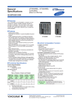
1.2 System Overview
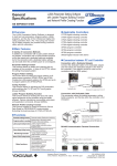
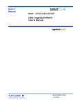
System Configuration
AddObserver
TCP/IP connection
Monitor server protocol
Data transfer
GateCONTROL
DAQLOGGER
Remote Monitor
TCP/IP connection
Monitor server protocol
Data transfer
RS-232
Ethernet
UT351-xA
Digital Indicating
Controller (with
Ethernet communications)
RS-485
Green Series
Digital Indicating Controllers
(with communication option)
VJET
Ethernet/RS-485
converter
RS-485
JUXTA VJ Series
Signal Conditioners
(with communication function)
ML2
RS-232C/RS-485
Converter
RS-485
JUXTA M series
Digital Alarm Configurators
(with communication function)
Up to 32 units
1-4
IM WX1-07E
Chapter 2
2.1
Operating
1
Running and Exiting GateCONTROL
Running the Software
2
Procedure
GateCONTROL > GateCONTROL.
Operating
1. From the Windows Start menu, choose Programs > YOKOGAWA DAQWORX >
3
GateCONTROL starts.
Index
Note
• When you start GateCONTROL it is restored to the same status that was active during the
previous session.
• If the program is closed while a process or service is running, the license will be considered
to be “in use.” If the message, “Invalid license number. Please reinstall.” appears when
restarting the program, it may indicate that the user is attempting to run a Gate program in
excess of the number of available licenses.
Exiting the Software
Procedure
1. Choose File > Exit from the menu bar, or click the X button at the right end of the
title bar.
IM WX1-07E
GateCONTROL closes.
2-1
2.2
Entering Environment Settings
This software includes an automatic model determination function, enabling automatic
acquisition of the connected devices' (temperature controllers and signal conditioners)
model names, tag information, and Modbus address when you enter the appropriate
serial port settings, IP addresses, and/or port numbers.
The following environment settings are entered.
• Serial port settings (when the communication mode is COM)
• Settings for the connected devices
• Data acquisition condition
• TCP/IP port settings for the monitor server
• Tag settings (enter the tag name and decimal place as needed)
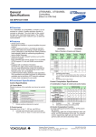
Serial Port Settings (When the Communication Mode is COM)
Procedure
1. Click the Serial Setting tab or choose View > Serial Setting from the menu bar.
The Serial Setting page in displayed.
Click to
select/clear
all rows
Click to display a
list of options
Drag to select
a range of items
Copies the setting
in the first item of
the selection to all
of the items in the
selection
Turns selected range ON/OFF collectively
Click to turn a single item ON/OFF
2. Turn ON the port numbers to be used, and set the baud rate, and parity.
2-2
Port number: ON (blue)/OFF (gray)
Baud rate: 4800, 9600, 19200, 38400
Parity: NONE, ODD, EVEN
IM WX1-07E
2.2 Entering Environment Settings
1
Settings for the Connected Devices
Register all devices that you will operate and from which you will acquire data.
Procedure
2
1. Click the Model tab or choose View > Model from the menu bar. The Model
When Ether communication is selected, clicking here displays a dialog box
for setting the IP address, port number, and Modbus address.
If COM1-COM9 is selected, a dialog box for setting the Modbus address appears.
Click to display a list box for selecting a communication port
Only enabled COM ports (specified in serial port settings) are displayed
Operating
Setting tab is displayed.
3
Index
Drag to select a range
of items
Copies the setting in the first item of the selection
to all of the items in the selection
2. Select the port to be used from the Communication Method list box.
If using an Ethernet port:
If using a COM port:
Ether
COM1–COM9
IP Address and Port Number (If Ethernet Is Selected for the Port)
3. Click an address. The Address Setting dialog box opens.
4. Enter the IP address (or host name) and port number.
IP address:Enter the IP address or host name set on the device to which
you wish to connect.
502
Port no.:
Modbus address: 1–9
(If you will perform automatic model determination, including for the
Modbus address, select Unknown.)
Note
The default port number for Modbus/TCP is 502. If no particular specification has been made
on the device, use this number.
IM WX1-07E
2-3
2.2 Entering Environment Settings
Modbus Address (for Ports Set to COM)
3. Click an address. The Address Selection dialog box opens.
4. Enter the Modbus address.
Modbus address: 1–99
If you will perform automatic model determination including for the Modbus
address, choose Unknown.
Automatic Model Determination
5. After specifying the communication methods and addresses, drag numbers to
specify the range for automatic model determination.
Automatic detection button
Drag to select a range for automatic model determination.
Clears the contents of
the status boxes.
6. Click the Automatic detection button at the bottom of the screen, click the
Automatic determination button in the toolbar, or choose Communication >
Automatic detection from the menu bar.
2-4
Model name, control mode, control output, option functions, and tag information
is automatically acquired. A loop back test is also executed at the same time.
If the test concludes without errors, a status of “OK” is displayed. (“Not OK” is
displayed if an abnormality occurred.)
IM WX1-07E
2.2 Entering Environment Settings
Note
and the UM33A as the UM331. The position proportional type UT35A, UT32A, UP55A and
UP35A are registered as the standard type UT351, UT321, UP550 and UP35A, respectively.
Heating / cooling type UT52A are registered as the Heating / cooling type UT551.
From the above, the one actually connected may differ from the one displayed on screen, as
follows.
Displayed
UT551
UT520
UT351
UT321
UP550
UM331
Actually connected model
UT55A, UT52A
UT52A
UT35A
UT32A
UP55A
UM33A
Data Acquisition Conditions
Procedure
1. Click the Scan Interval Setting tab or choose View > Scan Interval Setting from
the menu bar.
2. Set the scan interval, access timeout, retray use, and retry interval.
Scan interval:
0.5–60 s (or 500–60000 ms: initial value is 1000 ms)
Access timeout:
1–10 sec (or 1000–10000 ms: initial value is 5000 ms)
Retry Use:
Select whether or not to retry communications (ON/OFF).
Retry interval:
The interval between communication retries (30–3600 sec).
Note
• Retries are performed every scan interval at the specified retry interval until communication
is restored. Retries are also performed on instruments with which a communication error
occurred during the first communication. At the point that communication is restored, alarm
values and other information are retrieved from the connected temperature controllers or
signal conditioners and data is acquired.
• If Retry is turned OFF, you can retry the connection manually by clicking the Retry
Connection button on the Monitor/Status tab.
IM WX1-07E
2-5
1
2
Operating
• If you connect to an unsupported devices, “Unknown” is displayed for the model.
• It is not supported in the UP55A’s remote-mode operation. If the operation mode is
REMOTE, it is handled as LOCAL.
• If the result, model name, control mode, control output or option functions found by
automatic model determination differ, the tag list in the tag settings dialog box is initialized.
If the tag list was modified from the initial condition, the message, “OK to initialize tag list?”
is displayed. Click the Yes button to implement the search results and initialize the tag list.
Click the Cancel button to quit without applying the results of automatic model determination
to the model settings page.
・ The automatic model determination function registers the UT55A as the UT551, the UT52A
as the UT520, the UT35A as the UT351, the UT32A as the UT321, UP55A as the UP550
3
Index
2.2 Entering Environment Settings
TCP/IP Settings for the Monitor Server Port
The port number need not be changed unless desired.
Procedure
1. Choose File > Port No. from the menu bar.
The Port No. for the internal communication dialog box opens.
2. Enter the port number used to transfer data loaded from a connected device to
DAQLOGGER, Remote Monitor or AddObserver.
2-6
IM WX1-07E
2.2 Entering Environment Settings
1
Tag Settings
Procedure
1. Click the Detail Settings in the tag information column of the model you wish to
2
set in the Model Settings page.
Operating
3
Index
Click to Tag Setting dialog box
The Tag Setting dialog box opens.
One of the following tag names that was reserved is displayed.
PV1
PV2
SP1
SP2
OUT1
OUT2
HOUT1
HOUT2
COUT1
COUT2
A/M1
A/M2
C.A.M
R/L1
R/L2
SPNO
PIDNO1
PIDNO2
R/S
R/P/L
R/P1/P2
HOLD
PVE1
PVE2
PVE3
PVE4
PVE5
PVE6
PVE7
PVE8
TME1
TME2
TME3
TME4
TME5
TME6
TME7
TME8
TME9
TME10
TME11
TME12
TME13
TME14
TME15
TME16
PTNO
SEGNO
TIME
LSP/CAS
C.A.M1
C.A.M2
O/C
INPUT
ADVANCE
RUN
The tag settings include an input tab page and an output tab page.
Maximum number of input tags: 48
Maximum number of output tags: 32
IM WX1-07E
The active page is surrounded by a red frame. You can click anywhere on an
input/output tab page to move the red frame.
The list of registered tags is determined by the model, control mode, control
output, and option functions. Default tag list items displayed in gray cannot be
changed. Also, the default tag list cannot be deleted.
2-7
2.2 Entering Environment Settings
2. If you performed automatic model determination, the tag information acquired
from the connected devices is displayed.
If links are set, the edited contents are reflected on the linked channels.
Note
The UT55A, UT52A, UT35A, UT32A, UP55A and UP35A’s numbers of PID and SP groups
correspond to GateCONTROL’s PIDNO and SPNO span maximum values, respectively.
The numbers of PID and SP groups can be set separately on the UT55A and UT52A, but in
GateCONTROL’s Tag setting dialog box, the same SP group is used as the PIDNO and SPNO
span maximum.
On the UT35A and UT32A, you can set the number of PID groups and SP groups to a number
from 1 to 4, but the SPNO and PIDNO span maximum values are set to 4.
On the UP55A, you can set the number of PID groups to a number from 1 to 8, but the PIDNO1
and PIDNO2 span maximum values are set to 8. On the UP35A, you can set the number of
PID groups to a number from 1 to 4, but the PIDNO1 span maximum values are set to 4.
Editing the Input Tag Page
If the tag numbers are selected (blue),
they are displayed as tag numbers in
the Remote Monitor display groups
Select/clear all rows
The tab page to be set is
surrounded by a red frame
Delete input tags
Create input tags
Tag No.: Select to use (blue) or not use (gray) the selected tag numbers.
Register number: Shows the reference location of each register.
Setting range: 40001 to 49999
When Same on the Output tab page is ON (blue), the edited results
are reflected on the output tab page. Register numbers cannot be
duplicated (duplicate register numbers are allowed for the default
tags because the bit position of the referenced value is different).
Tag name:Specify using eight alphanumeric characters or fewer. In the Remote
Monitor, this is displayed as a channel name.
Tag names cannot be duplicated. Also, tags to which reserved tag
names have been added cannot be used.
Tag comment: Specify using sixteen alphanumeric characters or fewer.
In the Remote Monitor, this is displayed as a tag comment.
Decimal point:Set the decimal place to offset the register value. Select 0, 1, 2, 3, 4,
or 5. The initial values vary depending on the type of tag. If automatic
model determination is performed, the decimal point of the connected
device is displayed.
2-8
IM WX1-07E
2.2 Entering Environment Settings
Note
The tag number use/do not use settings are those of the ON/OFF display conditions of the
Remote Monitor.
The color setting is the display color of the Remote Monitor.
Editing the Output Tab Page
Select/clear all rows
Used as the Tag No. in AddObserver
The tab page to be set is surrounded by a red frame
Click to display the Tag selection dialog box
Click here (blue) to apply the edited register numbers to the input tab page,
or apply the edited register numbers to the input tab page.
Create output tags
Tag No.: Used as Tag No. in AddObserver
Registers:Same:When selected (ON), the output register number is applied to the input register number.
No.:Shows the location of the tag write register. However, since in the
case of SP there are multiple registers to be written, a register number
is not displayed. Register numbers cannot be duplicated.
Tag name: Specify using eight alphanumeric characters.
Used as Channel Name in AddObserver.
Tag names cannot be duplicated. Also, tags to which reserved tag
names have been added cannot be used.
Tag comment: Specify using sixteen alphanumeric characters or fewer.
In AddObserver, this is displayed as a tag comment.
IM WX1-07E
2-9
1
2
Operating
Span minimum/maximum:
Setting range:–1E16 to 1E16
The initial values vary depending on the type of tag. If automatic
model determination is performed, the setting value of the connected
device is displayed.
On the client side this is handled as the minimum/maximum of scale.
Units:Specify using six alphanumeric characters or fewer. The initial values
vary depending on the type of tag. If automatic model determination
is performed, the units set on the connected device are displayed.
Color:Click the colored part to open the Color Settings dialog box. An
arbitrary color can be entered.
Output link:Displayed in the format xx:tag name where xx is the output tag number.
Displays the tag for output that is linked to the input tag. This cannot
be changed.
Loaded value:Displays the tag name value loaded from the connected device when
the monitor is executed. “Error” is displayed if a communication error
occurs.
3
Index
2.2 Entering Environment Settings
Decimal point:Set the offsetting decimal place for writing to registers. Select 0, 1, 2, 3, 4,
or 5.
Span minimum/maximum:
Setting range: –1E9 to 1E9
If the value requested by AddObserver is outside of the span range, it is
not output.
Units: Specify using six alphanumeric characters or fewer.
Note
Registers 41280 (UTM, USM, UPM) and 41281 (SMP) of the UT520, UT550, UT551, UT750,
US1000, UP550, and UP750 cannot be written using the Modbus/RTU, Modbus/TCP protocol.
Please make note of this.
Input link: Displays and selects the tag for intput that is linked to the output tag.
Displayed in the format xx:tag name where xx is the input tag name.
When you click an input select button, the tag selection dialog box is
displayed.
Display the tag that links are not set of registered tags
of the input tab page
Links are not set
Input select button
Click here to display the Tag Selection dialog box.
Click here (blue) to apply the edited register numbers
in the input tag to the output tag
Output value: Specifies an output value for the output test.
Range: –1E9 to 1E9
Loaded value: The output register value is displayed after the output test.
If the output value is outside of the output span, “Out range” is
displayed. If a communication error occurs during output, “Com error”
is displayed.
2-10
IM WX1-07E
2.2 Entering Environment Settings
Tag Setting Execution Button
Duplicate register numbers and tag names are displayed in yellow.
IM WX1-07E
2-11
1
2
Operating
Insert input tags, insert output tags:
Insert a tag in the last line of the tag numbers.
Cannot be performed during testing.
Delete input tags, delete output tags:
Deletes the selected tag. If a tag is deleted, the tag numbers are
refreshed.
With deletion of input tags, the linked output tags are also deleted.
With deletion of output tags, the linked input tags are not deleted but the
link is cleared.
Default tags cannot be deleted.
Cannot be performed during testing.
Initialization:Added tags are all deleted, and the tag list returns to the default
condition.
OK:The settings in the tag settings dialog box are saved, and the dialog box
closes.
When testing, the settings are saved after the test is completed, and the
dialog box closes.
If register or tag names are duplicated, the dialog box below is
displayed.
3
Index
2.3
Saving and Restoring Environment Settings
Saving Environment Settings
Procedure
1. Click the Save button or choose File > Save from the menu bar.
Save button
The current settings are saved.
Restoring Environment Settings
This procedure clears all settings currently being entered and restores the most recently
saved settings.
Procedure
1. Choose File > Revert from the menu bar.
2-12
IM WX1-07E
2.4
1
Starting/Stopping Data Acquisition
2
Operating
When you start data acquisition using this software, data from connected devices
(temperature controllers and signal conditioners) is loaded, transferred to DAQLOGGER
or Remote Monitor, and output requests from AddObserver are written to connected
devices.
3
Note
The maximum number of DAQLOGGERs, Remote Monitors, or AddObservers that can be
connected at once is sixteen.
Index
Starting Data Acquisition
Procedure
1. Enter environment settings. (See section 2.2, “Entering Environment Settings.”)
Running from the Toolbar/Menu Bar
2. Click the Start button or choose Monitor > Start from the menu bar.
Data acquisition Start button
IM WX1-07E
The status of communication with the device is displayed in the Monitor/Status
tab under Communication status. Under Client status, the name of the connected
client, connection status, and the address of any disconnected DAQLOGGERs,
Remote Monitors, and AddObserver is displayed.
2-13
2.4 Starting/Stopping Data Acquisition
Starting (Executing) from the Monitor/Status Tab
2. Click the Start button on the Monitor/Status tab.
The name of connected clients and their communication statuses are displayed.
Maximum number of display of clients communication statuses is 48.
Start button
Click to start data acquisition
Stop button
Click to stop data acquisition
Turn ON (blue) to start data acquisition simultaneously
upon software startup
Starting the Software and Data Acquisition at the Same Time
3. When you turn ON “Start monitor at startup” in the Monitor/Status tab, data
acquisition starts at the same time that the software is started.
Stop data acquisition
Procedure
Stopping Acquisition from the Toolbar/Menu Bar
1. Click the Stop button or choose Monitor > Stop from the menu bar.
Nothing is displayed for the communication of connected devices.
Data acquisition Stop button
Stopping Acquisition from the Monitor/Status Tab
1. Click the Stop button on the Monitor/Status tab.
2-14
Nothing is displayed for the communication of connected devices.
IM WX1-07E
2.5
1
Performing Communication Tests of
Connected Devices
Before starting data acquisition, you can perform a loop back test, read test, and write
test between connected devices.
2
Operating
Performing the Loop Back Test
3
Using the loop back test you can check the specified communication method and
connection status with the device at the specified address.
Note
The loop back test can not be performed during data acquisition.
Index
Procedure
1. Click the Model tab or choose View > Model from the menu bar.
The Model tab is displayed.
Select/clear all items
Drag to select a range for collective setting
or the loop back test
Result appears
OK: Normal
Not OK: No response
Click to clear the
contents of the status
2. Drag to select the numbers on which you wish to perform the loop back test.
3. Click the Loop Back Test button.
The result appears in the status column.
OK: Normal
Not OK: No response
Note
• If the result is Not OK, check whether the communication settings of the software and target
device match.
• If the loop back test will be performed on multiple devices, individual tests are performed
even if a communication error occurs part way through.
IM WX1-07E
2-15
2.5 Performing Communication Tests of Connected Devices
Performing Read and Write Tests
You can check the data of the registers specified in the input tab page (monitor
execution) by performing a read test.
Also, you can perform a write test to the registers specified in the output tab page during
monitor execution.
Note
The Read and Write tests cannot be performed during data acquisition.
Procedure
Performing a Read Test
1. Click the Detail Settings button in the Model Settings tab page of the model on
whicih you wish to perform the read test.
The Tag Setting dialog box opens.
Click to display the Tag Settings dialog box
Monitor execution
results
Output test
results
Specifies the output
values during the
output test
Drag to select the tag on which
to perform the output test
Monitor start button
Monitor Stop and Output Test Buttons
2. Click the Start monitor button.
2-16
The value of each tag from the instrument is loaded, and displayed in the loaded
value column of the input tab sheet.
To quit monitor execution, proceed to step 6.
IM WX1-07E
2.5 Performing Communication Tests of Connected Devices
1
Performing a Write Test
3. Specify the Output Values of the tags on which you wish to perform the output
test in the output tab page.
2
4. Select the tags on which to perform the output test
5. Click the Output Test button.
The output values are written to registers, then the values are acquired from the
write registers and the loaded results are displayed in the loaded value column in
the output tab page.
Operating
3
Stopping the Read Test
6. Click the Stop monitor button.
IM WX1-07E
Index
The Read Test is concluded.
2-17
2.6
Checking the Client Connection Status and
Communication Status of Connected Instruments,
and Reconnecting Connected Instruments
Checking the Client Connection Status and Communication Status of Connected
Instruments
Procedure
Checking the Connection Status
1. Click the Monitor/Status tab or choose View > Monitor/Status from the menu
bar. The Monitor/Status tab is displayed.
The client connection status and communication status of connected devices is
displayed.
Indicator for the communication
status with the connected device
Green: Normal (comm. open)
Red: Communication error
Yellow: Data dropout occurred
and communication is retried
(communication paused)
No display: Communication error
(comm. paused)
Double-click to display the Error
Indicator dialog box
Displays the names of connected clients
Note
• If the communication status of a connected device is red, check whether a model, control
mode, control output, or option in the Model Setting tab have the same settings as the
connected device, and whether the communication method is correct.
• Data acquisition cannot be performed when the status is red.
2-18
IM WX1-07E
2.6 Checking the Client Connection Status and Communication Status of Connected
1
Viewing Error Detail
2. Double-click the status indicator under Communication Status. The Error
Indicator dialog box opens.
Up to 100 of the most recent errors are displayed for each connection.
Errors are displayed in the order date/time of occurrence, error number, error
contents, affected number, and affected system number.
2
Operating
3
Index
See section 3.4 for error messages.
Note
If a connected instrument experiences an error during communications, attempts are made to
restore communications at the specified retry interval. If communication cannot be restored,
the status indicator turns red. Retries are performed until communication is restored. To start
communication manually, click the Retry Connection button.
Reconnecting Connected Instruments
1. Select the instrument to reconnect.
2. Click the Retry Connection button.
IM WX1-07E
Communication with the selected device is reopened.
2-19
2.7
Viewing Version Information
Procedure
1. Click the About button or choose Help > About from the menu bar.
The Version dialog box opens.
Version
Company name
User name
License number
2-20
IM WX1-07E
Chapter 3
3.1
Functions
1
Modbus Communication Device Settings
Port number
Baud rate
Parity
• Settings for the Connected Devices (Temperature Controllers and Signal
conditioners)
Serial Communications
• Communication protocol
• Baud rate
• Parity
• Stop bit
• Data length
• Communication Address
Ethernet Communications
• IP address
• Subnet mask
• Default gateway
Enter communication parameters on devices connected to GateCONTROL in advance.
For instructions, see the user’s manual of the connected device.
Note
The PC is connected to the instrument via an RS-232C/RS-485 converter. The connection can
be made using a 4-wire or 2-method. When using the 2-wire method, disable echo back on the
Converter.
Settings for Connected Modbus Devices
Enter settings on the connected devices as follows.
Baud rate
Parity
Stop bit
Data length
Communication protocol
IM WX1-07E
Green Series
UT1000 Series
UTAdvanced Series
4800, 9600, 19200 or 38400
ODD, EVEN, or NONE
1
1
8
8
8
4
3
Index
• Serial Port Settings (as Needed)
Setting
2
Functions
The default tag list in the Tag Settings dialog box that is displayed when you click the
detail settings in the Model Settings tab determines the model, control mode, control
output, and option function contents of the Model Settings tab.
The following describes the meanings of each tag that may appear in the Tag Settings
dialog box.
Also, the tag names listed here are reserved. Arbitrarily added tags cannot be used.
therefore the same serial and model settings as the connected device must be set on
GateCONTROL.
US100
VJ Series
M Series
1
8
1
1
8
MODBUS, RTU mode
1
8
4
3-1
3.2
Meanings of Tags of Connected Devices
The default tag list in the Tag Settings dialog box that is displayed when you click the
detail settings in the Model Settings tab determines the model, control mode, control
output, and option function contents of the Model Settings tab.
The following describes the meanings of each tag that may appear in the Tag Settings
dialog box.
Also, the tag names listed here are reserved. Arbitrarily added tags cannot be used.
Tag Name
PV1
PTNO
Meaning
Measurement input value on loop 1, or the measurement input value. The
error status and alarm status of PV1 or the measurement input value is
added.
(See section 3.3 for information on handling error and alarm statuses.)
Measurement input value on loop 2. The error status and alarm status of PV2
is added.
Target setting value used on loop 1. SP1 related alarm statuses are added.
Target setting value used on loop 2. SP2 related alarm statuses are added.
Control output value on loop 1. Control output value on loop 1. OUT1 related
alarm statuses are added.
Control output value on loop 2. Control output value on loop 2. OUT2 related
alarm statuses are added.
For heating/cooling control on loop 1, or the control output value for heating.
HOUT1 related alarm statuses are added.
For heating/cooling control on loop 2, or the control output value for heating.
HOUT2 related alarm statuses are added.
For heating/cooling control on loop 1, or the control output value for cooling.
COUT1 related alarm statuses are added.
For heating/cooling control on loop 2, or the control output value for cooling.
COUT2 related alarm statuses are added.
Auto/manual mode for loop 1
0: AUTO (automatic) mode, 1: MAN (manual) mode
Auto/manual mode for loop 2
0: AUTO (automatic) mode, 1: MAN (manual) mode
Switch between manual/automatic/cascade
0: AUTO (automatic) mode, 1: MAN (manual) mode, 2: CAS (cascade) mode
Remote/local mode on loop 1.
0: Local, 1: Remote
Remote/local mode on loop 2.
0: Local, 1: Remote
Target setting value number currently used
PID number used on loop 1
PID number used on loop 2
Running/Stopped status
0: Running, 1: Stopped
Program run reset/program mode
0: Program operation reset, 1: Program operation, 2: Local operation
Program run reset/program mode
1: Program operation reset, 2: Program 1 operation, 3: Program 2 operation
Program operation pause mode
0: Program operation, 1: Program operation pause
PV event status. x is the event number
0: Event OFF, 1: Event ON
Time event status. x is the event number
0: Event OFF, 1: Event ON
Number of currently operating program pattern
SEGNO
Number of currently operating segment
PV2
SP1
SP2
OUT1
OUT2
HOUT1
HOUT2
COUT1
COUT2
A/M1
A/M2
C.A.M
R/L1
R/L2
SPNO
PIDNO1
PIDNO2
R/S
R/P/L
R/P1/P2
HOLD
PVEx
TMEx
(Cont. on next page.)
3-2
IM WX1-07E
3.2 Meanings of Tags of Connected Devices
Tag Name
TIME
LSP/CAS
C.A.M1
C.A.M2
O/C
ADVANCE
RUN
IM WX1-07E
3-3
1
2
3
Functions
INPUT
Meaning
Remaining time of currently operating segment, or time elapsed during WAIT
The units are seconds.
Local/Cascade mode
0: CAS (cascade) mode, 1: LSP (local) mode
Cascade/auto/manual mode for loop 1
0: AUTO (automatic) mode, 1: MAN (manual) mode, 2: CAS (cascade) mode
Cascade/auto/manual mode for loop 2
0: AUTO (automatic) mode, 1: MAN (manual) mode, 2: CAS (cascade) mode
CLOSE/OPEN mode
0: CLOSE mode, 1: OPEN mode
Input value. The error status and alarm status are added.
(See specific items for information on handling error and alarm statuses.)
Segment forced transition
0: End of forced transition or not executed, 1: Segment forced transition
Program run/stop status
0: Stopped, 1: Running
Index
3.3
Details on Functions
Time Out Operation
When reading tag data, after sending a register value request message to the Modbus
device, if the message is not received within the specified time out time that tag is
considered to have timed out. If Use Retry is set to ON, for tags on which a timeout
occurred, retries are attempted starting from the next acquisition interval at the specified
retry interval until communication is restored.
If Retry is turned OFF, a retry is not performed on the tag on which a timeout occurred,
and data reading is not performed for that tag thereafter.
To reopen communications after loading stops, choose the target device for
communication in the Acquisition/Status tab, then click the Reconnect button.
Note
Using GateCONTROL, data can be acquired concurrently on each COM port. Therefore data is
logged more efficiently when connecting each device to a separate port rather than connecting
several devices to a single port.
3-4
IM WX1-07E
3.3 Details on Functions
1
Error Status
The following shows the error statuses supported by each model. Also, the statuses are
modified as shown before transfer to DAQLOGGER and Remote Monitor.
2
UTAdvanced Series, Green Series, UT100 Series, US1000
Data Display after Change
ILLEGAL
ILLEGAL
+OVER
-OVER
ILLEGAL
ILLEGAL
+OVER
-OVER
3
Functions
Device Data Status
PV1 A/D converter error
PV1 RJC error
PV1 overscale
PV1 underscale
PV2 A/D converter error
PV2 RJC error
PV2 overscale
PV2 underscale
Index
VJ Series
Device Data Status
EEP error
EEP sum error
Low cut status
A/D burnout
RJC error
Data Display after Change
ILLEGAL
ILLEGAL
-OVER
ILLEGAL
ILLEGAL
M Series
Device Data Status
Low cut status
Input over
Input under
EEP sum error
Parameter error
RJC error
EEP error
Data Display after Change
-OVER
+OVER
-OVER
ILLEGAL
ILLEGAL
ILLEGAL
ILLEGAL
Note
•
•
•
•
IM WX1-07E
When connected to a UT52A or UT55A, if a PV1 A/D converter error occurs, the PV1 value
is displayed instead of ILLEGAL.
When connected to a UT52A or UT55A, if a PV2 A/D converter error or a PV2 RJC error occurs, the PV2 value is displayed instead of ILLEGAL.
When connected to a UT32A, UT35A, UT52A, or UT55A, if a PV1 RJC error occurs, the PV1 value is displayed instead of ILLEGAL.
A/D converter and RJC errors (PV1 and PV2 ) of the UP55A are not supported.
3-5
3.3 Details on Functions
Processing Alarm Statuses
Each model’s alarm types are changed as follows before being sent to DAQLOGGER
and Remote Monitor.
Alarm Type on Device Side
PV high limit
PV low limit
Deviation high limit
Deviation how limit
De-energized on deviation high limit
alarm
De-energized on deviation low limit
alarm
Deviation high and low limit
Deviation within high and low limit
De-energized on PV high limit
De-energized on PV low limit
PV high limit
(with idle mode)
PV low limit
(with idle mode)
Deviation high limit
(with idle mode)
Deviation low limit (with idle mode)
De-energize on deviation high limit
alarm (with idle mode)
De-energize on deviation low limit alarm
(with idle mode)
Deviation high and low limit
(with idle mode)
Deviation within high and low limit
(with idle mode)
De-energized on PV high limit
(with idle mode)
De-energized on PV low limit
(with idle mode)
Timer function upward (hour/minute)
Timer function downward (hour/minute)
Timer function upward (minute/second)
Timer function downward
(minute/second)
Sensor grounding alarm
Fault diagnosis output
FAIL output
Timer function
De-energized on timer function
Heater burnout alarm 1
Heater burnout alarm 2
Heater burnout
SP high limit
SP low limit
Output high limit
Output low limit
PV velocity alarm
PV velocity alarm passive
Self-diagnostic alarm
Self-diagnostic alarm passive
FAIL passive
Deviation high limit for target setpoint
Deviation low limit for target setpoint
3-6
Alarm Type after Change
PV
PV high limit [H]
PV low limit [L]
Deviation high limit [DH]
Deviation low limit [DL]
Deviation high limit [DH]
SP
—
—
—
—
—
OUT, HOUT, COUT
—
—
—
—
—
Deviation low limit [DL]
—
—
Other [ETC]
Other [ETC]
PV high limit [H]
PV low limit [L]
PV high limit [H]
—
—
—
—
—
—
—
—
—
—
PV low limit [L]
—
—
Deviation high limit [DH]
—
—
Deviation low limit [DL]
Deviation high limit [DH]
—
—
—
—
Deviation low limit [DL]
—
—
Other [ETC]
—
—
Other [ETC]
—
—
PV high limit [H]
—
—
PV low limit [L]
—
—
Other [ETC]
Other [ETC]
Other [ETC]
Other [ETC]
—
—
—
—
—
—
—
—
Other [ETC]
Other [ETC]
Other [ETC]
Other [ETC]
Other [ETC]
Other [ETC]
Other [ETC]
Other [ETC]
Other [ETC]
Other [ETC]
Other [ETC]
Other [ETC]
Other [ETC]
Other [ETC]
Other [ETC]
Other [ETC]
Other [ETC]
Other [ETC]
Other [ETC]
—
—
—
—
—
—
—
—
SP high limit [H]
SP low limit [L]
—
—
—
—
—
—
—
Deviation high limit [DH]
Deviation low limit [DL]
—
—
—
—
—
—
—
—
Output high limit [H]
Output low limit [L]
—
—
—
—
—
—
—
(cont. on next page)
IM WX1-07E
3.3 Details on Functions
Alarm Type on Device Side
SP
Deviation high limit [DH]
OUT, HOUT, COUT
—
Other [ETC]
Deviation low limit [DL]
—
Other [ETC]
Other [ETC]
—
Other [ETC]
Other [ETC]
—
Other [ETC]
Deviation high limit [DH]
—
Other [ETC]
Deviation low limit [DL]
—
Other [ETC]
Deviation high limit [DH]
—
Other [ETC]
Deviation low limit [DL]
—
Other [ETC]
Other [ETC]
—
Other [ETC]
Other [ETC]
—
Other [ETC]
Other [ETC]
Other [ETC]
Other [ETC]
Other [ETC]
Other [ETC]
Other [ETC]
Other [ETC]
Other [ETC]
Other [ETC]
Other [ETC]
Other [ETC]
Other [ETC]
Other [ETC]
SP high limit [H]
SP low limit [L]
—
—
—
—
—
—
—
—
—
—
—
—
—
—
Output high limit [H]
Output low limit [L]
—
—
—
—
—
—
—
—
—
—
1
2
3
Functions
De-energized on deviation high limit
alarm for target setpoint
De-energized on deviation low limit
alarm for target setpoint
De-energized on deviation high and low
limits for target setpoint
Deviation within high and low limits for
target setpoint
Deviation high limit with stand-by
actions for setpoint
Deviation low limit with stand-by actions
for setpoint
De-energized on deviation high limit
alarm with stand-by actions for target
setpoint
De-energized on deviation low limit
alarm with stand-by actions for target
setpoint
Deviation high or low limit with stand-by
actions for setpoint
Deviation within high and low limits with
stand-by actions for target setpoint
Target SP high limit
Target SP low limit
Cooling-side control output high limit
Cooling-side control output low limit
Analog input PV high limit
Analog input PV low limit
Analog input RSP high limit
Analog input RSP low limit
Analog input AIN2 high limit
Analog input AIN2 low limit
Analog input AIN4 high limit
Analog input AIN4 low limit
Feedback input high limit
Feedback input low limit
Alarm Type after Change
PV
Other [ETC]
Index
Displayed in brackets ([ ]) on DAQLOGGER and Remote Monitor.
Furthermore, for the VJ series, all alarm types are Other [ETC].
Alarm types are loaded from each connected device upon start of acquisition by
GateCONTROL. Even if alarm types are changed on the connected device after
acquisition starts, the alarm types valid upon start of acquisition are used.
The number of UT551 and UT520 alarms is four (fixed). To ensure compatibility, also set
the number of UT55A and UT52A alarms to four.
The number of UT351 and UT321 alarms is three (fixed). To ensure compatibility, also
set the number of UT35A and UT32A alarms to three.
The number of UP550 and UM331 alarms is four (fixed). To ensure compatibility, also set
the number of UP55A and UM33A alarms to four.
The number of UP35A alarms is two (fixed).
IM WX1-07E
3-7
3.3 Details on Functions
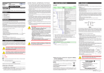
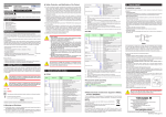
Output Processing
Output request from client
Storage buffer for
output request
Checked at 1 second intervals
Acquisition executed
Output executed
Instrument
Function
• The output request from the client is stored in the output request storage buffer.
• The output request storage buffer is checked for an output execution every second,
and output is executed on the instrument if an output request is found. Then, the
output request storage buffer is cleared.
• Output request storage buffer is set to hold the most recent value, so if multiple
writings to the same tag occur during the confirmation interval, the written value
becomes the most recent one.
• An instrument is either outputting or acquiring, and acquisition execution is put on
hold until output execution is finished, and vice versa. Therefore, acquisition or output
execution may be delayed.
Also, time may be required for output execution. If so, it can occur more slowly than
the one-second confirmation interval.
Writing of the SP Value
During output execution, SPNO is acquired from the instrument. SP value output is
executed on the register corresponding to this SPNO.
3-8
IM WX1-07E
3.4
Notes When Performing Communications with
Software on Other PCs
Communications with DAQLOGGER
Communications with DAQLOGGER Client Package
Check the port number (initial value is 50299) and system number set in GateCONTROL,
then reconnect. The logic behind the system numbers is the same as that for
DAQLOGGER.
GateCONTROL Settings
Set the same serial and model settings as the connected device on GateCONTROL.
IM WX1-07E
3-9
2
3
Functions
• When performing communications with DAQLOGGER, set the IP address of
the device with which DAQLOGGER will connect on the address of the PC that
GateCONTROL is operating, then execute automatic model determination.
• On DAQLOGGER, all devices connected to GateCONTROL (temperature controllers
and signal conditioners) are considered a single system. Therefore, the following
should be noted.
• DAQLOGGER’s automatic model determination determines only the lowestnumbered device if multiple devices are connected to GateCONTROL (temperature
controllers and signal conditioners). For determination of the other devices, specify
the port number and system number (a number that is 1 less than the number
in the GateCONTROL’s Model Settings tab) in the DAQLOGGER settings, then
execute the automatic model determination function.
• When connecting all devices connected to GateCONTROL to DAQLOGGER
as one system, specify “No system number” in the address setting screen, then
execute automatic model determination.
1
Index
3.5
Error Messages and Corrective Actions
A message (such as an error message) may appear during operation. The following
describes the meanings of the messages and their corrective actions.
Error
Code
E211
E212
Description
Cannot write to the file.
Cannot read file.
E213
Cannot open the file.
E501
Invalid license number. Please reinstall.
E1010
Execution failed.
Corrective Action
Confirm that the disc capacity and file system are correct.
Confirm that a file exists, that the software supports it, and
whether the file system is correct.
Confirm that a file exists, that the software supports it, and
whether the file system is correct.
With the Gate series, the number of licenses purchased is the
limit for the number of programs run at the same time. Reinstall
the software.
Confirm that the file is not corrupt. If this error appears repeatedly,
reinstall the software.
Message
Code
M1210
Description
Save the setting changes and try again.
Messages during (When Executing) Data Acquisition
Code
W[631]
Description
Data Lack
E[674]
Communication error
E[675]
Communication time out
E[800]
CRC check error
E[801]
Invalid handle
E[802]
Error respond
W[880]
W[881]
Do not specify communication port
Current connecting model
configuration is mismatch!
The model is:
Retry connection
W[884]
3-10
Cause/Corrective Actions
Data was unexpectedly lost. Reduce the number of acquired data
points or connected instruments, or lengthen the scan interval.
Communication Errors
Check whether the power to the connected measuring
instruments with which you wish to open communications is ON,
and whether the cables are connected correctly. Also check the
following.
• For Ethernet
Is the address correct, is the TCP/IP protocol installed in
Windows, and is the Ethernet card installed correctly?
• For RS-232 and RS-422-A
Are the baud rate, port numbers (COM1–COM9), and addresses
(RS422) correct? Is the PC serial port valid? Is the cable type
correct?
Communication timeout
Same as E[674].
CRC check error
A CRC error was detected. Check the communication status.
Failed to get communication handle.
Check the communication status.
Invalid data received.
Check the communication status.
Specify the communication parameters.
Change the parameters for the main unit.
Connection recovered.
IM WX1-07E
Index
1
Index
A
W
alarm statuses....................................................................... 3-6
automatic model determination............................................. 2-4
write tests............................................................................ 2-16
C
3
client connection status....................................................... 2-18
communication device settings............................................. 3-1
E
Index
Index
error messages................................................................... 3-10
error status............................................................................ 3-5
exiting the software............................................................... 2-1
H
hardware requirements......................................................... 1-3
I
IP address............................................................................. 2-3
L
loop back test...................................................................... 2-15
M
meanings of tags................................................................... 3-2
Modbus address.................................................................... 2-4
O
output processing.................................................................. 3-8
overview................................................................................ 1-1
P
port number.................................................................... 2-3, 2-6
R
read tests............................................................................. 2-16
running the software.............................................................. 2-1
S
saving dnvironment settings................................................ 2-12
serial port settings................................................................. 2-2
server port............................................................................. 2-6
settings for connected Modbus cevices................................ 3-1
software license......................................................................... ii
software requirements........................................................... 1-3
starting data acquisition....................................................... 2-13
system................................................................................... 1-2
system configuration............................................................. 1-4
T
tag settings............................................................................ 2-7
TCP/IP settings...................................................................... 2-6
time out operation.................................................................. 3-4
V
version information.............................................................. 2-20
IM WX1-07E
2
Index-1