1
Air Circuit Breakers BT2 Series
5-7, Nihonbashi Odemma-cho, Chuo-ku, Tokyo, 103-0011, Japan
URL http://www.fujielectric.co.jp/fcs/eng
Information in this catalog is subject to change without notice.
Printed in Japan 2012-1 Ed5 FOLS EEH606
EEH606
Air Circuit Breakers
BT2 Series 1600 to 6300A
Contents
Features ..................................................................... 3
Type number nomenclature......................................... 6
Specifications.............................................................. 7
Appearance................................................................. 8
Intelligent controller (OCR).......................................... 9
Communication.......................................................... 14
Characteristics curve................................................. 16
Accessories............................................................... 23
Technical data............................................................ 28
Dimensions and mounting......................................... 30
Wiring diagram.......................................................... 54
Ordering form............................................................ 62
Ordering notice.......................................................... 63
Air Circuit Breakers
BT2 series
Features
Selection guide
Series
BT2 series
Frame size
No. of poles
Installation
1600, 2000, 2500, 4000, 6300
3, 4
Available
Available
Manual spring or motor spring
Shunt trip, Under-voltage trip
Long time delay, Short time delay, Instantaneous, Ground fault, etc.
Closing Mechanism
Tripping Mechanism
Protection function
Fixed
Draw-out
Breaking Capacity
Icu is equal to Ics up to 120kA at maximum and Icw is up to 100kA at maximum under 400VAC distribution.
3
W1-
CW2-2000断 路 器 , 可 直 接 替 换 原 CW1-
CW2-2000 can directly substitute for CW1-
Air2000断路器,无需改变母排和柜门的开孔尺寸。
Circuit Breakers
BT2 series
Features
2000 without changing copper bar and aperture
dimensions on the panel sheet.
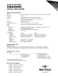
Compact size
BT2 series, Air Circuit Breakers, have five framesize and four
physical dimension sizes.
Ampere
1600
frame
Outstanding
Appearance
2000
2500
4000
6300
upgrade performance
CW2-2000 can directly substitute for CW1-
寸。
2000 without changing copper bar and aperture
dimensions
on the panel sheet.
简便安装、节约成本
CW2系列断路器具有更简单的安装方式,可以
简便实现
水平连接
垂直连接
混合连接
Width
248mm
347mm
401mm
Simply
installed、cost-saving
CW2 Series Circuit Breakers can be simply
installed as follows:
Installation
Horizontal connection
The bus bar terminal of the BT2 series, Air Circuit Breakers, can
Vertical
connection
be simply installed
as follows:
• Horizontal connection
Composite connection
767mm
Safety performance
BT2 series, Air Circuit Breakers, are reliable by the following
aspects:
• Reliable assurance of the three positions:
Connected
Test
Separated
by the locked and automatically unlocked mechanism at the
draw-out socket.
• Vertical connection
• Composite connection
先进可靠的安全性能
CW2系列断路器具有可靠的:
抽屉座三位置锁定和自动解锁装置,安全
确认“连接”、“试验”、“分离”三个位置。
Advanced and reliable safety performance
CW2 Series Circuit Breakers are reliable by the
following aspects:
Reliable assurance of the three positions:
connected、 test、 separated by the locked and
automatically unlocked mechanism at the draw-out
socket.
,可以
simply
Clear indication of ready-for-switching-on to ensure safe
manipulation and reliable operation.
Indication of ready-forswitching-on:"ok"
5
,安全
置。
by the
More reliable safety protection with seconday terminals of
protection grade IP30
sitions:
d and
aw-out
4
Air Circuit Breakers
BT2 series
Features
Protection and selection
BT2 Series, Air Circuit Breakers, can implement selective
interlock of ZSI Region to ensure comprehensive selection
of various protection and reduce the copper bar's bearing of
thermodynamic.
21
22
23
24
21
22
23
24
21
22
23
24
21
22
23
24
Intelligent controller (OCR)
Selecting OCR's, it can be classified into six types
Type
L25
Option
M25
Standard
M26
Option
H26
Option
P25
Option
P26
Option
Pic
L25 Intelligent Controller
M25 Intelligent Controller
M26 Intelligent Controller
H26 Intelligent Controller
P25 Intelligent Controller
P26 Intelligent Controller
Display/setting Light columnar indication LED digtal indication LED digtal indication LED digtal indication LCD indication
Dial setting by knob Consecutive
Consecutive
Consecutive
Consecutive
parameter setting
parameter setting parameter setting
parameter setting
Protection/
t
t
t tt
t tt
t tt
t tt
function
I II
I II
I II
t tt
I I II
t tt
I II
LCD indication
Consecutive
parameter setting
t
t
I
I
t
t
I II
I
5
Air Circuit Breakers
BT2 series
Type number nomenclature
Type number nomenclature
BT2-2500P / 32500E
Basic type
Frame size
1600, 2000, 2500, 4000, 6300
Installation
P: Fixed type
X: Draw-out type
Number of poles
3: 3 poles
4: 4 poles
Rated current
1600AF: 0200, 0400, 0630, 0800, 1000, 1250, 1600
2000AF: 0630, 0800, 1000, 1250, 1600, 2000
2500AF: 1250, 1600, 2000, 2500
4000AF: 2000, 25000, 2900, 3200, 3600, 4000
6300AF: 4000, 5000, 6300
CE version
OCR type or Additional accessories
• OCR type (note: M25 is standard), See page 9
Type
Code
Remarks
L25
L5A
M25
– (None)
H26
H6A
P25
P5A
P5B
w harmonic analysis function
P5C
w communication function
P5D
w alarm of current-imbalance
P26
P6A
P6B
w harmonic analysis function
P6C
w communication function
P6D
w alarm of current-imbalance
• Accessories
Type
LED indicator of Voltage
Load-monitoring function
ZSI function
(Zone selective interlock function)
Under voltage release
Switching OFF lock device
Mechanical interlock device
(Two sets of ACB's)
Mechanical interlock device
(Three sets of ACB's)
Current transformer for neutral
line N connected externally
Electrical mechanism for the
indication of draw out socket's position
Separator plate between phases
Electrical module for indication
of ready-for-switching-on
"Button" Locking device
Counter
Communication function choice
of accessories
DC power supply module
AC power supply module
Automatic transfer switch (ATS)
(included automatic controller,
connector and 1.8m cable)
6
Code
C1
C2
C3
Remarks
R1
R2
Q1
Q2
Q3
MW1
MB1
MW2
MB2
MB3
MB4
N1
N1
N2
N3
N4
N6
D1
Instananeous
Time delay
One lock and one key
Two lock and one key
Three lock and two key
Steel lock interlock
Link rod interlock (0,6m)
Cable type interlock
Pattern one of rod interlock
Pattern two of rod interlock
Pattern three of rod interlock
1600AF L・M・H Controller
1600AF P Controller
2000AF
2500AF
4000AF
6300AF
B3
B4
RFS
3P
4P
L
CM
S1
S2
S3
S4
PD1
PD2
PD3
PA1
PA2
AS1
AS2
AS3
Components of draw-out socket communication module
Ready-for-switching-on signal
Under-voltage signal
Fault-trip signal
24VDC
110VDC
220VDC
230VAC
400VAC
R type
S type
F type
Air Circuit Breakers
BT2 series
Specifications
Specifications
Frame size
Basic type
No. of poles
Rated current (A)
1600A
BT2-1600
3
4
200, 400, 630, 800,
1000, 1250, 1600
Rated current of the neutral pole 100% In
(IN)
Rated insulation voltage (Ui)
1000
Rated operational volage (Ue)
690
Rated ultimate short-circuit 690VAC *1 40
breaking capacity (Icu kA, 400VAC 50
sym)
Rated service short-circuit 690VAC *1 25
breaking capacity (Ics kA, 400VAC 50
sym)
Rated making current 690VAC *1 84
(kA, peak)
400VAC 105
Rated short time withstand 690VAC *1 25 (0.5s)
current (Icw) (kA, rms)
400VAC 42 (0.5s)
Rated impulse withstand voltage 12
(Uimp) (kV)
Installations
Fixed
P
Draw-out X
Main circuit terminal connection
Fixed
Horizontal
Vertical
Draw-out Horizontal
Vertical
Dimensions
Fixed
W
254
324
H
320
320
D
197
197
Draw-out W
248
318
H
351.5
351.5
D
297
297
2000A
BT2-2000
3
4
630, 800, 1000,
1250, 1600, 2000
100% In
2500A
BT2-2500
3
4
1250, 1600, 2000,
2500
100% In
4000A
BT2-4000
3
4
2000, 2500, 2900,
3200, 3600, 4000
100% In
6300A
BT2-6300
3
4
4000, 5000, 6300
1000
690
50
80
1000
690
50
85
1000
690
75
100
1000
690
85
120
50
80
50
85
75
100
85
120
105
176
40 (1s)
60 (1s)
12
105
187
50 (1s)
65 (1s)
12
165
220
75 (1s)
85 (1s)
12
187
264
85 (1s)
100 (1s)
12
362
395
290
347
438
390
457
395
290
442
438
390
–
–
362
395
290
347
438
390
457
395
290
442
438
390
414
395
290
401
438
395
527
395
290
514
438
395
100% In
782
395
290
767
475.5
395
1008
395
290
993
475.5
395
Note: *1 Cannot be used for an IT distribution system.
Available
7
Air Circuit Breakers
BT2 series
Appearance
Appearance
• Fixed
• Draw-out
6
6
7
7
5
9
4
4
10
3
3
11
2
12
2
1
8
9
10
11
12
1
13
14
15
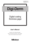
<Common>
1: Name plate
2: Indications of energy-storage and energy-release
3: ON button
4: Manual energy-storage handle
5: Brand
6: Terminals of sencondary circuit (fixed)
7: Off lock mechanism
8: Release indication and resetting button
9: Inteligent controller (OCR)
10:OFF button
11:Indications of "ON" and "OFF"
12:Indication of ready-for-switching-on ("OK")
• Draw-out cradle
The cradle has the back plate for isolating the copper bar of
the main circuit, which take the role of safety protection when
the ACB is drawn out.
21
22
20
19
23
18
24
18:Installation hole
19:Safety back plate
20:Wiring terminals of secondary circuit
21:Side plate
22:Copper bar of the main cirucit
23:Draw-out socket
24:Earthing point at draw-out socket
8
5
8
17
16
<For Draw-out>
13:"Unlock button" of the three positions
("Separated", "test" and "connected") *1,2
14:Safety padlock mechanism
15:Racking shaft operating hole
16:Racking shaft storage hole
17:Indications of the three position
("Separated", "test" and "connected")
Note: *1 "Separated": Indicates that main circuit and secondary circuit are both in
isolation."Test": Indicates that main circuit is in isolation and secondary
circuit is in connection."Connected": Indicates that main circuit and
secondary circuit are both in connection.
*2 The ACB can be automatically locked (racking shaft can not be turned
at the point) when its main part is at the position of "separated","test"
or "connected" by turning the racking shaft, and can be unlocked by
pushing "unlock button" to the left side.
Air Circuit Breakers
BT2 series
Intelligent controller
Intelligent controller (OCR)
Selecting OCR's, it can be classified into six types
Type
L25
Option
Overcurrent protection
(Long-time, Short-time, insantaneous)
Ground-fault protection
Load monitor function
Indication
Power, electric energy, power-factor, frequency indication
Alarm function (pre-trip alarm, overload alarm)
Test function
Contact Welding indication
Self-diagnosis function
MCR funciton
Fault-memory funciton
Current-imbalance indication
Thermo-analogue function
Harmonic analysis function
ZSI function
Communication function
Note:
Reprensents fundamental functions,
M25
Standard
–
–
–
Light Columnar LED
–
–
–
–
M26
Option
H26
Option
P25
Option
P26
Option
–
LED
LED
–
–
–
–
–
–
–
–
–
LCD
–
LCD
–
–
–
–
–
–
–
–
–
–
Represents selective functions, – Represent no such functions
Function
Over-current protection
• The over-current protection is composed of phase and neutral line
protection (Four pole breaker and three pole breaker with current
transformer linking externally to neutral N) from over-current.
• The parameters of current and time of phase line over-current
protection can be set by the company in terms of the requirements
of users (can be set by customers themselves); the parameters of
current and time of neutral line over-current protection will be set
according to the setting of the phase line, all these mainly divided
into the following two situations:
Three pole breaker with the neutral connected eaternally
• To type L25, M26, H26 intelligent controller, when ordering the goods
the neutral line setting current customers should have to confirm the
protecting data, it has two type of 50%In and 100%In.
• To type P25, P26 intelligent controller, the customers can setup
into four types from menu:turn off, 50%In, 100%In, 200%In. When
200%In neutral line protecting (if it has a high triple frequency
harmonic), the neutral line cross section should be double leg of a
circuit cross section in the electrical power distribution system. But to
BT2-6300 three circuit breaker, there is no neutral line protecting.
Four pole breaker
• To type L25, M25, M26, H26 intelligent controller, the customers
should have to confirm the protecting data, it has two types of 50%In
and 100%In.
• To type P25, P26 intelligent controller, the customers can setup into
three types from menu:turn off, 50%In, 100%In.
Overload protection
• Inverse long-time delay overload protection, and its setting current Ir1
can be adjusted.
• The delay time t1 of overload long-time delay can be adjusted.
• The long-time delay overload characteristic of the type P25, P26, the
curves can be adjusted. There have common type (I2t), uncommon
inverse-time type (It), high-voltage fuse concert type (I4t) can be
adjusted, which can matching higher-up and lower-lever's overload
protection'needs. The long-time delay overload characteristic ofthe
type L25, M25, M26, H26, its running according to the common type (I2t)
curves,current Ir1, time t1 can beadjusted.
Short-time short circuit protection (can be OFF)
• Inverse short-time delay short circuit protection (I2t ON), and its
setting current Ir2 can be adjusted.
• Definite short-time delay short circuit protection (I2t OFF), and its
setting current Ir2 can be adjusted.
• The delay time t2 of short circuit short-time delay can be adjusted.
Instantaneous short circuit protection
• The setting current Ir3 of instantaneous short circuit (can be OFF)
can be adjusted.
t
Setting current Ir1 of overload long-time delay
Delay time of
overload long-time
delay adjustable
Setting delay time t1 of overload long-time delay
Setting current Ir2 of short-time circuit short-time delay
Inverse short-time delay short circuit (I2t ON)
Definite short-time
delay short circuit(I2t OFF)
Long-time delay, short-time delay,
instantaneous protection
Setting delay time t2 of short circuit short-time delay
Setting current Ir3 of instantaneous short circuit
I
9
Air Circuit Breakers
BT2 series
Intelligent controller
Ground-fault protection
• Definite ground-fault protection, and its setting current Ir4 can be adjusted
• Delay time t4 can be adjusted
• Alarm but not break after being off
t
Setting current Ir4 of ground-fault
Setting current t 4 of ground-fault
I
• TN-C, TN-C-S, or TN-S, power distribution system
without additional current transformer of neutral
Transformer
• TN-S, power distribution system, 4 poles
Current transformer
L1
Transformer
Current transformer
PEN
Intelligent
controller
Current transformer
L1
L2
L3
N
PE
L1
L2
L3
N
Intelligent
controller
PE
For example: TN-S system
oad monitoring function
L
• To monitor the down stream load so as to ensure power
supply of main system
• There are two patterns of load monitoring from which users
t can choose one. The setting value of load-monitoring current
are ILC1 and ILC2 , normally ILC1 is larger than or equal to ILC2
• Inverse characteristic of load-monitoring is the same of
inverse long-time delay overload characteristic.
Setting current ILC2 of load monitoring (Limiting load)
Setting current ILC1 of load monitoring (Limitiong load)
Setting delay time tc1 of load monitoring
I
Setting delay time tc2 of load monitoring
I
Acting characteristic of two kinds of ultimate setting load
Setting current ILC2 of load monitoring (reload)
Setting current ILC1 of load monitoring (Limiting load)
t
Transformer
Intelligent
controller
For exmple : TN-C system
t
BT2 circut breaking with three poles
BT2 circut breaking with four poles
BT2 circuit breaker with three poles
L2
L3
t
• TN-S, power distribution system, 3 poles
Setting delay time tc2 of load monitoring
Setting delay time tc2 of load monitoring (definite)
I
Acting characteristic of ultimate setting value of load and reload
10
I
N line current transformer
connected externally
For example: TN-S system
• Pattern 1: Two circuits of down stream load can be controlled.
When the operating current of the main circuit rises over the
setting value of ILC1 and ILC2, contact signal will be sent out
after time durations of tC1 and tC2 repectively. Then this two
circuits with monitored load are broken off by receiving the
instructions from the intelligent controller.
• Pattern 2: Only one circuit with down stream load can be
controlled. When the operating current of the main circuit
rises over the setting value of ILC1, contact signal will be sent
out after time duration of tC1, and this circuit is broken off by
receiving the instructions from the intelligent controller. If the
operating current of the main circuit decreases lower than
the setting value of ILC2 after this circuit is broken off, the
signal will be sent out again after time duration of tC2 for the
open loading circuit to be closed (reloaded) and so the power
supply of this circuit is restored.
• Load monitoring signals"(1)" and "(2)" corresponding to ILC1
and ILC2 respectively are transmitted into contact signals
via the wiring terminals 13, 14 and 15, 16 of the secondary
circuit. There will be LED indication at the time when signals
are transmitted. (The load monitoring signals from the
intelligent controller will be cut off in half second after the
signal of contact closing is transmitted, and the capacity of
contact is AC230V 5A)
Air Circuit Breakers
BT2 series
Intelligent controller
Indication and measurement function
• For L25, M25, M26 and H26
Item
Current
Type of OCR's
L25
M25
M26, H26
Display
Light columnar Indication
LED
Voltage
M25, M26 as optional LED
H26 as standard
Content
I1, I2, I3, IN
I1, I2, I3, IN , Imax
I1, I2, I3, IN , IG, Imax
Indication and measurement range
(0.1In to 2In) A
Accuracy
± 5%
U12, U23, U31, Umin
30V to 690V
± 3%
Indication and measurement range
(0.1In to 2In) A
0.1In to 2000A
30V to 690V
Accuracy
± 1.5%
± 2.5%
± 0.5%
-120MW to +120MW
-120Mvar to +120Mvar
-120MVA to +120MVA
-1.00 to +1,00
-1010GWh to +1010GWh
-1010Gvarh to +1010Gvarh
-1010GVAh to +1010GVAh
45 to 65Hz
(0.1In to 2In) A
30V to 690V
± 2.5%
• For P25 and P26
Item
Current
Display
LCD
Voltage
Power
Power-factor
Electric energy
Frequency
Fundamental current
Fundamental line voltage
Fundamental phase voltage
Fundamental power
Harmonic ratio
Total harmonic distortion
(THD)
Content
I1, I2, I3, IN
IG
Line Voltage: U12, U23, U31
Phase Voltage: U1N, U2N, U3N
Three-phase active power
Three-phase reactive power
Three-phase apparent power
Power-factor
Three-phase active electric energy
Three-phase reactive electric energy
Three-phase apparent electric energy
f
I1-1, I2-1, I3-1, IN-1
U12-1, U23-1, U31-1
U1N-1, U2N-1, U3N-1
P1
Q1
S1
Current
Voltage
Current
Voltage
-120MW to +120MW
-120Mvar to +120Mvar
-120MVA to +120MVA
0 to 1000%
± 2.5%
± 2.5%
± 0.1Hz
± 1.5%
± 0.5%
± 2.5%
± 5%
Alarm and fault functions
Over-current
alarm
Type L25
Corresponding LED on
the panel will be "ON"
Type M25
Type M26, H26
Type P25, P26
Fault indication
Type L25
Corresponding LED on
the panel will be "ON"
Type M25
Type M26, H26
Type P25, P26
Indication of
Type M25,
Indication
fault phase,
M26, H26
current and time Type P25, P26 Indication
Alarm and release indication lights will be on after the circuit breaker's being overloaded or
released (yellow or red)
After the circuit breaker's being released by long-time delay overload, short-time delay short
circuit and instantaneous short circuit, indication lights of corresponding alarm will be on.
After the circuit breaker's being released by long-time delay overload, short-time delay short
circuit, instantaneous short circuit and ground-fault, indication lights of corresponding alarm will
be on.
After the circuit breaker's being released by long-time delay overload, short-time delay short
circuit and instantaneous short circuit, indication lights of corresponding alarm will be on.
After the circuit breaker's being released by long-time delay overload, short-time short circuit
and instantaneous short circuit, indication lights of corresponding fault type will be on.
After the circuit breaker's being released by long-time delay overload, short-time short circuit
and instantaneous short circuit, indication lights of corresponding fault type will be on.
After the circuit breaker's being released by long-time delay overload, short-time delay short
circuit, instantaneous short circuit, instantaneous short circuit and ground-fault, indication lights
of corresponding fault type will be on.
After the circuit breaker's being released by long-time delay overload, short-time delay short
circuit and instantaneous short circuit, indication lights of corresponding alarm will be on.
Indication of faulty phase, breaking value of fault current and breaking time
It can indicate the latest ten times fault categories and occurrence time, faulty phase, breaking
value of fault current and breaking time.
11
Air Circuit Breakers
BT2 series
Intelligent controller
Test functions
Panel button
Type L25, M25, M26,
H26, P25, P26
Type M25, M26, H26,
P25, P26
Release
Inspeciton of T-I characteristic of the OCR and the conditions of operating mechanism
Non-release
Inspeciton of T-I characteristic of the OCR
• Contact wearing indication (for M25, M26, H26, P25 and P26)
The intelligent controller has the function of contact wearing
indication. Accordingly, the percentage of the equivalent to
wearing times of main contact to electrical life-span times of
the circuit breaker can be indicated by pushing the button of
"wearing indication".
• Self-diagnosis function (for M25, M26, H26, P25 and P26)
When the microprocessor of the intelligent controller breaks
down or the ambient temperature of the microprocessor rises
over 80°C±5, alarm signals can be sent out immediately.
• MCR function
When the circuit breaker is on or the controller is initially
electrified, the circuit breaker would trip instantly if short-time
short circuit fault occurred.
• Fault-memory function (for M25, M26, H26, P25 and P26)
The types and phases of fault, value of faulty current and
breaking time would be indicated on the intelligent controller if
the circuit breaker broke off as a result of faults.
• Current disequilibrium display (selective function for P25 and P26)
The intelligent controller can sent out and display, when the
three phases current disequilibrium level reached the setting
value (20%-80%).
Imax-Imin
Note: the three phases current disequilibrium= ×100%
Imax
• Harmonic analysis function (for P25 and P26)
P25 or P26 intelligent controller with harmonic analysis
function can measure fundamental current, fundamental
line voltage, fundamental phase voltage, fundamental power,
odd harmonic current ratio (HRIh) from the third to thirty-first,
harmonic voltage ratio (HRUh), total harmonic distortion of
current (THDi, thdi) and total harmonic distortion of voltage
(THDu, thdu).
• Harmonic ratio (HR)
The ratio of RMS of hth harmonic component in the periodical
alternating quantum to RMS of fundamental component (express
by percent).
• Harmonic current ratio of hth expresses HRIh.
HRIh= Ih
×100%
I1-1
Note: Ih-harmonic current of hth of phase A (RMS)
• Harmonic voltage ratio of hth expresses HRUh.
HRUh= Uh
U12-1
×100%
Note: Uh -harmonic line voltage of hth between phase A and B.
12
• Total harmonic distortion (THD)
• The ratio of harmonic content in the periodical
alternating quantum to RMS of fundamental component
(THD)(express by percent).
THDi=
THDu=
I
2
h
×100%
I1-1
U
U12-1
2
h
×100%
Note: Ih-harmonic current of hth of phase A (RMS)
Uh-harmonic line voltage of hth between phase A and B (RMS)
• The ratio of harmonic component in the periodical
alternating quantum to RMS of periodical alternating
quantum(thd) (express by percent).
thdi=
thdu=
I
I1-1
2
h
×100%
U
U12-1
2
h
×100%
Ntoe: Ih-harmonic current of hth of phase A (RMS)
Uh-harmonic line voltage of hth between phase A and B (RMS)
Air Circuit Breakers
BT2 series
Intelligent controller
Zone selective interlock
Zone selective interlock (ZSI function) (for M25, M26, H26, P25 and P26, optional)
Busbar
Zone1
Circuit breaker
at higher level
21
22
23
24
Release delay t2
Control line
Control line
Busbar
21
22
23
24
Zone2
Release delay t2
Fault
Control line
Control line
Busbar
Down stream circuit breaker
Zone3
21
22
23
24
21
22
23
24
Note: 21,22,23,24 serve as the wiring teminals of secondary circuit.
When pieces of circuit breakers are linked together up and
down, zone selective interlock (ZSI) can ensure fully-selective
protection of circuit breakers at higher or lower level so as to
reduce the range of action by fault and the breaking time of
circuit breakers. This function serves for short-time delay short
circuit (I2t OFF) and ground-fault protection of circuit breakers.
As the sketch shown above, control lines can interlock with
pieces of circuit breakers.
After detecting the fault, the intelligent controller (zone 2) will
send out a signal to circuit breakers (zone1) at higher level and
check whether the signal of circuit breakers (zone 3) at lower
level arrives. If circuit breakers at lower level send out a signal,
the circuit breaker will be on at the time duration of release
delay; if circuit breakers at lower level don't send out a signal,
the circuit breaker will break off instantly no matter whether the
release has the protection of delay.
Note: The end 23 and 24 should be shortcircuited.
13
Air Circuit Breakers
BT2 series
Communication
Communicative
Communication cable
To achieve the function of "four kinds of remote operation" at
long distance by communication interface of the circuit breaker,
namely, remote control, remote communication, remote
adjustment and remote detection.
• Communication protocol : The application of Modbus-RTU mode
• Communication interface
• Standard interface: RS-485.
• Baud rate: 19200bps (in favour of 1200, 2400, 4800, 9600, 38400bps)
• Communication address:1-119.
• Byte format: First bit as start bit, eighth bit as data bit, second bit as stop bit,
even check (in favour of non-check, odd check .)
• Network characteristic
• Twisted-pair shielded cables serve as communication lines.
• One line can link up 32 pieces of communicative circuit breakers at the same
time (16 pieces of circuit breakers with components of draw-out socket
communication module).
• Wiring distance is 1200m at maximum but the distance of communication
can be extended by equipping with repeaters additionally.
Communication data
• Real-time current, voltage fundamental current, fundamental voltage, power,
power factor, electric energy, harmonic current or voltage ratio and total
distortion of current or voltage.
• State data of circuit breakers such as alarm, fault, energy-storage, undervoltage, ready-for-switching-on, and the positions of switching-on and
switching-off etc.
• The position of main body of the circuit breaker (components of
communication module of draw-out socket for BT2 need to be purchased).
• The fetching and modification of the setting values of circuit breakers.
• Recorded data of fault last time.
• Outline data such as serial numbers and the type etc of circuit breakers.
• Long-distance operation if switching-on and switching-off.
• Circuit breakers can be switched on or off in the long-distance.
• Wiring terminals for communication.
8
7
Terminal
8
10
12
14
Signal
DATA+(A+)
DATA-(B-)
SH
10 12 14
9
11 13
Function
Receive/transmit data
Receive/transmit data
In connection with shielded layer of
communication line
Blue
One group
White
Shielding layer
Standard twisted-pair shielded cable
Note: please use the type of communication cable with the shielding layer and
approach to circuits with strong electricity should be avoided as far as
possible when wiring in the cabinet.
Colour
Blue
White
Signal
DATA+
DATA−
Funation
Receive/transmit data
Receive/transmit data
Shielding layer
GND
Grounding
As the above diagram shows, a group of twisted-pair lines
in the standard communication cable is employed as the
communication line of 485 and the sheilding layer is grounded.
The actual practice should be possibly different such as the
application of the colour of the twisted-pair line. Users could
define the ways of cable's usage by themselves but the
definition of the signal of each line in the cable should be made
clear in advance.
Air Circuit Breakers
BT2 series
Communication
Linking diagram of communication system
Monitoring computer
RS232
RS485
RS232/RS485
Converter
Modbus
DATA+
DATA−
Draw-out socket
communication module
BT2
BT2
BT2
BT2
Note: As the accessory of selective purchase, the draw-out socket
communication module should be selected into use when users need read
the location of main body in the long distance by the choice of draw-out
circuit breakers.
15
Air Circuit Breakers
BT2 series
Characteristic curve
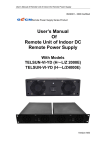
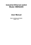
Characteristic curve of general l2t
• BT2-1600~BT2-6300
T/I (time / current) curve of type L25 intelligent controllers (OCR)
10000
Illustrational curve
The range of long-time delay
Ir1 =(0.65~1)In
t1=15s~480s
Ir1
The range of short-time delay
Ir2=(1.5~10)Ir2+OFF
t2=0.1s~0.4s
1000
t1
Instantaneous range
Ir3=(3~15)Ir1+OFF
100
long-time delay curve
t (s)
I2T ON
Ir2
10
1
t2
Short-time delay curve
0.4
0.3
I2T OFF
0.2
0.1
Instantaneous range
0.02
Instantaneous curve
0.01
0.4
1
1.5
3
Ir1
16
10
15
Air Circuit Breakers
BT2 series
Characteristic curve
• T/I (time / current) curve of type M25, M26, H26, P25 and P26 intelligent controllers (OCR)
10000
Illustrational curve
The range of long-time delay
Ir1=(0.4~I)In
t1=10s~120s
Ir1
The range of short-time delay
Ir2=(0.4~15)In+OFF
t2=0.1s~0.4s
1000
t1
Instantaneous
range
Ir3=1.6kA~35kA+OFF BT2-1600
2kA~50kA+OFF BT2-2000
2.5kA~50kA+OFF BT2-2500
4kA~65kA+OFF BT2-4000
6.3kA~80kA+OFF BT2-6300
100
long-time delay curve
t (s)
Ir2
I2T ON
10
Short-time delay curve
1
t2
0.4
0.3
I 2 T OFF
0.2
0.1
Instantaneous range
0.02
Instantaneous curve
0.01
0.4
Ir1
1
1.6
10
15
80
kA
17
Air Circuit Breakers
BT2 series
Characteristic curve
Characteristic curve of inverse time delay special It
• T/I (time / current) curve of type 25 and 26 intelligent controllers (OCR)
10000
Illustrational curve
The range of long-time delay
Ir1=(0.4~1)In
t1=10s~120s
Ir1
The range of short-time delay
Ir2=(0.4~15)In+OFF
t2=0.1s~0.4s
1000
t1
Instantaneous Ir3=1.6kA~35kA+OFF BT2-1600
2kA~50kA+OFF BT2-2000
range
2.5kA~50kA+OFF BT2-25
4kA~65kA+OFF BT2-4000
6.3kA~80kA+OFF BT2-6300
100
long-time delay curve
t (s)
I2T ON
Ir2
10
Short-time delay curve
1
t2
0.4
0.3
I2T OFF
0.2
0.1
Instantaneous range
0.02
Instantaneous curve
0.01
0.4
Ir1
18
1
1.6
10
15
kA
80
Air Circuit Breakers
BT2 series
Characteristic curve
Characteristic curve of high-voltage fuse I4t
• T/I (time / current) curve of type 25 and 26 intelligent controllers (OCR)
100000
Illustrational curve
The range of long-time delay
Ir1=(0.4~1)In
t1=60s~1440s
Ir1
10000
The range of short-time delay
Ir2=(0.4~15)In+OFF
t2=0.1s~0.4s
1000
t1
Instantaneous Ir3=1.6kA~35kA+OFF BT2-1600
range
2kA~50kA+OFF BT2-2000
2.5kA~50kA+OFF BT2-2500
4kA~65kA+OFF BT2-4000
6.3kA~80kA+OFF BT2-6300
100
long-time delay curve
t (s)
I2T ON
Ir2
10
Short-time delay curve
1
t2
0.4
0.3
0.2
I2T OFF
0.1
0.01
Instantaneous range
Instantaneous curve
0.001
0.4
Ir1
1
1.6
10
15
80
kA
19
Air Circuit Breakers
BT2 series
Characteristic curve
• T/I (time / current) curve of type M26, H26 and P26 intelligent controllers (OCR) for ground-fault protection
1000
Grounding current
Ir4=(0.4~0.8)In(BT2-1600)
Ir4=(0.2~0.8)In(BT2-2000, BT2-2500)
Ir4=(0.2~0.6)In(BT2-4000)
Ir4=(0.2~0.5)In(BT2-6300)
t4=0.1s~0.4s four steps
Ir4 Maximum 1000A (For BT2-1600)
Maximum 1200A (For BT2-2000, BT2-2500)
Maximum 1600A (For BT2-4000)
Maximum 2000A (For BT2-6300)
100
Maximum
10
t (s)
1
0.4
0.3
0.2
0.1
0.01
0.2
0.8 1
10
In
20
100
Air Circuit Breakers
BT2 series
Characteristic curve
• T/I (time / current) curve of type M25, M26, H26, P25 and P26 intelligent controllers (OCR) for load-monitoring pattern one.
10000
ILC1=(0.2~1)In
tC1=t1/2(t1=15, 30, 60, 120, 240, 480s)
ILC2=(0.2~1)In
tC2=t1/4(t1=15, 30, 60, 120, 240, 480s)
ILC2≤ILC1
ILC2
1000
ILC1
200
tC1
tC2
100
t (s)
10
1
0.1
0.2
0.8 1
10
100
In
21
Air Circuit Breakers
BT2 series
Characteristic curve
• T/I (time / current) curve of type M25, M26, H26, P25 and P26 intelligent controllers (OCR) for load-monitoring pattern two.
10000
ILC1=(0.2~1)In
tC1=t1/2(t1=15, 30, 60, 120, 240, 480s)
ILC2=(0.2~1)In
tC2=60s
ILC2
1000
ILC1
tC2
100
tC1
60
t (s)
10
1
0.1
0.2
0.4
0.8 1
10
In
22
100
communication address
3. Check whether communication
communication address is correct and
and wiring ways can't meet
distance
and wiringwithout
ways can
meet the
conflict
the requirements
requirements;
Air
Circuit
Breakers
● Errors for the setting of
The
screen
on
the
●
Extra
high
temperature
To
reduce
the ambient temperature
4.
Check
whether
the
setting
of
communication address
BT2
series
around the controller
communication address is correct and
intelligent
Accessories
without conflict
controller displays
P25、P26 Intelligent
controller
10
The screen on the “ERR9”
● Extra high temperature
around the controller
intelligent
10
controller displays13.0
“ERR9”
To reduce the ambient temperature
ACCESSORIES
Accessories
13.1 NECESSARY ACCESSORIES
13.0 ACCESSORIES
Supplied accessories
13.0
ACCESSORIES
13.0
ACCESSORIES
○ Shunt Release
Following accessories are come with each ACB's as standard
supplied.
○ Closing electro-magnet
•Shunt trip device
○ 13.1
Closing
electro-magnet
NECESSARY
ACCESSORIES
To break the ACB by remote control.
Rated voltage of control
power supply
Operating voltage (V)
Instantaneous current (A)
Breaking time (ms)
○ Shunt Release
400VAC 230VAC 220VDC 110VDC
(0.7 to 1.1) Us
0.7
1.3
No more than 30
For BT2 with frame current of 2000A and abov
For BT2-1600 Circuit Breaker
1.3
2.4
▲ Switch the breaker off by remote control
13.0 ACCESSORIES
▲ Features
For BT2-1600 Circuit Breaker
For BT2 with frame current of 2000A and abo
For BT2-1600 Circuit Breaker
For BT2 with frame current of 2000A and above
For BT2AC400
with frame current
of 2000A andDC220
above
For BT2-1600
Circuit
Breaker
13.0
ACCESSORIES
DC110
AC230
Rated Control supply voltage Us(V)
▲ After the circuit breaker is charged, the closing electro-magnet will make the energy-cha
▲▲
After
the
circuit
breaker
is
charged,
the
closing
electro-magnet
will
make
the
energy-charging
Switch
the breaker
off by remote control
13.0
ACCESSORIES
spring discharge instantly, and then switch the breaker on quickly.
•Charge Coil
Operational
Voltage(V)
(0.7~1.1)Us
spring discharge instantly,
then
switch
the breaker on quickly.
○and
Auxiliary
Switch
After the ACB's ends up its energy storage, ▲
theFeatures
closing
▲○Features
Closing electro-magnet
▲ Features
electromagnet will make the energy storing spring to release Instantaneous Current(A)
2.4
0.7
1.3
1.3
DC110
DC220
Rated
Controlelectro-magnet
supply voltage
○
Closing
DC220
RatedUs(V)
Control supplyAC400
voltage Us(V) AC230
AC400
AC230
DC110
its energy instantly, then to close the count
ACB quickly.
Rated Control supply voltage Us(V)
Rated voltage of control
power supply
Operating voltage (V)
Instantaneous current (A)
Switching-on time (ms)
AC400
Breaking Time(ms)
Operational
Voltage(V)
400VAC 230VAC 220VDC
110VDC
Operational Voltage(V)
DC220
DC110
No more than 30
(0.7~1.1)Us
(0.85~1.1)Us
(0.85~1.1)Us
2.4 1.3
1.3 0.7
1.3 1.3
·65·
1.3
1.3
2.4
AC230
Operational Voltage(V)
(0.85 to 1.1) Us
0.7
1.3
No more than 70
0.7
Instantaneous Current(A)
Instantaneous Current(A)
0.7
Instantaneous
Current(A)
1.3
2.4
2.4
For BT2-1600 Circuit Breaker
with frame current of 2000A and
Breaking Time(ms)Switching-on
No more than 30 For BT2
Time(ms)
No more than 70
Switching-on Time(ms)
No more than 70
For BT2-1600 Circuit Breaker
For BT2 with frame current of 2000A and above
▲ After the circuit breaker is charged, the closing electro-magnet will make the energy
○ Motor-driven
Operating
Mechanism
spring
discharge
instantly,
and thenBreaker
switch
the breaker
on quickly.
·65·
BT2-1600
Circuit
For
▲ After theOperating
circuit breaker
is
charged,
the closing
electro-magnet
will make
the energy-charging
○ Motor-driven
Mechanism
For BT2 with frame
▲
Features
spring discharge instantly, and then switch the breaker on quickly.
•Drive unit
ACB has the functions of drive energy storage and automatic
▲ Features
energy-restoring.
The energy storage can also be done manually.
Rated voltage of control
power supply
Operating voltage (V)
Power consumption
Energy storage time (s)
Rated Control supply voltage Us(V)
AC400
DC220
Rated Control supply voltage Us(V)
AC400
AC230
Rated
Current
Operational
Voltage(V)
400VAC 230VAC 220VDC 110VDC
(0.85 to 1.1) Us
192VA
No more than 5
Operational Voltage(V)
Instantaneous Current(A)
192W
Instantaneous Current(A)
(0.85~1.1)Us
0.7
Rated operational Voltage(V)
0.7
Switching-on Time(ms)
1.3
1.3
DC220
AC230
DC
DC110
(0.85~1.1)Us
1.3
1.3
2
Conventional thermal current Ith(A
2.4
No more than 70
230
For BT2-1600 Circuit Breaker
For13.0
BT2 withACCESSORIES
frame current of 2000A and ab
Switching-on
Time(ms)
morecurrent
than 70
For BT2-1600
Circuit Breaker
For BT2 with No
frame
of 2000A and above
13.0 ACCESSORIES
AC
○ Motor-driven Operating Mechanism
▲ The circuit breaker has the functions
energy-charging and
400of motor-driven
6 automatic energy
▲ The circuit breaker has the functions of motor-driven energy-charging
and automatic
•Auxiliary Switches
○ Auxiliary
Switch energy○ Motor-driven Operating
Mechanism
discharging.
discharging.
○ Auxiliary
Switch
▲ Energy charging
manually.
thermal
current (A) Rated capacity
Rated voltage (V) Conventional
DC can also be done220
▲ Energy charging can also be done manually.
6
▲ Features
AC
230
300VA
▲ Features
Note: For the standard type of auxiliary switch, there are four pairs of changeove
DC
400
220
110
Rated Control supply
voltage Us(V)
DC110
AC400
AC230
DC220
there
contacts
(NO)
and four pieces
of
Rated Control
supply voltage Us(V)
DC110
AC400are four pieces
AC230of normally-opened
DC220
60W
or 6 pieces of NO and 2 pieces of NC, or 2 pieces of NO and 6 pieces of NC
Operational Voltage(V)
(0.85~1.1)Us
Operational
Voltage(V)
(0.85~1.1)Us
Note: Note: For the standard type of auxiliary switch, there
are four groups
of
changeover contacts; for the special type of auxiliary switch, there are four
BT2-1600 Circuit Breaker
For
192VA
192WFor
Power Consumption
pieces of normally-opened contacts (NO) and four pieces
normally192VA Breaker
Powerof
Consumption
For BT2-1600 Circuit
For BT2 192W
with frame current of 2000A and
close contacts (NC), or 6 pieces of NO and 2 pieces of NC, or 2 pieces of
○Charging
Safety
padlock For
mechanism
at the
position
“separated”
Time(s)
No of
more
thanabove
5
For BT2-1600 Circuit Breaker
NO and 6 pieces of NC.
For BT2-1600 Circuit
Breaker
with frame
current
of 2000A
and
For circuit
BT2
with
framehas
current
ofNo2000A
and
breaker
theBT2
functions
motor-driven
energy-charging
and automatic en
Charging Time(s) ▲ The
more of
than
5above
Rated Current
discharging.
▲ The circuit breaker has the
functions of motor-driven energy-charging and automatic energy• Safety padlock mechanism at the position
of “separated”▲ Energy
Rated operational Voltage(V)
charging can also be done manually.
Conventional therm
·66·
discharging.
When the draw-out circuit
breaker
indicates
the
position
·66·
Rated Current
▲ Features
▲
Energy
charging
can
also
be
done
manually.
230
“of separated”, the locking stick can be locked with padlock
AC
▲the
Features
Rated
Control
supply
voltage Us(V) RatedAC400
after being pulled out so Rated
that operational
the rocker
of
circuit breaker
DC
AC230
DC220
capacity
Voltage(V)
Conventional
thermal
current
Ith(A)
can not be turned to the position of “test” or
“connected”.
Rated Control supply voltage Us(V)
AC400
Operational Voltage(V)
230
Padlock should be provided by users themselves.
AC
400
DC
220
Operational Voltage(V)
Power Consumption
400
6Power Consumption
Charging Time(s)
DC110
220
(0.85~1.1)Us
300VA
Note: For the standard type of auxiliary switch, there are four p
(0.85~1.1)Us
192VA
192W
there are
four pieces of normally-opened contacts (NO)
a
AC230
192VA
DC220
DC
or 6 pieces of NO and 2 pieces of NC, or 2 pieces of NO a
60W
192W
No more than 5
Safety padlock mechanism at the position of “separated”
Note: For the standard type of auxiliary switch, there are four pairs of changeover contacts; for the special type,
Charging Time(s)
No more○than
5 padlock mechanism at the position of “separ
Safety
there are four pieces of normally-opened contacts (NO) and four pieces of normally-closed contacts
(NC),
or 6 pieces of NO and 2 pieces of NC, or 2 pieces of NO and 6 pieces of NC.
·66·
·66·
○ Safety padlock mechanism at the position of “separated”
▲ When the draw-out circuit breaker is at the position
23 of “s
can be locked with padlock after being pulled out so that the rocker of
Air Circuit Breakers
BT2 series
Accessories
transformed
DC24V by the
power module to provide power supply for the intelligent controller.
13.2into
SELECTIVE
ACCESSORIES
Voltage
input to secondary terminals 1 and 2 of BT2-1600 must b
○Caution:
Special Power
Module
DC24V.▲ When the power voltage of the intelligent controller is DC24V, AC230V or AC400V,
intoisDC24V
by the
module
to provide
power in
supply
the intelligent
cont
▲transformed
The module
stuck into
thepower
standard
slideway
of 35mm
widthforinside
the switchge
Caution: Voltage input to secondary terminals 1 and 2 of BT2-1600
cabinet.
DC24V.
▲ The module is stuck into the standard slideway of 35mm in width inside the s
cabinet.
Optional accessories
• Special power module
When the power voltage of BT2-1600 circuit breaker's
intelligent control is AC230 or AC400V, it can be transformed
into DC24 by this power module for power module for power
supply of the OCR.
Note: The input of voltage to 1 and 2 terminals of the secondary circuit must be
DC24V.
This module is installed by getting stuck into the standard slideway with
35mm in width inside the switchgear cabinet.
• DC24V power module
When the power voltage of BT2-1600 circuit breaker's
○ DC Power Module
intelligent control is DC24V, it can be transformed into DC24V
by this power module for power supply of the OCR.
This module is installed by getting stuck into the standard
slideway with 35mm in width inside the switchgear cabinet.
○ DC Power Module
• DC power supply module
When power supply of the secondary circuit is DC220V,
110V, it should be transformed into DC24V by this module for
power supply of the OCR.
• Under-voltage release
The under-voltage release consists of release coil and control
unit.
The under-voltage release works in two ways: operating
instantaneously and operating in time delay.
In connection wit
○ Under-voltage release
There are four specifications of time delay for the undervoltage time delay release: 0.5s, 1s, 2s and 3s. Users should
consult with the manufacturer in the light of their order about
When power supply of the secondary circuit is DC220V, itINPUT
should be transformed into DC24
special time-delay specifications as from 3s and above up to
by this module to provide power supply for the intelligent controller.
○Electrical
9s. The time delay accurary
is ±10%.mechanism for the indication of draw-out socket's position
Under-volt age Time-delayModule
The Under-voltage release
of BT2-1600
▲ When
the mainmust
bodybeofcombined
the draw-out circuit breaker and the draw-out socket are at the
with the time-delayposition
moduleofwhich
is installed “test”
by gettingand
stuck
o
“separated”,
“connected” respectively, three electrical
mechanisms
·68·
When power supply of the secondary
circuit is DC220V, it should be transformed int
into the standard slideway with 35mm in width.The module
for the indication of draw-out socket’ s location can output the electrical signals corresponding
input terminals connect with main circuit,the output terminals
by this module to provide power supply for the intelligent controller.
OUTPUT
In connection wit
with31,
three
above respectively. These mechanisms are installed inside the draw-out socket.
connect with terminal
32 positions
of the breaker.
13.0 ACCESSORIES
13.0 ACCESSORIES
A C230V
0.5s
▲ Features
Rated operational Voltage Ue(V)
1s
2s
3s
Fuju Electric FA
31 and 32 in the
For BT2-1600 Circuit Breaker Delay Module of Under-voltage
·68·
230
delay release for BT2-1600
Choice of communicate
accessories
Conventional
Thermal Current Ith(A)
10
• Under-voltage signal
• Components of draw-out socket communication module
You can achieve
• The components of draw-out
socket communication.
Rated Operational
current Ie(A)
1.5 the information through the upper device
that the circuit breaker is tripping operation under-voltage.
module consists of the draw-out socket communication
• Fault-trip signal
module outside of the circuit breaker and the draw-out
You can achieve the information through the upper device
socket communication parts inside of the circuit breaker.
○Components of draw-out socket communication
module
that the circuit breaker is tripping operation because of over
The draw-out socket communication parts are installed
▲
The
components
of
draw-out
socket
communication
loading short circuit or earth protection of the connection
inside of the draw-out socket to provide the status signals of
.module
consists of the
draw-out
socket communication
and module
devices.
such three positions
as “separated”,
“test”and
“connected”of
BT2 with frame current of 2000A and above
the main body of outside
the draw-out
circuit
breaker
and
the
drawof the circuit breaker and the draw-out socket
out socket. The draw-out
socket parts
communication
The under-voltage release consists of release coil and control unit;
communication
inside of themodule,
circuit breaker. The ▲
draw-out
which can provide the function of reading the address of
▲
The under-voltage release operates in two ways: operate instantaneou
socket
communication
parts
are
installed
inside
of
the
draw-out
the circuit breaker and display the status indication of the
time
delay;
socket
to
provide
the
status
signals
of
such
three
positions
as
main body and three positions of the draw-out socket etc,
▲
There
“separated”,
“test”
and slideway
“connected” of the main body of are four specifications of time delay for the under-voltage time del
is installed by getting
stuck into the
standard
with 35mm in width
inside
the
switchgear
cabinet.
The
two
2s and 3s.
Users should consult with the manufacturer in the light of their order a
socket.The
drawthe draw-out circuit breaker and the
draw-out
parts of the draw-out
socket
communication
module
are
specifications
as from 3s and above up to 9s. The time delay accurary is ±1
out socket communication module, which candelay
provide
the
connected with soft conducting lines.
▲
The
delay
module
should be additionally equipped for the under-voltage
functionsignal
of reading the address of the circuit breaker and display
• Ready-for-switching-on
module
input
connects
with
the main circuit, and the output connects with the wir
indication
of the
bodydevice
and three positions of the
You can achieve the
the status
information
through
themain
uplever
and
32
in
the
secondary
circuit;
that the circuit breaker
is ready
for etc,
switching-on.
draw-out
socket
is installed by getting stuck into the
24
▲ If the voltage of power supply returns to 85% Us and above in half of
standard slideway with 35mm in width inside the switchgear
circuit
breakers will not break. The module is stuck into the standard slideway of
cabinet. The two parts of the draw-out socket communication
▲
Features
module are connected with soft conducting lines.
Air Circuit Breakers
BT2 series
Accessories
Choice of mechanical interlock accessories
• Two sets of circuit breakers put horizontally and interlocked
with steel cable or stacked and interlocked with connecting
rods
(the style of interlock between two sets of circuit breakers
with connecting rods and aperture dimensions of their
bases see the counterpart of three sets of circuit breakers)
2m (max)
Wiring diagram
Possible operation pattern
1QF
1QF
Circuit breaker 1
2QF
0
1
0
Circuit breaker 2
• Three sets of circuit breakers stacked and interlocked
with connecting rods or three sets of circuit breakers put
horizontally and interlocked with steel cable (without BT21600).
• Stacked and interlocked
2QF
0
0
1
Wiring diagram
Possible operation Pattern
Pattern one: three sets of power supply can only
close one sets of circuit breaker
Pattern two: two sets of common power supply plus
one sets of standly power supply
Pattern three: two sets of power supply plus a piece
of coupling busbar
25
Air Circuit Breakers
BT2 series
Accessories
• Steel cable interlocked
urrent transformer with neutral line N connected
C
externally
interlock between two sets of circuit breakers. The maximal
• This current transformer, which is used together with circuit
distance of two circuit breakers is 2m.
breakers with three poles in the power distribution system
ofcircuit
TN-S, installed in the neutral line N with 2m at maximum
Wiring
diagram
Possible
operation
pattern
In
connection
with
the
main
er-voltage release
far from the installation point.
Pattern three:Two sets of power supply plus a
• Characteristics
input
style of interlock of three circuit breakers see the style of
13.0 TheACCESSORIES
INPUT
piece of coupling busbar
Rated working voltage
Ue (V)
Acting voltage
(V)
Reliable switching voltage
(V)
output Reliable switching resistant voltage (V)
Power consumption
Under-volt age Time-delayModule
A C230V
0.5s
1s
2s
3s
Fuju Electric FA
AC400
AC230
(0.35~0.7) Us
(0.85~1.1) Us
≤0.35Us
12VA
Note: In the electrified metworks where thunder and rain often happens or whose
In connection with the terminals
ofsupply is not stable, under-voltage release with time delay is highly
power
31 and 32 in the secondary circuit
recommended to protect the circuit breader from releasing due to transient
voltage-lowering. Generally, delay time, which is selective by users , is 0.5s,
T2-1600 Circuit Breaker Delay Module of Under-voltage
OUTPUT
1s, 2s and 3s.
delay release for BT2-1600
BT2 with frame current of 2000A and above
BT2-2000 and above
The under-voltage release consists of release coil and control unit;
The under-voltage release operates in two ways: operate instantaneously and operate in
Electrical mechanism for the indication of draw-out
lay;
socket's position
▲ There are• four
specifications
of time
delay
for the under-voltage
time
When
the main body
of the
draw-out
circuit breaker
anddelay release: 0.5s, 1s,
3s. Users should
consult
with
the
manufacturer
in
the
light
of
their
order
about special timethe draw-out socket are at the position of “separated”, “test”
“connected”
respectively,
three
electrical
mechanisms
pecificationsand
as from
3s and above
up to 9s. The
time
delay accurary
is ±10%;
the indication
of draw-out equipped
socket's location
can output delay release. The
▲ The delay for
module
should be additionally
for the under-voltage
the electrical signals corresponding with three positions
input connects with the main circuit, and the output connects with the wiring terminals of 31
above respectively. These mechanisms are installed inside
in the secondary
circuit; socket.
the draw-out
▲ If the voltage
of
power supply returns to 85% Us and above in half of the delay time, the
• Characteristics
breakers will
notworking
break. voltage
The module is stuck into Ue
the (V)
standard
Rated
230 slideway of 35mm in width.
▲ FeaturesConvertional thermal current
Ith (A) 10
Rated working current
Rated control supply voltage Us(V)
Ie (A)
1.5
AC400
AC230
(0.35~0.7)Us
Operational Voltage(V)
lectrical module for indication of ready-for-switchingE
on
Reliable Switching-on Voltage(V)
(0.85~1.1)Us
• This electrical module indicates that the ciruit breaker is
ready for switching-on.
≤0.35Us
Reliable Switching-on Resistant Voltage(V)
• Characteristics
Rated
working
voltage
Power
Consumption
Convertional thermal current
Rated working current
Ue (V)
Ith (A)
Ie (A)
·69·
26
230
10
1.5
12VA
附
件 ACCESSORIES
“分闸”锁定装置
“分闸”锁定装置
“Break” lock mechanism
“Break” lock mechanism
“分闸”锁定装置
“Break”lock
mechanism
“Break” lock mechanism
“分闸”锁定装置
Air Circuit Breakers
“分闸”锁定装置
“分闸”锁定装置可将断路器的断开按钮锁定在
BT2 series
“分闸”锁定装置可将断路器的断开按钮锁定在
按下置上,此时,断路器将不能闭合。
Accessories
按下置上,此时,断路器将不能闭合。
用户选装后,工厂提供锁和钥匙。
用户选装后,工厂提供锁和钥匙。
一台断路器配一把锁和一把钥匙;
一台断路器配一把锁和一把钥匙;
二台断路器配二把相同的锁和一把钥匙;
二台断路器配二把相同的锁和一把钥匙;
三台断路器配三把相同的锁和二把钥匙。
“分闸”锁定装置
三台断路器配三把相同的锁和二把钥匙。
•“分闸”锁定装置可将断路器的断开按钮锁定在
“Break”lock lock
mechanism
“Break”
mechanism
•“Break”
“Break”lock
mechanism
can lock
thelock
“OFF”
of the
lock
mechanism
“
Break”
lock
mechanism
can
thebutton
“ OFF”
按下置上,此时,断路器将不能闭合。
circuit
breaker
on
the
pressed
position.
As
a
result,
the circuit
lockbreaker
mechanism
can
lock the
“ OFF”
button“
ofBreak”
the can
circuit
on the
pressed
position.
As a
breaker
not
be
switched
on.
用户选装后,工厂提供锁和钥匙。
button
of
breaker
the
pressedbyposition.
• Athe
fterthe
thiscircuit
lock
mechanism
was
users, theAs a
result,
circuit
breaker
can on
not
bechosen
switched
on.
一台断路器配一把锁和一把钥匙;
manufacturer
would
provide
lock
and
key.
result,After
the circuit
breaker
can
not
be
switched
on.
this lock mechanism was chosen by users, the
• After
O
ne set
of lock
circuitmechanism
breaker is outfitted
with one
lock and
二台断路器配二把相同的锁和一把钥匙;
this
was key.
chosen
by users,
theone
manufacturer
would
provide lock and
key.
manufacturer
provide
lock are
and
key. with
三台断路器配三把相同的锁和二把钥匙。
• One
T
wo sets
of circuit
circuit
breakers
outfitted
set would
of
breaker
is outfitted
withtwo
onesame
locklocks
and
one
key.
One
set
of
circuit
breaker
is
outfitted
with
one
lock
“Break”
lock mechanism
and one
key.
• Three
sets of circuit breakers are outfitted with three same
and one
key.
“
Break”
mechanism
the “
OFF”
Two
sets
of lock
circuit
breakers can
are lock
outfitted
with
two
locks
and two
keys.
Two
sets
of
circuit
breakers
are
outfitted
with
twoa
button
of
the
circuit
breaker
on
the
pressed
position.
As
same locks and one key.
same
locks
and
key. can
result,Three
the circuit
not be are
switched
on. with three
setsone
ofbreaker
circuit
breakers
outfitted
Three
sets
of
circuit
breakers
are
outfitted
After
this
lock
mechanism
was
chosen
by with
users,three
the
same locks and two keys.
•
“
Button”locking
device
same
locks
and
two
keys.
manufacturer would provide lock and key.
• When installed “Button”locking device, it can prevented
One
set of from
circuit
breakerbutton
is outfitted
with one
somebody
operating
of switching-on
or lock
switching
按钮锁定装置
off
by
mistake.
按钮锁定装置
and one
key.
加装按钮锁定装置可防止误操作合闸或分闸按
•Two
Padlock
be provided
by users
themselves.
setsshould
of circuit
breakers
are outfitted
with two
钮。 加装按钮锁定装置可防止误操作合闸或分闸按
钮。
same 挂锁用户自备。
locks and one key.
挂锁用户自备。
Three
sets oflocking
circuitdevice
breakers are outfitted with three
“Button”
same “Button”
locks and
two
keys.
locking
When
installed
“ device
Button” locking device, it can
When
installed
“ operating
Button” button
locking
device, it can
prevented somebody from
of switching-on
or
prevented
somebody
from
operating
button
of
switching-on
or
按钮锁定装置
switching
off by mistake.
switching
off byshould
mistake.
加装按钮锁定装置可防止误操作合闸或分闸按
Padlock
be provided by users themselves.
Padlock
should
be provided by users themselves.
钮。 计数器
• Counter
计数器
•挂锁用户自备。
The counter can count mechanical operation times
计数器累计断路器机械操作的次数,用户一目了
accumulatively,
which
makes users be clear at a glance.
“Button”
locking
device
计数器累计断路器机械操作的次数,用户一目了
然。
然。 When
Counterinstalled “ Button” locking device, it can
prevented
somebody from operating button of switching-on or
Counter
The
counter can count mechanical operation times
switching
off
by mistake.
The
counter
canmakes
countusers
mechanical
accumulatively,
which
be clear operation
at a glance.times
Padlock should
bemakes
provided
by users
themselves.
accumulatively,
which
users
be clear
at a glance.
相间隔板
计数器
•相间隔板
Separator plate between phases
相间隔板加强母排间绝缘,为断路器选择件,用
•计数器累计断路器机械操作的次数,用户一目了
Separator plates between phases which strengthen insulation
相间隔板加强母排间绝缘,为断路器选择件,用
户需要时可配置。
然。 between bus-bars are optional and will be equipped as
户需要时可配置。
needed byplate
users.
Separator
between phases
Counter
Separator
plate
between phases
Separator
plates
phases which
strengthen
The counter can between
count mechanical
operation
times
Separator
plates
between
phases
which
strengthen
insulation
between
bus-bars
are
optional
and
will
accumulatively, which makes users be clear at a glance. be
insulation
bus-bars
equipped asbetween
needed by
users. are optional and will be
equipped
as
needed
by
users.
相间隔板
相间隔板加强母排间绝缘,为断路器选择件,用
户需要时可配置。
45
45 Separator plate between phases
Separator plates between phases which strengthen
insulation between bus-bars are optional and will be
equipped as needed by users.
45
27
Air Circuit Breakers
BT2 series
Technical data
Power consumption and derating coefficient
• Power consumption (Environment temperature +40°C)
Power consumption is the overall consumption measured
under with the circuit breaker is electrified with current below
frame current.
Type
BT2-1600
BT2-2000
BT2-2500
BT2-4000
BT2-6300
Three poles/four poles (W)
Fixed type
152
203.6
356.8
648.96
1050.1
Draw-out type
408
382.8
823.4
897.6
1200.2
• Derating coefficient
The following table shows continual current-loading
capacity of circuit breakers at different ambient environment
temperature and under the conditions of the satisfaction of
conventional heating in IEC60947-2
Ambient Environment temperature
Continual current-loading
Inm=1600A
capacity
Inm=2000A
Inm=2500A
Inm=4000A
Inm=6300A
+40°C
1Inm
1Inm
1Inm
1Inm
1Inm
+45°C
0.99Inm
0.97Inm
0.96Inm
0.95Inm
0.93Inm
+50°C
0.96Inm
0.91Inm
0.90Inm
0.89Inm
0.87Inm
+55°C
0.90Inm
0.87Inm
0.86Inm
0.85Inm
0.82Inm
+60°C
0.87Inm
0.82Inm
0.80Inm
0.78Inm
0.75Inm
Derating for high-elevation
If elevation exceeds work environment 2000m, electric
property of circuit breaker can correct according to following
table:
elevation (m)
Power-frequency withstand voltage (V)
Correction factor of operational current
Correction factor of short-circuit breaking capacity
28
2000
3500
1
1
3000
3150
0.93
0.83
4000
2500
0.88
0.71
5000
2000
0.82
0.63
Air Circuit Breakers
BT2 series
Technical data
Reference table of main circuit wiring copper bar for draw-out circuit breaders
Rated frame current (A)
Rated current (A)
1600
200
400
630
800
1000
1250
1600
630
800
1000
1250
1600
2000
1250
1600
2000
2500
2000
2500
2900
3200
3600
4000
4000
5000
6300
2000
2500
4000
6300
Specifications of copper bars
Number
1
1
2
2
3
4
2
2
2
2
3
2
3
3
2
3
4
3
4
3
4
4
5
5
6
8
Size (mm×mm)
20×5
50×5
40×5
50×5
40×5
40×5
50×10
50×5
60×5
60×5
60×5
60×10
60×10
60×5
60×10
60×10
60×10
100×5
100×5
100×10
100×10
100×10
100×10
100×10
100×10
100×10
The specifications of copper bars in the above table are introduced under which the circuit breakers by open installation are at maximum ambient environment
temperature of 40°C and satisfy conventional heating in IEC60947-2.
29
Air Circuit Breakers
BT2 series
Dimensions and mounting
Dimensions and mounting, mm
BT2-1600 Air Circuit Breaker with three poles (draw-out type)
Current specifications
800A, 1000A, 1250A, 1600A
200A, 400A, 630A
Direction A
L (mm)
15
10
Outside of the
cabinet doo
Base point
“Separated”position
Horizontal (back set)
Direction D
Outside of the
cabinet door
Base point
“Separated”position
Vertical (back set)
Direction C
30
Air Circuit Breakers
BT2 series
Dimensions and mounting
Dimensions and mounting, mm
BT2-1600 Air Circuit Breaker with four poles (draw-out type)
Current specifications
800A, 1000A, 1250A, 1600A
200A, 400A, 630A
Direction A
L (mm)
15
10
70
25
70
70
16-ø11
50
N pole
Outside of the
cabinet door
51
A
Base point
72.5
46
77.5
102.5
102
D
57
297
201
60
“Separated”position
Horizontal (back set)
C
Direction D
2-ø6.5
Outside of the
cabinet door
51
15
16-ø11
2-6.5x8.5
Base point
72.5
46
102.5
77.5
297
“Separated”position
Vertical (back set)
Direction C
70
70
70
L
N pole
31
Air Circuit Breakers
BT2 series
Dimensions and mounting
Dimensions and mounting, mm
BT2-1600 Air Circuit Breaker with three poles (fixed type)
Current specifications
800A, 1000A, 1250A, 1600A
200A, 400A, 630A
Direction A
L (mm)
15
10
50
25
12-ø11
70
Outside of the
cabinet door
70
A
32
4-ø6.5
Base
point
4-ø6.5
100
192
197
10
38.5 50.6
234
10
Horizontal (back set)
244
Outside of the
cabinet door
C
32
4-ø6.5
15
Base
point
214
Breaker
base
4-ø6.5
100
192
197
234
Aperture dimensions of the back plate
at the time of hanging type installation
Vertical (back set)
Direction C
L
70
32
38.5 50.6
70
Air Circuit Breakers
BT2 series
Dimensions and mounting
Dimensions and mounting, mm
BT2-1600 Air Circuit Breaker with four poles (fixed type)
Current specifications
800A, 1000A, 1250A, 1600A
200A, 400A, 630A
Direction A
L (mm)
15
10
25
50
16-ø11
70
70
70
N pole
Outside of the
cabinet door
A
32
4-ø6.5
Base
point
100
192
197
4-ø6.5
38.5 50.6
10
304
10
Horizontal (back set)
314
Outside of the
cabinet door
C
32
4-ø6.5
15
Base
point
284
Breaker
base
4-ø6.5
100
192
197
304
Aperture dimensions of the back plate
at the time of hanging type installation
38.5 50.6
Vertical (back set)
Direction C
L
70
70
70
N pole
33
Air Circuit Breakers
BT2 series
Dimensions and mounting
Dimensions and mounting, mm
BT2-2000 Air Circuit Breaker with three poles (draw-out type)
Direction A
Current specifications
2000A
630A, 800A, 1000A,
1250A, 1600A
L (mm)
20
15
H (mm)
20
15
A (mm)
30
25
95
30
Outside of the
cabinet door
61
95
24-ø11
70
A
Base
point
10
47
97
102
175
41
D
265
41
390
“Separated”position
Horizontal (back set)
C
Outside of the
cabinet door
Direction D
60
15
15
2-ø14
11x17
Base
point
24-ø11
ø11
10
47
97
102
175
66
390
“Separated”position
Vertical (back set)
Direction C
95
60
34
95
10
30
Air Circuit Breakers
BT2 series
Dimensions and mounting
Dimensions and mounting, mm
BT2-2000 Air Circuit Breaker with four poles (draw-out type)
Direction A
Current specifications
2000A
630A, 800A, 1000A,
1250A, 1600A
L (mm)
20
15
H (mm)
20
15
A (mm)
30
25
95
95
95
N pole 30
Outside of the
cabinet door
61
32-ø11
70
A
Base
point
10
47
97
102
175
41
D
360
41
390
“Separated”position
Horizontal (back set)
C
Direction D
Outside of the
cabinet door
60
30
2-ø14
11x17
Base
point
ø11
10
47
97
102
15
32-ø11
175
66
390
“Separated”position
Vertical (back set)
Direction C
95
N pole
95
60
95
10
30
35
Air Circuit Breakers
BT2 series
Dimensions and mounting
Dimensions and mounting, mm
BT2-2000 Air Circuit Breaker with three poles (fixed type)
Direction A
Current specifications
2000A
630A, 800A, 1000A,
1250A, 1600A
L (mm)
20
15
A (mm)
269
264
W (mm)
20
15
B (mm)
13
3
95
30
Outside of the
cabinet door
95
24-ø11
60
A
61
4-ø12
Base
point
150
69.5
11
340
Base
point
11
285
290
Horizontal (back set)
Outside of the
cabinet door
C
60
Direction C
95
60
95
10
30
24-ø11
Base
point
150
285
Vertical (back set)
36
15
69.5
30
94
Air Circuit Breakers
BT2 series
Dimensions and mounting
Dimensions and mounting, mm
BT2-2000 Air Circuit Breaker with four poles (fixed type)
Current specifications
2000A
630A, 800A, 1000A,
1250A, 1600A
L (mm)
20
15
A (mm)
269
264
W (mm)
20
15
B (mm)
13
3
Direction A
95
95
N pole 30
Outside of the
cabinet door
95
32-ø11
60
A
61
Base
point
4-ø12
150
285
69.5
11
435
Base
point
11
290
Horizontal (back set)
Outside of the
cabinet door
C
Direction C
95
N pole
95
60
60
95
10
30
32-ø11
Base
point
150
285
15
69.5
30
94
Horizontal (back set)
37
Air Circuit Breakers
BT2 series
Dimensions and mounting
Dimensions and mounting, mm
BT2-2500 Air Circuit Breaker with three poles (draw-out type)
Current specifications
2000A, 2500A
1250A, 1600A
Direction A
L (mm)
20
15
95
30
Outside of the
cabinet door
62
95
24-ø11
70
A
Base
point
10
47
97
102
175
41
D
265
41
390
“Separated”position
Horizontal (back set)
C
Direction D
Outside of the
cabinet door
62
2-ø14
24-ø11
11x17
Base
point
ø11
10
47
97
102
175
390
“Separated”position
Vertical (back set)
Direction C
95
L
38
95
Air Circuit Breakers
BT2 series
Dimensions and mounting
Dimensions and mounting, mm
BT2-2500 Air Circuit Breaker with four poles (draw-out type)
Current specifications
2000A, 2500A
1250A, 1600A
Direction A
L (mm)
20
15
95
30
95
95
32-ø11
70
N pole
Outside of the
cabinet door
62
A
Base
point
10
47
175
97
102
41
D
360
41
390
“Separated”position
Horizontal (back set)
C
Outside of the
cabinet door
62
Direction D
32-ø11
2-ø14
Base
point
11x17
10
ø11
47
97
102
175
390
“Separated”position
Vertical (back set)
Direction C
95
95
95
L
N pole
39
Air Circuit Breakers
BT2 series
Dimensions and mounting
Dimensions and mounting, mm
BT2-2500 Air Circuit Breaker with three poles (fixed type)
Current specifications
2000A, 2500A
1250A, 1600A
L (mm)
20
15
95
95
Direction A
C (mm)
132
134.5
95
30
24-ø11
95
24-ø11
60
30
60
A
Outside of the
cabinet door
A
61
61
4-ø12
Base
point
150
4-ø12
69.5
285
150
290
285
290
11
69.5
340
11
11
Base
point
340
11
Horizontal (back set)
BT2-2500 Air Circuit Breaker with four poles (fixed type)
Current specifications
2000A, 2500A
1250A, 1600A
L (mm)
20
15
C (mm)
132
134.5
95
95
N pole
Direction A
95
95
95
30
32-ø11
32-ø11
60
30
Outside of the
cabinet door
95
60
A
A
61
61
Base
point
4-ø12
4-ø12
150
69.5
285
150
69.5
290
285
Horizontal 290
(back set)
40
11
11
435
435
Base
point
11
11
Air Circuit Breakers
BT2 series
Dimensions and mounting
Dimensions and mounting, mm
BT2-4000 Air Circuit Breaker with three poles (draw-out type)
Direction A
130
50
Outside of the
cabinet door
130
24-ø17
100
A
104
Base
point
10
97
47
175
102
37
B
37
327
395
“Separated”position
Horizontal (back set)
C
Direction B
Outside of the
cabinet door
ø11
11x17
104
50
2-ø14
25
24-ø17
Base
point
Base
point
10
47
97
102
175
395
“Separated”position
Horizontal (back set)
Direction C
113
113
10
30
41
Air Circuit Breakers
BT2 series
Dimensions and mounting
Dimensions and mounting, mm
BT2-4000 Air Circuit Breaker with four poles (draw-out type)
Direction A
130
130
N pole 50
Outside of the
cabinet door
130
32-ø17
100
A
104
Base
point
10
97
175
102
47
37
B
440
37
395
“Separated”position
Horizontal (back set)
C
Direction B
Outside of the
cabinet door
ø11
11x17
104
50
2-ø14
32-ø17
Base
point
Base
point
10
47
97
175
102
395
“Separated”position
Vertical (back set)
Direction C
113
N pole
42
113
10
30
113
25
Air Circuit Breakers
BT2 series
Dimensions and mounting
Dimensions and mounting, mm
BT2-4000 Air Circuit Breaker with three poles (fixed type)
Direction A
113
40
Outside of the
cabinet door
113
24-ø13
80
A
82
Base
point
4-ø12
150
69.5
11
Base
point
392
11
285
290
Horizontal (back set)
BT2-4000 Air Circuit Breaker with four poles (fixed type)
Direction A
113
113
N pole 40
Outside of the
cabinet door
113
32-ø13
80
A
82
Base
point
4-ø12
150
285
290
69.5
11
505
Base
point
11
Horizontal (back set)
43
Air Circuit Breakers
BT2 series
Dimensions and mounting
Dimensions and mounting, mm
BT2-6300 Air Circuit Breaker with three poles (draw-out type)
Direction A
113
50
126.5
130
113
48-ø17
100
A
Outside of the
cabinet door
126.5
183
104
Base
point
Base
point
6-ø11
10
47
77
82
258
693
395
767
“Separated”position
Horizontal (back set)
Current specifications:
In=4000A, 5000A
C
Outside of the
cabinet door
104
50
Direction C
113
126.5
113
126.5
48-ø17
113
Base
point
10
30
10
47
77
82
258
395
“Separated”position
Vertically (back set)
Current specifications:
In=4000A, 5000A, 6300A
44
6-ø11
25
Air Circuit Breakers
BT2 series
Dimensions and mounting
Dimensions and mounting, mm
BT2-6300 Air Circuit Breaker with four poles (draw-out type)
Direction A
113
130
N pole 50
113
123
113
113
64-ø17
100
A
Outside of the
cabinet door
130
239.5
104
Base
point
Base
point
6-ø11
10
47
77
82
258
95
919
993
395
“Separated”position
Horizontal (back set)
Current specifications:
In=4000A, 5000A
C
Outside of the
cabinet door
104
50
25
Direction C
113
113
113
140
113
113
113
Base
point
10
30
N pole
64-ø17
8-ø11
10
47
77
82
258
395
“Separated”position
Vertical (back set)
Current specifications:
In=4000A, 5000A, 6300A
45
Air Circuit Breakers
BT2 series
Dimensions and mounting
Dimensions and mounting, mm
BT2-6300 Air Circuit Breaker with three poles (fixed type)
Direction A
205
55 50
50 205
50 55 50
239.5
239.5
Outside of the
cabinet door
239.5
239.5
A
A
134
134
Base
point
150
150
285
285
290
290
4-ø12
4-ø12
69.5
69.5
11
11
760
760
Base
point
11
11
Horizontal (back set)
BT2-6300 Air Circuit Breaker with four poles (fixed type)
Direction A
205
55 50
50 205
50 55 50
N pole
Outside of the
cabinet door
226
226
253
253
226
226
A
A
134
134
Base
point
4-ø12
4-ø12
150
150
285
285
290
290
Horizontal (back set)
46
69.5
69.5
11
11
986
986
Base
point
11
11
Air Circuit Breakers
BT2 series
Dimensions and mounting
Door frame dimensions, mm
BT2-1600 door frame
BT2-1600 Air Circuit Breakers with three poles (draw-out)
The drawing of aperture dimensions for mounting cover of
door frame
Distance from the panel center of the circuit breaker to the
right hinge of cabinet door should be at least 227mm
10-ø6
10-ø6
216
254
Breaker
base
286
324
Breaker
base
BT2-1600 Air Circuit Breakers with three poles (fixed type)
The drawing of aperture dimensions for mounting cover of
door frame
Distance from the panel center of the circuit breaker to the
right hinge of cabinet door should be at least 227mm
Breaker
base
BT2-1600 Air Circuit Breakers with four poles (draw-out)
The drawing of aperture dimensions for mounting front cover
of door frame
Distance from the panel center of the Circuit Breaker to the
right hinge of cabinet door should be at least 262mm
216
254
10-ø6
BT2-1600 Air Circuit Breakers with four poles (fixed type)
The drawing of aperture dimensions for mounting front cover
of door frame
Distance from the panel center of the Circuit Breaker to the
right hinge of cabinet door should be at least 262mm
10-ø6
286
324
Breaker
base
47
Air Circuit Breakers
BT2 series
Dimensions and mounting
Door frame dimensions, mm
Aperture Dimension of BT2-2000 door frame
BT2-2000 Air Circuit Breakers with three poles (draw-out)
The drawing of Aperture Dimensions for mounting front cover
of cabubet door
Distance from the panel center of the circuit breaker to the
right hinge of cabinet door should be at least 256mm
Breaker base
14-ø6
Breaker base
11-ø6
175
258
312
BT2-2000 Air Circuit Breakers with four poles (draw-out)
The drawing of Aperture Dimensions for mounting front cover
of cabinut door
Distance from the panel center of the circuit breaker to the
right hinge of cabinet door should be at least 303.5mm
353
407
445
175
BT2-2000 Air Circuit Breakers with three poles (fixed)
The drawing of Aperture Dimensions for mounting front cover
of cabunet door
Distance from the panel center of the circuit breaker to the
right hinge of cabinet door should be at least 256mm
100
BT2-2000 Air Circuit Breakers with four poles (fixed)
The drawing of Aperture Dimensions for mounting front cover
of cabinut door
Distance from the panel center of the circuit breaker to the
right hinge of cabinet door should be at least 303.5mm
Breaker base
Breaker base
8-ø6
48
312
175
175
10-ø6
100
407
445
Air Circuit Breakers
BT2 series
Dimensions and mounting
Door frame dimensions, mm
Aperture Dimension of BT2-2500 door frame
BT2-2500 Air Circuit Breakers with three poles (draw-out)
The drawing of Aperture Dimensions for mounting cover of
door frame
Distance from the panel center of the circuit breaker to the
right hinge of cabinet door should be at least 256mm
BT2-2500 Air Circuit Breakers with four poles (draw-out)
The drawing of Aperture Dimensions for mounting cover of
door frame
Distance from the panel center of the circuit breaker to the
right hinge of cabinet door should be at least 303.5mm
Breaker base
Breaker base
11-ø6
175
258
312
14-ø6
353
407
445
175
BT2-2500 Air Circuit Breakers with three poles (fixed)
The drawing of Aperture Dimensions for mounting cover of
door frame
Distance from the panel center of the circuit breaker to the
right hinge of cabinet door should be at least 256mm
100
BT2-2500 Air Circuit Breakers with four poles (fixed)
The drawing of Aperture Dimensions for mounting cover of
door frame
Distance from the panel center of the circuit breaker to the
right hinge of cabinet door should be at least 303.5mm
Breaker base
Breaker base
8-ø6
312
175
175
10-ø6
100
407
445
49
Air Circuit Breakers
BT2 series
Dimensions and mounting
Door frame dimensions, mm
Aperture Dimension of BT2-4000 door frame
BT2-4000 Air Circuit Breakers with three poles (draw-out)
The drawing of Aperture Dimensions for mounting cover of
door frame
Distance from the panel center of the circuit breaker to the
right hinge of cabinet door should be at least 264mm
Breaker base
BT2-4000 Air Circuit Breakers with four poles (draw-out)
The drawing of Aperture Dimensions for mounting cover of
door frame
Distance from the panel center of the circuit breaker to the
right hinge of cabinet door should be at least 320.5mm
Breaker base
11-ø6
14-ø6
312
328
366
BT2-4000 Air Circuit Breakers with three poles (fixed)
The drawing of Aperture Dimensions for mounting cover of
door frame
Distance from the panel center of the circuit breaker to the
right hinge of cabinet door should be at least 264mm
100
425
441
479
BT2-4000 Air Circuit Breakers with four poles (fixed)
The drawing of Aperture Dimensions for mounting cover of
door frame
Distance from the panel center of the circuit breaker to the
right hinge of cabinet door should be at least 320.5mm
Breaker base
Breaker base
10-ø6
8-ø6
328
366
50
100
441
479
Air Circuit Breakers
BT2 series
Dimensions and mounting
Door frame dimensions, mm
Aperture Dimension of BT2-6300 door frame
BT2-6300 Air Circuit Breakers with three poles (draw-out)
The drawing of Aperture Dimensions for mounting cover of
door frame
Distance from the panel center of the circuit breaker to the
right hinge of cabinet door should be at least 264mm
Breaker base
11-ø6
312
328
366
BT2-6300 Air Circuit Breakers with three poles (fixed)
The drawing of Aperture Dimensions for mounting cover of
door frame
Distance from the panel center of the circuit breaker to the
right hinge of cabinet door should be at least 264mm
BT2-6300 Air Circuit Breakers with four poles (draw-out)
The drawing of Aperture Dimensions for mounting cover of
door frame
Distance from the panel center of the circuit breaker to the
right hinge of cabinet door should be at least 320.5mm
Breaker 14-ø6
base
100
425
441
479
BT2-6300 Air Circuit Breakers with four poles (fixed)
The drawing of Aperture Dimensions for mounting cover of
door frame
Distance from the panel center of the circuit breaker to the
right hinge of cabinet door should be at least 320.5mm
Breaker base
Breaker base
10-ø6
8-ø6
328
366
100
441
479
51
Air Circuit Breakers
BT2 series
Dimensions and mounting
Mounting safety clearance
Draw-out breaker
d2
d2
d2
d2
Minimum distance between breaker with switchboard wall or
live part.
d1 (note) (mm)
d2 (mm)
Switchboard wall
0
0
Live part
60
60
Fixed breaker
d2
d2
Minimum distance between breaker with switchboard wall or
live part.
d1 (note) (mm)
d2 (mm)
Switchboard wall
0
0
Live part
60
60
Note:secondary circuit wiring must be considered for safety clearance.
52
d2
d2
Air Circuit Breakers
BT2 series
Dimensions and mounting
自动电源转换系统外形尺寸及安装尺寸
自动电源转换系统外形尺寸及安装尺寸
OUTLINE DIMENSIONS AND MOUNTING DIMENSIONS
OF AUTOMATIC
POWERAND
SUPPLY
SWITCH
SYSTEM
OUTLINE
DIMENSIONS
MOUNTING
DIMENSIONS
OF AUTOMATIC POWER SUPPLY SWITCH SYSTEM
Dimensions
and mounting of Automatic transfer switch (ATS), mm
转接器
The switching
unit
转接器
The
switching
unit
The switching unit
Φ6.5
Φ6.5
Φ6.5
Norm al powe r s uppl y
Norm al powe r s uppl y
Norma l power s uppl y
Norma l power s uppl y
Under- voltage vol tage
Under- voltage vol tage
Norm al powe r s uppl y
Norma l power s uppl y
Under- voltage vol tage
Standin g power supply
Standin g power supply
Sta nding p ower su pply
Sta nding p ower su pply
Under- voltage vol tage
Under- voltage vol tage
Standin g power supply
Sta nding p ower su pply
Under- voltage vol tage
Switching unit
unit
Switching
Switching unit
136
146
136
66.5
66.5
146
R、S型自动转换控制器
Type RR、S型自动转换控制器
and S Automatic transfer controller
R、S型自动转换控制器
Type R and S Automatic transfer controller
Type R and S Automatic transfer controller
R
R
Autom atic
atic power
power supply
supply switch
switch syste
syste m
m of
of typ
typ ee R
R
Autom
R
Autom atic power
U R supply switch syste m of typ e R
U NN
U
UN
UR
UR
N ormal s upply
N ormal s upply
N ormal s upply
C lose
C lose
Stand by Pow er
Stand by Pow er
=0.5s
tt 22=0.5s
Stand by Pow er
Close
Clo se
t 2=0.5s
C lose
O pen
O pen
Clo se
Open
Open
O pen
Open
Malfu nction
Malfu nction
M alfuncti on
M alfuncti on
Auto matic
Auto matic
Norm al supp ly
Norm al supp ly
Malfu nction
M alfuncti on
Power genera ting
Power genera ting
Norm al supp ly
8 16
44 8 16
24
22
24
32
11 4 8 16 32
0.5
64
0.5
64
2
24
1
32
33
0.5
64
Sta nding
Sta nding
tt ss
Sta nding
UNN =I
=I t 3 s
U
8 16
44 8 16
24
22
24
32
11 4 8 16 32
0.5
64
0.52
64
24
1
1
1
32
0.5
64
tt ss
t 1s
Auto matic
UN =I
Norm al
Norm al
Norm al
=0.5s
tt 44 =0.5s
t 4 =0.5s
Stop
Power generaStop
ting
Stop
Former C
C hangsh
hangsh uu Switchgear
Switchgear Plant)
Plant)
Ch angshu
angshu Sw
Sw itchgear
itchgear Mfg.
Mfg. Co
Co .,., Ltd.
Ltd. (
( Former
Ch
Ch angshu Sw itchgear Mfg. Co ., Ltd. ( Former C hangsh u Switchgear Plant)
143
143
90
90
96
96
F型自动转换控制器
F型自动转换控制器
Type
F automatic
transfer controller
Type F automatic
transfer
controller
136
136
Type F automatic transfer controller
Automatic power
power su
su pplyswitch
pplyswitch system
system of
of type
type F
F
Automatic
R
R
Automatic power su pplyswitch4 system
8 16 of type F
U NN R
U
UN
U RR
U
No rmal sup ply
No rmal sup ply
UR
P ower ge ne ra tion
P ower ge ne ra tion
No rmal sup ply
Clo se
Clo se
P ower ge ne ra tion
C lose
C lose
Clo
se
Op en
Op en
C lose
O pen
O pen
Op en
O pen
Ma lfunction
Ma lfunction
M alfunctio n
M alfunctio n
N ormal supply
N ormal supply
4
4
2
2
1
1
0.5
0.5 4
2
1
0.5
Autom
a tic
Ma
lfunction
Autom
a tic
M alfunctio n
P ower ge n era ting
P ower ge n era ting
N ormal supply
4
2
2
1
1
0.5
0.5 4
2
1
0.5
8 16
24
24
32
32
8 16 64
64
2
24
2
32
tt ss
4
1
32
32
4
64
4
64
2
120
2
120
16 32240
0. 5
0. 5 8
240
4
3
64
3
120
2
0. 5
240
N
3
N
tt ss
tt ss
64
U =
=0
0t s
U
U NN=1
=1
t 1 sU
t5 s
120
180
tt ss
16
U N=88I 16
U =0
24
24
32
32
8 16 64
64
1
24
1
32
tt 5 ss
240
30 0
18 0 240 30
0
18 0
120
360
120
360
64
480
64
480
240
32
600
3218 0
30 600
0
120
6
360
6
64
480
32
600
N
N
6
U =
= II t s
U
8 16
8 16
N
U =1
Stop
UN =I
64
t 2 sU
UNN =0
=0
16 32 64N
16 32 64
8
96
8
96
4
120
4
120
1
180
1 16 32 64180
8
96
5
Autom a tic
Stop
Stop
P ower ge n era ting
UNN =I
=I
U
U NN =0
=0
U
U N =0
U N=440 88
2
2
1
1
0. 5
0. 5 4
2
1
0. 5
t4 s
Changshu SS witchg
witchg ear
ear Plant)
Plant)
Changshu Sw
Sw itchge
itchge ar
ar Mfg.
Mfg. Co.,
Co., Ltd.
Ltd. (Former
(Former Changshu
Changshu
Changshu Sw itchge ar Mfg. Co., Ltd. (Former Changshu S witchg ear Plant)
143
143
16
16
24
24
32
32
8 16 64
64
24
32
64
tt 44 ss
90
90
96
96
75
75
136
136
53
54
Over-current release
Power-driven
switching-off
Power-driven
switting-on
Auxiliary switch
Location
indication
Tes t
ind ication
Connec tion
indication
Spaciel Note: When the voltage of auxiliary power supply is AC230V or AC400V, power supply module of BT2-1600 intelligent should be transformed into DC24V in connection with terminals of 1 and 2.
When the voltage of power supply is DC110V or DC220V, DC power supply module should be transformed into DC24V in connection with terminals of 1 and 2.
When the voltage of auxiliary power supply is DC24V, DC24V power supply module should be transformed into DC24V in connection with termimnals 1 and 2.
Main circuit
Wiring diagram of the secondary circuit of BT2-1600 circuit breakers
equipped with type L25, M25, M26, P25 and P26 intelligent controllers (OCR)
Air Circuit Breakers
BT2 series
Wiring diagram
断路器二次回路接线图 WIRING DIAGRAM OF SECONDARY CIRCUIT
Wiring diagram of secondary circuit
76
Processing
unit
Over-current release
Power-driven
switching-off
Power-driven
switching-on
Auxiliary switch
Co nnec tion
indicati on
Te st
in dicat ion
Location current
indication
Separtion
indication
Separtion
indicatio n
Output signal module
Output signal of location
indication
Special Note: When the voltage of auxiliary power supply is AC230V or AC400V, power supply module of BT2-1600 intelligent should be transformed into DC24V in connection with terminals of 1 and 2.
When the voltage of power supply is DC110V or DC220V, DC power supply module should be transformed into DC24V in connection with terminals of 1 and 2.
When the voltage of auxiliary power supply is DC24V, DC24V power supply module should be transformed into DC24V in connection with terminals of 1 and 2.
Main circuit
Wiring diagram of the secondary circuit of BT2-1600 circuit breakers equipped with type H26, P25 and P26 communicate intelligent controllers (OCR)
Air Circuit Breakers
BT2 series
Wiring diagram
断路器二次回路接线图 WIRING DIAGRAM OF SECONDARY CIRCUIT
77
55
Main
circuit
Processing
unit
Over-current release
Power-driven
switching-off
Power-driven
switching-on
Auxiliary switch
Test
Connection
Test
indication
Location
indication
Sepatation
56
Connection
indication
Wiring diagram of the secondary circuit of BT2-2000~6300 circuit breakers equipped with type L25, M25, M26, P26 intelligent controllers (OCR)
Air Circuit Breakers
BT2 series
Wiring diagram
断路器二次回路接线图 WIRING DIAGRAM OF SECONDARY CIRCUIT
78
Main
circuit
Processing
unit
Power-driven
switching-off
Power-driven
switching-on
Auxiliary switch
Te st
indication
Connection
indication
Location current
indication
Se partion
indication
Separtion
indication
Over-current release
Out put signal of location
indication
Wiring diagram of the secondary circuit of BT2-2000~6300 circuit breakers equipped with type H26, P25, and P26 communicate intelligent controllers (OCR)
Air Circuit Breakers
BT2 series
Wiring diagram
断路器二次回路接线图 WIRING DIAGRAM OF SECONDARY CIRCUIT
79
57
Wiring diagram of the automatic transfer switch (ATS) for normal supply to standby supply system
BT2-1600 circuit breakers and the auxiliary switch has four pairs of change-over contacts
Air Circuit Breakers
BT2 series
Wiring diagram
自动电源转换系统电气线路图
1 2 3 4 5 6 7 8 9
10111213141516171819
58
80
Wiring diagram of the automatic transfer switch (ATS) for nomal supply to power generating supply system
BT2-1600 circuit breakers and the auxiliary switch has four pairs of contacts
Air Circuit Breakers
BT2 series
Wiring diagram
自动电源转换系统电气线路图
1 2 3 4 5 6 7 8 9
10111213141516171819
81
59
Wiring diagram of the automatic transfer switch (ATS) for normal supply to standby supply system
BT2-2000~6300 circuit breakers and the auxiliary switch has four pairs of changeover contacts
Air Circuit Breakers
BT2 series
Wiring diagram
自动电源转换系统电气线路图
1 2 3 4 5 6 7 8 9
1011121314151617 1819
82
60
Wiring diagram of the automatic transfer switch (ATS) for normal supply to power generating
supply system
BT2-2000~6300 circuit breakers and the auxiliary switch has four pairs of contacts
Air Circuit Breakers
BT2 series
Wiring diagram
自动电源转换系统电气线路图
1 2 3 4 5 6 7 8 9
1011121314 1516 1718 19
83
61
Air Circuit Breakers
BT2 series
Ordering form
Ordering form
1. Users should make sure of their detailed acquaintance of
2. The company would configure by“Factory's setting values
the products’ technological materials and make order by the
of the intelligent release” if users had no requirements of
“ordering form”in terms of future applicable situations of the
protection parameters when making order.
Ordering form
circuit breakers.
Ordering form
or mark √ in
(Please fill numbers in
Customer
name
Type
Use
Order quantity
BT2-
/
Standard
Connection Fixed
Humid tropical (TH)
Type L25
Basic function
Vertical (Rear connection)
Type M25
Type M26
Type H26
Type P26
Type P25
LED current
Current
indication and
LED current indication
communication LCD current indication and wattmeter function
indication
function
Long-time delay overload protection
Short-time delay short circuit protection
Instantaneous short circuit protection
Ir1
t1
Ir2
t2
Ground-fault protection
Intelligent controller (OCR)
A
Vertical (Rear connection)
Horizontal (Rear connection)
Type selection
AC690V
In=
Rated current
Horizontal (Rear connection)
Draw-out
AC400V
Rated voltage
E
)
Date
Ir3
Ir4
t4
Long-time delay overload protection
General inverse time delay (I2t)
Long-time delay overload protection
50%In
100%In
(Select setting current of N line)
OFF
50%In
100%In
200%In
(200% In for three-pole breaker + neutral line transformer BT2-6300 except)
Test function
MCR function
General inverse time delay (I2t)
Special inverse time delay (It)
High-voltage fuse type (I4t)
Thermo-analogue function
Contact wearing indication
Selective function
Fault memory
Alarm and fault indication
Self-diagnosis
Indication of voltage
Load-monitoring function:
ZSI function
Pattern one
Pattern two
Communication function
Harmonic meter
Current-imbalace display
Standard accessories
Voltage of the
intelligent controller
AC400V
DC24V
Need be selectively
equipped with DC24V
power supply module
AC230V
AC400V
Need be selectively equipped
power supply module
AC230V
AC400V
DC110V
DC220V
Closing coil
AC230V
AC400V
DC110V
DC220V
AC400V
DC110V
DC220V
Power-driven
AC230V
operation mechanism
Auxiliary switch
Standard pattern
DC220V
DC110V
Need to use with DC power supply
module
4 changeover contacts
Special pattern
4NO + 4NC
6NO + 2NC
2NO + 6NC
Lock in “OFF”
mechanism
Mechanical
interlock
AC230V
AC400V
Under-voltage instantaneous release
0.5s
Under-voltage time delay release
Two sets of circuit breakers
Two locks and one key
Three sets of circuit breakers
Three locks and two keys
Two sets of circuit breakers
Cable type interlock
1s
Cable type interlock
Pattern one of Rod type interlock
Pattern three of Rod type interlock
Draw out position indication
Interphase barrier
Ready to close indication
Push button locking device
Counter
Components of draw-out socket communication module
Signal of ready-for-switching on
Signal of under-voltage
Automatic transfer switch (ATS)
DC220V
3s
Rod type interlock
Pattern two of Rod type interlock
Connection of external CT for neutral
Communication
accessories
2s
One lock and one key
One set of circuit breaker
DC power supply module
62
AC230V
Shunt release
Under-voltage
release
Choice of accessories
BT2-2000 and above
BT2-1600
DC110V
Automatic transfer switch (ATS)
Signal of fault release
DC24V power supply module
R type
S type
F type
Air Circuit Breakers
BT2 series
Ordering notice
Ordering notice
Factory's setting values of intelligent controller
Overload long-time delay
Setting values of
current
Ir1
In
Setting values of
delay time
t1
480s
Overload long-time
I2 t
delay of P25 and P26
Short circuit short-time delay Setting values of
6Ir1
current
Ir2
Setting values of
delay time
0.2s
t2
Setting values of short circuit instantaneous current 15In (for In ≤ 1000A)
Ir3 12In (for In = 1250A, 1600A)
10In (for In ≥ 2000A)
Ground-fault
Setting values of
BT2-1600
BT2-2000
(Not for L25, M25, P25)
current
Ir4
BT2-2500
0.8In or 1000A
0.8In or 1200A
To select the
To select the
minimum
minimum
Setting values of
0.4s
delay time
t4
Load-monitoring
(Not for type L25, optional
for type M25, M26, H26,
P25 and P26)
Monitoring current
ILC1
In
Monitoring current
ILC2
In
BT2-4000
BT2-6300
0.8In or 1600A
To select the
minimum
2000A
63
Catalog Disclaimer
The information contained in this catalog does not constitute an express or implied warranty of quality, any warranty of
merchantability of fitness for a particular purpose is hereby disclaimed.
Since the user's product information, specific use application, and conditions of use are all outside of Fuji Electric FA
Components & Systems'control, it shall be the responsibility of the user to determine the suitability of any of the
products mentioned for the user's application.
One Year Limited Warranty
The products identified in this catalog shall be sold pursuant to the terms and conditions identified in the
"Conditions of Sale" issued by Fuji Electric FA with each order confirmation.
Except to the extent otherwise provided for in the Conditions of Sale issued by Fuji Electric FA, Fuji Electric FA
warrants that the Fuji Electric FA products identified in this catalog shall be free from significant defects in materials
and workmanship provided the product has not been: 1) repaired or altered by others than Fuji Electric FA; 2) subjected
to negligence, accident, misuse, or damage by circumstances beyond Fuji Electric FA's control; 3) improperly operated,
maintained or stored; or 4) used in other than normal use or service. This warranty shall apply only to defects appearing
within one (1) year from the date of shipment by Fuji Electric FA, and in such case, only if such defects are reported
to Fuji Electric FA within thirty (30) days of discovery by purchaser. Such notice should be submitted in writing to Fuji
Electric FA at 5-7, Nihonbashi Odemma-cho, Chuo-ku, Tokyo, Japan. The sole and exclusive remedy with respected to
the above warranty whether such claim is based on warranty, contract, negligence, strict liability or any other theory,
is limited to the repair or replacement of such product or, at Fuji Electric FA's option reimbursement by Fuji Electric
FA of the purchase price paid to Fuji Electric FA for the particular product. Fuji Electric FA does not make any other
representations or warranties, whether oral or in writing, expressed or implied, including but not limited to any
warranty regarding merchantability or fitness for a particular purpose. Except as provided in the Conditions of
Sale, no agent or representative of Fuji Electric FA is authorized to modify the terms of this warranty in writing or orally.
In no event shall Fuji Electric FA be liable for special, indirect or consequential damages, including but not limited to,
loss of use of the product, other equipment, plant and power system which is installed with the product, loss of profits
or revenues, cost of capital, or claims against the purchaser or user of the product by its customers resulting from
the use of information, recommendations and descriptions contained herein. The purchaser agrees to pass on to its
customers and users, in writing at the time inquiries and orders are received by buyer, Fuji Electric FA's warranty as set
forth above.
Safety Considerations
• Operate (keep) in the environment specified in the operating instructions and manual. High temperature, high
humidity, condensation, dust, corrosive gases, oil, organic solvents, excessive vibration or shock might cause electric
shock, fire, erratic operation or failure.
• For safe operation, before using the product read the instruction manual or user manual that comes with the product
carefully or consult the Fuji sales representative from which you purchased the product.
• Products introduced in this catalog have not been designed or manufactured for such applications in a system or
equipment that will affect human bodies or lives.
• Customers, who want to use the products introduced in this catalog for special systems or devices such as for
atomic-energy control, aerospace use, medical use, passenger vehicle, and traffic control, are requested to consult
with Fuji Electric FA.
• Customers are requested to prepare safety measures when they apply the products introduced in this catalog to such
systems or facilities that will affect human lives or cause severe damage to property if the products become faulty.
• For safe operation, wiring should be conducted only by qualified engineers who have sufficient technical knowledge
about electrical work or wiring.
• Follow the regulations of industrial wastes when the product is to be discarded.
• For further questions, please contact your Fuji sales representative or Fuji Electric FA.