1
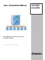
User & Installation Manual
Farm Master and Farm Center Pig
controller system
HC/MIT/UmGB-1557-05/09 © Munters Europe AB 2009
CCL5020
CCL5050
Farm Master & Farm Center
Disclaimer
Munters reserves the right to make alterations to specifications, quantities, dimensions etc. for
production or other reasons, subsequent to publication.
The information contained herein has been prepared by qualified experts within Munters.
While we believe the information is accurate and complete, we make no warranty or
representation for any particular purposes. The information is offered in good faith and with the
understanding that any use of the units or accessories in breach of the directions and warnings
in this document is at the sole discretion and risk of the user.
HC/MIT/UmGB-1557-05/09
© Munters Europe AB, 2009
Farm Master & Farm Center User & Installation manual for pigs
Munters reserves the right to make alterations to specifications, quantities, etc. for production or other reasons, subsequent to publication.
2(61)
Farm Master & Farm Center
WARRANTY & LIMITATION OF LIABILITY
1. MUNTERS warrants that the product shall be free of defects in materials or workmanship and will
conform to the technical specification for a period of 1 (one) year from the date of initial installation on
sight (the "warranty period").
2. Load cells are not covered by MUNTERS’s warranty.
3. MUNTERS warrants that during said warranty period, any item/items or part/parts of equipment found
defective with respect to materials or workmanship or which do not conform to the technical specification
shall be repaired or replaced (at MUNTERS's sole discretion), free of charge.
4. During the warranty period, in the event of an alleged defect, authorized resellers in relevant regions
should be notified as soon as possible from the date of noticing the said defect, but no longer than thirty
(30) days from such a discovery. The report shall include (1) a short description of the defects noticed (2)
type of card / component and its matching serial number.
5. MUNTERS's sole liability under this warranty is the repair or replacement of the defective item of
product.
Conditions and Limitations
1. MUNTERS will not be responsible for any labor costs or expenses associated with replacement of
defective items or other parts of the product or repair.
2. This warranty shall not cover: (i) product or part therein which has been modified (without prior
written approval of MUNTERS), or (ii) product or part therein which has not handled or installed by
an authorized reseller of MUNTERS or (iii) product or part therein which has either handled or
installed not in strict accordance with MUNTERS's instructions, (iv) products which were used for
function other than agriculture industry.
3. This warranty will not apply in the following cases: (i) if all components of the product are not
originally supplied by MUNTERS (ii) the defect is the result of an act of nature, lighting strikes,
electrical power surge or interruption of electricity (iii) the defect is the result of accident, misuse,
abuse, alteration, neglect, improper or unauthorized maintenance or repair.
MUNTERS warns and alerts all users that the Product is inherently complex and may not be
completely free of errors. MUNTERS's products are designed and manufactured to provide reliable
operation. Strict tests and quality control procedures are applied to every product. However, the
possibility that something may fail beyond our control exists. Since these products are designed to
operate climate control and other systems in confined livestock environments, where failure may
cause severe damage, the user should provide adequate backup and alarm systems. These are to
operate critical systems even in case of a MUNTERS system failure. Neglecting to provide such a
backup will be regarded as the user’s willingness to accept the risk of loss, injury and financial
damage.
In no event will MUNTERS be liable to a user or any third party for any direct, indirect, special,
consequential or incidental damages, including but not limited to any damage or injury to business
earnings, lost profits or goodwill, personal injury, costs of delay, any failure of delivery, costs of lost
or damaged data or documentation, lost or damaged products or goods, lost sales, lost orders, lost
income.
Except for the above express warranty, MUNTERS makes no other warranties, express or implied,
relating to the products. MUNTERS disclaims and excludes the implied warranties of merchantability
and fitness for a particular purpose. No person is authorized to make any other warranty or
representation concerning the performance of the products other than as provided by MUNTERS.
Software Version:
1.3
Document Version:
2.1
Munters. Italy S.P.A +39 0183 521364 FAX: +39 0183 521333 Italy
HC/MIT/UmGB-1557-05/09
© Munters Europe AB, 2009
Farm Master & Farm Center User & Installation manual for pigs
Munters reserves the right to make alterations to specifications, quantities, etc. for production or other reasons, subsequent to publication.
3(61)
Farm Master & Farm Center
Table of Contents
Support Information
7
Explanation of Symbols and Manual Elements
7
Introduction
8
Components
8
General Description
8
Features
10
Getting Started
.................................................................................... 11 5 Step Installation Guide
11
Farm-Center Keyboard
12
Farm-Center Main-screen
13
Hotkeys
15
Farm-Center Setup
.................................................................................... 18
1
.............................................................................20
CONTROL
Temp Curve
20
Min. Max. Level
20
Humidity
23
Static Pressure
24
SystemParameters
25
Control Mode
28
2
DEVICE
.............................................................................29
Vent Levels
29
Var. Fan Levels
31
Curtain Levels
32
Circulation Fan
33
Cool Pad
34
Foggers
35
Light
36
Feed
36
Extra System
36
Time Clocks
37
Variable Heat
38
HC/MIT/UmGB-1557-05/09
© Munters Europe AB, 2009
Farm Master & Farm Center User & Installation manual for pigs
Munters reserves the right to make alterations to specifications, quantities, etc. for production or other reasons, subsequent to publication.
4(61)
Farm Master & Farm Center
3
MANAGEMENT .............................................................................39
Animal Inventory
39
Day & Group
39
Alarm setting
40
Alarm Reset
41
Version
41
Read From Plug
41
Write To Plug
42
4
HISTORY
.............................................................................43
Temperature
43
Humidity
43
Water
43
Feed
44
Mortality
44
Heater
44
Alarm
45
Event
46
5
CALIBRATION
.............................................................................47
Temperature
47
Humidity
47
Pressure
47
Water & Feed
47
6
INSTALLATION .............................................................................48
Relay Layout
48
Sensors Layout
49
Digital Input
49
Analog Output
49
Variable Speed Fan
50
Sensor Definition
50
Curtain Setup
50
HC/MIT/UmGB-1557-05/09
© Munters Europe AB, 2009
Farm Master & Farm Center User & Installation manual for pigs
Munters reserves the right to make alterations to specifications, quantities, etc. for production or other reasons, subsequent to publication.
5(61)
Farm Master & Farm Center
Farm-Masters
.............................................................................51
Cold Start
51
Set Unit Number
51
Main Menu
51
Calibration
52
Test
52
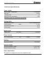
Technical Specifications
53
Farm-Master Installation Guide.
54
Mechanical Installation Guide
56
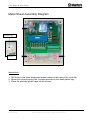
Metal Sheet Assembly Diagram
57
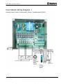
Farm Master Wiring Diagram 1
59
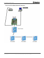
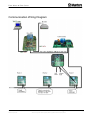
Communication Wiring Diagram
60
HC/MIT/UmGB-1557-05/09
© Munters Europe AB, 2009
Farm Master & Farm Center User & Installation manual for pigs
Munters reserves the right to make alterations to specifications, quantities, etc. for production or other reasons, subsequent to publication.
6(61)
Farm Master & Farm Center
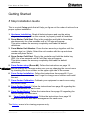
General
This manual will help you get the most out of your new MUNTERS controller.
Please read the manual before installing and configuring your Farm-Center /
Farm-Master system.
Support Information
Using this equipment for any other purpose or in a way not within the operating
recommendations specified in this manual will void the warranty and may cause
personal injury.
Explanation of Symbols and Manual Elements
Cautions alert you of potential damage to the controller,
if the procedures are not followed carefully.
Dangers alert you of potentially hazardous situations
which, if not avoided could result in death or personal
injury.
Notes contain important "tips" and additional information
you should know.
HC/MIT/UmGB-1557-05/09
© Munters Europe AB, 2009
Farm Master & Farm Center User & Installation manual for pigs
Munters reserves the right to make alterations to specifications, quantities, etc. for production or other reasons, subsequent to publication.
7(61)
Farm Master & Farm Center
Introduction
This manual provides easy-to-use information for installation, operation, long/short
term planning and parts listing. The table of contents is an outline of the relevant
information in this manual.
Read this manual before operating your MUNTERS Controller.
If you have any questions or comments regarding your controller please contact
your local MUNTERS dealer.
Components
-
Farm-Center
Farm-Master
Extension Box (optional)
MUX 485 Communication (optional)
General Description
Farm-Center
The Farm-Center provides you maximum capability with minimal complexity in
programming and controlling up to 10 Farm-Master units.
The Farm-Center provides you maximum capability with minimal complexity in
programming and controlling up to 10 units.
Farm-Center is the ultimate pig house controller. Equipped with an easy programming
interface, it provides programmable outputs for all major features and a 4x20 character
LCD that provides display feedback on the programming and device status.
The Farm-Center communicates with up to ten Farm-Master units to access history,
collect events and alarms for each and all relevant data up to 100 days.
HC/MIT/UmGB-1557-05/09
© Munters Europe AB, 2009
Farm Master & Farm Center User & Installation manual for pigs
Munters reserves the right to make alterations to specifications, quantities, etc. for production or other reasons, subsequent to publication.
8(61)
Farm Master & Farm Center
Farm-master
Farm-master is MUNTERS’s latest advance in environmental controllers specially
designed for the pig house industry.
The user-friendly has high performance and quick response time. Farm-master features
accurate temperature and humidity sensors, secure transmission of data even in noisy
environments and the added convenience of eight output relays as well as four analog
outputs.
Each Farm-master can operate independently, in case of Farm-center malfunction or
loss of power. Using an internal battery when the Farm-master is operating “alone”, there
is no history collection or possibility to change parameters.
HC/MIT/UmGB-1557-05/09
© Munters Europe AB, 2009
Farm Master & Farm Center User & Installation manual for pigs
Munters reserves the right to make alterations to specifications, quantities, etc. for production or other reasons, subsequent to publication.
9(61)
Farm Master & Farm Center
Features
Farm-Center
Easy programming
LCD - 4x20 characters
Positioning scrollbar
Swift device and feature selection
Data plug
Large numeric keypad
Communication with up to ten Farm-Master units.
Extensive history of events & alarms
Data Collection
Real time visual outlook
Alarm system (for every Farm-Master unit)
Multi language Support.
PC communication
Farm-master
Easy programming
Programmable outputs
Alarm system
Large display
Up to 3 temperature sensors
Up to 8 heavy duty relays (1 HP)
On/Off/Auto override switches
Static pressure control (optional)
4 Analog output (0-10 volts)
Variable speed fan output with bypass
Water, feed, and humidity control
Automatic calibration of curtains
HC/MIT/UmGB-1557-05/09
© Munters Europe AB, 2009
Farm Master & Farm Center User & Installation manual for pigs
Munters reserves the right to make alterations to specifications, quantities, etc. for production or other reasons, subsequent to publication.
10(61)
Farm Master & Farm Center
Getting Started
5 Step Installation Guide
This is a quick 5 step guide that will help you figure out the order of actions for a
proper system installation:
1. Hardware Installation: Read all technical specs and use the wiring
diagrams, from page 53 on this manual, to properly install all hardware.
2. Farm-Master Cold Start: Plug in the controller and hold its three keys
simultaneously for a few seconds until a CLD sign will appear.
This action erases the memory completely and loads the default
definitions.
3. Farm-Master Unit Number: Press the two arrow keys together until the
number sign (no.) blinks. Select the unit number with the up and down
arrows and press Select.
4. Farm-Center Cold Start: Plug in the controller and hold the delete key
(DEL) for a few seconds until a Cold Start sign will appear.
This action erases the memory completely and loads the default
definitions.
5. Farm-Center setup (Room #0): Follow the instructions on page 18.
Before making any changes make sure you are changing the correct room
by checking the room number on the upper right side of the screen.
6. Farm-Center Installation: Follow the instructions from page 48. If you
have more than one room, don’t forget to change room number and install
the rest.
7. Farm-Center Calibration: Calibrate your equipment on each room using
the service menu.
8. Farm-Center Control: Follow the instructions from page 20 regarding the
control parameters for each room.
9. Farm-Center Device: Follow the instructions from page 29 regarding the
device settings for each room.
10. Farm-Center Management: Follow the instructions from page 39
regarding live stock and alarm management for each room.
The History menu is for viewing purposes only.
HC/MIT/UmGB-1557-05/09
© Munters Europe AB, 2009
Farm Master & Farm Center User & Installation manual for pigs
Munters reserves the right to make alterations to specifications, quantities, etc. for production or other reasons, subsequent to publication.
11(61)
Farm Master & Farm Center
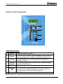
Farm-Center Keyboard
B
A
C
D
E
F
G
Keyboard Functions
A
Menu
B
Room
C
Arrows
D
E
Round
Arrows
Enter
F
Numeric
Pad
G
Delete
HC/MIT/UmGB-1557-05/09
© Munters Europe AB, 2009
Toggles the menu function
The room key is used to switch between rooms. Press the
room key and press a number to reach the desired room.
Use the arrows to scroll a short press in any direction
moves one notch.
The Round Arrows key is used to scroll between options
(Yes/No, On/Off and '-').
The enter key is a confirmation key.
The Number keys are selected when a numeric choice is
done and when numbers should be selected. Moreover,
those keys are used for Hot Keys purposes.
The 'Delete' key erases typing mistakes.
Farm Master & Farm Center User & Installation manual for pigs
Munters reserves the right to make alterations to specifications, quantities, etc. for production or other reasons, subsequent to publication.
12(61)
Farm Master & Farm Center
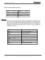
Farm-Center Main-screen
TEMP
27.1
ROOM
RH%
75.0
DAY
TRGT
24.0
Hr.
RH%T
80.0
LEVEL
#01
1
13:21
1
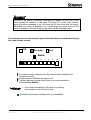
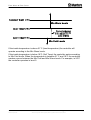
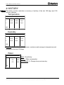
The main screen shows basic information regarding rooms controlled by the
Farm-Center, depending on what equipment is plugged in. Other parameters
like static pressure (PRESS), outside temperature (OUT), level, message and
offset are also shown on the main screen when they are plugged in.
Parameters are shown according to priority. There is a square in level line
indicating tunnel level.
TEMP
Current room temperature
RH%
Current room humidity
TRGT
Target temperature
RH%T
Target humidity
OUT
Outside Temp.
ROOM
DAY
#01
Room number
Growth day
Hr.
Time
LEVEL
Current ventilation level.
HC/MIT/UmGB-1557-05/09
© Munters Europe AB, 2009
Farm Master & Farm Center User & Installation manual for pigs
Munters reserves the right to make alterations to specifications, quantities, etc. for production or other reasons, subsequent to publication.
13(61)
Farm Master & Farm Center
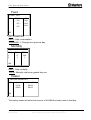
In case of an alarm, a blinking message will appear on any one of the
main screens in addition to the siren. Pressing "0" on the main screen,
when the alarm message is on, will direct you to the room with the alarm.
Resetting the alarm is possible, but it only stops the siren and not the
screen message. Only by fixing the problem will the message stop.
Pressing the zero on the numeric pad, while the alarm is activated will open
the room status screen.
O.K
No com.
N/A
Alarm
1
2
3
4
5
6
7
8
9
10
An empty square indicates that the Farm-Center identifies the
houses correctly.
A filled square indicates an alarm is on.
A dotted square indicates that there is no communication
with the Farm-Master.
Once communication is off there is no history
accumulation in the Farm-Center.
A dotted lined square indicates N/A (not available).
HC/MIT/UmGB-1557-05/09
© Munters Europe AB, 2009
Farm Master & Farm Center User & Installation manual for pigs
Munters reserves the right to make alterations to specifications, quantities, etc. for production or other reasons, subsequent to publication.
14(61)
Farm Master & Farm Center
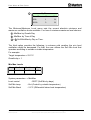
Hotkeys
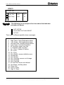
To reach the Hotkeys screens, press the Hotkey number while viewing the main
screen. The room number is located on the upper right side of the Hot screen to
view the status of deferent rooms, first enter the desired room using the room key
and pressing the room number. Then press the desired screen Hotkey number.
Hot key 1 - Main screen
Hot key 2 - Temperature screen
The temperature hot screen shows important information regarding the status of
temperature sensors attached to the Farm-Center. The average temperature
(defined in table 6.6) is displayed on the upper left side and shows the average of
temperature sensors T1 through T3. Table 6.2 enables the user to set the
temperature sensor T3 as 'OUT' and therefore T3 presents the outside temperature.
On the right side, you can see the temperature for entering tunnel ventilation mode.
T1
T2
T3
24.4
25.1
22.5
#01
AVG.
TUN.
OUT
22.9
23.3
22.5
Room Number
Hot key 3 – Targets Screen
TARGETS
#01
TEMP
22.5
PRESS 0.01
MIN LEVEL
5
ON
60
MAX LEVEL 15
OFF
240
This screen shows all of the target
levels, selected for any of the
controller's functions.
Hot key 4 - Curtain Position screen
This screen shows the curtain opening position in percent. If for example curtain 2
show 40%, it is 40% open.
CURTAIN POSITION
CURT.1
50
CURT.2
CURT.3
40
CURT.4
TUNNEL
OP
INLET
HC/MIT/UmGB-1557-05/09
© Munters Europe AB, 2009
#01
CL
---
Farm Master & Farm Center User & Installation manual for pigs
Munters reserves the right to make alterations to specifications, quantities, etc. for production or other reasons, subsequent to publication.
15(61)
Farm Master & Farm Center
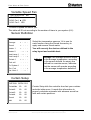
Hot key 5 - Curtain Steps
CURTAIN STEPS
CURT.1
12
CURT.2
CURT.3
14
CURT.3
TUNNEL
-INLET
#01
----
This screen shows the number of
steps for each curtain.
Hot key 6 - System Status
This screen shows if humidity
SYSTEM STATUS
#01
HUMIDITY TREAT.
ON/OFF
CYCLE STATUS
ON/OFF
CYCLE LEFT
29
treatment is ON/OFF, if the cycle is
ON/OFF and how many seconds left
for the current cycle.
Hot key 7 - Variable Fans
This screen shows the speed percent
FAN 1
FAN 2
VARIABLE FANS
30%
FAN 3
40%
FAN 4
#01
n/a
n/a
of each variable fan.
Hot key 8 - Variable Heat
This screen shows the percent of
VARIABLE HEAT
HEAT 1
70%
HEAT 2
n/a
#01
each variable heat.
Hot key 9 - Relay Status
This option shows active relays, pressing 9 again will open the extension box's
relay activity
RELAY STATUS
#01
R1- R2- R3- R4-
R5- R6- R7- R8-
EXTENSION RELAYS '9'
HC/MIT/UmGB-1557-05/09
© Munters Europe AB, 2009
Relay Active
Relay Not Active
Farm Master & Farm Center User & Installation manual for pigs
Munters reserves the right to make alterations to specifications, quantities, etc. for production or other reasons, subsequent to publication.
16(61)
Farm Master & Farm Center
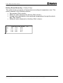
Hot key Round Arrow key – History Temp.
This option shows a summary of temperature according to temperature room. This
screen consists of the following columns;
Day number ('Day' column)
Minimum value measured on that day ('Min' column)
Average value calculated on the measured temperatures through the whole
day ('Avg' column)
Maximum value measured on that day ('Max' column)
DAY
23
24
TEMPERATURE ROOM
MIN AVG
MAX
21.4 23.5
24.5
21.8 24.6
24.7
HC/MIT/UmGB-1557-05/09
© Munters Europe AB, 2009
#1
Farm Master & Farm Center User & Installation manual for pigs
Munters reserves the right to make alterations to specifications, quantities, etc. for production or other reasons, subsequent to publication.
17(61)
Farm Master & Farm Center
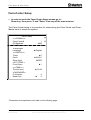
Farm-Center Setup
• In order to reach the Farm-Center Setup screen go to:
Room key, then press '0' and "Enter" from any of the main screens.
The Farm-Center setup is a procedure for customizing the Farm-Center and FarmMaster units to match the system.
Farm-Center
===COMM.===
Farm-Center#
PC.Baudrate
Total Rooms
=Language=
Language
===UNITS===
Temp.
Press
Other Units
=OUT TEMP.=
From Room
===TIME===
Time(hh:mm)
=PASSWORD=
Full Access
Read Only
1
4800
5
►English
►F
►IN.W.C
IMPER
►1
►12:06
►
0
0
*Parameters are explained in the table on the following page.
HC/MIT/UmGB-1557-05/09
© Munters Europe AB, 2009
Farm Master & Farm Center User & Installation manual for pigs
Munters reserves the right to make alterations to specifications, quantities, etc. for production or other reasons, subsequent to publication.
18(61)
Farm Master & Farm Center
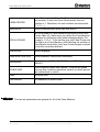
FARM-CENTER
Farm-Center identity (Max-32). Define the Farm-Center's
unit number. If only one Farm-Center exists, the unit
number is 1. Otherwise, the unit numbers are sequential
(1, 2, 3,…).
BAUDRATE
Select communication baud rate with the PC.
TOTAL ROOMS
Set the number of Farm-Masters connected to the FarmCenter (Max-10). Make sure you define the Farm-Masters'
numbers in a following order without skipping digits. For
example: 1,2,3,4... If not set this way, the Farm-Center will
not detect any Farm-Masters. After defining the number of
Farm-Master controllers, the Farm-Center begins a search
to find the controllers defined.
LANGUAGE
Select language.
TEMPERATURE UNIT
Select between Celsius and Fahrenheit.
PRESSURE
Select between: Milibar, IN.W.C, Pascal, CM.W.C,
MM.W.C.
OTHER UNIT
Select between meter and imperial. Controls the speed
and rain flow. Units for speed are meter/h or mile/h and for
rain millimeter/h or inch/h.
TIME
Set clock time.
PASSWORD
Set password to protect data.
The last six parameters are general for all of the Farm-Masters.
HC/MIT/UmGB-1557-05/09
© Munters Europe AB, 2009
Farm Master & Farm Center User & Installation manual for pigs
Munters reserves the right to make alterations to specifications, quantities, etc. for production or other reasons, subsequent to publication.
19(61)
Farm Master & Farm Center
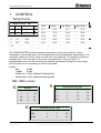
1
CONTROL
Temp Curve
TEMP CURVE
#01
#
1
Day
1
Target
23.3
Heat
21.1
Tunnel
37.2
Low Alarm
21.1
High Alarm
37.2
2
14
22.2
20.0
37.2
10.0
35.0
3
42
21.1
18.8
32.2
10.0
35.0
4
70
20.5
17.8
29.4
10.0
35.0
5
98
20.0
16.6
26.6
10.0
32.2
..10
The FARM-MASTER provides separate temperature curves for growth day, target
temperature, heat temperature, tunnel temperature and low/high alarm temperatures. The
controller creates a curve for each one and uses it as reference. The program will alter at
midnight prior to the next day on the next row programmed. There are up to 10
programmable rows, but the controller will maintain yesterday’s settings for every empty
line, therefore it is not necessary to fill the entire table.
Limits:
Day
0-999
Target
0-40c
Alarm low 0-40c (without floating point)
Alarm high 0-40c (without floating point)
Min. Max. Level
2
1 Soft Minimum By Day
By Day
Day
Min
Max
1
1
21
14
3
30
98
9
30
3 © Munters Europe AB, 2009
Min Cold
Min Warm
Max
1
1
11
25
14
3
13
30
98
9
19
30
Soft Minimum By Time
From Time
HC/MIT/UmGB-1557-05/09
Day
Min Cold Min Warm
Max
8:00
1
7
25
20:00
3
5
23
Farm Master & Farm Center User & Installation manual for pigs
Munters reserves the right to make alterations to specifications, quantities, etc. for production or other reasons, subsequent to publication.
20(61)
Farm Master & Farm Center
4 By Time
From Time
Min
Max
8:00
1
21
20:00
3
21
The Minimum/Maximum Level menu sets the current absolute minimum and
maximum ventilation levels available. You have 4 minimum maximum level choices:
1 Min/Max by Growth Day
2 Min/Max by Time of Day
3 + 4 Soft Min/Max by Day or Time.
The third option provides the following; in extreme cold weather the min level
ventilation might be decreased. For that, the user utilizes the Soft Min level that
operates according to outside or inside temperature.
For example:
Target temperature = 23.3°C
Growth day = 1
Min Max Levels
Day
Min Cold
Min Warm
Max
1
1
10
30
System parameters -> Min/Max
Level control
- DSFT (Soft Min by days)
Soft Min temp
- Out (Control by outside temperature)
Soft Min Band
- 2.2°C (Differential below heat temperature)
HC/MIT/UmGB-1557-05/09
© Munters Europe AB, 2009
Farm Master & Farm Center User & Installation manual for pigs
Munters reserves the right to make alterations to specifications, quantities, etc. for production or other reasons, subsequent to publication.
21(61)
Farm Master & Farm Center
If the inside temperature is above 21°C (heat temperature) the controller will
operate according to the Min Warm levels.
If the inside temperature is below 19°C (Soft Temp) the controller works according
to Min Cold levels. When the temperature is between 21°C and 19°C the controller
creates a curve between the Min Cold and Min Warm levels. For example, in 20°C
the controller operates in level 5.
HC/MIT/UmGB-1557-05/09
© Munters Europe AB, 2009
Farm Master & Farm Center User & Installation manual for pigs
Munters reserves the right to make alterations to specifications, quantities, etc. for production or other reasons, subsequent to publication.
22(61)
Farm Master & Farm Center
Important:
When using Soft Min according to inside temperature there is a curve
between min warm and min cold, while decreasing levels. When temperature
increases the level remains at the lowest level reached, until reaching the
heat temperature.
When using Soft Min according to outside temperature there is a curve
between min warm and min cold while decreasing and increasing levels.
To select the type of minimum/maximum go to system parameters and
change the level control (see page 21).
Humidity
HUMIDITY
#01
Target
Delay (minute)
Duration (sec)
0
0
0
Band (%)
Below Heat
2
NO
Target: Set the humidity target for.
Delay: delay time before humidity treatment. The controller checks during the delay
time whether the humidity is above the target.
Duration: humidity treatment duration time.
Band: band zone to balance the treatment.
Below heat: select if you wish to initiate humidity treatment below heater
temperature.
HC/MIT/UmGB-1557-05/09
© Munters Europe AB, 2009
Farm Master & Farm Center User & Installation manual for pigs
Munters reserves the right to make alterations to specifications, quantities, etc. for production or other reasons, subsequent to publication.
23(61)
Farm Master & Farm Center
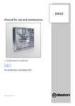
Static Pressure
STATIC PRESSURE
Out Temp low: Set outside low temperature
definition for low pressure target.
#01
Out temp low
Press. (low t)
Out temp high
5
0.08
35
Press (Low T): Static pressure target for the
outside low temperature (See graph below,
point 1).
Press. (high t)
Tunnel press.
Low alarm
High alarm
Band
Wind delay (s)
Pre open (s)
Alarm MINIMUM level
0.12
0.08
0.05
0.15
0.04
10
5
0
Out Temp High: set outside high
temperature definition for high pressure
target.
Press (High T): Static pressure target for
outside high temperature (See graph below,
point 2).
Tunnel Pressure: Static pressure target
during tunnel ventilation mode.
Low Alarm: If static pressure drops below set point alarm will be active.
High Alarm: If static pressure rises above set point alarm will be active.
Band: Set band zone to balance the system.
Wind Delay: Static pressure is affected by wind, this definition is to ensure that an
alarm is given due to a stable change in pressure and not an accidental one, that
may have been caused by a wind gust.
High Alarm
Pressure
1
Tunnel Pressure
2
Static Pressure
Low Alarm
Temp
Pre Open: Time setting for curtains to open before fans activate. This is to make sure the
curtains are open before fan activity.
Alarm minimum level: from what level you wish to activate low static pressure alarm.
HC/MIT/UmGB-1557-05/09
© Munters Europe AB, 2009
Farm Master & Farm Center User & Installation manual for pigs
Munters reserves the right to make alterations to specifications, quantities, etc. for production or other reasons, subsequent to publication.
24(61)
Farm Master & Farm Center
SystemParameters
SYSTEM PARAMETERS
==TEMP==
Offset: Use this parameter to change the offset target
temperature up or down for any purpose.
Default: 0.0
Band: this refers to the target temperature zone
range. The User’s Manual refers to this as the Happy
Zone.
Default: 1.0
Cool Factor (%): the minimum correction towards
target happy zone during each increase ventilations
delay (patience factor). If the temperature does not
improve by this amount, the controller will increase
one level.
Default: 10%
Cold Above TRG: Temp Change To Be Considered
As Quick Drop In Degrees, To Reduce A Level To
Reach Above Target Temp (Degrees).
Default: 3.0
Cold Below TRG: Temp Change To Be Considered
As Quick Drop In Degrees, To Reduce A Level To
Reach Below Target Temp (Degrees).
Default: 1.0
==HEATER==
Heat Band: Set the happy zone for the heaters on/off.
Default: 1.0
Heat Lamp Diff: differential from target temperature to
initiate heat lamps.
Default: 0.0
Heat Offset: Use this parameter to change the offset
Heat temperature up or down for any purpose.
Default: 0.0
HC/MIT/UmGB-1557-05/09
© Munters Europe AB, 2009
=====TEMP=====
Offset
► 0.0
Band
1.0
Cool Factor
10%
Cold Above TRG
3.0
Cold Below TRG
1.0
====HEATER====
Heat Band
1.0
Heat Lamp Diff
0.0
Heat Offset
0.0
====MIN MAX====
Curve
NO
Level Control
Day
Soft Min Temp
OUT
Soft Temp Band
10.0
====PRESSURE====
Press Control
NO
====LEVELS====
Inc Delay (s)
180
Dec Delay (s)
120
====TUNNEL====
1st Tun Level
0
Dif Below, Exit
2.0
T.Out Dif, Exit
18.0
Exit Delay (m)
5
===CURTAINS===
Calib Steps
99
==COOL PAD==
From Level
0
Temp Band
1.0
Humidity Band%
2.0
===FOGGERS===
From Level
0
Temp Band
1.0
Humidity Band%
2.0
===VAR. FAN===
Freeze Protect
NO
Min Fan 1 Spd%
30
Min Fan 2 Spd%
30
Min Fan 3 Spd%
30
Min Fan 4 Spd%
30
Farm Master & Farm Center User & Installation manual for pigs
Munters reserves the right to make alterations to specifications, quantities, etc. for production or other reasons, subsequent to publication.
25(61)
Farm Master & Farm Center
==MIN MAX==
Curve: If Yes - Min max table curve between the days.
Default: NO - Will work according to previous line until current day.
Level Control: Four options for the min max table method: by days, soft
minimum by days, by time, soft minimum by time.
Default: Day
Soft Min Temp: choice whether to use the current inside temperature or the
outside temperature to determine when to use the soft minimum.
Default: OUT
Soft Temp Band: diff below heat temperature to set temperature at which to
enforce low temperature minimum ventilation level.
Default: 10.0
==PRESSURE==
Press Control (Yes / No): If a pressure control should be done in Min Vent mode
by the inlet and in Tunnel mode by tunnel curtain, select Yes. Otherwise, select
No.
Default: No.
==LEVELS==
Inc Delay Time: this is the standard minimum delay before increasing ventilation
levels.
Default: 120 (sec)
Dec Delay Time: this is the standard minimum delay before decreasing
ventilation levels.
Default: 180 (sec)
HC/MIT/UmGB-1557-05/09
© Munters Europe AB, 2009
Farm Master & Farm Center User & Installation manual for pigs
Munters reserves the right to make alterations to specifications, quantities, etc. for production or other reasons, subsequent to publication.
26(61)
Farm Master & Farm Center
==TUNNEL==
1st Tunnel Level: switching into and out of tunnel ventilation is a major change in
ventilation. For tunnel ventilation, enter the first tunnel level here. If set on 0 there
is no tunnel level.
Default: 0
Dif Below, Exit: this parameter sets amount below the tunnel entry temperature
at which to exit tunnel ventilation. Tunnel temperatures are determined by the
sensors specified in Temperature Definition. Entry and exit is also controlled by
these sensors. The controller can not exit tunnel until the tunnel temperature is
this much less than the tunnel entry temperature. It must be a positive number.
Default: 2.0
T.Out Dif, Exit: set the relative temperature for the outside sensor at which to exit
tunnel. The controller can not exit tunnel until the outside temperature is less than
tunnel temperature plus this differential. This number can be positive or negative.
To eliminate the effect of this parameter on tunnel exit, enter a large positive
number such as 90.0.
Default: 0.0
Exit Delay (m): delay time after satisfying tunnel exit conditions.
Default: 5 (minutes)
==CURTAINS==
Calibration Steps: to ensure accurate positioning of the curtains, the controller
may periodically calibrate the curtain position. This parameter sets the maximum
number of curtain movements or stages between calibrations. Calibration
consists of forcing the curtain to the nearest limit, 0% or 100% with adequate
overtime to ensure reaching the limit switch. Then the curtain returns to its proper
position. In the event several curtains require calibration, they calibrate one at a
time to reduce the amount of restriction to normal ventilation. The stage counter
resets automatically each time the curtains reach a limit point to prevent
excessive calibration.
Default: 99
==COOL PAD==
From Level: from what ventilation level to begin cool pad operation. 0 is no
operation.
Default: 0
Temp Band: on/off differential or Happy Zone with respect to temperature for the
‘Cool #’ and ‘Cool Pad #’ relays. These normally control the water pump for the
cool cells.
Default: 1.0
Humidity Band: on/off differential or Happy Zone with respect to inside humidity
for the ‘Cool #’ and ‘Cool Pad #’ relays.
Default: 2.0
HC/MIT/UmGB-1557-05/09
© Munters Europe AB, 2009
Farm Master & Farm Center User & Installation manual for pigs
Munters reserves the right to make alterations to specifications, quantities, etc. for production or other reasons, subsequent to publication.
27(61)
Farm Master & Farm Center
==FOGGER==
From Level: from what ventilation level to begin fogger operation. 0 is no
operation.
Default: 0
Temp Band: See cool pad above.
Default: 1.0
Humidity Band: See cool pad above.
Default: 2.0
==VAR. FAN==
Freeze Protect: A general protection for the variable speed fan motor.
When the variable speed fan starts from zero speed, the freeze
protection activates it to 100% for 5 seconds.
Default: No
Min Motor1,2,3,4 Spd: Safety speed fan operation delay. This is the Fan
minimum speed to begin operation.
Default: 30.
Control Mode
CONTROL MODE
Set Mode
#01
►Normal
Empty
In this screen control mode can be set, choosing between Normal mode and
Empty mode.
EMPTY MODE
Empty mode is applied in cases of empty houses.
When Empty mode is selected:
All alarms will be disabled
A flashing massage will appear while displaying temperature.
"E" In Farm-Master and "Empty House" in Farm-Center.
Setting controller to Normal or Empty mode will insert an event to History/Event
table
HC/MIT/UmGB-1557-05/09
© Munters Europe AB, 2009
Farm Master & Farm Center User & Installation manual for pigs
Munters reserves the right to make alterations to specifications, quantities, etc. for production or other reasons, subsequent to publication.
28(61)
Farm Master & Farm Center
2 DEVICE
Vent Levels
VENT LEVELS
#
12345678
#01
on
Off
Diff
01
30
240
0
02
40
220
0
30
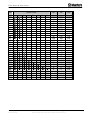
The Farm-Center provides up to 30 programmable ventilation levels. The usual way
to program them is to start the first level with the least amount of air to be used.
The full circles represent continuous fan operation.
The half full circle represents cycle operations according to the on/off time set for
each stage.
A dot represents no operation at all.
The following table is an example of a proper ventilation setting.
Note that tunnel is not noticeable on the current table and is set according to the
system parameter- 1st tunnel level.
HC/MIT/UmGB-1557-05/09
© Munters Europe AB, 2009
Farm Master & Farm Center User & Installation manual for pigs
Munters reserves the right to make alterations to specifications, quantities, etc. for production or other reasons, subsequent to publication.
29(61)
Farm Master & Farm Center
Lev
Tunnel Fans
1
2
3
1
2
3
4
5
6
7
8
9
10
11
12
13
14
15
16
17
18
19
20
21
22
23
24
25
26
27
28
29
30
HC/MIT/UmGB-1557-05/09
© Munters Europe AB, 2009
4
5
6
7
On
Off
Diff
30
40
52
70
90
30
40
52
70
90
120
160
225
300
100
70
90
120
160
225
0
0
0
0
0
0
570
560
548
530
510
270
260
248
230
210
180
140
75
0.0
0.0
0.0
0.0
0.0
0.0
0.0
0.0
0.0
0.0
0.0
0.0
0.0
0.0
0.0
0.0
0.0
0.0
0.0
0.0
0.0
1.0
2.0
3.0
4.0
5.0
8
200
230
210
180
140
75
0
0
0
0
0
0
Farm Master & Farm Center User & Installation manual for pigs
Munters reserves the right to make alterations to specifications, quantities, etc. for production or other reasons, subsequent to publication.
30(61)
Farm Master & Farm Center
Var. Fan Levels
SPEED (%)
#01
#
Fan 1
Fan 2
01
02
30
20
32
25
Fan 3
0
0
Fan 4
0
0
…30
The percentage for a full circle represents the fan operation percentage form the
maximum. If set on 30% it will operate up to 30% of the maximum.
The percentage for a half full circle represents the fan operation percentage in off
mode during cycle operation. The fan will operate at 100% at on time.
If set on 20%, the fan will operate at 20% of the full power during off time in the
cycle and will increase to 100% at on time.
HC/MIT/UmGB-1557-05/09
© Munters Europe AB, 2009
Farm Master & Farm Center User & Installation manual for pigs
Munters reserves the right to make alterations to specifications, quantities, etc. for production or other reasons, subsequent to publication.
31(61)
Farm Master & Farm Center
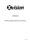
Curtain Levels
CURTAIN (%)
#01
#
Crt. 1
Crt. 2
Crt. 3
Crt. 4
Tun.
inlet
01
02
0
0
0
0
0
0
0
0
0
0
15
15
…3
0
0
0
0
0
0
15
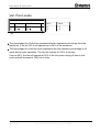
Curtain Level Example
Curtain (% Open)
Level
Set the curtain levels to correspond with
the ventilation levels. Some producers will
want to open the tunnel curtain somewhat
prior to the actual tunnel. This is
convenient to control pressure in retrofit
houses which may not have sufficient
side inlets for the number of fans required
in side ventilation.
You can also optionally run the tunnel
curtain under pressure control. In that
event, the percent open settings become
minimum settings. Then, once the side
vents are at 100%, if pressure requires,
the Master will open the tunnel curtain to
maintain the pressure setting.
HC/MIT/UmGB-1557-05/09
© Munters Europe AB, 2009
1
2
3
4
Tunnel
Inlet
0
0
0
0
0
15
.
.
.
.
.
.
.
.
.
.
.
.
.
.
.
.
.
.
0
0
0
0
0
15
18
0
0
0
0
30
19
0
0
0
0
45
20
0
0
0
0
70
21
0
0
0
0
100
22
0
0
0
0
100
23
0
0
0
0
100
24..30
0
0
0
0
0
Levels
1 thru
17
Farm Master & Farm Center User & Installation manual for pigs
Munters reserves the right to make alterations to specifications, quantities, etc. for production or other reasons, subsequent to publication.
32(61)
Farm Master & Farm Center
Circulation Fan
CIRCULATION FAN
#01
Sensors Dif
From Time
3.0
00:00
To Time
From Level
To Level
00:00
1
10
The circulation fans will mix the air inside the house and control temperature
differentials between different parts of the house.
Sensors Dif: the circulation fan will start if the difference between temperatures in
different parts of the house will be higher then the set differential. The sensors that
participate in this differential can be divided in to 3 groups:
1. If no sensors are set for circulation fans in temp definition, the current defined
sensors will control this operation. If for example the house is in tunnel mode,
the tunnel sensors will control the circulation fans. If there will be difference
higher then 3 (like the example above) between 2 sensors the circulation fans
will begin to operate.
2. If one sensor is defined for the circulation fans, the difference between this
sensor and the average will control the circulation fans.
3. if more then one sensor is defined for the circulation fans, when the
difference increase between any 2 sensors, the circulation fans will begin
operation.
From Time: from what time to start the application.
To Time: to what time operate this application.
From Level: from what level to operate this application.
To Level: up to what level operate this application.
If any of the 4 definitions above is set on 0, the circulation fan will operate at any
time or level according to the differential.
HC/MIT/UmGB-1557-05/09
© Munters Europe AB, 2009
Farm Master & Farm Center User & Installation manual for pigs
Munters reserves the right to make alterations to specifications, quantities, etc. for production or other reasons, subsequent to publication.
33(61)
Farm Master & Farm Center
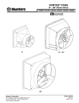
Cool Pad
The cooling table provides settings for the evaporative cool pad system. There are
up to 5 fragments allowing precise control over this system. Several fragments can
be selected for the same day.
Cool Pad
#01
#
From
To
1
2
08:00
10:00
20:00
18:00
Diff
%RH
3.0
5.0
On
85
75
Off
30
60
90
60
FROM: (HH:MM) Start time.
TO: (HH:MM) End time.
DIFF: Differentiation from target temperature to activate cooling. When temperature
raises diff above target, cooling process will begin. When temperature reduces
back to target, cooling process will stop.
%RH: As long as the humidity + Band are below this level the cooling operates.
Cooling stops only at humidity level + band. (See figure below)
ON/OFF: (sec) On/Off cycle by seconds.
Band: The cooling table has its own ‘happy zone’ for temperature and humidity that
can be set at the system parameters under cooling section. The cooling system
turns on the amount above specified in the column ‘Diff’ and turns off when the
temperature drops the amount specified in the band.
+
+
Temp
-
Activate
(Diff)
Band
Stop
HC/MIT/UmGB-1557-05/09
© Munters Europe AB, 2009
Temp.
Stop
Band
RH%
-
Activate
Farm Master & Farm Center User & Installation manual for pigs
Munters reserves the right to make alterations to specifications, quantities, etc. for production or other reasons, subsequent to publication.
34(61)
Farm Master & Farm Center
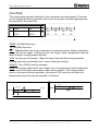
Foggers
The Foggers' table provides settings for the fogger system. There are up to 5
fragments allowing precise control over this system. Several fragments can be
selected for the same day.
Foggers
#01
#
From
To
1
2
08:00
10:00
20:00
18:00
Diff
3.0
5.0
%RH
85
75
On
Off
30
60
90
60
FROM: (HH:MM) Start time.
TO: (HH:MM) End time.
DIFF: Differentiation from target temperature to activate foggers. When temperature
raises diff above target, fogger's process will begin. When temperature reduces
back to target, fogger's process will stop.
%RH: As long as the humidity + Band are below this level the foggers operates.
Foggers stop only at humidity level + band. (See figure below)
ON/OFF: (sec) On/Off cycle by seconds.
HC/MIT/UmGB-1557-05/09
© Munters Europe AB, 2009
Farm Master & Farm Center User & Installation manual for pigs
Munters reserves the right to make alterations to specifications, quantities, etc. for production or other reasons, subsequent to publication.
35(61)
Farm Master & Farm Center
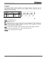
Light
LIGHT
#
Day
1
2
1
5
From
To
14:001
0:00
12:00
16:00
Set the on/off times according to growth day, there are up to five programmable
lines.
Feed
FEED
#
Day
From
To
1
2
5
10
10:00
14:00
12:00
16:00
Set from what hour to what hour you want the feeding to take place, there are up to
five programmable lines.
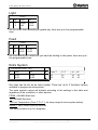
Extra System
EXTRA SYSTEM
#01
#
From
To
From T.
To T.
on
off
1
2
10:00
14:00
12:00
16:00
15
15
40
50
20
30
50
60
Any relay can be set as an extra system. There are up to 3 functions (relays)
available to program as extra system.
The extra system’s relays will activate according to the settings in this table and
regardless of the conditions, or other devices.
FROM: (HH:MM) Start time.
TO: (HH:MM) End time.
To/From Temperature (From T./To T.): the temp range for extra system activity.
ON/OFF: (sec) On/off cycle by seconds.
This table consists of up to 5 programs.
HC/MIT/UmGB-1557-05/09
© Munters Europe AB, 2009
Farm Master & Farm Center User & Installation manual for pigs
Munters reserves the right to make alterations to specifications, quantities, etc. for production or other reasons, subsequent to publication.
36(61)
Farm Master & Farm Center
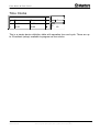
Time Clocks
TIME CLOCKS
#01
#
From
To
on
off
1
2
10:00
14:00
12:00
16:00
20
30
50
60
This is a simple device definition table with operation time and cycle. There are up
to 5 functions (relays) available to program as time clocks.
HC/MIT/UmGB-1557-05/09
© Munters Europe AB, 2009
Farm Master & Farm Center User & Installation manual for pigs
Munters reserves the right to make alterations to specifications, quantities, etc. for production or other reasons, subsequent to publication.
37(61)
Farm Master & Farm Center
Variable Heat
VARIABLE HEAT
Ht Diff
Band
Min(%)
Max(%)
End Day
#01
Heat1
0.0
10.0
Heat2
0.0
10.0
30
100
0
30
100
0
Heat Diff: Differential from heat temperature to initiate variable heaters.
Default: 0.0
Band: Temperature range in witch the variable heater operates in the power
range between minimum and 100%. For example: the heater temperature is
26°C, the temp diff is -1 and the temp band is 2. At 25°C the heater will operate at
minimum power according to minimum heat. At 24°C and down the heater will
operate at 100% and between 26°C and 24°C there will be a power band
between minimum and 100%.
Default: 0.0
Minimum Heat: Minimum heaters operation for safety measures. This parameter
refers to both var. heat 1 and var. heat 2.
Default: 30%
Maximum Heat: Maximum heaters operation for safety measures. This
parameter refers to both var. heat 1 and var. heat 2.
Default: 100%
End Day: Set the last growth day for the Variable Heaters operation.
Default: 0
HC/MIT/UmGB-1557-05/09
© Munters Europe AB, 2009
Farm Master & Farm Center User & Installation manual for pigs
Munters reserves the right to make alterations to specifications, quantities, etc. for production or other reasons, subsequent to publication.
38(61)
Farm Master & Farm Center
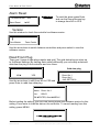
3 MANAGEMENT
Animal Inventory
ANIMAL INVENTORY
#01
Add Mortality
Animal Placed
Animal Update
2
1000
998
This table provides an update for animal inventory.
Add Mortality: insert mortality.
Animals Placed: insert animals placed.
Animal Update: update number of animals.
• In case the wrong figures are accidentally entered, it is possible to correct
them by entering negative figures.
Day & Group
DAY & GROUP
Growth Day
New Group
Group No.
#01
2
Yes/no
4
Day and group keeps monitor the growth of groups
Growth Day: Set the number of growth day. This parameter can also help
determine the animals age.
New Group: To start a new group, select YES under new group fragment and the
controller will automatically increase group number by one and set growth day to 1.
Warning: When starting a new group, history will be deleted!!!
Group No.: You can manually change the group number.
HC/MIT/UmGB-1557-05/09
© Munters Europe AB, 2009
Farm Master & Farm Center User & Installation manual for pigs
Munters reserves the right to make alterations to specifications, quantities, etc. for production or other reasons, subsequent to publication.
39(61)
Farm Master & Farm Center
Alarm setting
Alarm Delay (sec): represents the number of seconds
between failure detection and the alarm operation.
If the problem is solved before the delay time ends,
an alarm will not be recorded in the history log.
==SENSOR ALARM==
Low/High: High and low temperature ranges beyond
which alarm is activated.
==HIGH TEMP==
Out Compensation: This parameter is added to the
high temperature alarm when outside temperatures are
high, like noontime in desert countries. Ensuring you
won't get an alarm just because it's a hot day. The
emergency temperature has no compensation, so the
compensation feature only works when temperatures
do not exceed the emergency temperature.
Example: Outdoor+comp.> Alarm then Alarm =
Outdoor+Comp.
ALARM SETTING
Alarm Delay
► 60
=SENSOR ALARM=
Low Alarm Diff
18.0
Hi. Alarm Diff
18.0
====HIGH TEMP====
Out Compensate
0.0
Emergency Temp
35
=====LOW TEMP=====
Var Fan Stop
NO
======WATER=======
Min Water/hour
0
Max Water/hour
0
=======FEED=======
Min Feed/hour
0
Max Feed/hour
0
===Aux. Alarm===
Aux Relate f()
NONE
For example: IF the pre set compensation is 1°C, the outside temperature is 24°C and
alarm is set to 25°C, the controller adds the outside temperature to the comp, and the
alarm will rise to 26. (25+1=26)
Emerg.
Alarm
Out temp. Compensation.
Comp.
Target
Emergency Temp.: The temperature beyond which the controller goes into emergency
mode and an alarm is activated.
==LOW TEMP==
Variable Speed Stop (Yes/No): When in low temperature alarm, decide whether to
keep variable speed in minimum operation or totally shut down the function.
==WATER & FEED==
Min/Max Water/Hour: A quantity of water per our, above which alarm will activate.
Min/Max Feed/Hour: A quantity of feed per our, above which alarm will activate.
==AUX. ALARM==
• When assigning a related function, alarm occurs if the associated digital input fails to
follow the relay. Digital input must be active when its associated relay is on.
• If there is no related function the alarm will turn on when digital input is active.
HC/MIT/UmGB-1557-05/09
© Munters Europe AB, 2009
Farm Master & Farm Center User & Installation manual for pigs
Munters reserves the right to make alterations to specifications, quantities, etc. for production or other reasons, subsequent to publication.
40(61)
Farm Master & Farm Center
Alarm Reset
ALARM RESET
Alarm Reset
To reset the alarm press Enter
and use the Round Arrows key
to change from NO to YES.
#01
►NO
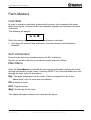
Version
Use this window to check the controller's software version.
CONTROLLER
Farm-Master
Farm-Center
Use the arrow keas to switch between controllers and press select to view the
software version.
Read From Plug
There are 2 types of data plugs regular and gold. The gold data plug can store up
to 8 different settings. By naming each setting differently you can easily write/read
data from the plug to the controller and vice versa.
Read from Plug?
Gold data plug
SELECT SETTING
NO◄
YES
Use the arrow keys to shift from NO to YES and
press Enter to read from data plug.
1.
2.
3.
#1
Room No.1
Room No.2
<NO SETTING>
…8.
DATA ON THE PLUG
Name: Room No. 1
Ver.:
OK
1.00r01
ENTER, Abort
MENU
Before loading the setting, you can view setting name and software version for this
setting. Press enter to load the data on the controller. To cancel reading from this
setting, press MENU.
READING FROM PLUG
PLEASE WAIT
HC/MIT/UmGB-1557-05/09
© Munters Europe AB, 2009
Farm Master & Farm Center User & Installation manual for pigs
Munters reserves the right to make alterations to specifications, quantities, etc. for production or other reasons, subsequent to publication.
41(61)
Farm Master & Farm Center
Write To Plug
Gold data plug
SELECT SETTING
Write to Plug?
NO◄
1.
2.
3.
YES
#1
Room No.1
Room No.2
<NO SETTING>
…8.
Use the arrow keys to shift from NO to YES and press Enter to write over the data
plug.
You can name your current configuration by using the arrow keys.
On the gold data plug, select no setting to create a new setting or overwrite an
existing one.
ENTER SETTING NAME
Name: Room No. 1
To Change ARROWS
OK
ENTER, Abort
MENU
Press enter to load data to the plug.
HC/MIT/UmGB-1557-05/09
© Munters Europe AB, 2009
Farm Master & Farm Center User & Installation manual for pigs
Munters reserves the right to make alterations to specifications, quantities, etc. for production or other reasons, subsequent to publication.
42(61)
Farm Master & Farm Center
4 HISTORY
The history section maintains a memory of activity of the last 100 days and 100
events or alarms.
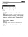
Temperature
TEMPERATURE
#01
DAY
MIN
AVG
MAX
1
24.5
25.8
26.5
2
24.0
25.0
26.5
.
100
Humidity
HUMIDITY
#01
DAY
MIN
AVG.
MAX
1
55.0
60.0
67.0
2
55.0
60.0
66.0
.
100
Sensors: Data collection for minimum, maximum and average in temperature and
humidity for the last 100 days.
Water
WATER
DAY
#01
DAY: Growth day.
DAILY
%
1
0.0
N/A
DAILY: Daily consumption.
2
0.0
N/A
%CHANGE: % Change from previous day.
.
100
HC/MIT/UmGB-1557-05/09
© Munters Europe AB, 2009
Farm Master & Farm Center User & Installation manual for pigs
Munters reserves the right to make alterations to specifications, quantities, etc. for production or other reasons, subsequent to publication.
43(61)
Farm Master & Farm Center
Feed
FEED
DAY
#01
DAILY
%
1
0.0
N/A
2
0.0
3
0.0
N/A
N/A
.
100
DAY: Growth day.
DAILY: Daily consumption.
%CHANGE: % Change from previous day.
Mortality
MORTALITY #01
DAY
DAILY TOTAL
1
0
N/A
2
1
1
.
100
DAY: Growth day.
DAILY: Daily mortality.
TOTAL: Mortality total since growth day one.
Heater
HEATER ROOM #01
DAY
Heat 1
Heat 2
1
01:05
00:00
2
00:42
00:00
.
100
The history heater will show the amount of HH:MM the heater was on that day.
HC/MIT/UmGB-1557-05/09
© Munters Europe AB, 2009
Farm Master & Farm Center User & Installation manual for pigs
Munters reserves the right to make alterations to specifications, quantities, etc. for production or other reasons, subsequent to publication.
44(61)
Farm Master & Farm Center
Alarm
ALARM #01
MESSAGE
TIME
DAY
Press. Fail
18:50
18
High Temp
10:45
14
The following is an example of an Icon status that indicates
activation of alarms.
NOT ACTIVE
AN ALARM THAT WAS RESET
ACTIVE
There are 21 different possible alarm messages:
1.
2.
3.
4.
5.
6.
7.
8.
9.
10.
11.
12.
13.
14.
15.
16.
17.
18.
19.
20.
21.
Ana. In Fail - analog input failure
High Temp - high temperature alarm
Low Temp – low temperature alarm
Hum.Sen Fail- humidity sensor failure
Lost Comm- lost communication
W. Overflow- water over flow
F. Overflow- feed over flow
Sn. 1 Fail – Sensor #1 failure.
Sn. 2 Fail
Sn. 3 Fail
Sn.1 Def Err- sensor definition error
Sn.2Def Err
Sn.3 Def Err
Sn.1 Out Rng- sensor out of range
Sn.2 Out Rng
Sn.3 Out Rng
Sn. Not Def- sensor not defined
Aux Alarm- auxiliary alarm.
Press. Fail
Low S. Press.
High S. Press.
HC/MIT/UmGB-1557-05/09
© Munters Europe AB, 2009
Farm Master & Farm Center User & Installation manual for pigs
Munters reserves the right to make alterations to specifications, quantities, etc. for production or other reasons, subsequent to publication.
45(61)
Farm Master & Farm Center
Event
EVENTS ROOM #1
EVENT
DAY
TIME
1
Menu #11
2
18:53
2
Power up
4
14:42
Besides the menu # event message there
are three kinds of events:
1. Power up- how many times the
controller was turned on.
2. Reset- how many times the controller
was reset.
3. Cold- how many cold starts were
performed.
4. Menu# - which menu number has
been changed.
The events table is similar to the alarms table but without icons. For example: In the
table above “menu #11” means that there was a change of settings in CONTROL
menu 1, Temp Curve table.
HC/MIT/UmGB-1557-05/09
© Munters Europe AB, 2009
Farm Master & Farm Center User & Installation manual for pigs
Munters reserves the right to make alterations to specifications, quantities, etc. for production or other reasons, subsequent to publication.
46(61)
Farm Master & Farm Center
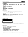
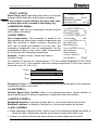
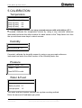
5 CALIBRATION
Temperature
TEMP. CALIB.
#01
Temp-1(Factor)►
Temp-2(Factor)
Temp-3(Factor)
Temp-4(Factor)
0.0
0.0
0.0
n/a
• The temperature sensor is a very accurate sensor with a deviation of 0.1.
If needed, calibrate the temperature sensor by using a very accurate reference
instrument and enter the offset number for each sensor in the Temp factor line. Use
the up and down arrow keys to select sensors.
Humidity
HUM. CALIB.
#01
Humid.(factor)► 0.0
If needed, calibrate the humidity sensor by using a very accurate reference
instrument and enter the offset number in the Humidity factor line.
Pressure
PRESS. CALIB.
Value
#01
A/D
Press ENTER to calib
Water & Feed
Water/feed
#01
Water per pulse 0.1
Feed per pulse
1.0
The water and feed system operates on a pulse counting method.
Enter the amount of feed/water per pulse.
HC/MIT/UmGB-1557-05/09
© Munters Europe AB, 2009
Farm Master & Farm Center User & Installation manual for pigs
Munters reserves the right to make alterations to specifications, quantities, etc. for production or other reasons, subsequent to publication.
47(61)
Farm Master & Farm Center
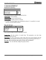
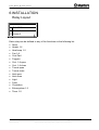
6 INSTALLATION
Relay Layout
RELAY LAYOUT #01
#
FUNCTION
01 Heater 1
02 Heater 2
Each relay can be defined to any of the functions on the following list:
•
•
•
•
•
•
•
•
•
•
•
•
•
•
•
•
•
None
Heater 1-2
Heat lamp 1-2
Fan 1-8
Cool Pad
Foggers
Curt. 1-4 open
Curt. 1-4 close
Tunnel open
Tunnel close
Inlet open
Inlet close
Light
Feed
Circulation
Extra system 1-3
Timer 1-5
HC/MIT/UmGB-1557-05/09
© Munters Europe AB, 2009
Farm Master & Farm Center User & Installation manual for pigs
Munters reserves the right to make alterations to specifications, quantities, etc. for production or other reasons, subsequent to publication.
48(61)
Farm Master & Farm Center
Sensors Layout
ANALOG INPUT #01
OPTIONS
Temp-1
IN
IN / NONE
Temp-2
NONE
IN / NONE
Temp-3
NONE
IN / NONE
Temp-4
OUT
NO / YES/OUT
Humidity
YES
NO / YES
The Sensor Layout accommodates up to- 4 temperature sensors and one humidity
sensor. 3 can be defined for use inside the house and up to one can be used out of
the house. Just mark "IN" for a temperature sensor connected in the house and
OUT for a temp. sensor outside of the house.
Note: only sensor number 4 can be 'Out'.
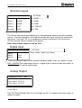
Digital Input
DIGITAL INPUT
Input-1
Input-2
Input-3
#01
Water
OPTIONS
None / Water / Feed / Aux. Alarm
Feed
None
There are 3 digital inputs and a selection between water, feed, aux. alarm or none.
AUX. ALARM: Once operating function, a digital input is sent to make sure that it is
actually on, and if not the alarm starts.
Analog Output
ANALOG OUTPUT #01
# FUNCTION 0% 100%
1 Var. Heat 1 0.0 10.0
2 Var. Heat 2 0.0 10.0
3 Var. Fan 3
4 Var. Fan 4
Use the Round Arrows key to run through the list of outputs and press enter to
select an output.
HC/MIT/UmGB-1557-05/09
© Munters Europe AB, 2009
Farm Master & Farm Center User & Installation manual for pigs
Munters reserves the right to make alterations to specifications, quantities, etc. for production or other reasons, subsequent to publication.
49(61)
Farm Master & Farm Center
Variable Speed Fan
VAR. SPEED FAN
FUNCTION
#01
1 VAR. Fan 1 ► YES
2 VAR. Fan 2 YES
To define a speed fan select yes.
This table will fill out according to the number of triacs in your system (0-2).
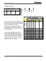
Sensor Definition
FUNCTION
1 2 3 4
Average
+ - + -
Tunnel
+ - - -
Heater 1
+ - - -
Heater 2
- + - +
Heat Lamp 1
- + - -
Heat Lamp 2
- - - +
Curtain 1
+ + - -
Cool cell
- - - -
Ex. System 1 - - - Tun. Curt
- - - +
Var. Heat 1
- - + -
Select the temperature sensors 1-4 to use for
each function using the Round Arrows key to
apply and remove check marks.
You will see only the devices defined in the
relay layout and variable heat.
Average- the average definition refers
to the average temperature, according
to the sensor defined. An empty line
defined for a certain sensor, indicates
that the sensor will operate according
to the average temperature definition.
Curtain Setup
CURTAIN SETUP #01
CURTAIN OPEN CLS
Curtain1►
60
60
Curtain2
60
60
Curtain3
60
60
Curtain4
60
60
Tunnel
60
60
Inlet
60
60
HC/MIT/UmGB-1557-05/09
© Munters Europe AB, 2009
Curtain Setup tells the controller how fast your curtains
and side inlets move. It needs this information to
properly calculate automatic inlet advance as well as
inlet and curtain positions.
Farm Master & Farm Center User & Installation manual for pigs
Munters reserves the right to make alterations to specifications, quantities, etc. for production or other reasons, subsequent to publication.
50(61)
Farm Master & Farm Center
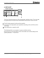
Farm-Masters
Cold Start
In order to execute a cold start, disconnect the power, then reconnect the power
while pressing the 3 buttons of the Farm-Masters together and hold them for about
3 seconds.
The following will appear:
CLd
When this screen appears the controller preformed a cold start.
• Cold start will erase all data and history from the memory and load factory
defaults!!!
Set Unit Number
Press the two arrow key simultaneously until NO. is blinking.
Set the unit number with the up and down arrows and press Select.
Main Menu
Once the Farm-Master is activated the main screen will appear showing the inside
average temperature of the rooms. Pressing SELECT for 2 seconds allows the user
through the main screen’s information.
trg: The target temperature for the room. (Can be changed from the FarmMaster itself, only if a curve was not defined.)
rH: Humidity in room.
rH.t: Target humidity.
day: Growth day for the room.
The display alternates between the name and the figure.
HC/MIT/UmGB-1557-05/09
© Munters Europe AB, 2009
Farm Master & Farm Center User & Installation manual for pigs
Munters reserves the right to make alterations to specifications, quantities, etc. for production or other reasons, subsequent to publication.
51(61)
Farm Master & Farm Center
Calibration
Temperature sensors are very accurate and most likely will not require calibration.
However, if calibration is required it will be done in the following way:
Temperature sensor calibration
¾
¾
¾
¾
Use an accurate thermometer reference.
Place it near the temperature sensor.
Make sure that the inside temperature is stable.
Calibrate the temperature sensor immediately after reading.
Calibration procedure
1. In order to get to the calibration menu press “select” and the “up” arrow
keys simultaneously and hold them together for about two seconds.
2. The display alternates between the sensor number and the temperature
measured.
3. Use the arrow key to change the temperature.
4. Press select to move through the sensors and the arrows to change
temperatures.
NOTE: Calibration of humidity sensor is done exactly the same way; the only
difference is that instead of measuring temperature, the humidity is measured by an
external humidity sensor.
Test
The test option is used mostly in the installation process and it enables the installer
to check systems.
In order to get to test menu, press “select” and “down” arrow keys simultaneously
and hold them together for about two seconds.
The display alternates between the name of the I/O and an ON/OFF sign.
Pressing the arrow keys allows switching between on and off.
rL.1-7: Relays 1 to 7.
SPd: Variable speed.
(Check minimum to full capacity using the arrow keys)
AO1-4: Analog outputs 1 to 4.
t1, t2: Temperature sensors with the A/D counts blinking on the screen.
Hu: humidity sensor A/D counts.
Ai1-2: Analog inputs 1 to 2.
Prs: Pressure A/D counts.
DG1-3: Digital inputs 1 to 3.
HC/MIT/UmGB-1557-05/09
© Munters Europe AB, 2009
Farm Master & Farm Center User & Installation manual for pigs
Munters reserves the right to make alterations to specifications, quantities, etc. for production or other reasons, subsequent to publication.
52(61)
Farm Master & Farm Center
Technical Specifications
Power supply
Mains voltage
single phase
115/230VAC
Main fuse
315 mA
Secondary fuse
1A
Maximum power consumption
10VA
Available power for peripheral equipment
Analog Inputs
3 temperature sensors
RTS-2 (THERMISTOR)
5 analog outputs
20MA
0-:-10V
1 humidity sensor input
0-:-3V
2 analog inputs
0-:-5V
Digital inputs
3 digital inputs
dry contact
5V/2mAmp
Relays outputs
8 N.O. power relays
2HP
30Amps
250Vac
Housing
Dimensions (LxWxH)
92.5x73x36
Ambient climate
Operating temperature range
0ºC to + 50ºC
Storage temperature range
-10ºC to + 70º
Indoor Applications
The equipment is designed for use in Indoor Applications only!
HC/MIT/UmGB-1557-05/09
© Munters Europe AB, 2009
Farm Master & Farm Center User & Installation manual for pigs
Munters reserves the right to make alterations to specifications, quantities, etc. for production or other reasons, subsequent to publication.
53(61)
Farm Master & Farm Center
Farm-Master Installation Guide.
Sensors and Shielded Wiring
1. For long shielded wires, connect the shield to ground at one end only.
2. From the ground terminal, run a heavy wire directly to the ground rod. It is
acceptable, if necessary, to run the heavy ground wire to the electrical service
grounding system rather than directly to the ground rod.
3. Do not use light wires for these ground connections. They must carry heavy
lightning currents, sometimes exceeding thousands of amperes. Certainly, do
not use the shielding of sensor and low voltage wiring for this purpose.
4. Ensure that all ground connections go to a single local point. When lightning
strikes, grounds a meter or two apart will be at significantly different voltages. If
you have several electronic boxes with individual grounds, connect all these
together to a single point (If Possible), preferably to the surge protector ground.
This should continue to the ground rod or the electrical service. In particular,
avoid grounding any controls remotely through shield wiring.
5. Do not use shields to create a path for lightning. For long shield wires, such as
building to building runs, connect the shield to ground at one end only, to
reduce the chance of conducting lightning from one building to another.
6. When splicing sensors to longer wires, ensure that the splice is waterproof.
Use adhesive lined heat shrink (marine grade) to make waterproof connections.
7. Use a good compression connector for splicing. This is better than soldering.
Do not simply twist wires together and then cover with electrical tape.
8. Keep sensor wiring separate from other power distribution and high voltage
wiring. Ensure that lightning on other wiring will not transfer to the sensors.
9. Install outside temperature sensors so that the sun will not cause false
readings, and so that exhaust air from the building will not affect the sensor.
HC/MIT/UmGB-1557-05/09
© Munters Europe AB, 2009
Farm Master & Farm Center User & Installation manual for pigs
Munters reserves the right to make alterations to specifications, quantities, etc. for production or other reasons, subsequent to publication.
54(61)
Farm Master & Farm Center
Installation and Electrical Connections
1. Install computerized electronic controls at least one meter (three feet) away
from interference sources such as high voltage wiring to motors, variable
speed, light dimmers, relays.
2. Install electronic controls in a separate ventilated control room that is
protected from extreme temperatures and dirty environments. Place the
controls so that the operators can conveniently use the control and read
indicators and displays.
3. Give your installation a professional appearance, with all wiring in conduit or
neatly installed. Keep low voltage wires separate from high voltage wires.
4. Use shielded wiring for low level signals. For buried wiring (building to
building runs) use high grade jell filled cables that are impervious to
moisture.
5. Seal cable entry points and control boxes to prevent contamination and
corrosion. If you use silicon sealant with acetic acid cure, keep the control
open and ventilated until cured. Otherwise, the acetic acid will attack the
metal parts, including circuitry.
6. Drill cable entry holes on the bottom of the box only.
HC/MIT/UmGB-1557-05/09
© Munters Europe AB, 2009
Farm Master & Farm Center User & Installation manual for pigs
Munters reserves the right to make alterations to specifications, quantities, etc. for production or other reasons, subsequent to publication.
55(61)
Farm Master & Farm Center
Mechanical Installation Guide
The Farm-Master must be installed by an authorized electrician. Power
must be disconnected to avoid electrical shock and damage.
To avoid exposing the Farm-Master to harmful gases or high humidity, it
is recommended to install it in the service room.
Installation Category (Over voltage Category) II
The power supply to the controller should be protected by 10
Amps circuit breaker
All electrical connections should comply with National
Electrical code (NEC)
1. Open the enclosure lid by unfastening the four screws.
2. Using the provided bag of screws and plastic caps, drill holes in the three
designated areas inside the Farm-Master. Place caps on the screws once
mounting is complete.
3. Drill holes at bottom of the box and place cable holders.
4. Place the required cables through the cable holders at the bottom of the unit.
Connect the wires according to the wiring diagrams.
5. Make sure that you use wires large enough for the load of the variable
speed.
6. To connect temperature and humidity sensors use shielded two or four
conductor #18-#24 gauge cables. Connect the shields to the Ground metal
strip. Do not connect the shields to more than one point, or you may induce
ground loop currents.
7. Close the Farm-Master enclosure lid carefully and tightly. Use RTV silicon or
equivalent sealant to seal the cable holders.
8. After installation is completed, operate the Farm-Master for a few hours and
re- check for proper operation.
Environmental Protection
Recycle raw materials instead of disposing as waste. The controller,
accessories and packaging should be sorted for environmentalfriendly recycling. The plastic components are labeled for categorized
recycling.
HC/MIT/UmGB-1557-05/09
© Munters Europe AB, 2009
Farm Master & Farm Center User & Installation manual for pigs
Munters reserves the right to make alterations to specifications, quantities, etc. for production or other reasons, subsequent to publication.
56(61)
Farm Master & Farm Center
Metal Sheet Assembly Diagram
Plastic Caps
Screws
Figure 1: Metal sheet assembly diagram
Instructions
1. Drill holes in the three designated areas located in the back of the controller.
2. Mount the controller using the 3 screws provided in the small plastic bag.
3. Place the provided plastic caps on the screws.
HC/MIT/UmGB-1557-05/09
© Munters Europe AB, 2009
Farm Master & Farm Center User & Installation manual for pigs
Munters reserves the right to make alterations to specifications, quantities, etc. for production or other reasons, subsequent to publication.
57(61)
Farm Master & Farm Center
Farm-Center/Farm-Master Network Connection
To P.C com
HC/MIT/UmGB-1557-05/09
© Munters Europe AB, 2009
Farm Master & Farm Center User & Installation manual for pigs
Munters reserves the right to make alterations to specifications, quantities, etc. for production or other reasons, subsequent to publication.
58(61)
Farm Master & Farm Center
Farm Master Wiring Diagram 1
(Analog Output, Power, Potentiometer, Relays, Variable speed, RHS-2)
HC/MIT/UmGB-1557-05/09
© Munters Europe AB, 2009
Farm Master & Farm Center User & Installation manual for pigs
Munters reserves the right to make alterations to specifications, quantities, etc. for production or other reasons, subsequent to publication.
59(61)
Farm Master & Farm Center
Communication Wiring Diagram
HC/MIT/UmGB-1557-05/09
© Munters Europe AB, 2009
Farm Master & Farm Center User & Installation manual for pigs
Munters reserves the right to make alterations to specifications, quantities, etc. for production or other reasons, subsequent to publication.
60(61)
Munters Europe AB, HumiCool Division, Kung Hans Väg 8, P.O. Box 434, SE-191 24 Sollentuna, Sweden.
Phone +46 (0)8-626 63 00, Fax +46 (0)8-754 56 66.
Munters Italy S.p.A., Strada Piani 2, IT-18027 Chiusavecchia, Italy. Phone +39 0183-52 11, Fax +39 0183-521 333.
www.munters.com
Austria via sales organization in Germany, Munters Euroform GmbH, Phone +49 (0)241-89 000, Fax +49 (0)241-89 005 189, Denmark via sales organization in Sweden, Munters Europe AB,
Phone +46 (0)8-626 63 00, Fax +46 (0)8-754 56 66, Finland Munters Oy, Phone +358 (0)9-83 86 0330, Fax +358 (0)9-83 86 0336, France Munters France S.A., Phone +33 (0)1-34
11 57 50, Fax +33 (0)1-34 11 57 51, Germany Munters Euroform GmbH, Phone +49 (0)241-89 000, Fax +49 (0)241-89 005 189, Italy Munters Euroemme S.p.A., Phone +39 018352 11, Fax +39 0183-521 333, Kingdom of Saudi Arabia and Middle East Hawa Munters, c/o Hawa United Cooling Syst. Co. Ltd., Phone +966 (0)1-477 15 14, Fax +966 (0)1-476
09 36, Norway via sales organization in Sweden, Munters Europe AB, Phone +46 (0)8-626 63 00, Fax +46 (0)8-754 56 66, South Africa & Sub-Sahara Countries Munters (Pty) Ltd,
Phone +27 (0)11-971 9700, Fax +27 (0)11-971 9701, Spain Munters Spain S.A., Phone +34 91-640 09 02, Fax +34 91-640 11 32, Sweden Munters Europe AB, Phone +46 (0)8-626
63 00, Fax +46 (0)8-754 56 66, Switzerland via sales organization in Germany, Munters Euroform GmbH, Phone +49 (0)241-89 000, Fax +49 (0)241-89 005 189, United Kingdom
Munters Ltd, Phone +44 (0)845-644 3980, Fax +44 (0)845-644 3981, Export & Other countries Munters Europe AB Phone +46 (0)8-626 63 00, Fax +46 (0)8-754 56 66, Region
Americas Munters Corporation, Phone +1 (0)978-241 1100, Fax +1 (0)978-241 1219, Region Asia Munters K.K., Phone +81 (0)3-5970 0021, Fax +81 (0)3-5970 3197.
®Euroemme is a registered trademark of Munters AB.