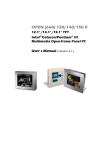
1
CHAPTER 3
System Installation
This chapter provides you with instructions on how to set up your computer system using
PPB-600 Panel Computer Board. The additional information shows you how to install Msystems Flash disk, set up LCD display, Ethernet and handle WDT operation in software
program.
3-1 Socket 370 Processor
Installing CPU
1) Lift the handling lever of CPU socket outwards and upwards to the other end.
2) Align the processor pins with pinhole on the socket. Make sure that the notched corner or
dot mark (pin 1) of the processor is latched by the socket’s lever end. Press the CPU down
gently until it fits into the place. If this operation is not easy or smooth, don’t do it with
force. You need to check and rebuild the CPU pin evenly.
3) Push down the lever to lock processor chip into the socket.
4) Follow the installation guide of cooling fan or heat sink, and mount it on CPU surface and
lock it on the socket 370.
5) Be sure to follow particular CPU speed and voltage type to adjust the jumper settings
properly. (For S370 processors available in the market, there is no need to care about this
since these processors are all locked on core/bus ratio inside. Only engineering sample
processors are on the edge of this care)
Removing CPU
1) Unlock the cooling fan first.
2) Lift up the lever of CPU socket outwards and upwards.
3) Carefully lift up the processor and remove it from the socket.
4) Follow the steps of installing a CPU to change to another processor, or place the handling
bar down to close the opened socket.
3-2 Main Memory
This PPB-600 provides one 168-pin Dual In-line Memory Module (DIMM) to support onboard main memory. The maximum memory size for 3.3V EDO DRAM or SDRAM is 256MB.
Normally, the DIMM used could be either 3.3V EDO (Extended Data Out) memory with
speed less than 70ns or 3.3V SDRAM (Synchronized DRAM) with speed less than 100ns (-10).
If you adopt 100MHz system clock, you need to use SDRAM with speed less than 80ns (-8). It
is better to use PC100-compliant memory chip on your system.
For system compatibility and stability, don’t use memory module without brand. You can
also use the single or double-side DIMM without parity check and ECC function.
Watch out the contact and lock integrity of memory module with socket, it will impact on the
system reliability. Follow normal procedure to install your DRAM module into memory
socket. Before locking, make sure that the module has been fully inserted into card slot.
NOTE: For maintaining system stability, don’t change any of DRAMS parameters in BIOS
setup to upgrade your system performance except for getting technical
information.
PPB-600 User’s Manual 3-3 M-systems Flash Disk
PPB-600 reserves one 32-pin DIP sockets for installing M-systems Flash disk from 2MB to
288MB. This operation structure is running with pure ISA-bus without PnP (Plug and Play)
function. Before installing, make certain that I/O address jumper setting is set on right
position to prevent unworkable system due to I/O resource conflict. Do remember to follow
DOC (Disk-On-Chip) installation procedure. Otherwise, the Flash chip is possible to be
burned out due to incorrect installation.
Installation: Align the DOC with pinhole on the socket. Make sure that the notched corner or
dot mark (pin 1) of DOC is latched on the notched corner of the socket. Press the DOC gently
down until it fits into the place. If installation procedure is correct, the Flash disk can be
viewed as a normal hard disk with direct access read/write on data.
WARNING: Please ensure that your DOC is properly inserted. Placing the DOC in reverse
way will cause severe damage.
If you want to boot from this Flash disk, it is necessary to refer to the application note from Msystems. You can easily obtain relative information from M-systems shipping package (such
as product manual) or M-systems website http://www.m-sys.com
3-4 Installing the Single Board Computer
To install your PPB-600 into standard chassis or proprietary environment, you need to go
through the following:
Step 1: Check all jumper settings on proper positions
Step 2: Install and configure CPU and memory module on right position
Step 3: Place PPB-600 into the dedicated position in your system and secure it with screws
Step 4: Attach cables to existing peripheral devices and secure them
NOTE: Please refer section 3-4-1 to 3-4-3 to install device driver for VGA, LAN, and Sound
to setup your system.
3-4-1 CHIPS 69000 Graphics Controller
The on-board graphics controller adopts CHIPS 69000 that integrates high performance
memory technology for the graphics frame buffer. Based on the proven HiQ Video graphics
accelerator cores, the 69K chipset combines state-of-the-art flat panel controller capabilities
with low power, high performance integrated memory. It incorporates 2MB of proprietary
integrated SDRAM for the graphics/video frame buffer. The integrated SDRAM memory can
support up to 83MHz operation, thus increasing the available memory bandwidth for the
graphics subsystem to support high color/high resolution application.
The 69000 chipset supports a wide variety of monochrome and color Single-Panel, SingleDrive and Dual-Panel, Dual Drive, standard and high-resolution, passive STN and active
matrix TFT/MIM LCD, and EL panels. It is designed to support high performance graphics
and video acceleration for all supported display resolutions, display types, and colors modes.
This PCI device 69000 can be configured to operate an analog CRT monitor and flat panel at
the same time.
PPB-600 User’s Manual Display Modes Supported
The 69000 support the modes in the following table.
Resolution
Color (bpp)
Refresh Rates (Hz)
640x480
8
60, 75, 85
640x480
16
60, 75, 85
640x480
24
60, 75, 85
800x600
8
60, 75, 85
800x600
16
60, 75, 85
800x600
24
60, 75, 85
1024x768
8
60, 75, 85
1024x768
16
60, 75, 85
1280x1024
8
60
PPB-600 utilizes on-board CHIPS 69000 and optional panel display module to support 16
types of panels. You can select one of sixteen LCD panel types by BIOS panel setting in
“Advanced CMOS Setup”. The following table shows you how to correctly configure those
BIOS options in Advanced CMOS Setup in order to fetch an acceptable display on either CRT
or LCD.
LCD CRT Selection
Display on CRT
Display on LCD
LCD Type
CRT Only
YES
NO
Do not care
LCD Only
NO
YES
Type 1 to 16
Simultaneous
YES
YES
Type 1 to 16
Notice:
1.
2.
If you have CRT as the display, please select “CRT Only” or “Simultaneous”.
1.1 Selecting “CRT only” will disable LCD display and provide correct display resolution
on CRT.
1.2 You do not have to care about “LCD type” since there is no LCD display.
1.3 Selecting “Simultaneous” will provide correct display both on CRT and LCD.
However, the display resolution will be affected by the limitation of LCD size. If your
LCD only support “640 x 480”, there is no way to configure a higher resolution and
you will have only “640 x 480” as the optimally available resolution on both CRT and
LCD. Please refer to the next notice for the correct “LCD Type” selection.
If you have LCD as the display, please select “LCD only” or “Simultaneous”.
2.1 Selecting “LCD Only” will disable CRT display and provide correct display
resolution on LCD.
2.2 You will have to select a correct “LCD type”. Otherwise your display on LCD will be
corrupted or lost while CRT is still able to give you a correct resolution.
2.3 PPB-600 BIOS uses “Type 8” as the default “LCD type” setting, and you will have to
change the “LCD type” after you load in the optimal BIOS setting, if your LCD is not
“Type 8”.
2.4 In the event that LCD display is lost or corrupted, please use CRT as the monitoring
display for a diagnostic process since it will not be affected by the change of “LCD
Type” setting.
2.5 You can also select “Simultaneous” with LCD as the display.
PPB-600 User’s Manual Driver Support
PPB-600 provides one CD-Title to support on-board VGA device drivers in various operating
systems. This CD-Title only includes one directory \vga69000. Before installing the device
driver, please see the reference files in each sub-directory. If you have problems to install
drivers directly from CDROM, please copy the files into your hard drive before you
proceed with the driver installation.
!"VGA: This driver supports Windows-NT 3.5/4.0, Windows-95/98/98SE/ME/2000, SCO
OpenServer V5.0.2 or above, and SCO Unixware V7.11 or above.
Notice
1.
For a successful installation of VGA driver in Windows-NT 3.51 environment, you should
build a diskette with the VGA drivers to support valid data path “Disk1”. Please prepare
one diskette and create a directory \disk1 under its root. Copy all files under
\vga69000\NT_35 from the CD-Title into \disk1. When the computer asks you for VGA
drivers during the installation of NT3.51, the VGA drivers are all located in the diskette.
2.
Our C&T 69000 video chipset supports the following Non-MicroSoft operating systems.
The associated drivers are embedded in the operating systems already.
a.
b.
c.
d.
e.
f.
g.
h.
3.
QNX V4.25
Redhat Linux V6.0 (Kernel 2.2.14) or above
Maindrake Linux 6.1 (Kernel 2.2.11) or above
SuSE Linux V7.0 (Kernel: 2.2.16)
OpenLinux V2.4 (Kernel 2.2.14)
Turbo Linux V6.0.4 (Kernel: 2.2.14)
Slackware Linux V7.1.0 (Kernel: 2.2.16)
FreeBSD V4.0
There is no C&T 69000 video driver for Solaris 8 (Intel Version). However, user is still able
to use this operating system.
3-4-2 Sound ESS1938S (solo-1) Controller
The Solo-1 PCI Audio Driver solution implements a single-chip PCI audio solution, providing
high-quality audio processing while maintaining full legacy DOS game compatibility. With a
dynamic range 80dB, the Solo-1 complies with Microsoft PC 97 / PC 98 specifications and
meets WHQL audio requirements.
Driver Support
PPB-600 provides one CD-Title to support on-board sound device drivers in various
operating systems. This CD-Title only includes one directory \sound1938. Before installing
the device driver, please see the reference files in each sub-directory.
PPB-600 User’s Manual !" Sound: This driver supports Windows-NT 3.5/4.0, Windows-95/98/98SE/ME/2000.
3-4-3 Intel 82559 Fast Ethernet Controller
The 82559 is Intel’s second-generation fully integrated 10BASE-T / 100BASE-TX LAN
solution. The 82559 consists of both the Media Access Control (MAC) and the physical layer
(PHY) interface combined into a single component solution.
Driver Support
PPB-600 provides one CD-Title to support on-board sound device drivers in various
operating systems. This CD-Title only includes one directory \Ethernet. Before installing the
device driver, please see the reference files in each sub-directory.
!" Ethernet: This driver supports Windows-NT 3.5/4.0, Windows-95/98/98SE/ME/2000.
3-5 Watch Dog Timer Programming
There are two manners to activate the Watch-Dog Timer (WDT) function. One is to utilize
hardware jumper setting and programmed by software command. After this feature is
enabled, a system reset will be generated unless an application triggers the timer periodically
within time-out period. This allows the system to restart in an orderly way in case of any
abnormal condition is found. Another one is to program super I/O W83977ATF chip to start
WDT time-out counting. It is recommended to use first approach. The second choice is
comparatively difficult and complicated. In addition, you can also connect WDT output to
NMI input by setting JP3 jumper to generate NMI event to support special interrupt service
routine.
An optional two-port WDT is provided on PPB-600. This WDT comes with 8 possible ranges
of time intervals from 500 ms to 64 sec., which can be adjusted by setting jumper positions. It
could be enabled and programmed by reading I/O port 0533H or 0543H to issue trigger
continuously, and disabled by reading I/O port 0033H or 0343H. A tolerance of 30% timer
limit must be considered. For instance, if the time-out interval is set to 1second, the WDT
trigger command must be issued within 700ms at least.
The below example gives you a reference algorithm for WDT programming via I/O port
0533H and 0033H in your application program:
Enable WDT
MOV
IN
DX, 0533H
AL, DX
MOV
IN
DX, 0533H
AL, DX
MOV
IN
DX, 0033H
AL, DX
Re-trigger WDT
Disable WDT
PPB-600 User’s Manual Notice:
1.
2.
There is one demo program for DOS or Windows environment (Windows-95/98). Users
may use this demo program to feel the operation of WDT.
Using WDT in Non-DOS-based operating systems, such as Windows-NT 4.0 or Linux,
requires special drivers. Users may find a programming guide in the CD-title to
customize real applications and driver.
PPB-600 User’s Manual