1
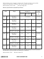
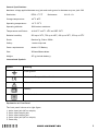
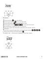
HANDHELD DIGITAL CLAMP
MULTIMETER
AX-C850
OPERATOR’S INSTRUCTION MANUAL
Safety Information
To avoid possible electric shock or personal injury:
• Never apply more than 30V between any two jacks, or between any jack and earth ground.
• Make sure the battery door is closed and latched before you operate the calibrator.
• Remove test leads from the calibrator before you open the battery door.
• Do not operate calibrator if it is damaged.
• Do not operate the calibrator around explosive gas, vapor, or dust.
To avoid possible damage the calibrator:
• Make sure choose the right jack and rang, before use the calibrator to measurement or calibrator.
• Take away the calibrator from the used circumstance, before operate the calibrator or after close
the calibrator.
Introduction
RTD Process Calibrator is exactitude measurement and source instrument, it can be use to calibrate
the RTD* transmitter (include most impulse transmitter).
RTD Process Calibrator can measure or simulate 7 difference types of RTD ( o C or o F) and measure
or simulate the Resistance. But it could not use to measurement or source at a same time.
The accessories: 2 pair of test lead and alligator clip, 6 *AAA 1.5V battery, user’s manual.
If the Calibrator is broken or short of some accessories, please contact the supplier.
The following table has showed the technical parameter and function of the Calibrator.
Specification
All the specification will under 1 year calibration cycle and temperature between 18~28oC,
except addition explain.
Measure (input)/Simulate (output) Resistance specification.
Range
Measure accuracy
Simulate accuracy
Admie excitation
4W ± Ω
±Ω
mA
0,15
0,1 ~ 0,5
0,00 Ω ~400,00 Ω
0,1
0,1
0,5 ~ 3,0
400,0 Ω ~ 1500,0 Ω
0,5
0,5
0,05 ~ 0,8
1
0,05 ~ 0,4
1
1500,0 Ω ~ 3200,0 Ω
*
2
RTD Resistance Temperature Detector
2
Admit excitation current only apply on simulate mode. The admit excitation current could be
marked on the OHM meter or RTD meter which was connected to the calibrator.
Admit excitation current: 0.2mA
Max input voltage: 30V
Measure (input)/Simulate (output)RTD specification
Mode
Accuracy oC
Range
Input 4W
Input 2W/3W
Admie
excitation
Output
mA
Pt10
385
-200~800oC / 328~1472oF
Pt50
385
-200~800oC / 328~1472oF
0,7
1,0
0,7
0,1~3,0
Pt100
385
-200~800oC / 328~1472oF
0,33
0,5
0,33
0,1~3,0
Pt200
385
-200~250oC / 328~482oF
0,2
0,3
0,2
0,1~3,0
250~630oC / 482~1166oF
0,8
1,6
0,8
-200~500oC / 328~932oF
0,3
0,6
0,3
500~630oC / 932~1166oF
0,4
0,9
0,4
-200~100oC / 328~212oF
0,2
0,4
0,2
100~630oC / 212~1166oF
0,2
0,5
0,2
-200~630oC / 328~1166oF
0,3
0,5
0,3
Pt500
Pt1000
Pt100
385
385
JIS
Nie określana
0,1~3,0
0,05~0,8
0,05~0,8
0,1~3,0
Admit excitation current only apply on simulate mode. The admit excitation current be marked on
the OHM meter or RTD meter which was connected to the calibrator.
Admit excitation: 0.2mA
Max input voltage: 30V
3
General Specifications:
Maximum voltage applied between any jack and earth ground or between any tow jack: 30V
RTD 0.1 oC/oF
Resolution:
o
Resistance:
0.01/0.1 Ω
o
Storage temperature:
-40 C~60 C
Operating temperature:
-10 oC~55 oC
Operating altitude:
3000 meters maximum
Temperature coefficient:
±0.01%/oC on 0oC~18oC and 28oC~50oC
Relative humidity:
95% up to 30oC, 75% up to 40oC, 45% up to 50oC, 35% up to 55oC
Shock:
Random 2g, 5Hz to 500Hz
Safety:
1 meter drop test
Power requirements:
6xAAA 1.5V Battery
Size:
205mmx98mmx46mm
Weight:
472 g (include battery)
International Symbols
Symbol
Meaning
Earth ground
Conform to European Union directives
Refer to his instruction sheet for information about this feature
Battery
Double insulation
Explanation on Front Panel
The front panel is show as in right figure:
1. 4wire input jack (NC on output)
2. 2wire input/output jack
3. 2wire input/output jack
4. 3wire input jack (NC on output)
5. Power key
4
6. RTD mode key
7. oC/oF key
8. Input/Output key
9. Increase more value key/wire mode select
10. Reduce more value key/wire mode select
11. Increase less value key
12. Reduce less value key
13. Low power indication
14. Output state indication
15. Output state indication
16. Reading value
17. Unit indication
18. Mode indication
Operation Instructions
RTD measurement
1 Press the power key 5 , turn on the calibrator.
2 Press the Input/Output key 8 , when on the input mode.
3 Press RTD mode key 6 , on the measure type you want.
4 Put the RTD or Resistance on the input jack.
5 If you want to measure with 3W/4W mode, press the wire mode select key 9 , 10
to select,
and put the wire to the correspond input Jack.
6 Get the reading value 16
*The number in the , referring to the „Explanation on Front Panel” (Page 4)
5
RTD Simulate
1 Press the power key 5 , turn on the calibrator
2 Press the input/output key 8 , when on the output mode.
3 Press the RTD mode key 6 , on the measure type you want.
4 Press the adjust value key 9 , 10 , 11 , 12 , to let the value on your need.
5 Put the RTD meter or Resistance meter on the input Jack.
6 If you want to output with 3W/4W mode, put the other wire on the 2wir jack like
the left picture.
7 If you want to change the output value, then press the adjust value key 9 , 10 , 11
or change to other RTD type use the RTD mode key 6 .
,
12 ,
*The number in the , referring to the „Explanation on Front Panel” (Page 4)
6
Maintenance
Cleaning
Periodically wipe the case with a damp cloth and detergent; do not use abrasives or solvents.
Calibration
Calibrate your calibrator once a year to ensure that it performs according to its specifications.
Replacing the Battery
Please change the battery when the LCD indicates
.
Turn off the power of the Calibrator, when you change the battery, and screw off the breechblock
on the battery cabinet cover, then take off it and instead the fresh AAA 1.5.V battery.
7