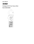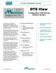
1
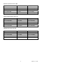
User’s Manual
1200A 3-Phase Power Analyzer/Datalogger
MODEL 382100
Table of Contents
1.0 INTRODUCTION
1-1 Features ................................................................................................ . 3
1-2 Warranty .................................................................................................. 3
1-3 Safety ..................................................................................................... .3
2.0 SPECIFICATIONS
2-1 General Specifications ................................................................................. .5
2-2 Electrical Specifications ....................................................................................5
3.0 METER DESCRIPTION................................................................................ .9
4.0 MEASUREMENT PREPARATION
4-1 The original screen........................................................................................................10
4-2 Entering the measurement Screen..................................................................... 10
4-3 Keypad Description Summary ........................................................................... .10
4-4 SETUP Key....................................................................................................................11
4-5 Meter Setup Functions (SD Card, PT/CT, Audible Beeper, Decimal Point,
Clamp Type, RS-232, Time/Date, Reset Key) .................................................... .12
5.0 MEASUREMENT PROCEDURES
5-1 1Φ 2W (single phase two wires) measurement ......................................... .25
5-2 1Φ 3W (single phase three wires) measurement ...................................... .26
5-3 3Φ 3W (three phase three wires) measurement ....................................... .27
5-4 3Φ 4W (three phase four wires) measurement ......................................... .28
5-5 CT and PT measurement............................................................................................29
5-6 Data Logger ........................................................................................................................30
5-7 Data Hold ....................................................................................................... .31
5-8 Display Backlight key .................................................................................... .32
5-9 A (Current) Range key .................................................................................................33
5-10 LOWBAT (Low Battery) screen ................................................................. .34
5-11 Appendix - Measurement Definitions .............................................................. .35
6.0 MAINTENANCE
6-1 Cleaning ................................................................................................................ .35
6-2 Battery Replacement........................................................................................... .35
7.0 PC INTERFACE
7-1 RS-232 Protocol .............................................................................. .36
7-2 Download Data from SD Card .......................................................... 37
8.0 Customer Support .................................................................................... .40
2
382100 V1.0 7/09
1.0 Introduction
Congratulations on your purchase of the Model 382100 Power Analyzer. This instrument is
fully tested and calibrated prior to delivery; proper use and care of this meter will provide
years of reliable service.
1.1 Features
• Large dot-matrix, numerical, backlit LCD
• Full system analysis with up to 35 parameters:
- V (phase-to-phase), V (phase-to-ground)
- A (phase-to-ground)
- KW / KVA / KVAR / PF (phase)
- KW / KVA / KVAR / PF (system)
- KWH / KVAH / KVARH / PFH (system)
- Phase angle
• High accuracy Auto-ranging current clamps (0.2A to 1200.0A)
• 600.0VAC input with CAT III-600V safety rating
• Adjustable Current Transformer (CT) and Voltage Transformer (VT) ratio for high
power distribution systems
• Log up to 60,000 reading on removable SD memory card in Excel® format
• Wide sampling rate range (from 2 seconds up to 2 hours)
• Captured measurements imported directly into Excel via the SD memory card
• Easy-to-use onscreen menu
• Easy-to-grab rugged over-molded housing
1.2 Warranty
EXTECH INSTRUMENTS CORPORATION (A FLIR COMPANY) warrants this instrument to be free of
defects in parts and workmanship for three years from date of shipment (a six month limited warranty
applies on sensors and cables). If it should become necessary to return the instrument for service during or
beyond the warranty period, contact the Customer Service Department at (781) 890-7440 ext. 210 for
authorization or visit our website at www.extech.com (click on ‘Contact Extech’ and go to ‘Service
Department’ to request an RA number). A Return Authorization (RA) number must be issued before any
product is returned to Extech. The sender is responsible for shipping charges, freight, insurance and proper
packaging to prevent damage in transit. This warranty does not apply to defects resulting from action of the
user such as misuse, improper wiring, operation outside of specification, improper maintenance or repair, or
unauthorized modification. Extech specifically disclaims any implied warranties or merchantability or fitness
for a specific purpose and will not be liable for any direct, indirect, incidental or consequential damages.
Extech's total liability is limited to repair or replacement of the product. The warranty set forth above is
inclusive and no other warranty, whether written or oral, is expressed or implied.
3
382100 V1.0 7/09
1.3 Safety
•
CAUTION: Risk of electric shock. Do not attempt to open or disassemble the meter
while taking measurements
•
CAUTION: Do not attempt to measure Voltage or Current that exceeds specified
limits
•
Remove the test leads from the meter before opening the battery compartment
cover
•
When cleaning, use only a dry cloth to wipe the meter housing. Do not use liquids of
any kind to clean the meter
•
Safety Symbols:
CAUTION
RISK OF ELECTRIC SHOCK
Environmental Conditions
•
Installation Category III 600V
•
Pollution Degree 2
•
Altitude limit: 2000m
•
Indoor use only
•
Relative Humidity maximum: 80%
4
382100 V1.0 7/09
2.0 Specifications
2.1 General Specifications
Circuit
Custom one-chip microprocessor LSI circuit
Display
LCD Size: 3.2 X 2.4” (81.4 X 61 mm)
Dot Matrix backlit LCD (320 X 240 pixels)
Measurements
ACV / ACA / AC Watts (True Power)
AC Watts (Apparent Power)
AC Watts (Reactive Power)
Power factor
Phase angle
Frequency
Wire connections
1P/2W, 1P/3W, 3P/3W, 3P/4W.
Voltage ranges
10 ACV to 600 ACV (Auto Range)
Current ranges
0.2 ACA to 1200 ACA (Auto / Manual Range)
Safety standard
IEC1010 CAT III 600 V
ACV input
impedance
10M ohms
Range select
ACV
Auto Range
ACA
Auto / Manual Range
Clamp frequency
response
40 Hz to 1 KHz
Tested frequency
45 to 65 Hz
Over load
protection
ACV
720 ACV RMS
ACA
1300 ACA with clamp probe
Over-range indicator
"OL"
Under-range indicator
"UR"
Data Hold
Freezes displayed reading
Data Recording
SD memory card
Sampling Time
Approx. 1 second
Datalogger
Real time data logger saves data to SD memory card for
download to PC (data file opens directly to spreadsheet)
Sampling rate: 2 seconds to 7200 seconds
Data Output
Serial or USB connection (cable supplied)
Operating Temp.
0 to 122 F (0 to 50 C)
Operating R.H.
80% Relative Humidity max.
Power Supply
Eight (8) ‘AA’ 1.5VDC batteries or AC - DC 9V power adapter
Power Consumption
Meter: 300 mA DC; Clamp: 20 mA DC
Max. Conductor size
Clamp can accommodate up to 3.4” (86 mm) diameter
o
o
5
382100 V1.0 7/09
Weight
Dimensions
Meter: 2.3 lbs. (1049g) (with batteries); Clamp: 1.2 lbs (522g)
Meter: 8.86 X 4.92 X 2.52“ (225 X 125 X 64 mm)
Clamp: 8.3 X 2.5 X 1.3” (210 X 64 X 33mm)
Clamp Jaw: 3.4” (86 mm)
Accessories Included
Instruction manual
Test Leads: 1 Set (4 pieces)
Alligator clips: 1 Set (4 pieces)
Clamp Probe (3)
AC to DC 9V adapter
SD card (2G)
Carrying case
2.1 Electrical Specifications
ACV
Range
Resolution
Accuracy
10.0V to 600.0V
Phase to neutral line
0.1V
± (0.5%+0.5V)
Range
Resolution
Accuracy
20A
0.001A/0.01A
± (0.5%+0.1A)
200A
0.01A/0.1A
± (0.5%+0.5A)
1200A
0.1A/1A
±(0.5%+5A)
Range
Resolution
Accuracy
0.00 to 1.00
0.01
± 0.04
10.0V to 600.0V
Phase to phase
ACA
Power Factor
PFH (Power Factor Hours): Long Term Power Factor
For three phase/four wire and three phase/three wire configurations:
PF = (PF1 + PF2 + PF3) / 3
For single phase three wire configurations:
PF = (PF1 + PF2) / 2
6
382100 V1.0 7/09
Phase Angle
Range
Resolution
Accuracy
0.1°
± 1°
Range
Resolution
Accuracy
45 to 65 Hz
0.1 Hz
0.1 Hz
-180°
to 180°
Frequency
Active (Real) Power
Range
Resolution
Accuracy
0.000 to 9.999 KW
0.001 KW
± (1%+0.008KW)
10.00 to 99.99 KW
0.01 KW
± (1%+0.08KW)
100.0 to 999.9 KW
0.1 KW
± (1%+0.8KW)
0.000 to 9.999 MW
0.001 MW
± (1%+0.008MW)
Range
Resolution
Accuracy
0.000 to 9.999 KVA
0.001 KVA
± (1%+0.008KVA)
10.00 to 99.99 KVA
0.01 KVA
± (1%+0.08KVA)
100.0 to 999.9 KVA
0.1 KVA
± (1%+0.8KVA)
0.000 to 9.999 MVA
0.001 MVA
± (1%+0.008MVA)
Range
Resolution
Accuracy
0.000 to 9.999 KVAR
0.001 KVAR
± (1%+0.008 KVAR)
10.00 to 99.99 KVAR
0.01 KVAR
± (1%+0.08 KVAR)
100.0 to 999.9 KVAR
0.1 KVAR
± (1%+0.8 KVAR)
0.000 to 9.999 MVAR
0.001 MVAR
± (1%+0.008 MVAR)
Apparent Power
Reactive Power
7
382100 V1.0 7/09
Watt Hour (Active Power Hour): WH
Range
Resolution
Accuracy
0.000 to 9.999 KWH
0.001 KWH
± (2%+0.008 KWH)
10.00 to 99.99 KWH
0.01 KWH
± (2%+0.08 KWH)
100.0 to 999.9 KWH
0.1 KWH
± (2%+0.8 KWH)
0.000 to 9.999 MWHR
0.001 MWH
± (2%+0.008 MWH)
VA Hour (Apparent Power Hour): SH
Range
Resolution
Accuracy
0.000 to 9.999 KVAH
0.001 KVAH
± (2%+0.008 KVAH)
10.00 to 99.99 KVAH
0.01 KVAH
± (2%+0.08 KVAH)
100.0 to 999.9 KVAH
0.1 KVAH
± (2%+0.8 KVAH)
0.000 to 9.999 MVAH
0.001 MVAH
± (2%+0.008 MVAH)
Range
Resolution
Accuracy
0.000 to 9.999 KVARH
0.001 KVARH
± (2%+0.008 KVARH)
10.00 to 99.99 KVARH
0.01 KVARH
± (2%+0.08 KVARH)
100.0 to 999.9 KVARH
0.1 KVARH
± (2%+0.8 KVARH)
0.000 to 9.999 MVARH
0.001 MVARH
± (2%+0.008 MVARH)
VAR (Reactive Power Hour): QH
8
382100 V1.0 7/09
3.0 Meter Description
3-1 Display
3-2 Phase/Wire button
3-3 ▲ button
3-4 ▼ button
3-5 Hold button
3-6 Backlight button
3-7 Power button
3-8 Exit button
3-9 REC button
3-10 Amp range button
3-11 Shift button
3-12 Setup button
3-13 Volt input terminals
3-14 Probe input sockets
3-15 SD card socket
3-16 RS232 socket
3-17 Reset button
3-18 9V adapter socket
3-19 Battery compartment
3-20 Stand
3-21 Current Sense Jaw
3-22 Trigger
3-23 Plug for current probe
9
382100 V1.0 7/09
4.0 Measurement Preparation
4-1 Opening Screen
1. When the meter is powered up the initialization screen appears asking the user to
“please wait”.
2. The meter will also check for an inserted SD memory card. ‘SD check’ will appear on
the screen. If an SD card is inserted, the blinking display will switch off after several
seconds. When no card is inserted the display will show ‘No disk’.
4-2 Main Screen
The main screen displays all of the power measurement data.
Figure 4-2: Main Screen
4.3 Keypad layout
1. POWER KEY (3-7, Fig. 1): Press to turn the instrument ON/OFF
2. 1Φ 3Φ (phase/wire) KEY (3-2, Fig. 1): Press to select (1P/2W, 1P/3W, 3P/3W, 3P/4W)
measurement function
3. A (current) RANGE KEY (3-10, Fig. 1): Press to change from AUTO RANGE to
MANUAL RANGE mode for current
4. REC KEY (3-9, Fig. 1): The data record key for the SD Memory Card
5. HOLD KEY (3-5, Fig. 1): Press to freeze the displayed reading
6. BACKLIGHT KEY (3-6, Fig. 1): Press to switch LCD backlight ON/OFF
7. SETUP KEY (3-12, Fig. 1): Press to setup a function before measuring
8. EXIT KEY (3-8, Fig. 1): Press to exit the set-up screen
9. SHIFT KEY (3-11, Fig. 1): Used for programming the functions on the set-up screen
10. UP (▲) KEY (3-3, Fig. 1): Press to move the cursor up
11. DOWN (▼) KEY (3-4, Fig. 1): Press to move the cursor down
10
382100 V1.0 7/09
4.4 Setup Key Descriptions
4.4.1 SHIFT KEY
SHIFT 1: When the symbols " SETUP " and " SHIFT 1 " appear on the upper right hand
portion (Fig. 4-4a), use the ▲ or ▼ key to select the an item.
SHIFT 2: When the symbols " SETUP " and " SHIFT 2 " appear on the upper right hand
portion of the display (Fig. 4-4b), use the ▲ or ▼ key to select 1P/2W, 1P/3W, 3P/3W,
or 3P/4W for the File Name function.
Figure 4-4a: SHIFT Key (Screen 1)
Figure 4-4b: SHIFT Key (Screen 2)
11
382100 V1.0 7/09
4.4.2 The Setup Function Menu
•
•
•
•
•
•
•
•
•
•
•
•
•
•
•
•
•
Folder Name: Select a name on the SD CARD; the range is WTA01 to WTA10
File Name: Set a file name on the SD CARD (50 filenames are permitted)
REC Date: Show a file’s date-time stamp (Year / Month / Date / Hour / Min / Sec)
Sampling Time: Set the sampling rate from 2 to 7200 seconds
Delete File: Delete an existing data file from the SD CARD
SD Format: Format the SD CARD
PT: Set the Potential Transformer from 1 to 1000
CT: Set the Current Transformer from 1 to 600
Audible Tone: Set ON or OFF
Clamp Type: Select 200A or 1200A
RS232 out Select: RS232 output function (up to nine items can be output
Year: Set the year.
Month: Set the month
Date: Set the date
Hour: Set the hour
Minute: Set the minute
Second: Set the second
4.5 Meter Setup Functions
Press SETUP to enter the Function screen, selected items will appear as highlighted.
4.5.1 Folder name: Set a folder name in the SC Memory Card
1. The Folder Name range is “WTA01” to “WTA10”
2. Press ▲ or y to select a folder number, the available numbers are "01 to 10"
3. Press ▲ or y continuously for at least two seconds to scroll quickly.
4. Press SHIFT once, the symbol " SHIFT1" will appear; then press y to enter Screen
2 (Folder Name -> File Name)
Figure 4-5-1a: Folder Name (Screen 1)
12
382100 V1.0 7/09
Figure 4-5-1b: Folder Name (Screen 2)
4.5.2 File name: Set a file name in the SC Memory Card
1. The screen will show the " NO File " indicator in the REC Date option area when
the selected file is new
2. The screen will show the recording date and time in the REC Date option area for
existing data files
Figure 4-5-2a: File Name (Screen 1)
Figure 4-5-2b: File Name (Screen 2)
13
382100 V1.0 7/09
3.
File Name description: press ▲ or y in screen 2 (Fig. 4-5-2b) to select a file
number from 001 to 050.
Note: When pressing ▲ or y for more than 2 seconds, quicker scrolling will result.
Examples:
1P201001: 1P2 is one phase by two wires, 01 is the folder number, and 001 is
the file number
1P301001: 1P3 is one phase by three wires, 01 is the folder number, and 001
is the file number
3P301001: 3P3 is three phases by three wires, 01 is the folder number, and
001 is the file number.
3P401001: 3P4 is three phases by four wires, 01 is the folder number, and 001
is the file number.
4.
5.
6.
The display will show the " SHIFT1 " symbol when the SHIFT KEY is pressed
once from screen 2 (Fig. 4-5-2b); press y to enter Screen 3 (File Name ~
Sampling Time)
The display will show the " SHIFT2 " symbol when the SHIFT KEY is pressed
again in screen 4 (Fig. 4-5-2d), use▲ or ▼ to select 1P/2W(1P2), 1P/3W(1P3),
3P/3W(3P3), or 3P/4W(3P4)
Now use the SHIFT KEY to select the desired functions
Figure 4-5-2c: File Name (Screen 3)
Figure 4-5-2d: File Name (Screen 4)
14
382100 V1.0 7/09
4.5.3 Set the Sampling Time (datalogging rate) for the SD Memory Card
1. When the SHIFT KEY is pressed once, the symbol " SHIFT1 " will switch off, use
▲ or ▼ to adjust the sampling time, the range is 2 to 7200 seconds
2. The display will show the " SHIFT1 " symbol after the SHIFT KEY is pressed
again, press ▼ to enter the next setting (Sampling Time ~ Delete File)
Figure 4-5-3a: Sampling Rate (Screen 1)
Figure 4-5-3b: Sampling Rate (Screen 2)
15
382100 V1.0 7/09
4.5.4 Delete a file on the SD Memory Card
1. Press and hold the SHIFT KEY for at least 2 seconds and the indicator " Y or N "
will appear on the right side of the display
2. Press ▲ and the display will show " Y " in highlight, press the SETUP KEY again
to confirm, the selected file (ex: 3P401001.XLS) will be erased and the meter will
then return to screen 1 (Fig. 4-5-4a)
3. Press ▼ in screen 1 (Fig. 4-5-4a) to enter the next setting function (Delete File →
SD Format)
Figure 4-5-4a: Delete File (Screen 1)
Figure 4-5-4b: Delete File (Screen 2)
16
382100 V1.0 7/09
4.5.5 Formatting an SD Memory Card
1. Press and hold the SHIFT KEY for at least 2 seconds and the indicator " Y or N "
will appear on the right side of the display, press ▲ and the display will show " Y "
highlighted
2. Press SETUP again to confirm the formatting of the SD CARD
3. Press ▼ in screen 1(Fig.4-5-5a) to enter the next setting function (SD Format →
PT)
Figure 4-5-5a: Format SD Card Screen 1
Figure 4-5-5: Format SD Card Screen 2
17
382100 V1.0 7/09
4.5.6 Potential Transformer (PT) Setup
1. Press SHIFT once, and the symbol " SHIFT1 " will switch off; press ▲ or ▼ to
adjust the PT value (the range is 1 to 1000)
2. Press SHIFT again to return to screen 1 (Fig. 4-5-6a) and then press ▼ to enter
the next function (PT CT)
Figure 4-5-6a: PT Setup (Screen 1)
Figure 4-5-6b: PT Setup (Screen 2)
18
382100 V1.0 7/09
4.5.7 Current Transformer (CT) Setup
1. Press SHIFT once, and the symbol " SHIFT1 " will switch off; press ▲ or ▼ to
adjust the CT value (the range is 1 to 600)
2. Press SHIFT again to return to screen 1 (Fig. 4-5-7a) then press ▼ to enter the
next function (CT → BEEP)
Figure 4-5-7a: CT Setup (Screen 1)
Figure 4-5-7b: CT Setup (Screen 2)
19
382100 V1.0 7/09
4.5.8 Audible Beeper ON/OFF
1. Press SHIFT once and the symbol " SHIFT1 " will switch off; press ▲ or ▼ to turn
the beeper ON/OFF
2. Press SHIFT again to return to screen 1 (Fig. 4-5-8a) and then press ▼ to enter
the next function (BEEPER → Decimal type)
Figure 4-5-8a: Beeper (Screen 1)
Figure 4-5-8b: Beeper (Screen 2)
20
382100 V1.0 7/09
4.5.9 Decimal Format (Basic or European)
Note: SD Memory Cards default to basic decimal format that uses a period, for
example: 20.00. European format uses a comma, for example: 20,00
1. Press SHIFT once and the symbol " SHIFT1 " will switch off; press ▲ or ▼ to
select decimal format (BASIC or EURO)
2. Press SHIFT again to return to screen 1 and then press ▼ to enter the next
function (Decimal type → Clamp type)
Figure 4-5-9a: Decimal (Screen 1)
Figure 4-5-9b: Decimal (Screen 2)
21
382100 V1.0 7/09
4.5.10 Set Clamp type to 200 A or 1200 A
1. Press SHIFT once and the symbol " SHIFT1 " will switch off; press ▲ or ▼ to
select the clamp type
2. Press SHIFT again to return to screen 1 (Fig. 4-5-10a) and then press ▼ to enter
the next function (Clamp type → RS232 Output Select)
Figure 4-5-10a: Clamp Type (Screen 1)
Figure 4-5-10b: Clamp Type (Screen 2)
22
382100 V1.0 7/09
4.5.11 Set RS-232 Output Parameters
1. Press and hold the SHIFT KEY for at least two seconds and use ▲ or ▼ to select
the items to output (nine items max.).
2. When the cursor is on the selected item, press SHIFT again and the selected item
will be displayed highlighted
3. If more than nine items are selected the display will show the indicator " full "
4. After the selection process is complete, press and hold SHIFT for at least two
seconds to return to screen 1 (Fig. 4-5-11a) and display all of the selected items
5. Press ▼ in screen 1 to enter the next setting function (RS232 Out Sel → Year)
Figure 4-5-11a: RS232 Output (Screen 1)
Figure 4-5-11b: RS232 Output (Screen 2)
4.5.12 Set Time and Date
1. Press SHIFT once and the symbol " SHIFT1" will switch off; Use ▲ or ▼ to set
the parameters (press and hold ▲ or ▼ for at least two seconds to scroll quickly)
2. Press ▼ in screen 1 to enter the next setup function (Year -> Month)
3. The settings (Month -> Date), (Date -> Hour), (Hour -> Minute), (Minute ->
Second) are configured by the same method as described above in steps 1 and 2
23
382100 V1.0 7/09
Figure 4-5-12a: Date and Time (Screen 1)
Figure 4-5-12b: Date and Time (Screen 2)
4.5.13 Exit the Setup Mode
When all of the programming has been completed, press the EXIT key to return to the
measurement screen
4.5.14 SD Memory Card definitions
•
USE: Memory space that has been filled
•
FREE SIZE: Amount of free memory space
•
TOTAL SIZE: Maximum memory size of card
Note that SD and SDHC cards can be used
4.5.15 RESET Key
Press the RESET key to return all of the instrument settings to their Factory default
condition
24
382100 V1.0 7/09
5.0 Measurement Instructions
5.1
1Φ2W (Single Phase - Two Wire) Measurement
1.
Power the instrument ON by pressing the POWER KEY, and then press 1Φ 3Φ
KEY to select the 1Φ 2W system, the selected name of the system will be shown
on the bottom left side of the display on screen 2
2.
Connect the line voltage L1, Vn (Neutral) to V1 and N terminals of
the instrument.
3.
Connect the Clamp (A1) to the conductor (A1)
4.
Connect Clamp 1 (A1) to the A1 terminal of the instrument
5.
The related measurement factors will appear on the display
6.
Measurement definitions can be found in Appendix 1 (5-11)
Fig. 5-1
25
382100 V1.0 7/09
5.2
1Φ3W (single phase - three wire) Measurement
1.
Power the instrument ON by pressing POWER KEY, and then press the 1Φ 3Φ
KEY to select 1Φ 3W, the selected name of the configuration will appear on
bottom left hand side of the display for screen 2.
2.
Connect the line voltage L1, L2 and Vn (Neutral) to V1, V2 and N terminals of the
instrument
3.
Connect the two (2) clamps (A1 and A2) to the conductors (A1) and
(A2)
4.
Connect Clamp 1 and Clamp 2 (A1 and A2) to the A1 and A2 terminals of the
instrument
5.
The related measurement factors will appear on the display
6.
Measurement definitions can be found in Appendix 1 (5-11)
Fig. 5-2
26
382100 V1.0 7/09
5.3
3Φ 3W (three phase - three wire) Measurement
1.
Power the instrument ON by pressing the POWER KEY, and then press 1Φ 3Φ
KEY to select 3Φ 3W, the selected configuration name will appear on bottom left
hand side of the display for screen 2.
2.
Connect the line voltage L1, L2 and L3 to V1, V2 and V3 terminals of the
instrument.
3.
Connect the three (3) clamps (A1, A2, A3) to A1, A2 , A3
4.
Connect the three (3) Clamps to the meter using the A1, A2, and A3 terminals
5.
The related measurement factors will appear on the display
6.
Measurement definitions can be found in Appendix 1 (5-11)
Fig. 5-3
27
382100 V1.0 7/09
5.4
3Φ 4W (three phase - four wire) Measurement
1.
Power the instrument ON by pressing the POWER KEY, and then press 1Φ 3Φ
KEY to select the 3Φ 4W system, the selected name of the system will appear
on the bottom left hand side of the display for screen 2
2.
Connect the line voltage L1, L2, L3 and Vn to V1, V2, V3 and N terminals of the
instrument
3.
Connect the three (3) Clamps (A1, A2, A3) to the conductors A1, A2, A3
4.
Connect the Clamps (A1, A2, A3) to the meter’s A1, A2, A3 terminals
5.
The related measurement factors will appear on the display
6.
Measurement definitions can be found in Appendix 1 (5-11)
Fig. 5-4
28
382100 V1.0 7/09
5.5 Current (CT) / Potential (PT) Transformer Measurement
1.
Power the instrument ON by pressing the POWER KEY, and then press the 1Φ
3Φ KEY to select the 3Φ 4W system, the selected name of the system will
appear on the bottom left hand side of the display for screen 2
2.
Connect the line voltage L1, L2, L3 and Vn to the V1, V2, V3 and N terminals of
the instrument
3.
Connect the three (3) Clamps (A1, A2, A3) to the conductors A1, A2, A3
4.
Connect the Clamps (A1, A2, A3) to the meter’s A1, A2, A3 terminals
5.
The related measurement factors will appear on the display
6.
Measurement definitions can be found in Appendix 1 (5-11)
Fig. 5-5
29
382100 V1.0 7/09
5.6 – Datalogger Function
1.
Press the REC KEY once to begin
2.
If the meter display shows " Change Card " at the bottom right, either the SD
CARD memory is full or the SD CARD is damaged
3.
If the SD CARD is functional and it has available space datalogging will begin
Fig.5-6a
4.
The display will show the recorded data points on the bottom right side of screen
5.
Each file can store up to 60,000 data points. When the number of data points
reaches 60,000 the system will create a new file automatically. (For example,
WTA01001.XLS will be replaced by WTA01002.XLS)
6.
Press the REC KEY twice to stop datalogging
7.
Instructions are provided elsewhere in this manual for exporting the stored data
to a spreadsheet on a PC
Fig. 5-6b
30
382100 V1.0 7/09
Fig. 5-6c
5.7 – Data Hold Function
1.
During a measurement, press the HOLD KEY once, the display will show
“HOLD” on the bottom right side of the screen
2.
Press the HOLD KEY twice to disable the Data HOLD function; the “ HOLD”
display will switch off
Fig. 5-7a
Fig. 5-7b
31
382100 V1.0 7/09
5.8 – LCD Backlight Key
Press to turn the backlight ON or OFF. Note: Use of the backlight will place a higher
burden on battery power.
5.9 – Current (A) RANGE Key (AUTO / MANUAL RANGE)
1.
Use the A RANGE KEY to step through the available display ranges
2.
Press and hold the A RANGE KEY for at least for 2 seconds to change from
MANUAL RANGE to AUTO RANGE
Fig. 5-9a
Fig. 5-9b
32
382100 V1.0 7/09
Fig. 5-9c
Fig. 5-9d
5.10 – Low Battery Indication (LOW BAT)
When the LOW BAT indicator appears, replace the batteries as described in the
Battery Replacement section of this manual. Use of weak batteries will comprise
measurement accuracy and meter performance.
Fig. 5-10
33
382100 V1.0 7/09
5.10 – Appendix – Measurement Definitions
•
V12, V23, V31 : Line Voltage
•
V1, V2, V3 : Phase Voltage
•
A1, A2, A3 : Line Current
•
P1, P2, P3 : True Power of each phase (W)
•
S1, S2, S3 : Apparent Power of each phase. (VA)
•
Q1, Q2, Q3 : Reactive Power of each phase (VAR)
•
PX : Total True Power (W)
•
SX : Total Apparent Power (VA)
•
QX : Total Reactive Power (VAR)
•
PF1, PF2, PF3 : Power Factor of each phase
•
PEX : Total Power Factor
•
PFH : Long Term Average Power Factor ( WH/SH )
•
CD 1, CD 2, CD 3 : Phase Angle of each phase
•
WH : Watt Hour
•
SH : Apparent Power Hour
•
QH : Reactive Power Hour
•
1CD 2W : One phase by two wires
•
1CD 3W : One phase by three wires
•
3CD 3W : Three phases by three wires
•
3CD 4W : Three phases by four wires
•
SEC : The sampling time of data logger
•
CT : Current transformer
•
PT : Potential transformer
34
382100 V1.0 7/09
6.0 Maintenance
CAUTION: Remove test leads before opening the battery cover; Electrical Shock
Hazard.
6.1 Cleaning
CAUTION: When cleaning, use only a dry cloth. Do not use liquids of any kind to clean
the meter.
6.2 Battery Replacement
1.
When the display shows the " LOWBAT " indicator ( ref. 5-10), replace the
batteries as soon as possible
2.
Open the Battery Cover (3-19, Fig. 1) and remove the batteries
3.
Replace the eight (8) batteries (1.5Vdc ‘AA’ batteries) and close the battery cover
35
382100 V1.0 7/09
7.0 PC Interface
7.1 RS-232 Serial PC Interface Protocol
The meter is equipped with a 3.5mm diameter
phone jack (3-16, Fig. 1) for PC interface purposes.
The output is a 16 digit data stream. The 16 digit
data stream is configured as follows:
D15 D14 D13 D12 D11 D10 D9 D8 D7 D6 D5 D4 D3 D2 D1 D0
D15
Start Word
D14
4
D13
1
D12 & D11
Annunciator for Display
31=HZ
C0 = MW
D1 = GW/Hr
32=DEGREE
C1 = GW
D2 = TW/Hr
48=K WATT
C2 = TW
D3 = KVA/Hr
50=ACV
C3 = MVA
D4 = MVA/Hr
52=ACA
C4 = GVA
D5 = GVA/Hr
64=KVA
C5 = TVA
D6 = TVA/Hr
65=KW/HR
C6 = KVAR
D7 = KVAR/Hr
B6 = KACV
C7 = MVAR
D8 = MVAR/Hr
B7 = MACV
C8 = GVAR
D9 = GVAR/Hr
B8 = KACA
C9 = TVAR
E0 = TVAR/Hr
B9 = MACA
D0 = MW/Hr
D10
Polarity (0 = Positive; 1 = Negative)
D9
Decimal Point(DP), position from right to the left 0 = No DP, 1= 1
DP, 2 = 2 DP, 3 = 3 DP
D8 to D1
Display reading, D1 = LSD, D8 = MSD
For example : Display reading = 1234; D8 to D1 is : 00001234
D0
End Word
RS232 settings
Baud rate
9600
Parity
No parity
Data bit no.
8 Data bits
Stop bit
1
Stop bit
36
382100 V1.0 7/09
7.2 Download SD Card Data to PC
1.
After a Datalogging session, remove the SD card from the SD card socket
(Section 3, item 3-15)
2.
Plug the SD card into a PC SD card slot or into an SD card adapter
3.
Power the computer and run spreadsheet software. Download the stored data
file from the SD Card to the PC (file name examples: 3P401001.XLS,
1P201001.XLS, 1P301001.XLS, 3P301001.XLS)
4.
The data files can be opened directly into a spreadsheet program
Example 1 – Data File opened in spreadsheet
Example 2 – Data File opened in spreadsheet
37
382100 V1.0 7/09
Examples 3 and 4 – Data File opened in spreadsheet
Example 5 – Data File opened in spreadsheet
Example 6 – Data File opened in spreadsheet
38
382100 V1.0 7/09
Example Graphic Screen 1
Example Graphic Screen 2
Example Graphic Screen 3
Example Graphic Screen 4
39
382100 V1.0 7/09
Example Graphic Screen 5
8.0 Customer Support
Extech offers repair and calibration services for the products we sell. Extech also
provides NIST certification for most products. Call the Customer Care Department for
information on calibration services available for this product. Extech recommends that
annual calibrations be performed to verify meter performance and accuracy.
Support line (781) 890-7440
Technical Support: Extension 200; E-mail: support@extech.com
Repair & Returns: Extension 210; E-mail: repair@extech.com
Product specifications subject to change without notice
For the latest version of this User Guide, Software updates, and other
up-to-the-minute product information, visit our website: www.extech.com
Extech Instruments Corporation, 285 Bear Hill Road, Waltham, MA 02451
Copyright © 2009 Extech Instruments Corporation (a FLIR company)
All rights reserved including the right of reproduction in whole or in part in any form.
40
382100 V1.0 7/09