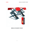
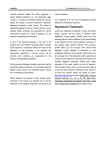
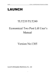
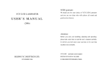
1
LAUNCH
TLT630A USER’S MANUAL
Copyright reserved! Without the written agreement
of Launch Shanghai Machinery Co., Ltd.
(hereinafter called “Launch”), no company or
individual is allowed to copy and backup this
manual in any form (electronic, mechanical,
photocopy, recording or other forms). This manual
is specifically designed for the use of Launch
product, and our company doesn’t undertake any
responsibility for various consequences caused as
a result of applying it to the guidance of operating
other equipment.
In case of the equipment damage or loss due to the
accident of the user himself or third party, abuse or
misuse of this equipment, unauthorized change
and repair of this equipment, or not conforming to
the operation and maintenance requirement of
Launch, Launch and its branches won’t undertake
any responsibility for the expenses and
expenditures generated.
For the equipment damage or problem caused as a
result of using other optional accessories or
consumables instead of original Launch product or
its recognized product, Launch won’t undertake any
responsibility.
Official statement: The purpose of other- productnames mentioned in this manual is to describe how
to use this equipment. Their registered trademarks
still belong to the original companies.
1
This equipment is for the use of professional
technical personnel or maintenance personnel.
Registered Trademark
Launch has registered its trademark in China and
several foreign countries, with the symbol of
LAUNCH. Other trademarks, service symbol,
domain name, icon, and company name of Launch
mentioned in this manual belong to the property of
Launch and its subsidiary companies. In the
countries where Launch’s trademark, service
symbol, domain name, icon and company name
haven’t been registered, Launch declares its
ownership on such unregistered trademark, service
symbol, domain name, icon and company name.
The trademarks of other products and company
names mentioned in this manual still belong to the
originally registered companies. Without prior
written agreement of the owner, nobody can use
the trademark, service symbol, domain name, icon
and company name of Launch and other
companies mentioned in this manual. If you have
any question, please visit website of Launch:
http://www.cnlaunch.com or write to Sales Dept. of
Launch Shanghai Machinery Co., Ltd. at No. 661
Baian Road, International Automobile City Auxiliary
Parts Park, Anting Town, Jiading District, Shanghai
City to contact Launch
LAUNCH
TLT630A USER’S MANUAL
Please read and understand
the manual before operation
z
z
z
z
z
Warning
z
z
z
z
This manual is an important part of the
product. Please read and understand it
thoroughly.
Keep the manual for future use in
inspection and maintenance.
Do not use the product for any other
purposes.
The manufacturer is not responsible for any
damage caused by improper use or uses
other than the designed purpose.
z
z
z
z
Precautions
z
z Only well-trained personnel can operate the lift.
Any changes to the components or use for
other purpose without the consent of the
manufacturer may cause direct or indirect
damage to the product.
z Do not expose the lift to extreme temperature
or humidity. Keep it away from heating
device, faucet, humidifier or furnace.
z Do not install the lift outdoors or expose it to
z
.
2
z
z
rain. If it is really necessary to do so, a
special order should be made from the
manufacturer.
Keep the lift away from the dust, ammonia,
alcohol, thinner and spray adhesive.
Keep away from the lift when it is in operation.
Inspection of the lift should be carried out
regularly. Do not operate a damaged lift or a
lift with broken parts. All the parts are only
replaceable with the parts provided by the
manufacturer.
Do not overload the lift. The maximum lifting
weight is clearly marked on the nameplate.
Do not operate the lift when there are
personnel in the vehicle.
Keep the lifting area clear of obstacle, grease,
oil, garbage and other substances.
Use the lifting point recommended by the auto
manufacturer. Keep the support in close
contact with the vehicle.
Use appropriate tools and safety protection
equipments such as overall and working
boots.
Pay special attention to the safety labels on
the control desk.
Keep hands and other body parts away from
the moving parts of a lift in operation.
Do not remove or override safety protection of
the lift.
Hydraulic oil for the lift is N32 or N46
mechanical oil. Pay attention to the safe
data as described in this manual.
For the sake of technical improvements,
Launch (Shanghai) Machinery Co., Ltd
reserves the right to change the specifications
without prior notice
LAUNCH
TLT630A USER’S MANUAL
Contents
1 General Information………………………………………4
1.1 Application…………………………..………………4
1.2 Features……………………………………………4
1.3 Specifications………………………………………..4
1.4 Environment Requirements………………………4
2 Structure……………………………………………….5
2.1 Layout…………………………………………………5
2.2 Electrical Diagram…………………………………6
2.3 Hydraulic Diagram…………………………………..6
2.4 Pneumatic Diagram…………………………………7
2.5 Operation Panel…………………………………….7
3 Operation……………………………………………….8
3.1 Preparatory Inspection……………………………….8
3
3.2 Operational Procedures………………………….8
3.3 Safety Precautions………………………………..8
4 Troubleshooting………………………………………..9
5 Maintenance……………………………………………10
5.1 Daily Maintenance………………………………10
5.2 Monthly Maintenance………………………………10
5.3 Biannual Maintenance……………………………10
5.4 Maintenance for 3 Years/5000 Operations………10
6 Storage and Scrapping……………………………10
6.1 Storage……………………………………………10
6.2 Scrapping……………………………………………10
Data of Grease and Oil…………………………………11
List of wear Parts…………………………………12
LAUNCH
TLT630A USER’S MANUAL
1 General Information
1.1 Application
This lift is designed for the purpose of lifting light
vehicles under 3.0 tons for vehicle test, service and
cleaning.
This machine can also be used as a lifting devise in
production lines, for material transportation and work
piece assembly.
1.2 Features
z
z
z
z
z
z
The lift features advanced design, durability,
compact layout.
The installation of base frames in the pits can
save space in the workshop.
Hydraulic system keeps both platforms level.
Mechanical protection device throughout the travel
distance.
Automatic height limiting device.
Automatic lubricating system and oil-less
bearings.
1.3 Specifications
Noise
Noise: ≤80dB (A)
Hydraulic System
Max. Working Pressure: 28 MPa, Flow rate: 5-6L/min.
Pneumatic System
Working Pressure: 5 kg/cm2
Max. Lifting Weight (kg)(lb)
3000(6614)
Max. Lifting Height (mm)(") 1750(69)
Lifting Time (sec)
≤50
Lowering Time (sec)
≥20
Power (kw)
2.2
Number of Platforms
2
Platform Size (mm)(")
1580×520(62.2×20.5)
Overall Weight (kg)(lb)
630(1389)
Synchronization
Precision
(mm)(")
Height difference (mm)
≤40(1.6)
≤8(0.3)
1.4 Environment requirements
Electric specifications:
Motor (Optional): 2.2kw
2850 r/min
Voltage options:
Single-phase/3-phase110v/220v 60Hz
Single-phase/3-phase220v/380v 50Hz
Temperature: 0℃ ~ +40℃
Relative Humidity: ≤80% at 30℃
Transportation/Storage Temperature: -25℃~+55℃
Altitude: ≤2000m(78740″)
4
LAUNCH
TLT630A USER’S MANUAL
2 Structure
2.1 Layout
L i m i t Switch
Fig.1
5
LAUNCH
TLT630A USER’S MANUAL
2.2 Electrical Diagram
AC200V/220V/380V-3P
T
~
380V ~
/220V
~
VD
AC220V--1P
HL
Ⅰ
~
Ⅰ:Lowering Solenoid Valve
Ⅱ:Air Valve
Ⅱ
Ⅲ
Ⅳ
Ⅲ:Time Relay Ⅳ:Relay
Fig.2
2.3 Hydraulic Diagram
F1、Slave cylinder hydraulic hose
Z1、Master cylinder hydraulic hose
13、Slave cylinder
12、Master cylinder
11、High pressure stop valve
10、Emergency lowering valve(manual control)
9、Lowering speed control valve
8、Lowering solenoid valve
7、Check-valve
6、Relief valve
5、Motor
4、Gear pump
3、Oil filter
2、Oil gauge/ Air blowhole
1、Oil tank
Fig.3
6
LAUNCH
TLT630A USER’S MANUAL
2.4 Pneumatic Diagram
1.Air filter and lubricator
2.Solenoid air valve
P
3.Air cylinder on master platform
4.Air cylinder on slave platform
Fig.4
2.5 Operation Panel
POWER
UP
EMG.STOP
DOWN
Fig.5
7
SAFETY LOCK
LAUNCH
TLT630A USER’S MANUAL
3 Operation
3.1 Preparatory Inspections
y
y
y
y
y
y
y
y
Check for the synchronized and steady
movement of the platforms.
Check the sensibility and reliability of safety
ratchet.
Make sure the platforms would automatically
stop when they reach the max lifting height
(2000mm/79inches)
Check for possible leakage in the cylinder,
hoses and fittings.
Check for possible air leakage in the solenoid
valve, cylinder, pressure regulator valve and
fittings.
Check for any abnormal action and sound in
pump and motor.
Check if the Emergency Stop button works
properly.
y
Press SAFETY LOCK button to lower the lift and
engage the safety ratchet so that the platforms
are leveled with one another.
After the maintenance is done, keep the work
area clear and safe before lowering lift.
3.3 Safety Precautions
y
y
y
y
The hydraulic relief valves are well-adjusted
before leaving factory. The manufacturer will
not be responsible for any damage caused by
unauthorized adjustment.
Check the safety lock ratchets are engaged
before going about any under-car jobs.
Place rubber pads on the platforms and spread
them for maximal support.
In case of any leakage in the hydraulic system,
fix the problem and refill the oil to the proper
level.
3.2 Operational Procedures
y
y
y
y
y
Keep speed below 5km/h when driving on the
platforms.
Stop the vehicle when the platforms are
between its front and rear wheels.
Place rubber pads on the platforms where the
lifting points will contact and press UP button to
lift the vehicle to 200mm~300mm (9 to 12 inches)
from the floor.
Make sure that the two platforms are leveled
and nothing unusual is found.
Keep pressing UP button until the vehicle rises
to the required height.
8
Caution: Once the safety ratchets are fully in place,
the LOCK button should be released immediately. If
the Lock button is pressed for too long, too much oil
would flow back from cylinder. In this case, the safety
ratchets can not be completely released from locked
position within the set time for the platforms to go up
when the DOWN button is pressed. This can result in
no lowering action, or lowering of only one platform,
which may cause the vehicle to fall from the lift. (Please
refer to the Working Principles of the lift)
LAUNCH
TLT630A USER’S MANUAL
4 Troubleshooting
Symptoms
The motor does not work.
The motor works, but the
platforms do not move, or
can only go up slowly.
The motor works, but the
platforms can not lift the
vehicle.
The lift is too slow in
lowering.
The platforms are not
synchronized.
Safety ratchets cannot be
separated from serration.
Reasons
Thermo relay or circuit breaker actuated
Voltage is not correct.
Electrical wiring is wrong.
Motor is broken.
The motor rotates in the wrong direction.
Oil level is too low.
Height limit switch is stuck or damaged.
The voltage to the motor is too low.
Pressure of relief valve is not right.
The lift is overloaded
The hydraulic pump is damaged.
There is foreign substance in the lowering
solenoid valve.
Lowering speed valve is turned too low.
There is air in upper chamber of Master
Cylinder or Slave Cylinder.
The oil supply can not be cut off because of
the leakage of stop valve.
Leakage in hydraulic system
The air pressure regulating valve is closed
or too low.
The Solenoid air valve is damaged.
The LOCK button is pressed for too long
time.
9
Solutions
Reset the thermo relay or circuit breaker
Supply power of correct voltage.
Fix the wiring.
Change motor.
Exchange wiring of motor to change
direction.
Add oil.
Repair or replace the height limit switch.
Supply motor with correct voltage.
Adjust the pressure of relief valve.
Check the weight of the vehicle.
Replace the hydraulic pump.
Clean the lowering solenoid valve.
Turn the lowering speed valve up.
Air bleeding performance is needed.
The air in the master and slave cylinder
can be bled after the platform goes up
and down several times.
Replace stop valve.
Replace the seal or the cylinder.
Adjust air pressure to 5kg/cm2
Replace the solenoid air valve.
Release the LOCK button immediately
after the safety ratchets are fully
engaged.
LAUNCH
TLT630A USER’S MANUAL
5 Maintenance
y
5.1 Daily Maintenance
y
y
y
y
y
Keep the lift clean. Make sure power is cut off
before cleaning the lift.
Keep the working area clean. Excessive dust
in the work area will shorten the lifespan of the
lift.
Before operation, inspect and keep all the safety
devices of lift in order. If any problems are
found, adjust, maintain or replace the parts in a
timely manner.
Make sure that the pits are kept dry and clean.
Inspect if there is leakage in the air valve and if
it is well-lubricated.
5.2 Monthly Maintenance
y
y
Refasten the anchor bolts.
Check all the hoses and fittings for possible
wearing and leakage. If any leakage is found
to be caused by worn sealing parts, replace with
y
parts meeting the specifications.
Check if the roller slide is well-lubricated with
high-quality #2 lithium lubricant.
Apply #2 lithium lubricant on a monthly basis.
5.3 Biannual Maintenance
y
y
y
Check all the moving parts for possible wearing,
interference and damage.
Inspect the lubrication of all the rollers. If the
roller is dragged along in lifting or lowering,
apply lubricant to the roller shaft.
At the end of the first six months, clean the
hydraulic system and replace the hydraulic oil.
Replace the hydraulic oil with N32 hydraulic oil
in winter and N46 in summer.
5.4 Maintenance for 3 Years or
5000 Times Operations
y
y
y
Replace the bushings at all joints.
Replace all seals
Replace the rollers.
6 Storage and Scrapping
6.1 Storage
When the lift needs to be stored for a long time:
y Unplug from power socket.
y Lubricate all the parts, including all the contact
surface of the rollers.
y Bleed oil from tanks.
y Cover the lift with plastic hood.
10
6.2 Scrapping
When the lift has exceeded its lifespan and can not be
used any more, disconnect it from the electrical supply
and dispose of as required by the local regulations.
LAUNCH
TLT630A USER’S MANUAL
Hydraulic Oil Data
#2 Lithium Lubricant
Item
Conical degree(1/10mm)
Dropping point ℃
Erosion(T2 Copper Plate,100 ℃,24h)
Copper Screening(100℃,22h)%
Evaporation(100℃,22h)%
Oxidizing Stability (99℃,100 h)
Non-corrosibility(52℃,48)
Foreign substance(Microscopic method)/
(number/cm³)
Above 10µm
Above 25µm
Above 75µm
Above 125µm
Relative Viscosity
(-15℃,10s-1 ),/(Pa·s)
Humidity Loss(38℃,1h)(%)
Specifications
278
185
No Change
4
2
0.2
Grade 1
Fewer than 5000
Fewer than 3000
Fewer than 500
0
<800
≥8
N32 Mechanic Oil (for winter)
Item
Moving Viscosity 40℃
Pour /℃
Flash point /℃
Specifications
28.8~35
≤-15
≥175
N46 Mechanical Oil (for summer)
Item
Moving Viscosity 40℃
Pour /℃
Flash point /℃
Specifications
41.4~50.6
≤-9
≥185
11
LAUNCH
TLT630A USER’S MANUAL
TLT630A Wear Parts
NO
CODE
NAME & SPEC
USE FOR
QTY
1
GB1235-76
O-ring 105x3.1
Master cylinder
2
2
GB1235-76
O-ring 35x3.1
Master and slave cylinder
2
3
GB1235-76
O-ring 95x5.7
Slave cylinder
1
4
GB10708.3-89
Dust proof ring FC45x53x5
Master and slave cylinder
1
5
S55044
Seal-ring 105x89.5x6.3
Master cylinder
1
6
S55044
Seal-ring 95x79.5x6
Slave cylinder
1
7
S55013
Seal-ring GS45x60.5x6
Master cylinder
1
8
GB10708.1-89
Shaft sealing ring GY45x55x7
Master cylinder
1
9
103040157
Seal gasket 14
5
10
103040158
Seal gasket 16
5
11
104130182
Z8 Seal
12
102990070
Air connector APL6-01
2
13
102990071
Air connector APL6-02
2
14
102160380
T air connector APE6
1
12
Air cylinder
2