1
WatchDog 100 / 100P User Manual ITWatchDogs, Inc. 7600 N. Capital of Texas Hwy. Suite B-345 Austin, TX 78731 USA http://www.itwatchdogs.com Tel: (512)-257-1462 Fax: (309)-406-3651 Copyright Information © Copyright 2009-2012 ITWatchDogs All Rights Reserved. No part of this document may be used or reproduced for commercial benefit in any form or by any means, or stored in a database or retrieval system, without prior written permission of ITWatchDogs, except in case of brief quotations embodied in articles or reviews. Making copies of this document for any purpose other than your own individual use is a violation of United States copyright laws and international treaty provisions. For further information, contact ITWatchDogs as directed below. Warning and Disclaimer This publication is provided as-is, without warranty of any kind, either express or implied. While every precaution has been taken in the preparation of this publication, and the information contained within was believed to be correct at the time it was written, ITWatchDogs assumes no responsibility for errors or omissions. Neither is any liability assumed for damages resulting from the use of the information or instructions contained herein. It is further stated that the publisher and authors are not responsible for any damage or loss to your data or equipment that may result, directly or indirectly, from your use of this publication and the related software or hardware. Nothing in this documentation shall be construed as conferring any license under any of ITWatchDogs’ or any third party’s intellectual property rights, whether by estoppel, implication, or otherwise. This equipment has been tested and found to comply with the limits for a Class A digital device, pursuant to part 15 of the FCC Rules. These limits are designed to provide reasonable protection against harmful interference when the equipment is operated in a commercial environment. This equipment generates, uses and can radiate radio frequency energy and, if not installed and used in accordance with the instruction manual, may cause harmful interference to radio communications. Operation of this equipment in a residential area may cause harmful interference, in which case the user may be required to correct the interference at his own expense. Modifications to this product not authorized by ITWatchDogs could void the FCC approval and negate your authority to operate the product. Trademark Acknowledgements ITWatchDogs, the ITWatchDogs logo, the “Digger” mascot character, itwatchdogs.com, WeatherGoose, SuperGoose, MiniGoose, MicroGoose, RelayGoose, WatchDog, are trademarks or registered trademarks of ITWatchDogs. Any other trademarks, products, or company names mentioned herein are the property of their respective owners, and are used strictly for the purposes of identifying compatibility and/or providing examples of the proper use of ITWatchDogs’ products in conjunction with the identified product(s) or service(s). In no case should the use of such trademarks be regarded as affecting the validity of any trademark or service mark; neither should it be construed either as an endorsement by ITWatchDogs of the trademarked product(s) or service(s), or as an endorsement of ITWatchDogs or its products by the trademark or service mark’s owner(s). Sales, Support & Contact Information To receive further information or assistance regarding this publication, or with any ITWatchDogs products, please contact: Headquarters: ITWatchDogs 7600 N. Capital of Texas Hwy. Suite B-345 Austin, TX 78731 USA Phone: Fax: (512)-257-1462 (309)-406-3651 E-mail: sales inquiries, price quotes: sales@itwatchdogs.com technical assistance, RMA requests: support@itwatchdogs.com Web: www.itwatchdogs.com Contents Preface..................................................................................................................................................................2 Introducing your WatchDog-100............................................................................................................................3 Unpacking your WatchDog-100:......................................................................................................................................4 Specifications........................................................................................................................................................7 Hooking up the WatchDog-100.............................................................................................................................8 Connecting the external power supply: ...........................................................................................................................9 Attaching the optional mounting brackets:.......................................................................................................................9 Connecting the Ethernet network cable: .......................................................................................................................10 Connecting analog sensors to the analog-input channels: ............................................................................................10 Connecting external equipment to the control-relay output: ..........................................................................................13 Connecting external Digital Bus Sensors: .....................................................................................................................15 Initial Setup (A “quick-start” guide to giving the unit an IP address)..................................................................16 Configuring the WatchDog-100...........................................................................................................................18 Getting to the Configuration page: ................................................................................................................................19 Restoring the unit’s default settings: ..............................................................................................................................19 Assigning an IP Address (Network configuration settings): ...........................................................................................20 Setting the real-time clock: ............................................................................................................................................20 Setting an E-mail server & addresses: ..........................................................................................................................21 SNMP events and managers (SNMP configuration settings): .......................................................................................22 Access control (User Accounts configuration settings): ................................................................................................22 Setting unit-identification and contact information..........................................................................................................23 IP Camera configuration settings: .................................................................................................................................23 Syslog-based Diagnostics settings: ...............................................................................................................................24 Installing firmware updates: ...........................................................................................................................................24 Choosing Fahrenheit or Celsius temperature scales: ...................................................................................................25 Enabling the RPM-X2’s relays as alarm actions: ..........................................................................................................25 Using the WatchDog-100....................................................................................................................................26 Viewing the current readings via the Overview page displays: .....................................................................................27 Assigning “friendly” names to the sensor devices: ........................................................................................................28 To change the “friendly-name” label of the WatchDog-100:....................................................................................28 To change the “friendly-name” labels of attached Digital-Bus sensors:..................................................................28 To change the “friendly-name” labels of sensors connected to the Analog Input channels:...................................29 To change the “friendly-name” labels on the dry-contact Control Relay:.................................................................29 Disconnected, or “unplugged” sensors:..........................................................................................................................30 “Unavailable” sensors?:...........................................................................................................................................30 Applying an offset to the internal temperature reading:..................................................................................................31 Viewing the logged data as a graph:..............................................................................................................................32 Managing the WatchDog-100’s data-logging:................................................................................................................33 To download logged data from the WatchDog-100:................................................................................................33 To clear the WatchDog-100’s logging memory:.......................................................................................................33 Downloading the current readings as XML data: ..........................................................................................................33 Changing the range scaling & units of measurement on the WatchDog-100’s Analog-Input channels:........................34 Downloading the .MIB files for SNMP: ..........................................................................................................................34 Configuring the dry-contact control relay: ......................................................................................................................35 Setting alarm thresholds and actions: ...........................................................................................................................36 Setting alarms on the WatchDog-100’s built-in temperature & humidity sensors:...................................................36 Setting alarms on sensors attached to the WatchDog-100’s analog-input channels:..............................................38 Setting alarms on remote sensors attached to the Digital Sensor Bus:...................................................................39 Removing unwanted alarms from the list:................................................................................................................39 Identifying tripped alarms on the web page:............................................................................................................40 Using Analog-Input sensors – some practical examples: ..............................................................................................41 Using Dry-Contact Sensors:....................................................................................................................................41 Using Conductivity-type Sensors:............................................................................................................................43 Calculating Appropriate Max Scaling for Conductivity-type Sensors:......................................................................44 Using Proportional-Voltage Sensors:.......................................................................................................................45 Calculating Appropriate Max Scaling for Proportional-Voltage Sensors:.................................................................46 Using the dry-contact control relay: ...............................................................................................................................47 Triggering the relay when alarm threshold(s) are exceeded:..................................................................................47 Triggering the relay manually:..................................................................................................................................48 Using the relay in “Normal” vs. “Latching” modes:...................................................................................................48 Appendix A: Some Free E-mail Services’ SMTP Configurations.......................................................................49 Appendix B: Potential SMTP issues when using Exchange Servers.................................................................50 Preface About this Manual: This manual is designed to help you set up and use your WatchDog-100 Monitor. The first chapter will provide you with a basic introduction to the WatchDog-100 itself, along with instructions on how to properly install and connect it; subsequent chapters will explain each of the WatchDog-100’s functions in detail. Note: this manual assumes that the user has at least some basic familiarity with connecting Internetcapable devices to an internal network or LAN, including how to properly configure any routers or switches to allow the monitoring unit to be reached via a web browser on a host PC within that network, and to allow the unit to reach other devices or services (i.e. IP cameras, e-mail servers, NTP services, etc.) which your application may require. Obtaining Related Documentation: This manual is specifically concerned with the WatchDog-100 monitoring unit itself. For more information concerning the various sensors and accessories available for the monitoring unit, refer to the appropriate manual for the specific accessory in question. These manuals can be downloaded from our web site, in the Support→Documentation section here: http://www.itwatchdogs.com/documentation.aspx Document Conventions: This document uses some or all of the following conventions: system messages Messages which the unit displays to the user are shown in monospaced italic “Courier” user-typed commands Information you must enter is shown in monospaced “Courier” [KEY] Square brackets are used to indicate that the user should press a specific key or keys on the user’s PC keyboard; i.e. [ENTER] means the user should hit the “Enter” key, as opposed to typing the word “enter”. [CTRL][C] means to hit the “control” and “c” keys together. web page controls The names of buttons or control boxes on the unit’s web page are shown in Arial italic. <user setting> Elements which the user must fill in with their own specific information are shown in italics between angle brackets; i.e. <ip address>, <account name> Note: Text highlighted in yellow means reader take note. Notes contain suggestions or cautions which the reader should keep in mind when trying to use a particular feature of the product. Warning: Text highlighted in red means reader be careful! Warnings indicate situations where equipment damage, malfunction, or data loss could result if the highlighted information or instructions are not followed by the user. ►Modelspecific ►information Information which only applies to one or more specific models will be highlighted in grey, with an ►arrow preceding the text. WatchDog-100 User Manual [2] rev. 140307A Introducing your WatchDog-100 Designed specifically for smaller-scale applications, the WatchDog-100 combines several of the WeatherGoose series-II’s most popular and useful features into a compact, reduced-cost unit with a simplified, easier-to-use web interface. With a built-in temperature & humidity sensor, a Digital Sensor Bus port, four analog-sensor inputs, and a single dry-contact control relay, the WatchDog-100 provides a flexible and sophisticated monitoring solution for small-office server closets, remote telecommunications-equipment sites, climate-controlled storage facilities, or other areas where space is at a premium. The WatchDog-100 comes in two models: The standard “WatchDog-100” model, and the enhanced “WatchDog-100P” model which includes Power-over-Ethernet (PoE) capability. Aside from the PoE option, both models function identically, so in general the term “WatchDog-100” or “monitoring unit” will refer generically to both models in this manual. If it is necessary to point out behavior or information which only applies to a specific model, such model-specific information (and the model it applies to) will be highlighted in grey. In this introductory section, you will find illustrations of the WatchDog-100 and its front-panel connections, along with brief explanations of the unit’s various features and a summary of its specifications. NOTE: The information provided in the following sections applies to WatchDog-100 units running at least firmware version v1.5.1. Earlier firmware versions may not have all of the capabilities described, while later versions may have additional capabilities not included in this version of the manual. If in doubt, please consult our web site for change-logs, manual updates, or errata sheets which may apply to your particular model and firmware revision. WatchDog-100 User Manual [3] rev. 140307A Unpacking your WatchDog-100: When you first open up the box your WatchDog-100 came in, you should find the following items. (Note that the actual appearance of the devices you received may vary slightly from the sample illustrations shown here.) WatchDog-100 RELAY OUTPUT TIV AC IDL E E ANALOG INPUTS Dry Contact / 0-5VDC C1C2 C3 C4 6VDC ON ETHERNET IP RESET N N C C O DIGITAL SENSORS +6VDC power supply • Input voltage range: • Output voltage: • Operating temperature range: 100 ~ 240VAC, 50/60Hz +6VDC, 2A (max.) 0 – 40°C / 32 – 104°F (typ.) This power supply is capable of worldwide-voltage (120~240VAC, 50/60Hz) operation, and connects to the WatchDog-100 via a standard 2.1mm center-positive DC barrel plug. WARNING: Using any DC power supply other than the model(s) supplied or approved by ITWatchDogs may damage your WatchDog-100 and void your warranty! If the standard +6VDC wall transformer-style power supply is not suitable for your application, please contact ITWatchDogs’ sales & service department to discuss possible alternatives. The standard +6VDC power supply normally supplied with the WatchDog-100 comes with a U.S.-style (NEMA 5-15, ungrounded) plug. Power supplies with a U.K.-style (BS 1363) plug, or with a “universal” kit of interchangeable U.S. / U.K. / European (CEE 7/4) / Australian (AS 3112) plugs, are available as an option. Rack-mount brackets & hardware The WatchDog-100 also comes supplied with a pair of 1-U mounting brackets, to allow the unit to be mounted in a standard 19” rack-mount cabinet if desired. These will normally already be mounted to the unit when you first receive it, since they help keep the unit from moving around inside the box during shipment, but can be easily removed with a Philips-head screwdriver if you wish to mount the unit some other way. WatchDog-100 User Manual [4] rev. 140307A Below is a quick overview of the physical connections and indicators on the front panel of the WatchDog-100. (Note: the sample diagrams shown below have been simplified for clarity; the actual physical appearance of the unit may vary slightly.) RELAY OUTPUT TIV AC IDL E E ANALOG INPUTS Dry Contact / 0-5VDC C1C2 C3 C4 6VDC ON A B ETHERNET C D IP RESET E N N C C O F DIGITAL SENSORS G H A DC power jack and LED: The +6VDC power supply’s 2.1mm, center-positive barrel plug fits into this socket to provide power to the WatchDog-100. The green LED next to the power-supply jack will illuminate when the WatchDog-100 is receiving DC power from the power supply. B Ethernet jack: This jack features two green LEDs indicating the connection status. The LED on the right indicates “link/active”; it will light up solidly when the unit is physically connected to the network (“link”), and blink when the unit is being accessed (“active”). The left-hand LED indicates the link speed; when lit, it indicates a 100Mbit connection. C Active / Idle LEDs: Located in between the Ethernet jack and IP RESET button, these serve as indicators that the WatchDog100 is operating properly and communicating with the sensor-bus controller and external sensors (if any). The “Idle” LED will normally blink approximately once a second while the WatchDog-100 is operating, while the “Active” LED will light up when the main CPU is actively exchanging data with the internal or external sensors via the bus controller. D IP RESET button: Holding down this button for approximately 15 seconds, until both the Active and Idle LEDs light up solidly (no blinking pattern), will reset the unit’s IP address to the factory default of 192.168.123.123. It will also clear any User Accounts username/password settings on the Config tab, allowing you to regain access to the unit even if you’ve forgotten your passwords or accidentally misconfigured the unit’s settings. If you power-cycle the unit (disconnect and reconnect power) while keeping this button held down, it will completely erase all settings and return the WatchDog-100 to its “out-of-the-box” factory configuration. Keep the button held down for at least 5 seconds after reapplying power to ensure the factory reset occurs properly. E Analog Inputs: External analog-type sensors are connected to the WatchDog-100’s four (4) analog-input channels via this 8-position terminal block. Each analog input consists of two terminals; a “C”, or Common (DC ground) terminal, and a numbered terminal which corresponds to the ID of that particular analog-input channel. By default, these inputs are identified as “AI1” through “AI4” on the WatchDog-100’s web page, but these names can be changed to something more meaningful via the unit’s Display page. (More information about this, and about the general behavior of the analog inputs with various types of sensors, will be described and illustrated in more detail in the chapter concerning the use of the analog-inputs channels. Specific information concerning the behavior of a particular analog-sensor model can be found in the user guide for that sensor.) WatchDog-100 User Manual [5] rev. 140307A Unlike the Digital Sensor Bus, there is no fixed limit on the length of the wiring used to connect analog sensors; however, users are cautioned that excessively long cable runs may be prone to picking up ambient electrical and radio-frequency noise from other equipment in the room, which may interfere with the sensor readings and make them appear noisier or less accurate than usual. Therefore, ITWatchDogs recommends keeping the cable runs between the WatchDog-100 and the attached sensors as short as possible, to minimize this effect. F Control Relay outputs: To the right of the Analog-Input terminals is a dark-green, 3-position terminal block which provides access to the control relay’s dry-contact pairs. This control relay can either be configured to energize automatically in response to an alarm condition, or it can be energized and de-energized manually by the user via the Control page. Both the Normally-Open (NO) and Normally-Closed (NC) contacts are provided, so that you can choose whichever action is appropriate for your particular application. (Relay actions will be described and illustrated in more detail in the following chapters, specifically those concerning setting alarm thresholds from the Alarms page and and configuring the control relay options from the Control page.) Underneath the relay terminals is an LED which indicates the relay’s current status. A red LED indicates that the relay is currently de-energized, and that the NC pair is closed; a green LED indicates that the relay is currently energized and that the NO pair is closed. (Note that when discussing relay-contact actions, “normally” refers to the relay’s de-energized state.) G Temperature/Humidity sensor tab: The WatchDog-100’s built-in temperature and humidity sensors are mounted here, protected by a metal cage around the circuit-board tab. The unit should be mounted in such a way that this tab is exposed to the environment to be monitored. H Digital Sensor jack: This 6P6C modular jack allows you to connect one or more Digital Bus-type sensors to the WatchDog-100. Note that while only a single front-panel jack is provided, the WatchDog-100 will support up to four external sensors with the use of a passive port splitter. (This will be illustrated in the sample hookup diagrams later in this section.) The Digital Bus-type sensors used by the WatchDog-100 are the same as those used by the WeatherGoose series. The WatchDog-100 supports all of the existing single-function sensors, such as RT-series temperature sensors, RTAFHD3 temperature/airflow/humidity probes, and the RPM-X2 Remote Power Manager. Complex multifunction accessories such as the IOE I/O Expander, however, are not supported due to their large datastorage requirements; generally, these devices are better suited to the WeatherGoose-II series. Also note that the WatchDog-100 does not support discontinued “legacy” devices such as the RTAF2 or RTAFH2 airflow probes, or the PowerEgg series of AC power monitors. NOTE: the WatchDog-100 has a maximum limit of 600 ft. of total cable length on the Digital Sensor Bus; i.e. you can have a single external sensor 600ft away from the unit, or two sensors with 300 ft. cables, or two at 100 ft. plus two at 200ft., or any other combination of cable lengths as long as (A) the number of sensors does not exceed four, and (B) the cable lengths do not add up to more than 600 ft. total. WatchDog-100 User Manual [6] rev. 140307A Specifications • Power requirements – WatchDog-100 unit: +6VDC 140mA (0.84W) typ. (no external sensors, relay not used) 350mA (2.1W) max. (4x RTAFHD3 sensors; relay in use) • Power requirements – AC Power Adapter: (included w/unit) 100 ~ 240VAC, 50/60Hz • Power requirements – Power-over-Ethernet: IEEE 802.3af-compliant (48VDC, 1W typ.) (WatchDog-100P model only) • Inputs: 4 analog-input channels (8-position terminal block) 1 Digital Sensor Bus connection (1x 6P6C modular jack) • Outputs: 1 dry-contact relay, SPDT (3-position terminal block) • Analog Input voltage range: 0 ~ +5VDC • Analog Input sampling rate (internal): 5 seconds (approx.) • Analog Input sampling accuracy: ±2% (typ.) • Log-Data Capacity: 1Mb (1024Kb) • Log-Data Rate: (built-in sensors only*): 20Kb/day (approx.) • Relay contact ratings: 0.5A @ 60VDC 1A @ 30VAC(rms) • Maximum Digital Sensor Bus cable length: 600ft (182m) • Operating Temperature Range: 0° ~ +70°C (+32° ~ +158°F)† • Supplied Accessories: (1x) AC Power Adapter, 100~240VAC in, +6VDC out (2x) 19-inch 1U rackmount brackets * Remote Digital Bus sensors will require an additional 3 ~ 12Kb per day, approximately, depending on the sensor type. Remote sensors connected to the built-in analog-input channels are considered to be part of the built-in sensor package, and do not require additional data-logging memory. † Note: typical operating range of the included AC power supply is 0 – 40°C (32 – 104°F). For operation outside of this temperature range, ITWatchDogs recommends using either Power-over-Ethernet, or using a power supply designed specifically to operate at extended temperature ranges instead of the included power supply. WatchDog-100 User Manual [7] rev. 140307A Hooking up the WatchDog-100 Once you have unpacked the WatchDog-100 and verified that all of the accessories are in the box, the next step is to mount the unit in an appropriate location and connect it to your network. The following sections will provide illustrated examples of how to: • Attach or remove the optional 19-inch 1U rack-mount brackets • Connect the external power supply • Connect the unit to your network via the Ethernet jack • Connect external Digital Sensor Bus sensors to the sensor jacks • Connect external analog sensor devices to the analog inputs • Connect an accessory device to the control-relay contacts WatchDog-100 User Manual [8] rev. 140307A Attaching the optional mounting brackets: The WatchDog-100 fits in between the two mounting brackets, as illustrated here. The brackets are held on by two or more Philips-head screws on each side of the WatchDog-100 unit. Typically, the unit will be shipped with the brackets already installed; if you do not intend to mount the unit in a 19” rack, the brackets can be easily removed simply by removing the screws holding them to the sides of the unit. Be sure to save the screws in case you later wish to re-mount the brackets. RELAY OUTPUT TIV AC IDL E E ANALOG INPUTS Dry Contact / 0-5VDC C1C2 C3 C4 6VDC ON ETHERNET IP RESET N N C C O DIGITAL SENSORS Connecting the external power supply: The 6VDC power supply’s barrel-plug connector fits into the matching socket, marked “6VDC”, on the WatchDog-100 as shown below. ►Note: even if you purchased the PoweroverEthernet capable WatchDog100P model, and intend to use the PoE feature to power the unit instead, it may still be necessary to connect the 6VDC power supply while performing the initial setup and configuration, as the built-in Ethernet ports on most desktop and laptop PCs are generally not equipped to power external devices via PoE. The WatchDog-100 contains internal protection circuitry to prevent both power-supply sources from getting cross-connected if both PoE power and the 6VDC power supply are connected simultaneously. RELAY OUTPUT TIV AC IDL E E ANALOG INPUTS Dry Contact / 0-5VDC C1C2 C3 C4 6VDC ON ETHERNET WatchDog-100 User Manual IP RESET DIGITAL SENSORS N N C C O [9] rev. 140307A Connecting the Ethernet network cable: Connecting the WatchDog-100 to your network is as simple as plugging a standard Ethernet cable into the Ethernet jack, as shown here. If the connection is successful (and the WatchDog-100 has power, of course), the right-hand LED (“link/data”) will illuminate. The “link/data” LED will also blink when the unit is actively transferring data across the network connection. The left-hand LED (“speed”) illuminates whenever the unit is connected to a 100Mbit network connection. If the network connection is only 10Mbit-capable, the “speed” LED will remain unlit. RELAY OUTPUT TIV AC IDL E E ANALOG INPUTS Dry Contact / 0-5VDC C1C2 C3 C4 6VDC ON ETHERNET IP RESET N N C C O DIGITAL SENSORS Connecting analog sensors to the analog-input channels: The WatchDog-100 provides four separate analog-input channels, suitable for connecting any sensor of the following types: • Dry-contact pairs: Essentially, a “dry contact” is simply a switch or relay which is either open or closed, but which doesn’t provide any actual voltage or current of its own; i.e. it’s up to the monitoring device to provide a suitable loop current to sense the state of the contacts. Examples of this type of sensor would include the MS-1 Magnetic Door Switch, or the relay outputs of the WaterSnake Water Detection System. Many backup-generator and HVAC control systems also provide status outputs of this type. • Conductivity sensors: This type of sensor changes its electrical resistance based on the condition it’s sensing. The most common example of this type of sensor is water or liquid detectors, such as the WD-1 Water Sensor. This type of sensor starts off with a near-infinite resistance when dry; then, its resistance drops rapidly when water or other conductive liquids bridge the gap between the metal contact points, allowing current to flow between the contacts. • Proportional voltage-output sensors: These types of sensors output an analog signal voltage proportional to the condition being sensed or monitored. Examples of this type of sensor would be the CT30-60-120 Current Transformer, which puts out a 0 ~ 5Vdc signal which is proportional to the current being drawn through the wire which is passing through the center of the transformer (i.e. if 15 amps is passing through the wire, and the CT30-60-120 is set to the 0~30 amp range, then the signal voltage will be ≈2.5Vdc); or the RCP2-100 City Power Monitor, which puts out a steady ≈4.3V “power good” signal as long as the AC power socket it’s plugged into is “live” (incoming AC line voltage is present at the outlet), and drops its signal voltage to <0.5V if a blackout or brownout causes the AC line voltage to drop below ≈85VAC. WatchDog-100 User Manual [ 10 ] rev. 140307A The analog inputs on the WatchDog-100 can accept a signal voltage range of 0~5Vdc. If you are trying to connect a 3rd-party sensor device (i.e. a device not manufactured or sold by ITWatchDogs), make certain that its signal output falls within this range; if the sensor device puts out a different signal-voltage range, or uses a 0~20mA current-loop arrangement instead of proportional voltage, you will need to check with the sensor’s manufacturer to see if they offer a similar sensor with the correct output range, or a signal-conditioning “bridge” which can convert the sensor’s output to a 0~5Vdc signal. As shown here, each analog input channel consists of two positions on the terminal block. The terminal marked “C” is the Common, or DC ground, terminal, while the numbered terminal is that particular input channel’s ID number. For sensors which have no polarity, such as dry-contact devices, the order of the wires is irrelevant; however, for sensors which do have a specific DC voltage polarity, such as proportional-output sensors or sensors which use a solid-state transistor output rather than a physical switch, always be sure to connect the wires in the correct order. WARNING: Reversing the polarity of the wires on such sensors will result in incorrect sensor behavior, and may damage the sensor and/or the WatchDog-100 itself! ANALOG INPUTS Dry Contact / 0-5VDC C1C2 C3 C4 Each terminal on the Analog Input block is opened and closed by pressing the white button above each terminal opening, as illustrated below: 1: Push the white button inwards using your fingernail or the tip of a small screwdriver. (Note: using a pen or pencil is not recommended, as this could allow ink or graphite particles to get into the contacts.) WatchDog-100 User Manual 2: While continuing to keep the white button pressed in, insert the wire into the opening underneath the white button. Make sure at least 1/4in. (≈0.7cm) of the insulation is stripped off the end of the wire before insertion, or the wire will not make contact inside the terminal block. [ 11 ] 3: Then, simply release the white button to allow the spring-loaded jaws inside the terminal to grip the exposed portion of the signal wire inside the terminal. rev. 140307A Shown here is an example of the different types of analog devices which can be connected, and the proper means of connecting them. Again, note the importance of observing proper polarity when connecting any sensor which generates an actual 0~5Vdc signal voltage. ANALOG INPUTS Dry Contact / 0-5VDC ANALOG INPUTS Dry Contact / 0-5VDC C1C2 C3 C4 C1C2 C3 C4 DRY CONTACTS: True dry-contact devices – such as magnetic door switches or relay contacts – do not have an intrinsic DC voltage polarity; therefore, as illustrated above, the actual order of the wires in each pair is irrelevant. They can be connected to the WatchDog100’s input terminals either way, and the sensor will still work as intended. WatchDog-100 User Manual PROPORTIONAL VOLTAGE-OUTPUT SENSORS: CONDUCTIVITY SENSORS: The same is also true of nonpolarized conductivity sensors, such as the WD-1 Water Sensor. While the cable attached to them may come with colored red/green or red/black wire pairs, these sensors also have no intrinsic DC polarity, and the actual order of the wires is irrelevant to the functioning of the sensor. [ 12 ] Sensors such as the SA-1 Smoke Alarm, which use a solid-state transistor output rather than a drycontact switch, or the RCP2-100 which puts out a proportional voltage signal, do have an inherent DC voltage polarity and must be connected correctly! The DCground, or negative (–), side must be connected to the C (common) terminal; while the output signal, or positive (+) side, must be connected to the numbered input terminal. Incorrect hookup may damage the sensor or the WatchDog-100! rev. 140307A Connecting external equipment to the control-relay output: The WatchDog-100 provides a control relay which can either be set to energize when a sensor exceeds a particular threshold you’ve set, or which can be energized and de-energized manually via the Control page. The relay is an SPDT (Single-Pole Double-Throw) type; both the Normally-Open (NO) and Normally-Closed (NC) contacts are provided, so that you can choose whichever action is appropriate for your particular application. The relay connections are suitable for switching low-voltage loads such as signal lights and sirens, and even small low-voltage motors such as a 12VDC fan or an air pump, so long as the load does not draw more than 30W. However, they are not suitable for directly controlling equipment that runs off line voltage (120/208/240VAC) or draws high currents, such as water pumps, or air conditioners, or lead-acid battery chargers. Warning: attempting to switch high-voltage or high-current loads directly via the relay contacts may permanently damage the unit! The maximum ratings of the relay contacts are as follows: • 0.5 Amps @ 60 Volts DC • 1 Amps @ 30 Volts AC(rms) • 30 Watts maximum Watts = Volts X Current; so, a device running on 30VAC may draw up to 1A, while a 60VDC load may only draw 0.5A. The control-relay terminals are of a standard screw-terminal design; to connect your external device’s wires to the terminals, use a small flat-blade screwdriver to open and close the terminal jaws, as illustrated below: 1: Using a small flat-blade screwdriver, turn the screw above the desired terminal opening several turns counterclockwise to open the terminal. 2: Insert the wire into the open terminal. Make sure at least 1/2in. (≈1.3cm) of the insulation is stripped off the end of the wire before insertion, or the wire will not make proper contact inside the terminal block. 3: Turn the screw above the desired terminal opening several turns clockwise, until the wire is securely gripped by the terminal. RELAY OUTPUT RELAY OUTPUT RELAY OUTPUT N N C C O N N C C O N N C C O WatchDog-100 User Manual [ 13 ] rev. 140307A The diagram below illustrates a typical example of using the control-relay output in conjunction with a telephone auto-dialer, to allow the monitoring unit to alert the appropriate personnel via a phone call even if the facility’s internal network is down: RELAY OUTPUT AC IDL E TIV E ANALOG INPUTS Dry Contact / 0-5VDC C1C2 C3 C4 6VDC ON IP RESET ETHERNET N N C C O DIGITAL SENSORS TAMP TR2 TR1 0V 12V+ If an alarm threshold which has the relay selected as one of its actions is tripped, the relay will energize, closing the NO contact pair and activating the dialer. Similarly, the contacts can also be used to activate a signal device, such as an alarm siren or a strobe light. An example of this is shown here: RELAY OUTPUT TIV AC IDL E E ANALOG INPUTS Dry Contact / 0-5VDC C1C2 C3 C4 6VDC ON ETHERNET IP RESET N N C C O DIGITAL SENSORS Notice how an external power supply is required to drive the strobe lamp. It is important to keep in mind, when choosing external devices, that the WatchDog-100’s relay contacts do not provide power to drive external equipment directly; they are strictly an SPDT (Single-Pole-Double-Throw) The relay can also be used to energize a secondary heavy-duty relay or contactor, in order to switch high-current AC-powered loads (such as air conditioners or ventilation fans), as illustrated here: RELAY COIL RELAY OUTPUT NO NC AC E IDL TIV E ANALOG INPUTS Dry Contact / 0-5VDC C1C2 C3 C4 6VDC ON ETHERNET IP RESET N N C C O C DIGITAL SENSORS 120VAC Note: ITWatchDogs strongly recommends consulting a qualified and licensed electrician to set up this kind of secondary-relay control method, as hazardous voltages may be present when attempting to connect equipment directly to AC line voltages. Also, a licensed electrician will be more familiar with any local building codes which might dictate the type of wiring and contactors that must be used, and how they must be installed. More details on relay actions, including how to tie a relay’s action to one or more sensors’ alarm thresholds, can be found in the following sections concerning setting alarm thresholds, and the use of the control relay. WatchDog-100 User Manual [ 14 ] rev. 140307A Connecting external Digital Bus Sensors: Connecting Digital Sensor Bus devices is as simple as plugging the sensor’s 6P6C plug into the Digital Sensor jack located on the far right side of the WatchDog-100, as shown here. RELAY OUTPUT TIV AC IDL E E ANALOG INPUTS Dry Contact / 0-5VDC C1C2 C3 C4 6VDC ON IP RESET ETHERNET N N C C O DIGITAL SENSORS RT-series temperature sensor The WatchDog-100 can support up to four external Digital-Bus sensors – however, it has only a single sensor jack. To attach multiple sensors, a passive splitter is required, as shown in the diagram below. As mentioned previously, the cable length of all sensors combined must not exceed 600 ft (200m). RELAY OUTPUT TIV AC IDL E E ANALOG INPUTS Dry Contact / 0-5VDC C1C2 C3 C4 6VDC ON ETHERNET IP RESET N N C C O DIGITAL SENSORS passive 5-port bus splitter This example shows an RT-series temperature sensor, two RTAFHD3 temperature/airflow/humidity probes, and a CCAT analog-to-digital “bridge” converter attached to the WatchDog-100 via a passive splitter. Note that although the splitter is the standard 5-port model sold by ITWatchDogs, only four sensors will be acknowledged by the WatchDog-100; if you attempt to connect a fifth sensor, it will simply be ignored. (Note: connecting more than four sensors may also cause unpredictable operation if the device is rebooted or power-cycled, since the order in which the sensors are “re-discovered” during the initial bus scan may not be the same as the order in which you initially connected them, and the unit will stop discovering sensors once all four entries in its device memory are occupied. This can have the effect of causing previously-known sensors to seemingly “vanish” or display as “unplugged” even though they may still be physically connected to the unit.) WatchDog-100 User Manual [ 15 ] rev. 140307A Initial Setup (A “quick-start” guide to giving the unit an IP address) As shipped from the factory, the WatchDog-100 is configured with the following default network settings: • IP ADDRESS: • SUBNET MASK: • DEFAULT GATEWAY: 192.168.123.123 255.255.255.0 192.168.123.1 Therefore, the first time you set up the unit, you will generally need to connect it directly to a laptop or desktop PC via a crossover Ethernet cable, and configure the PC's network card to match the 192.168.123.xxx subnet, in order to access the unit. 192.168.123.xxx is a common “local” subnet for small LANs and internal networks, so your PC may already be set up on this subnet; if it isn’t, simply follow these directions to temporarily change your PC’s network settings to match those of the WatchDog-100, so you can perform the initial networking setup on the unit. WINDOWS USERS: 1. Windows 2000, XP, Server2003: click START, choose “Settings”, then “Network Connections". Windows 7: right-click the system tray (or double-click the Control Panel icon on your desktop), choose “Network Sharing Center”, then “Change Adapter Settings”. 2. Locate the entry under “LAN or High-Speed Internet” which corresponds to the network card you're using to connect to the WatchDog-100. (Most PCs only have a single network card installed; if you see more than one entry, it’s most likely that one is for a physical Ethernet port, and the other is for a WiFi wireless adapter. If you see more than one entry for physical Ethernet ports, you may have to experiment to see which one is the one your WatchDog-100 is connected to.) 3. Double-click on the appropriate network adapter's entry in the Network Connections list to open its status box, then click the “Properties” button to open the Local Properties settings box. 4. Find the entry titled “Internet Protocol (TCP/IP)” in the list, then click the (fig.1) “Properties” button to open the Internet Protocol (TCP/IP) Properties settings box. (see fig.1). If you see more than one TCP/IP entry, your PC may be configured for IPv6 support as well as IPv4; make sure you select the entry for the IPv4 protocol. NOTE: Before changing any of the properties on this page, be sure to write down their current settings, so that you can restore them afterwards! 5. Choose the Use the following IP address option, then set IP address to 192.168.123.100 and Subnet Mask to 255.255.255.0. For this initial setup, Default Gateway and DNS servers are not required, and these fields can be left blank. Select OK, then OK again to close both the Internet Protocol Properties and Local Properties windows. (Some versions of Windows may ask you to confirm the settings changes before you can close the dialogs; go (fig.2) ahead and do so.) 6. The WatchDog-100 should now be accessible. Type http://192.168.123.123 into your web browser’s address bar, and the unit’s “Overview” page should come up by default. (If the web page does not load, or if WatchDog-100 User Manual [ 16 ] rev. 140307A your browser returns an error page indicating that the address can’t be found, go through the above steps again and double-check the network settings to make sure IP address and Subnet Mask are set correctly. Also note that the instructions above are assuming a direct connection, PC to WatchDog-100; if you have connected the WatchDog-100 to a network switch instead, it’s possible that the addresses suggested above are in conflict with another device (fig.3) already on your network.) 7. Click on the Config button on the left-hand side of the page to bring up the configuration settings page. Scroll to the Network settings box (see fig.3), then set the various parameters as necessary to assign it an address on your network. You can either assign it a static address, or have it acquire an address from your network router via DHCP. (See “Configuring the WatchDog-100” for more details on these settings, if needed.) Note that the address you assign must not be in use by any other device on your network. Note: once you click the Save Changes button, the new settings will take effect instantly, so your browser will no longer be able to reload the web page from the 192.168.123.123 address and will probably display a “page not found” or “host unavailable” message. This is normal. 8. After you have finished configuring the WatchDog-100, simply repeat steps 1 through 5, above, to change your computer’s TCP/IP settings back to the ones you wrote down in step 4. This will put your PC’s network card back to the proper settings for your network. MAC OS X USERS: Connect the WatchDog-100 to your Mac’s Ethernet port, then change the Mac’s TCP/IP settings as follows: 1. Click the System Preferences icon on the Dock, and choose Network. 2. Select Built-in Ethernet from the Show drop-down list to display the settings for your Mac’s Ethernet card, then choose the TCP/IP settings, as shown here (fig.4). NOTE: Before changing any of the properties on this page, be sure to write down their current settings, so that you can restore them afterwards! 3. Select Manually from the Configure IPv4 drop-down list, then change the IP Address and Subnet Mask settings as described above. (On Mac OS X, the Router setting is the same as Default Gateway in Windows; both it and the DNS Servers can be left blank.) (fig.4) 4. Click Apply Now to make the settings take effect. 5. You should be able to access the WatchDog-100 from your web browser by typing http://192.168.123.123 into the address bar, as described in step 6 for Windows users above. Assign the WatchDog-100 unit an IP address on your network as described in step 7 for Windows users, above 6. Follow the above steps (1-4) for Mac OS X users to restore your Mac’s TCP/IP settings back to the ones you wrote down in step 2. This will put your Mac back onto the proper settings for your network. Once you have completed this quick-start setup, you can connect the WatchDog-100 to the rest of your network, and it should be accessible at the IP address you set above. If you are unable to bring up the unit’s web page, and think you may have made an error in configuring the settings, you can reset the unit back to its default 192.168.123.123 address by pressing the IP Reset button on the front panel for approximately 15 seconds, until both of the red LEDs marked “Active” and “Idle” light up simultaneously. Then, repeat the setup procedure as above. WatchDog-100 User Manual [ 17 ] rev. 140307A Configuring the WatchDog-100 Once you have performed the initial “quick-start” setup as described in the previous section, you can configure the unit by: • Changing the WatchDog-100’s TCP/IP network settings. • Resetting the default TCP/IP network and access-account settings to their factory defaults. • Erasing all of the unit’s current settings and restore then to factory default. • Setting the time and date on the WatchDog-100’s real-time clock, manually or via NTP time service. • Configuring the WatchDog-100 to log in to a designated SMTP mail server, and specify the addresses which alerts should be sent to. • Specifying up to two SNMP managers to receive trap events when alarms are tripped, along with the appropriate community string(s) and trap types for your SNMP manager(s). • Controlling access to the WatchDog-100 by setting user-names and passwords for the Admin, Control, and View accounts. • Configuring the “Admin Info” shown at the bottom of the WatchDog-100’s web pages to display the appropriate location and contact information for your facility, as a convenience to other users viewing the device. • Specifying up to four IP cameras to be displayed on the Overview page alongside the current sensor information. • Enabling Syslog-based diagnostics for troubleshooting. • Updating the WatchDog-100’s firmware. • Making the WatchDog-100 display temperature readings in either Fahrenheit or Celsius. • Enabling the RPM-X2’s relays for use with the WatchDog-100’s alarm system. Note that this section is concerned primarily with global system configurations, such as the ones described above. For information on setting alarm thresholds, assigning “friendly” names to internal or external devices, control-relay actions, or analog-input scaling, refer to the following section, “Using the WatchDog-100”. WatchDog-100 User Manual [ 18 ] rev. 140307A Getting to the Configuration page: The majority of the settings covered in this section will be found on the WatchDog-100’s Config page. By default, when the unit is accessed by its IP address, the Overview page is the first one to come up; to get to the configuration page, simply click the tab marked Config from the list on the left-hand side, as shown. This will bring up the Configuration page, where the majority of the global system settings can be found. Restoring the unit’s default settings: At the top of the Configuration page, in the section marked General, there are two buttons: Restore System Default Values, and Restore Network & Account Default Values. The first button, Restore System Default Values, will erase all user settings except for the IP address and network settings, restoring the device to its out-of-thebox factory state while still allowing you to access the device at the IP address you assigned it previously. Restore Network & Account Default Values, on the other hand, initiates a “soft” reset of the unit, equivalent to holding down the IP Reset button on the front panel. The Admin, Control, and View accounts’ login credentials will be cleared, and the unit will revert to the factory-default IP address of 192.168.123.123, but all of your other settings (alarm thresholds, e-mail settings, etc.) will be preserved. If you find yourself unable to access the unit’s configuration page due to a misconfigured network setting or a forgotten password, the default settings can also be restored by using the IP RESET button next to the analog-input terminal block, as shown here: ETHERNET RELAY OUTPUT TIV AC IDL E E ANALOG INPUTS Dry Contact / 0-5VDC C1C2 C3 C4 6VDC ON ETHERNET IP RESET N N C C O DIGITAL SENSORS Simply hold down the button for about 20 seconds, until both of the red Active/Idle LEDs light up simultaneously. This will perform the same function as the Restore Network & Account Default Values button, as above, resetting the IP address to the 192.168.123.123 default and clearing the access passwords. If you find it necessary to completely reset the unit to an “out-of-the-box” state, disconnect power from the unit, then press and hold the button while re-applying power. Keep the button held for at least 5 seconds, then release. This will perform a “hard” reset which encompasses both the Restore Network & Account Default Values and Restore System Default Values functions described above, resetting everything and erasing all user data and settings. WatchDog-100 User Manual [ 19 ] rev. 140307A Assigning an IP Address (Network configuration settings): The Network block of settings is where you configure the WatchDog-100’s IP address and network settings. The unit’s MAC address is also shown here. As shipped from the factory, the unit defaults to a static IP address of 192.168.123.123, using the public DNS servers operated by Google at 8.8.8.8 and 8.8.4.4. Any of these settings can be changed to suit your particular network and internet service’s requirements. Once you have typed in the desired address settings, click the Save Changes button to make them take effect. Note that once you click Save Changes, any changes you made to these settings will take effect instantly. If you changed the IP Address setting, your browser will not be able to reload this page from the “old” address any more, and will probably display a “page not found” or “host unavailable” message. This is normal; just type the unit’s new address into the browser’s address field and the WatchDog-100’s display should return as usual. If you prefer, you can also use DHCP to have the WatchDog-100 acquire the IP address and DNS settings from your network router automatically. (Note that you must have at least one router on your network which is configured to hand out IP addresses via DHCP lease for this feature to work.) To enable this feature, simply set the Enable DHCP checkbox and click Save Changes. Note that once the WatchDog-100 has been told to get its address via DHCP, it will keep trying endlessly to acquire an address via this method and will no longer be accessible on any previously-set IP address; if no DHCP service is available on your network and the WatchDog100 is unable to acquire a new address, you will need to use the IP Reset button to regain access to the unit. Setting the real-time clock: The Time settings block is where you can set the unit’s real-time clock. The clock can either be set manually, or it can automatically sync itself to an NTP time server, depending on the Mode setting. In Manual mode, the time is set by filling in the Date, Month, Year, Hour, Minutes, and Seconds fields, as shown here. The time is shown in a 24-hour format; i.e. 8AM would be represented as 08:00:00, while 8PM Clicking Save Changes would be 20:00:00. immediately sets the clock to the values typed into these fields. In NTP mode, the WatchDog-100 will try to keep its clock synchronized to an NTP time server. This server can either be on your internal network, or it can be a publicly-accessible NTP service such as ntp.pool.org. In this mode, the manual time-setting fields described above are greyed out and ignored. The Server field specifies the NTP time server to be used, while the Sync Period field determines how frequently the WatchDog100 will poll the NTP service to keep the clock synchronized. In either mode, the time is always set in GMT (Greenwich Mean Time). To convert this to your local time, set the appropriate GMT Offset (specified as + or – the appropriate amount in hours and minutes, i.e. –05:00 for U.S Eastern Standard Time, +10:00 for East Australia Time, etc.) for your particular time zone. Note: the WatchDog-100 does not automatically compensate for Daylight-Savings Time changes, so you will need to change the GMT Offset manually if you wish to have the unit show the correct local time when DST is in effect. Also note that the unit will not begin logging data to memory until the clock is set. WatchDog-100 User Manual [ 20 ] rev. 140307A Setting an E-mail server & addresses: The e-mail server, login credentials, and recipients for alarmmessage e-mails are configured via the Email settings block. • Server specifies the SMTP e-mail server to be used for sending messages. This can specified either by IP address or URL. • Port is the TCP port used for the SMTP service. The default SMTP port is 25, but some e-mail services require you to use an alternate port. (Ports 465 and 587, for example, are common alternates for SMTP servers using TLS/SSL sessions.) • The Use SSL checkbox determines whether or not SSL encryption should be used during the e-mail session. (Most 3rd-party e-mail services, such as Gmail, will require SSL.) Note: The WatchDog-100 does not support the older, less-common “Start-TLS” method, where the session starts out as unencrypted and then switches to SSL encryption partway through the transaction. Only full TLS sessions, where the entire transaction is SSL-encrypted from beginning to end, are supported. • Sender is the name and e-mail address which the WatchDog-100’s e-mails should appear to come from. Many customers, especially those with several monitoring units deployed at different sites, prefer to set this to something descriptive for each unit, such as “Facility7Monitor@ourcompany.com”. Note, however, that not all SMTP servers will accept an arbitrary sender name in this field; depending on how the server is configured, it may require that the sender’s address is that of a “known” user, or that the sender’s name matches the User Name login. If in doubt, check with your e-mail server’s administrator. • User Name and Password are the login credentials required by the SMTP server. If yours does not require login credentials, leave these fields blank. Both username and password can be up to 39 characters long. Note: The WatchDog-100 does not support the older “POP3-before-SMTP” authentication method, where these settings would be used to log in to a POP3 mailbox on the same server to verify the sender’s identity before logging in to the SMTP server. Only “none” (i.e. no username/password) and “SMTP AUTH(login)”methods are supported. • The Destination fields allow you to specify up to five e-mail recipients for alarm messages. Once these are set, they will each be shown as potential alarm actions on the Alarm Settings page, where you can selectively determine who receives e-mails for each particular alert. If you do not need to specify that many separate recipients, just leave the unneeded ones blank. • Email Status shows the result of the most recent attempt to send e-mail, so that you can see if an error occurred. In most cases, these settings are fairly straightforward – however, the exact settings will depend upon whose SMTP server you’re trying to use and how its security settings are configured, especially if you are using an external 3rd-party service rather than your own internally-maintained server. Once you have entered the appropriate settings for your SMTP server, click Save Changes. To test the e-mail configuration, click the Send Test E-mail button. The unit will try to log in to the server and send a test message to all of the recipients specified in the Destination fields, then display the results in the Email Status field. If the test e-mails don’t seem to go through, check the Email Status line to see if there is a message indicating at what point the attempt failed. In general, failure to send e-mails is caused either by incorrect SMTP login credentials, or else the WatchDog-100 is unable to reach the specified SMTP server. In either case, your network administrator or e-mail service provider should be able to assist you in verifying the correct settings. WatchDog-100 User Manual [ 21 ] rev. 140307A SNMP events and managers (SNMP configuration settings): The WatchDog-100 can also send alerts to an SNMP-based management system using SNMP Trap events. • Trap IP 1 and Trap IP 2 specify the destinations for trap events to be sent to. As with e-mail recipients, each alarm threshold you set can be made to send traps to either, or both, of these destinations, depending on your requirements. If you are only sending events to a single SNMP manager, put its address into Trap IP 1 and leave Trap IP 2 set to 0.0.0.0. • Trap Type specifies which type of SNMP events should be sent when an alarm occurs. The supported types are V1 Trap and V2C Notify. The trap type must be set to the type expected by your particular SNMP manager for this function to work. • The Read Community, Write Community, and Trap Community fields are used for authenticating SNMP client-to-manager communications; the WatchDog-100 and the SNMP manager(s) must belong to the same community in order to exchange messages. These settings will be determined by the type of SNMP manager being used, and its configuration. Once you have configured the appropriate settings for your SNMP manager(s), click Save Changes. (Note: the SNMP .MIB file and OID list can be downloaded from the unit; refer to “Downloading the .MIB files for SNMP” for more information.) To test the SNMP configuration, click the Send Test Trap button. The unit will attempt to send a trap (or notify) event to both SNMP managers. Access control (User Accounts configuration settings): The WatchDog-100 provides three different User Accounts, with different privilege levels, enabling you to restrict access to some or all of the unit’s features. The accounts, in decreasing order of privilege, are: • Admin account: This account has complete access to all of the unit’s functions and settings. • Control account: This account has access to all of the unit’s functions – adding or changing alarm thresholds, modifying “friendly names” and analog-input scaling, operating the dry-contact relay, clearing the logs, etc. – except for the administrative system controls on the Config page. • View account: This account can only view the main Overview page to see the current status of the unit and sensors. It cannot access any other pages, and cannot alter any settings on the unit. It is not required to set up all three accounts; however, if an account’s user name is left blank, that access level will be openly available to anyone who gets the unit’s IP address, so it is strongly recommended that you at least set up the Admin account. Accounts with lower privilege cannot be set unless the account(s) with higher privilege are also set; i.e. you cannot set the Control account without also setting an Admin account. Passwords can be up to 39 characters long. If you lose your passwords, you will need to use the IP RESET button to clear the account passwords and regain access to the unit. Note that this will also reset the unit’s IP address to 192.168.123.123. WatchDog-100 User Manual [ 22 ] rev. 140307A Setting unit-identification and contact information (Admin Info configuration settings): Admin Info allows you to change the descriptive contact information seen at the bottom of the unit’s web pages. The Contact Name, Contact Email, and Contact Phone fields allow you to provide contact information for the person responsible for administrative issues concerning the unit or facility being monitored, while Device Location and Device Description are provided to help identify both the individual monitoring unit and the facility in which it’s located. This information can be particularly useful to you (or your users) if you have multiple units installed at several different physical sites. Note that these settings are purely for your own use; the WatchDog-100 does not make use of any of these settings for itself. It will not, for example, attempt to send alert e-mails to the address specified in the Contact Email field. IP Camera configuration settings: The WatchDog-100 can integrate up to four (4) IP cameras into its front-page Overview display. These cameras’ IP addresses and access credentials (if any) are configured via the Cameras block on the Config page. Each camera has four parameters: • URL: The address of the camera to be integrated into the display. This can be specified either by numeric IP address or by URL. • Model: Different models of camera require different methods to fetch a static image for web-page integration. The WatchDog-15 is already programmed with the correct methods for several popular camera models; if your model is not listed, you can also select the Enter URL Above option and specify the full address to the camera’s still-image link directly, if you know the correct URL to get a thumbnail image from that camera. (Note that you will need to get this information from the camera’s manufacturer.) • Username and Password: if your camera is configured to require an access password to view it, you can put those credentials here, and the WatchDog-100 will submit them to the camera automatically any time you try to view the Overview page so that your browser doesn’t continually ask for the cameras’ login credentials every time the page refreshes. Note that the image data from the cameras does not pass through the WatchDog-100 and is not manipulated, seen, or stored by the unit itself. The unit is simply embedding an image-tag link to the camera, which directs your browser to fetch the image from the camera. Therefore, the cameras’ IP addresses must also be accessible from whichever PC you’re using to view the WatchDog-100, or they will not be displayed in the browser window. WatchDog-100 User Manual [ 23 ] rev. 140307A Syslog-based Diagnostics settings: If, after configuring the unit, something doesn’t function as expected, the WatchDog-100 can send Diagnostics messages via Syslog to assist in certain troubleshooting situations. To enable the Syslog diagnostics, simply type in the IP address of the PC running a Syslog daemon (such as Kiwi Syslog, which is a popular, and free, syslog monitor for Windows-based PCs), then click Save Changes. Note that the WatchDog-100 always uses the standard Syslog UDP port of 514, and sends messages via the “Local0” facility; these parameters are fixed and cannot be changed, so your Syslog daemon will need to be configured accordingly. To turn off Syslog diagnostics, simply change the IP address back to 0.0.0.0. Note: under normal circumstances, this feature should be left turned off, unless you’re specifically requested to enable it by ITWatchDogs’ technical support. Installing firmware updates: From time to time, ITWatchDogs may issue firmware updates to enhance the WatchDog-100’s capabilities. These updates can be applied simply by uploading the firmware file into the unit directly from your PC and web browser. Typically, these firmware updates will be downloaded from the support area of our web site, and will come as a .ZIP “archive” file containing both the binary firmware package and one or more additional informational files. (Typically, the actual firmware package file will be the largest file in the set, with a .BIN or .BB100 extension at the end of the file name.) Simply unzip the downloaded file into a temporary directory, then use the Upload System Firmware controls on the Config page to install it into the unit. The upload procedure is very similar to uploading any other file, such as a picture, to a web site. Just click the Choose... button next to the Firmware package file text-box to bring up your PC’s file browser, then locate the .BIN or .BB100 firmware package file you extracted from the downloaded .ZIP archive and click Open (or OK, depending on your OS version). The path to the file will appear in the Firmware package file box. (If you know the path and filename already, you can also type it directly into the box, but it’s usually more convenient to use the file browser.) Then, click Upload New Firmware to send the new firmware package to the WatchDog-100. Once the file has been successfully transferred, the WatchDog-100 will run a check on the uploaded file to make sure it’s a valid firmware image. If the check passes, it will be installed into main memory, the unit will display a message indicating a successful update, and then reboot automatically. After the reboot, the unit will be running the newly-installed firmware. If the check fails, the unit will discard the uploaded image and continue running on the existing firmware version. (Note that on some browsers, the page won’t automatically refresh back to the Overview page after firmware installation, and you may need to manually reload the page after the unit reboots.) WatchDog-100 User Manual [ 24 ] rev. 140307A Choosing Fahrenheit or Celsius temperature scales: Select the Display page by clicking on the appropriate tab on the left-hand side of the web page, then find the section titled General. The topmost control in this section, named Temperature Unit, provides two available options: Fahrenheit and Celsius. Simply set the control to the desired temperature scale, and then click Save Changes. Note that if you have already set some temperature-related alarm thresholds, you will not have to reprogram them after changing the Temperature Unit scale; the thresholds will be converted to the appropriate scale automatically. Note also that this is a global setting; i.e. all temperature sensors, internal or external, will report in the chosen scale. It is not possible to choose different scales for different sensors, or to display both °C and °F simultaneously. This setting will affect the web-page display, the logged data, and temperatures reported via XML or SNMP. Enabling the RPM-X2’s relays as alarm actions: If you have connected one of the RPM-X2 Remote Power Managers to the WatchDog-100, you will also see a settings box similar to this one, titled RPM X2 Disclaimer, on the Config page. As of firmware version v1.4.0, the low-cost WatchDog series also supports the RPM-X2 power manager, including its ability to automatically energize and de-energize either (or both) of its two power sockets in response to alarm events as well as being triggered manually by the user. To enable this feature, however, you will need to read the disclaimer, then accept its terms by setting the I accept checkbox and then clicking the Enable button. The default state is Disabled, meaning that the RPM-X2’s relays can only be operated manually by the user from the Control tab, any settings related to automatic control will be grayed out or struck through, and any attempt to select the relays as alarm actions on the Alarms tab will be ignored. Clicking the acceptance checkbox and the Enable button will switch this feature to the Enabled state, allowing you to use the relays as alarm actions. For more detailed information on how to use the RPM-X2 in conjunction with the WatchDog-100’s alarmthreshold settings, please refer to the RPM-X2 Remote Power Manager User’s Guide, which is available for download from our web site in the same support-documentation area as this manual. If, for any reason, you wish to disable this feature again, clicking the Disable button underneath the disclaimer will clear the disclaimer-acceptance checkbox and switch this feature back to the Disabled state. WatchDog-100 User Manual [ 25 ] rev. 140307A Using the WatchDog-100 This section of the manual will explain in more detail how to use each of the WatchDog-100’s features, including how to: • View the current sensor readings and camera images from the Overview page. • Assign “friendly” names to the unit and attached sensors. • Manage connected and disconnected, or “unplugged”, sensors. • Download the logged sensor data, and (optionally) clear the log memory. • Change the range scaling and units of measurement on the analog-sensor inputs. • Configure the dry-contact control relay for use in both “normal” and “latching” modes. • Set, change, and remove alarm thresholds and actions on both digital and analog sensors. • Determine which alarm thresholds are currently tripped via the web-page display. This section will also provide some practical examples of how to: • Understand the different types of analog sensors which can be connected to the built-in AnalogInput channels, and how to choose appropriate range scales and alarm thresholds for each type. • Use the dry-contact control relay to activate an external device, such as an auto-dialer or a signal lamp, in both “normal” and “latching” modes. Note that since several of these features (such as analog range-scaling and alarm thresholds) are interrelated, it is highly recommended that users who are new to the WatchDog-100 read this section in its entirety before trying to set up external sensors and alarm thresholds or actions. WatchDog-100 User Manual [ 26 ] rev. 140307A Viewing the current readings via the Overview page displays: The Overview page, shown below, is the page which comes up by default when the unit is first accessed at its assigned IP address. It provides an at-a-glance summary of all of the most recently-acquired sensor readings for both internal and external devices, along with a current still-image “snapshot” from any cameras whose IP addresses have been set up in the Config page. The major features of the Overview page are: The unit’s assigned “friendly” name. This defaults to “WatchDog 100” out of the box, and can be changed from the Display page. The current time. If the clock has not yet been set, this will read “Clock Not Set”. (Note: the unit will not log data to memory until the clock has been set!) The unit’s current IP address The unit’s model and current firmware revision A summary of the current alarm states These tabs on the left-hand side are used to select the unit’s various function pages The current measurements from the unit’s internal sensor package are shown here. Since the Analog Inputs are built into the unit, they are considered “internal” sensors. links to download XML data and SNMP MIB files External sensors connected to the Digtal Sensors jack are shown in separate boxes, below the internal sensor package “snapshot” images from any IP cameras set up in the Camera configuration settings on the Config page. The unit’s identification and administrative-contact information are shown at the bottom of each web page. This information is set via the Admin Info configuration settings on the Config page. WatchDog-100 User Manual [ 27 ] rev. 140307A Assigning “friendly” names to the sensor devices: To assist you in identifying the device and its attached sensors, the WatchDog-100 permits you to assign your own labels (a.k.a. “friendly names”) to the Analog-Input channels, any attached Digital Sensors, and of course to the WatchDog-100 unit itself. These names are assigned via the Display page. You can also assign labels to the relay states, and the relay itself, via the and Control page. These names can be anything you wish; the only restriction is that there is a maximum length of 24 characters per name. To change the “friendly-name” label of the WatchDog-100: Select the Display page, by clicking on the tab marked “Display” on the left-hand side of the web page, then scroll down to the section titled Devices. The Devices section shows all of the sensors attached to the unit via the Digital Sensors jack, plus the WatchDog100 itself. If there are no sensors attached, as in the example shown here, then the WatchDog-100 will be the only entry in the list. (If there are Digital Sensors attached, as shown in the following example on assigning names to external sensors, the WatchDog-100 will always be the first entry, at the top of the list.) To change the unit’s name, simply type a suitable name for the unit into the Friendly Name field and click the Save Changes button. (Note that the Save Changes buttons only act on the settings contained within their particular block, not on the entire page; i.e. if you also make changes to the General and Analog Sensors settings on this page, then click the Save Changes button inside the Devices block, only the Devices settings will be saved; any changes you made to General or Analog Sensors will be lost.) Once you have saved the new name, it will be shown at the top of the web pages, and the WatchDog-100 will use it to identify itself to any external application which requests data from the unit via XML or SNMP. The new name will also appear at the top of the “internal sensors” block on the Overview page, to differentiate it from any subsequent blocks associated with external digital sensors. To change the “friendly-name” labels of attached Digital-Bus sensors: Select the Display page, by clicking on the tab marked “Display” on the left-hand side of the web page, then scroll down to the section titled Devices. The Devices section shows all of the sensors attached to the unit via the Digital Sensors jack, plus the WatchDog-100 itself. (The WatchDog-100 itself will always be the first entry at the top of the list.) In the example shown here, there are four external sensors attached: two RT-series temperature sensors, an RTAFHD3 temperature / airflow / humidity “combo” sensor, and a CCAT analog-to-digital converter programmed for use with a water sensor such as the ITWatchDogs WD-1 kit. Currently, all four sensors are set to their respective default names. These names are the ones used to identify the sensors across all of the unit’s pages; consequently, there are two sensor blocks on the Overview page (seen here at right) which both identify themselves as “Temp Sensor.” WatchDog-100 User Manual [ 28 ] rev. 140307A Here, the names of the four external sensors have been changed to better identify them. Now, when you look at the sensors on the Overview page, or try to set thresholds on the Alarms page, it’s easy to tell the two temperature sensors apart, and to know which one is located where in the room being monitored. Changing the sensor names is done in the same manner as changing the unit’s name; simply type the desired names into the sensor’s Friendly Name field, and click the Save Changes button when finished. The new names will immediately appear throughout the WatchDog-100’s displays, and will be used to identify the sensors to any external application which requests data from the unit via XML or SNMP. To change the “friendly-name” labels of sensors connected to the Analog Input channels: Select the Display page, by clicking on the tab marked “Display” on the left-hand side of the web page, then scroll down to the section titled Analog Sensors. (This section is specifically dedicated to configuring the WatchDog-100’s built-in Analog-Input channels, so in addition to the Friendly Name settings, you will also find the settings which control the range-scaling and units-of-measurement for each channel. The unit/scale settings will be covered in the following sections which illustrate the use of the Analog Input channels in more detail.) By default, the Analog-Input channels are simply named “AI1” through “AI4”, as shown here. As with the Digital Sensor names above, changing the names on the Analog-Input channels is done in the same manner as changing the unit’s name; simply type the desired names into the appropriate channel’s Friendly Name field, and click the Save Changes button when finished. The new names will immediately appear throughout the WatchDog-100’s displays, and will be used to identify the sensors to any external application which requests data from the unit via XML or SNMP. To change the “friendly-name” labels on the dry-contact Control Relay: The WatchDog-100’s control relay can also be renamed, as can its “energized” and “de-energized” states. This configuration is done from the Control page, rather than the Display page. Select the the Control page by clicking on the tab marked “Control” on the left-hand side of the web page, then find the section titled Relay Settings as shown here. The Relay Name field assigns a name to the relay itself, while the Energized and De-energized fields allow you to give descriptive names to those two relay states. If, for example, the relay was being used to turn on a pump when water is detected in an area, the relay states could be named “pump on” and “pump off.” Or, an alarm siren’s states could be named “red alert!” and “all quiet.” To change any or all of these friendly-name labels, simply type the desired names into the appropriate fields, then click Save Changes. WatchDog-100 User Manual [ 29 ] rev. 140307A Disconnected, or “unplugged” sensors: There are three reasons why a sensor may show up as “unplugged” on the web-page interface: • The sensor has, in fact, been physically disconnected from the unit, either from being unplugged from the Digital Sensors jacks, or due to wiring damage that has severed one or more of the signal wires; • Excessive cable lengths or EM interference is disrupting the serial-data communications between the sensor and the host unit; • A malfunction of the sensor itself has caused it to stop communicating with the host. Should any of these occur, the WatchDog-100 will flag the sensor as being “unplugged” after it has failed to find and communicate with the sensor on ten consecutive bus scans (or about 1 minute). Once this happens, the following events will occur: First, the alarm-status summary at the top of the page, underneath the model name and firmware revision, will change from green text to red, and will indicate how many alarm thresholds (not how many sensors!) are affected by the unplugged state. In addition, any sensor which has gone “unplugged” will have that status displayed next to all of its measurements, as shown here. On the Alarms page, any alarm threshold which is affected by the apparent disconnection of its sensor will display an “unplugged” status in red, rather than a “clear” status in green, as shown here. Finally, on the Display page, any sensors which are unplugged will have UNPLUGGED displayed in red text next to their position in the Devices section. If the device in question is still connected to the unit (or is supposed to be), then you should begin by inspecting the wiring and the sensor itself to make sure they are intact and properly connected, before assuming a fault in the sensor itself. However, if this sensor device was deliberately disconnected (to be replaced by a new one, or moved and reconnected to a different monitoring unit at another physical location, for example), and you don’t want it to show up on the unit’s web page at all any more, set the Remove all unplugged devices checkbox, then click Save Changes. The WatchDog-100 unit then will “forget” the sensor by removing it from its device table, and begin reclaiming any memory blocks used by its logged data. “Unavailable” sensors?: Occasionally, you may see a sensor described as “unavailable” rather than unplugged. This typically indicates that communications with the sensor aren’t (yet) failing enough to declare the device unplugged, but that the unit is still failing to communicate with the sensor for multiple bus-scan cycles. The usual causes are, again, excessive EM interference, sensor malfunction, or wiring and connector problems. WatchDog-100 User Manual [ 30 ] rev. 140307A Applying an offset to the internal temperature reading: While the temperature sensor in the WatchDog-100 is factory-calibrated by the manufacturer, sometimes the readings can appear to be higher than the user thinks they should be due, to the sensor picking up some of the heat generated by the rest of the unit’s circuitry. This typically happens when the unit is mounted in an enclosed area with little or no airflow, such as inside an enclosed cabinet or a small closet. If this should occur, you can apply a correction to subtract this “self-heating” effect from the displayed and logged readings. Select the Display page by clicking on the appropriate tab on the left-hand side of the web page, then find the section titled General. Find the control named Internal Temperature Offset, then select the desired correction and click Save Changes. Note that changing the offset will not alter any data already stored in the log, so if you apply a large correction factor, you will see what appears to be a large, sudden drop in temperature. Changing the offset also does not recalculate your alarm thresholds for you, so if you apply a large correction factor, it may set off one or more of your alarms if the offset causes the corrected temperature reading to dip below any “low trip” alarm thresholds you’ve set. Also note that just because the WatchDog-100’s sensor shows a different reading than the room’s wall thermostat does not necessarily mean that the unit’s readings are incorrect and in need of an offset correction. The air temperature in a room is almost never uniform; convection currents, differences in airflow, and relative proximity to cooling vents and/or heat-generating equipment can cause the temperature to vary by several degrees between different spots within in the same room. To determine whether the WatchDog-100 is truly reading higher than the “real” ambient temperature due to self-heating, it is necessary to place another temperature probe within less than 1 inch (2.5cm) of the unit’s sensor tab and compare readings. Also, it is necessary to take both sensors’ accuracies into account; if two sensors each have an accuracy of +/-0.5C (0.9F), it is possible for their readings to be as much as 1C (1.8F) apart and still be within their rated accuracies. WatchDog-100 User Manual [ 31 ] rev. 140307A Viewing the logged data as a graph: To view a graph of the data in the WatchDog-100’s memory, first select the Logging page by clicking on the appropriate on the left-hand side of the web page, then find the section titled Sensor Data Graph. Note that no graph will be shown when you first load the Logging page. Instead, you will see a Time Range control, and a Display/Refresh button. The Time Range control determines how far back from the current moment the graph will extend, from the most-recent 15 minutes up to the WatchDog-100’s full 30-day capacity, with the current reading always at the rightmost side of the graph. Note that no matter which time range is selected, the unit will only display the most recent data within that range; i.e. if the current time is 09:00 (9AM), and the 1-hour range is selected, then the graph will display the data logged between 08:00~09:00. It is not possible to “scroll” or “zoom” the displayed graph to show only a specific time range of interest; if that kind of detailed display is required, users should download the logged data and use an external spreadsheet or other data-analysis program to examine the specific portions of interest. Once you have chosen the desired time range, clicking the Display/Refresh button will cause the unit to generate a graph, as shown here. Once the graph is shown, you can refine the display further by selectively turning certain readings on and off using the checkboxes shown below the graph. If you are not interested in “dewpoint”, for example, you can un-set its checkbox, click Display/Refresh again, and those readings will not be used to generate the graph. Here, for example, we see the unit with four external sensors attached. The user has chosen not to display “dewpoint” for the internal sensor or for the “AC Unit 1” RTAFHD3 sensor, and has also turned off graphing for the “Storage 4 floor” water sensor. Note how each external sensor has its own group of controls, along with a color key to help differentiate its graph lines. ►Note: in firmware versions prior to v1.4.3, if you had more than one external sensor of the same type attached, and had not changed their “friendly” names from the default values, the data-graph display tended to group them all together instead of differentiating between them due to the way sensor names and values were passed to the Javascript-driven graph generator on the web page. This can be resolved either by giving the sensors individually-descriptive “friendly” names, or (preferably) by upgrading the unit to firmware version v1.4.3 or higher. Note that if the unit does not have enough data in memory to display the requested time range in full, it will adjust the time range to the nearest time range which it can display in full. For example, if a 1-day time range is requested when there are only 3 hours’ worth of data in the log, the unit will change to the 8-hour range instead. When this happens, the unit will display a message indicating that the time range has been adjusted to one that better suits the amount of data available. ►Note: in firmware versions prior to v1.4.3, it was necessary to have at least 15 minutes’ worth of data logged in memory before a graph could be generated. If a graph is requested when the log is empty, or has less than 15 minutes of data available, the unit would display the message “Insufficient data to produce chart”. This limitation was removed in v1.4.3. WatchDog-100 User Manual [ 32 ] rev. 140307A Managing the WatchDog-100’s data-logging: The sensor data recorded by the WatchDog-100 can be downloaded directly from the unit as a .CSV (Comma-Separated Values) file, or as a JSON (JavaScript Object Notation) file. These files can then be imported into a variety of applications, to be plotted as graphs and compared against previously-saved logs to examine historical trends. .CSV files, for example, are easily imported into spreadsheets, while JSON files can be used by numerous web-based data-display tools to integrate the WatchDog-100’s data into web-based applications outside of the device itself. To download logged data from the WatchDog-100: Select the Logging page by clicking on the appropriate on the left-hand side of the web page, then find the section titled Sensor Data Log. In this section, there are two links: CSV and JSON. Simply click on the desired format, and the browser will begin downloading data from the WatchDog-100 and saving it to your hard drive. (The exact location it will be saved to depends on your particular browser and OS combination; some will ask you to specify a location, others will automatically save everything to your desktop or to a default “downloads” folder.) Depending on the amount of data in the log, this may take several minutes. Note that downloading the logs does not clear the data from memory; the unit will continue to add new readings to the end of the existing data, up to the limit of the unit’s memory capacity, after which it will begin discarding the oldest data in memory to make room for new readings. To clear the WatchDog-100’s logging memory: Select the Logging page by clicking on the appropriate on the left-hand side of the web page, then find the section titled Sensor Data Log. Then, simply click the Clear the Log button, and the unit will clear its logged data. Note: This action is irreversible! There is no “undo” feature to recover erased log data, so users are cautioned to be certain that they have saved any important data from the device before erasing the log memory. ►As of firmware v1.5.1, clearing the logs is considered a “Controllevel” action; i.e. if you have set up the user accounts (see “Access Control”, above) to restrict access to the unit at the Control level, then you will need to be logged into the Control or Admin accounts in order to clear the logs. Downloading the current readings as XML data: The unit’s current status, including all of the most recently-acquired sensor readings, can be obtained by clicking the XML link located underneath the page-tab column on the left side of the WatchDog-100’s web interface. The XML can also be accessed directly, simply by adding /data.xml to the unit’s IP address. This allows the unit to be “polled” by an external application running on a client PC. An example of such an application would be ITWatchDogs’ WatchDog Console, which can poll the data from up to 200 monitoring units and log the readings into an SQL database for long-term analysis and auditing. This data could also be used by a client-PC script to take action based on the readings; for example, a script or background service which can initiate a smooth shutdown of some (or all) of your servers if a temperature sensor exceeds a particular threshold. WatchDog-100 User Manual [ 33 ] rev. 140307A Downloading the .MIB files for SNMP: To obtain the .MIB (Management Information Base) file containing the OIDs (object identifiers) to configure your SNMP manager to receive event notifications from the WatchDog-100, simply click the MIB link located underneath the page-tab column on the left side of the WatchDog-100’s web interface. This will cause your browser to download a ZIPped archive file from the WatchDog-100; inside this .ZIP will be the .MIB file, along with some supplementary informational files about the available OIDs for the WatchDog-100 and its sensor devices. Changing the range scaling & units of measurement on the WatchDog-100’s Analog-Input channels: The WatchDog-100 has four built-in Analog Input channels, each with an input range of 0~5Vdc at a typical accuracy of ±2%. To change the range scale for an Analog-Input channel, select the Display page by clicking on the tab marked “Display” on the lefthand side of the web page, then scroll down to the section titled Analog Sensors. Type the desired lower and upper ranges into the appropriate Analog-Input channel’s Min and Max fields, then type the unit-ofmeasurement into the Unit field. Click the Save Changes button when finished. Analog Input Reading (default 0~100 scale) 0 30 17 33 50 67 83 100 5.0 25 4.2 20 3.3 15 2.5 10 1.7 5 0.8 0 0 5 10 15 20 25 Actual sensor output voltage The graph shown at left illustrates the behavior of an AnalogInput channel configured for use with a CT30-60-120 Current Transformer, where Min is set to 0 and Max to 30, corresponding to the transformer’s 0~30A range. Actual input current through CT30-60-120 By default, the voltage input is converted to a “generic” scale of 0~100 – i.e. a 0V input reads “0”; 2.5V = 50, and 5V = 100 – with no specific unit of measurement. Normally, this would require the user to do some manual calculations to convert the displayed value into a “real” measurement, or to convert a desired “real” threshold value back into the appropriate 0~100 value for the alarm setting. However, by adjusting the Min and Max values associated with each analog input channel, the monitoring unit can be made to display values which correspond to the conditions actually being measured by the sensor, along with an appropriate Unit of measure afterwards, making the display much easier to read, and alarms easier to set. 0.0 30 Analog Input Reading w/user-programmed scaling Note that these settings only affect the way the data is displayed – the data samples themselves are always stored in the unit’s memory as a 10-bit binary number representing the inputs’ 0~5V input range, and are only converted to the scale range you’ve set when the readings are displayed on-screen or downloaded from the Logging page. This means that if you change the scale on an Analog-Input channel, and then subsequently WatchDog-100 User Manual [ 34 ] rev. 140307A download the .CSV log from the Logging page, all of the data on that channel will be converted and displayed in the current range setting for that channel. For most sensors, this should not be an issue – however, if the range-scale change is due to changing a setting on the external sensor which, in turn, actually changes that sensor’s output-voltage levels (such as changing the CT30-60-120 from its 30A range, in which 0~5V represents 0~30A, to the 60A range, where 0~5V now represents 0~60A), that may cause readings taken prior to the settings change to be shown incorrectly when the log is downloaded. You should, therefore, download the logged data before making any changes to the Analog-Input scaling or to the sensor device, then clear the logs after changing the settings on both the sensor and the WatchDog-100. This will insure that the next time the log is downloaded, all of the data samples will be converted using the correct scale for the sensor’s output settings. For more detailed explanations of how to choose appropriate Min and Max values for various sensor types, refer to the section titled Using Analog-Input sensors – some practical examples. Configuring the dry-contact control relay: In addition to changing the “friendly-name” labels for the relay and its energized / de-energized states, as shown above in Assigning “friendly” names, there is also a Mode setting which allows you to configure the relay for normal or Latching operation, depending on whether or not the checkbox is set. If the checkbox is set, then the relay is in “latching” mode. In this mode, once the relay has been energized by any of alarm condition(s) associated with it, it stays energized, even if any or all of the alarm state(s) which triggered the relay are subsequently cleared. A “latched” relay can only be de-energized manually by the user, via the Manual Override controls. (These will be explained in more detail in the section on “Using the dry-contact control relay”.) On the other hand, if this checkbox is not checked, the relay will be in “normal”, i.e. non-latching mode, and the the relay will only remain energized as long as one or more of the alarm thresholds associated with it are tripped; if all of its associated alarms are cleared, the relay will de-energize on its own. To change the relay’s mode setting, select the the Control page by clicking on the tab marked “Control” on the left-hand side of the web page, then find the section titled Relay Settings. Set or un-set the Latching checkbox as desired, then click Save Changes. WatchDog-100 User Manual [ 35 ] rev. 140307A Setting alarm thresholds and actions: Clicking the Alarms tab from the page-tab column on the left side of the WatchDog-100’s web interface will bring up the Alarm Settings page. Here, you can set alarm thresholds for both the built-in sensors and remote sensors (if any), and determine which action(s) will be taken if the thresholds are exceeded. Shown at right is a typical example of the alarmsettings page before any alarms have been set. In this example, two remote sensors have been attached to the Digital Sensor Bus port: an RT-series Temperature Sensor, and an RTAFHD3 Temperature/Airflow/ Humidity Sensor. Note how the two remote digital sensors each have their own individual settings blocks, independent of the WatchDog-100’s built-in sensors, and that each block has its own independent Save Changes and Add New Alarm buttons. Note that these buttons only act on settings within their own individual blocks; i.e. if you were to click Add New Alarm on both the “WatchDog-100” and “Temp Sensor” blocks, as shown here, make changes to both of these new alarm entries, then click the Save Changes button in the “Temp Sensor” block, only the changes to the Temp Sensor alarm would be saved; any changes you’d made to the WatchDog-100 entry would be lost. Also note that sensors attached to the analog-input channels do not show with their own individual settings blocks; the analog-input channels are grouped together with the rest of the WatchDog-100’s built-in sensor devices. (More on this below.) Setting alarms on the WatchDog-100’s built-in temperature & humidity sensors: To create a new alarm-threshold entry, click the Add New Alarm button. Then, click the drop-box control at the top-left of the newly-created entry to show the list of available sensor measurements which you can set alarms on, and choose one from the list. The list will show the available readings from the WatchDog-100’s internal sensor package: Temperature, Humidity, and Dewpoint. Choose the desired sensor reading from the list. (Note: The unit’s four analog-input channels will also be shown in the list. Setting alarm thresholds for sensors attached to the analog-input channels is similar to setting alarms for the built-in sensor package, but there are some minor differences due to the custom user-scaling options available for analog sensors, so these will be covered separately in the next section.) Next, use the Trips if control to determine whether the alarm should be tripped when the reading goes Above the threshold you set, or Below it. WatchDog-100 User Manual [ 36 ] rev. 140307A Finally, type the desired threshold into the Limit box, then choose the action(s) you wish the unit to take when this particular alarm threshold is tripped by setting the appropriate checkboxes from the list. Optionally, you can also set a delay time via the Alarm must remain tripped for [ ](min) before notification setting; if this parameter is set to any number other than 0, then once the sensor reading being monitored has exceeded the threshold limit you set above, the unit will wait for the specified number of minutes before sending an alarm message or taking any other actions. If, at the end of the specified delay period, the limit is still exceeded, then the alarm messages will be sent. If the sensor reading returns to normal and the alarm condition clears before the delay runs out, then the delay will be reset and no alarm messages will be sent. The maximum delay time is 240 minutes, or 4 hours. You can also make the unit send alerts for as long as the alarm threshold limit is exceeded, by setting a Repeat every: [ ] (min) interval. Once the threshold limit is exceeded, and after any delay time (see above) has expired, the unit will begin sending repeat alarm messages at the interval specified until the sensor reading returns to normal and the alarm condition clears. The maximum repeat interval is 240 minutes. If the Repeat every interval is set to 0, the repeat function is disabled for that alarm entry and the unit will only send a single alarm message. In the example shown here, e-mails will be sent to recipients #1 and #2 if the temperature exceeds 85°F for more than 5 minutes, and will then continue to send repeated e-mails every 5 minutes after that until the temperature drops below 84°F, or 1 full degree below the threshold. Once you’ve configured the alarm-threshold’s settings the way you want them for this particular entry, click Save Changes to save them to the unit’s memory and activate the alarm. If you later wish to change the alarm threshold or associated actions in a particular alarm-threshold entry, there is no need to delete or re-create the entry; just make the desired changes and click Save Changes. Note that as mentioned above, Save Changes will only save those changes made to entries within its own settings block; if you wish to make changes to entries for both the built-in sensors and those of an external sensor, you must make those changes separately one at a time. Note: if you add more than five alarm thresholds to the WatchDog100, the page will begin dividing itself into groups of five alarms each, as shown here. Each group will have its own Add New Alarm and Save Changes buttons. If any Add New Alarm button is selected, a new entry will be added; however, once the page has divided into groups like this, each Save Changes button will only save changes to alarms within its 5-alarm group. This example illustrates a WatchDog-100 with six alarm thresholds set on its internal sensors, with the groups highlighted in different colors to illustrate how the alarms are divided. The Save Changes button highlighted in orange will only save changes to the five alarm-threshold settings also highlighted in orange, while the one highlighted in blue will only save changes to the sixth alarm, shown here. If the user tries to make changes to any of the first five alarms (the orange-highlighted ones) and then clicks the Save Changes button in the blue-highlighted section at the bottom, those changes will be lost. WatchDog-100 User Manual [ 37 ] rev. 140307A Setting alarms on sensors attached to the WatchDog-100’s analog-input channels: The WatchDog-100’s analog-input channels are grouped together with the built-in temperature and humidity sensors, so setting alarms on the analog-input channels is done similarly as above. To create a new alarm-threshold entry, click the Add New Alarm button; then, click the drop-box control at the top-left of the newly-created entry to show the list of available analoginput channels which you can set alarms on, and choose one from the list. The analog-input channels will be shown in the list just below the measurements for the built-in temperature/humidity sensor. By default, they will simply be named AI1 through AI4; however, if you assign them “friendly” names in the Display tab, those names will be shown in the list instead. Next, use the Trips if control to determine whether the alarm should be tripped when the reading goes Above the threshold you set, or Below it, then type the desired threshold into the Limit box and choose the action(s) you wish the unit to take when this particular alarm threshold is tripped by setting the appropriate checkboxes from the list. In the example shown here, the relay will be energized if the battery voltage being monitored by analog-input channel AI3 – which has already been renamed “Battery Bank” via the Display tab – goes above –36Vdc. It should be noted here that when it comes to sensors attached to the analog-input channels, the Trips if and Limit settings depend entirely upon the Min and Max scaling configured for each channel on the Display tab. Not only will these settings change the upper and lower limits of the analog-input channel’s range, but depending on how they’re configured, they may even “invert” the scale completely so that the sensor’s reading increases as the physical condition being monitored decreases – or, as shown in the example here, they may shift one (or both) ends of the scale from positive values to negative. It is important to keep in mind that the WatchDog-100 always looks at the sensor readings and alarm-threshold limits in strictly mathematical terms when determining whether or not a particular alarm threshold has been exceeded! In the battery-monitor example shown here, for instance, we are actually wanting the alarm to trip when the battery’s voltage decreases from its normal, fully-charged 48V to less than 36V – but as this particular battery is part of a positive-ground system (commonly used in the telecom industry), its voltage is expressed as a negative value, rather than a positive one. Since values from 0 ~ –35 are, mathematically, greater than –36, the alarm must be set with a Trips if Above condition rather than Trips if Below. On the other hand, if this battery were part of a negative-ground system, with its voltage expressed as a positive value, then an alarm-threshold setting of Trips if Below with a Limit of 36 would cause the alarm to trip when the voltage fell below 36Vdc, as one would expect. Because of this dependency upon the analog-channel scaling – which, in turn, depends on the type of sensor attached to each analog-input channel – users who are new to the WatchDog-100 system are encouraged to refer to the chapter on “Using Analog-input sensors – some practical examples” for greater detail on setting and using the scaling functions for various types of sensor devices. Once you’ve configured the alarm-threshold’s settings the way you want them for this particular entry, click Save Changes to save them to the unit’s memory and activate the alarm. If you later wish to change the alarm threshold or associated actions in a particular alarm-threshold entry, there is no need to delete and re-create the entry; just make the desired changes and click Save Changes. Note that as mentioned above, Save Changes will only save those changes made to entries within its own settings block; if you wish to make changes to entries in both the analog-input channels and those of an external sensor, you must make those changes separately one at a time. WatchDog-100 User Manual [ 38 ] rev. 140307A Setting alarms on remote sensors attached to the Digital Sensor Bus: Setting alarms on external sensors is done the same way as setting alarms on the internal sensors (see above). First, scroll down the Alarm Settings page until you find the settings block for the external sensor device in question, then click the Add New Alarm button to create a new entry for that sensor. Then, click the drop-box control at the top-left of the newly-created entry to show the list of available measurements which you can set alarms on, and choose one from the list. Next, use the Trips if control to determine whether the alarm should be tripped when the reading goes Above the threshold you set, or Below it. Finally, type the desired threshold into the Limit box, set any desired alarm-delay or repeat times, then choose the action(s) you wish the unit to take when this particular alarm threshold is tripped by setting the appropriate checkboxes from the list. (For details on these settings, see Setting alarms on the WatchDog-100’s built-in sensors, above.) In the example shown here, e-mails will be sent immediately (no “alarm must remain tripped” delay) to recipients #1 and #2 if the temperature recorded by this remote RTAFHD3 Temperature/Airflow/Hunidity Sensor exceeds 80°F, and will repeat the alarm messages every 5 minutes until the alarm condition clears. Once you’ve configured the alarm-threshold’s settings the way you want them for this particular entry, click Save Changes to save them to the unit’s memory and activate the alarm. If you later wish to change the alarm threshold or associated actions in a particular alarm-threshold entry, there is no need to delete or re-create the entry; just make the desired changes and click Save Changes. Note that as mentioned above, Save Changes will only save those changes made to entries within its own settings block; if you wish to make changes to entries in both the built-in sensors and one or more external ones, you must make those changes separately, one at a time. Removing unwanted alarms from the list: If you wish to completely remove a particular alarm threshold, simply scroll down the list until you find the alarm you wish to delete from the list, then select the (REMOVE ALARM) option from the sensor-measurement list for that entry and click the Save Changes button. (Note that the green box which says “Clear” is not a clickable button which is used to “clear” alarms! This is an indicator which shows whether this particular alarm is “tripped” or “clear”; see the following section on “identifying tripped alarms on the web page.”) WatchDog-100 User Manual [ 39 ] rev. 140307A Identifying tripped alarms on the web page: When one or more alarm thresholds have been exceeded, they will be shown on the web page as follows: First, the alarm-status summary at the top of the page, underneath the model name and firmware revision, will change from green text to red, and will indicate how many alarms are tripped. In addition, any sensor value(s) which have exceeded any of the alarm theshold(s) set on them will be displayed in red text, instead of the usual black text, as shown here. Finally, on the Alarms page, any alarm threshold which has been exceeded will display a “tripped” status in red, rather than a “clear” status in green, as shown here. WatchDog-100 User Manual [ 40 ] rev. 140307A Using Analog-Input sensors – some practical examples: As mentioned previously, the analog-input channels on the WatchDog-100 can accept either a “dry-contact” type of sensor, such as a magnetic door switch; a “conductivity” sensor, such as a water/moisture sensor or a resistive float-level sensor; or a “proportional voltage” sensor, such as a current-measuring transformer. Of course, if you purchased the sensors from ITWatchDogs, information on how to configure and use them can be found in the appropriate user guide for the sensor in question. (If the sensor’s user guide does not have a section specifically devoted to the WatchDog-100, you can generally use the same instructions as those for the WeatherGoose Series-II monitors, as the WatchDog-100’s alarm and range-scaling functions are just a simplified version of those found in the Series-II units.) If you are only using ITWatchDogs sensors, therefore, you can safely skim through this section (or skip it entirely) and simply use the pre-determined configurations described in the sensors’ user guides, without needing to know the details of how the analog inputs work. However, many users may wish to hook up specialized sensors from other sources, such as LPG tank-level sensors, carbon-monoxide detectors, and motion detectors; or sensors which may already be built-in to the equipment in their facility, such as generator-status panels or UPS systems. As there are dozens, if not hundreds, of such sensors available on the market, it would be impossible to describe every possible combination of sensors and range-scaling settings. Instead, this section will illustrate some generic examples of each type, along with a detailed explanation of how each type is “seen” by the WatchDog-100’s analog-input channel circuitry, and a demonstration of how to appropriately configure the range-scaling and set alarm thresholds to match the output signals of the sensors in question. Using this information, you should then be able to determine the correct settings and thresholds for nearly any type of analog sensor, as long as you know its output type and specifications. Using Dry-Contact Sensors: A dry-contact sensor is essentially just a switch or relay which is either open or closed, but which doesn’t provide any actual voltage or current of its own. Examples of this type of sensor would include the MS-1 Magnetic Door Switch, or the relay outputs of the WaterSnake Water Detection System. This type of output is also often found on backup-generator and HVAC control systems, or on UPS systems, to allow external monitoring of the equipment’s status. Since the dry-contacts don’t provide any voltage or current, the WatchDog-100’s analog-input terminals each have a small “pull-up” resistor built into them whose purpose is to provide a small amount of “loop current” which the contacts can switch on and off. The simplified diagrams below illustrate what happens when the contacts open and close, and how these states are “seen” by the WatchDog-100’s analog-input channels. +5V +5V +5V 1 0V 1 C C 0V contacts are open 0V contacts are closed In the diagram on the left, the switch contacts are open. This allows the pull-up resistor, in the absence of any other signal voltage, to “pull” the analog-input channel up towards +5V (hence, the name “pull-up resistor”), and thus the WatchDog-100’s circuitry will “see” that channel as having a +5V input signal. In the right-hand diagram, the switch contacts are closed, connecting the analog-input terminal to “C”, or 0V. This pulls the analog-input channel down to 0V, and the WatchDog-100 will now see that channel as having a 0V input signal. WatchDog-100 User Manual [ 41 ] rev. 140307A As mentioned previously, the default range-scale settings on the WatchDog-100’s analog-input channels would convert the voltage input to a generic 0~100 scale, with a 0V input reading as “0” and a 5V input reading as “100”. This would mean that the analog input will read “100” when the switch is open, and “0” when the switch is closed. Depending on what the switch actually indicates, however, this could be confusing to the user. A good example of this would be a carbon-monoxide detector whose relay contacts are open when conditions are normal, and closed when CO is detected. The natural tendency of most people is to assume that “0” means “off” and “100” means “on”, and so they would naturally expect to see a “0” on the WatchDog-100’s display when the CO detector’s alarm is off, and “100” when the alarm is on – but with the default analog-input scaling, it would actually display the other way around; “100” would mean the alarm was off, while “0” would mean the alarm was on. (On the other hand, the default scaling would work perfectly well for a device with a normally-closed relay contact pair, where the contacts are closed when conditions are normal and open when an alarm state occurs, as the closed contacts would keep the displayed value at “0” until the sensor is tripped.) By changing the analog-input channel’s range scaling, this behavior can be reversed so that the CO detector’s state will be shown in the manner the user would normally expect. Instead of the defaults of Min = 0 and Max = 100, simply reverse them so that Min = 100 and Max = 0 instead. Analog Input Reading (default 0~100 scale) 0 25 50 75 100 75 50 25 0 5.0V OPEN SWITCH Actual voltage @ analog input This brings up an important point: despite the names of these two parameters, Min does not necessarily have to be smaller than Max. These settings simply define the endpoints of a line running from the Minimum input voltage of 0V to the Maximum input voltage of +5V. When the input signal voltage is at 0V, the Min value is displayed; as the signal voltage increases towards +5V, the displayed value will move towards the Max value, with the actual displayed number being proportional to where the input signal falls on that line between Min (0V) and Max (+5V). The relative values of Min and Max do not have any special significance to the WatchDog-100 in themselves; the displayed-value calculation is a simple mathematical formula. CLOSED SWITCH 100 0.0V Analog Input Reading w/user-programmed scaling The graph above illustrates this action. The spot in the center represents an alarm threshold which is set so that the alarm trips when the reading goes above 50. With the default Min=0, Max=100 scaling, this would represents an actual input voltage at the analog-input terminal of +2.5V, and so the alarm would trip once the input voltage went higher than +2.5V and the scaled reading went above 50, as shown in the red-shaded area. However, with the scaling reversed so that Min=100 and Max=0, the reading will actually go below 50 when the input voltage goes higher than +2.5V. This means that an open relay contact, which is “seen” as being a +5V input due to the pull-up resistor discussed above, will result in a reading of 0; whereas when the relay closes, pulling the input down to 0V, the reading will be 100, which will cause the relay to trip as shown in the blue-shaded area of the graph above. Since a dry-contact can only be either completely closed, putting the analog input at 0V, or completely open, allowing the pull-up resistor to “float” the input up to +5V, determining the appropriate alarm threshold is as simple as setting it to exactly one-half the difference between Min and Max, then determining whether it should trip “above” or “below” the threshold based on the scaling action as described above. WatchDog-100 User Manual [ 42 ] rev. 140307A Using Conductivity-type Sensors: A conductivity sensor is one which acts as a variable electrical resistance, with the resistance being proportional to whatever the sensor is measuring. An example of this type of sensor would include the WD-1 Water Detector. This type of signal output is also commonly found in tank-level sensors, gas detectors, ambient-light sensors, and so on. As with the dry-contact sensors mentioned above, conductivity sensors typically don’t provide any voltage or current of their own, so the WatchDog-100’s analog-input terminals each have a small “pull-up” resistor built into them whose purpose is to provide a small amount of “loop current”. The simplified diagrams below illustrate how changes in the sensor’s conductivity are “seen” by the WatchDog-100’s analog-input channels. In the diagram on the left, the sensor is at its maximum resistance. This would be typical of a water sensor placed on a dry surface, with no liquid to bridge the contacts. The sensor’s high resistance allows the pull-up resistor to “pull” the analog-input channel up towards +5V, and thus the WatchDog-100’s circuitry will “see” that channel as having an input signal at (or close to) +5V. (How close it will get to +5V will depend on how high the sensor’s resistance is relative to the WatchDog-100’s internal 100KΩ pull-up resistors. The full explanation of why this occurs is beyond the scope of this manual; however, it does have some implications for setting appropriate Max scale values, which we will cover in more detail on the following page.) In the middle diagram, the sensor’s resistance has lowered to the halfway point. If we assume that this makes the sensor’s resistance equal to that of the WatchDog-100’s internal pull-up resistor (100KΩ), this would cause the analog-input channel’s voltage to appear as 2.5V. +5V +5V 1 C 0V +5V sensor is at its maximum resistance (minimum conductivity) +5V +2.5V 1 sensor is at its midpoint C 0V 1 C 0V +0V sensor is at its minimum resistance (maximum conductivity) On the right, the sensor is at its minimum resistance, pulling the analog-input channel down to 0V; the channel will be seen as having a 0V input signal. As mentioned previously, the default range-scale settings on the WatchDog-100’s analog-input channels would convert the voltage input to a “generic” scale of 0~100, with a 0V input reading as “0” and a 5V input reading as “100”. This would mean that the analog-input will read “100” when the sensor is at its maximum resistance, and “0” when the resistance is at its minimum. Depending on what the sensor actually measures, however, this could be confusing to the user. The WD-1 Water Detector is a good example of this: the natural tendency would be to assume that “0” means “dry”, and to see the number start to increase along with the dampness level under the sensor contacts – but with the default analog-input scaling, it would actually display the other way around; a dry sensor would read “100”, and the number would decrease as the moisture level increased. By changing the analog-input channel’s range scaling, the water detector’s state can be made to show in the manner most users would normally expect to see. Instead of the defaults of Min = 0 and Max = 100, simply reverse them so that Min = 100 and Max = 0 instead. Note that, as mentioned in the prior section on dry-contact sensors, Min does not necessarily have to be smaller than Max. These settings simply define the endpoints of a line running from the Minimum input voltage of 0V to the Maximum input voltage of +5V. The actual value displayed on-screen is a simple proportional calculation of where the input signal falls on that line between Min (0V) and Max (+5V). WatchDog-100 User Manual [ 43 ] rev. 140307A Analog Input Reading (default 0~100 scale) SENSOR @ MAX.0 RESISTANCE (>>100K) 25 50 75 100 5.0V 2.5V Actual voltage @ analog input The graph at left illustrates this action. The spot in the center represents an alarm threshold which is set so that the alarm trips when the reading goes above 50. With the default Min=0, Max=100 scaling, this would represents an actual input voltage at the analog-input terminal of +2.5V, and so the alarm would trip once the input voltage went higher than +2.5V and the scaled reading went above 50, as shown in the red-shaded area. However, with the scaling reversed so that Min=100 and Max=0, the reading will actually go below 50 when the input SENSOR @ MIN. RESISTANCE 0.0V voltage goes higher than +2.5V. This means that a dry water 100 75 0 50 25 (≈0Ω) Analog Input Reading w/user-programmed scaling sensor (to use the previous example), which will be “seen” as being a +5V input due to the pull-up resistor discussed above, will result in a reading of “0”; once the surface under the sensor gets damp enough to allow current to flow between the contacts, the sensor’s resistance will decrease (or, put another way, its conductivity will increase), allowing the input voltage to drop towards 0V and causing the scaled value to increase towards “100”. Once the sensor is wet enough to cause the input voltage to fall below the halfway mark of +2.5V, the alarm will trip, as shown in the blue-shaded area. Calculating Appropriate Max Scaling for Conductivity-type Sensors: As mentioned above, a conductivity-type sensor causes the +5V loop-current voltage supplied by the WatchDog-100 to “divide” between its own resistance and that of the internal 100KΩ pull-up resistor. This division is directly proportional to the sensor’s maximum resistance vs. that of the pull-up, according to the following formula: Vmax = 5 ( Rsensor + 100,000 ) X Rsensor i.e. if Rsensor (the sensor’s maximum resistance) is also 100KΩ, then the voltage across the sensor will be onehalf of +5V, or +2.5V. For sensors where the maximum resistance value is much greater than 100KΩ – such as a water sensor, where the “dry” resistance is several orders of magnitude greater – this effect can be more or less ignored. However, if the sensor’s resistance is similar to, or less than, that of the internal pull-up, this can cause some difficulties in setting the Min/Max scaling, since Max assumes a maximum voltage of +5V, but the analog input may never actually reach that voltage due to the relative proportions of the sensor’s resistance vs. the pull-up. Consider, for example, a float-level sensor used to monitor liquid levels inside a 50-gallon tank. When the tank is full, the sensor’s maximum resistance is only 200KΩ. If you were to set Max to 50, the reported measurements would be inaccurate, because the unit would be trying to calculate the scaled readings based on the assumption that +5V input voltage represents “50 gallons” when in fact the 50-gallon level would only be +3.3V. This effect can be compensated for by calculating a Max value which “stretches” the scaling, as follows: ( Rsensor + 100,000 ) Max X desired maximum measurement = Rsensor So if our tank-sensor’s resistance is 200KΩ when the tank is full at 50 gallons, then the formula becomes: Max WatchDog-100 User Manual = ( 200,000 + 100,000 ) 200,000 [ 44 ] X 50 rev. 140307A Solving the above formula, we find that setting Max to 75 will stretch the scale so that when the sensor is at its maximum resistance, the calculated value will work out to the sensor’s “true” maximum measurement. Using Proportional-Voltage Sensors: Unlike the previous sensor types explained above, a “proportional-voltage” sensor – as its name implies – puts out a signal voltage which is directly proportional to whatever the sensor is measuring. An example of this sensor type is the CT30-60-120 Current Transformer, which is used to measure AC current flow. When set to its 30A range, the CT30-60-120 converts its 0~30A current measurement into a proportional 0~5V signal; i.e. a 5A measurement would be represented by a +0.83V output signal, 10A becomes +1.66V, 15A becomes +2.5V, and so on. Analog Input Reading (generic 0~100 method) 0 30 17 33 50 67 83 100 5.0 25 4.2 20 3.3 15 2.5 10 1.7 5 0.8 0 0.0 Actual sensor output voltage To continue with the CT30-60-120 as an example: the default range-scale settings on the WatchDog-100’s analog-input channels would convert the input voltage to a “generic” scale of 0~100, with a 0V input reading as “0” and a 5V input reading as “100”. This would mean that a reading of 10A would be shown as “33.33”, 15A would be shown as “50.0”, and so on. But by changing the analog-input channel’s range scaling from Max = 100 to Max = 30 (while leaving Min remains set to 0), then setting Unit to A, the current readings will be “scaled” to a proper 0~30A range instead, and will even be displayed with the correct unit-of-measurement after the number. Actual input current through CT30-60-120 In general, these are the simplest types of sensors to work with. Since their output is (usually) directly proportional to whatever condition is being measured, there is rarely any need to determine whether it is necessary to use the “reverse scaling” tricks described above in order to make the output display make sense to the average user. As a general rule, for a sensor of this type 0V means “zero”, +5V means “maximum”, and all that is required is to choose the correct range-scaling to convert the generic 0~100 readings into actual units of measurement. The graph at left illustrates this action. The spot in the center 0 30 10 15 20 25 5 Analog Input Reading w/user-programmed scaling represents an alarm threshold which the user wishes to set so that the alarm trips when the reading goes above 15A. Using the default 0~100 scaling, the user would first have to convert their desired alarm-trip threshold from Amps to the correct “generic scale” value. However, with the scaling set to Min=0 and Max=30, the user can simply specify their desired alarm-trip threshold in Amps. The WatchDog-100 will internally convert the alarm thresholds and sensor measurements as necessary, without the user needing to perform any manual calculations. Actual sensor output voltage Actual input voltage through 48VCD-1 Note that, as mentioned previously, Min does not necessarily have to be smaller than Max. These settings simply define the endpoints of a line running from the Minimum Analog Input Reading (generic 0~100 method) input voltage of 0V to the Maximum input voltage of +5V. The 0 17 33 50 67 83 100 0 0.0 actual value displayed on-screen is a simple proportional calculation (48VCD-1 does of where the input signal falls on that line between Min (0V) and Max not operate -12 below -16VDC) 0.8 (+5V). An example of this kind of application would be the -48VCD1 Telecom Battery Monitor, which is designed to monitor the kind of -24 1.7 positive-ground battery systems typically found in 2.5 telecommunication environments. Since these systems are positive- -36 ground, the battery voltages are expressed as a negative number, to -48 3.3 differentiate them from a negative-ground system, and so the -60 4.2 sensor’s 0~5VDC output represents a voltage of 0 ~ –72VDC. The graph shown here illustrates how the battery voltages would be -72 5.0 0 -12 -24 -36 -48 -60 -72 displayed with a Min of 0 and a Max of –72. Analog Input Reading w/user-programmed scaling WatchDog-100 User Manual [ 45 ] rev. 140307A In this kind of application, however, it is important to note that when you set an alarm threshold to trip “above” or “below” a certain point, the WatchDog-100 looks at these numbers in strictly mathematical terms. If you wanted to set an alarm to trip once the battery voltage has fallen to –36VDC or less, as represented by the red-shaded area in the graph above, you would actually need to set the threshold to trip “above –36.0” since, mathematically speaking, –35 is greater than –36. This may seem counter-intuitive at first, but it makes sense once you realize that the WatchDog-100 doesn’t actually “know” what these readings represent; all it knows is where the mathematically-calculated values fall on the line between Min and Max. Calculating Appropriate Max Scaling for Proportional-Voltage Sensors: When setting scaling values for proportional-voltage sensors, it is important to keep in mind that they are subject to the same scaling issues as those discussed for conductivity-type sensors: it is assumed by the WatchDog-100 that the sensor’s maximum reading is always represented by a +5V signal at the analog input. However, not all sensors fall into this category; some may have a maximum output voltage of less than +5V. As an example, consider a pressure sensor which is monitoring the levels of refrigerant in an air-conditioning system. According to the sensor’s specifications, the sensor’s output is 4V at its maximum pressure rating of 120PSI. If you were to set Max to 120, the reported measurements would be inaccurate, because unit would be trying to calculate the scaled readings based on an incorrect assumption that +5V input voltage represents “120PSI.” This effect can be compensated for by calculating a Max value which “stretches” the scaling, as follows: Max = 5 sensor’s max. voltage output X desired maximum measurement So if our pressure-sensor’s resistance is 4V @ 120PSI, then the formula becomes: Max = 5 X 120 4 Solving the above formula, setting Max to 150 will stretch the scale so that when the sensor is at its maximum output voltage of 4V, the calculated value for that voltage at the analog-input terminal will work out to the sensor’s “true” maximum measurement of 120PSI. WatchDog-100 User Manual [ 46 ] rev. 140307A Using the dry-contact control relay: The WatchDog-100 is equipped with a single dry-contact control relay which can either be energized manually by the user, or automatically in response to an alarm condition. In addition, the relay can be configured to either release (de-energize) automatically when the alarm condition(s) associated with it have cleared, or it can be made to stay energized until the user manually resets it. Triggering the relay when alarm threshold(s) are exceeded: The WatchDog-100’s control relay is one of the alarm actions which can be chosen from the list when setting an alarm threshold on the Alarms tab. Simply scroll down the list until you find the relay, which is listed under Internal actions, and click its checkbox to set it as one of the actions to be taken when that alarm threshold is tripped. (By default, the action is named “Relay1”; however, if you change the Relay Name setting on the Control tab, the name you give the relay will be shown here instead.) The relay can be associated with more than one alarm threshold, if desired. However, it is important to keep in mind that if the relay-action checkbox is selected on more than one alarm, any of those alarms will energize the relay – but the relay will not de-energize until all of the alarms associated with it have cleared, nor will its state change if another alarm threshold is tripped while the relay is already energized by a previously-tripped alarm that hasn’t yet cleared. As an example: This unit has two alarm thresholds set, both with the relay selected as an alarm action. One alarm is set to trip when the Water Sensor goes above 50; the other is set to trip when the remote temperature sensor exceeds 80°F. Here (fig.1), the Water Sensor alarm has tripped, energizing the relay and closing the NO (Normally-Open) contact pair. In the next figure (fig.2), the remote temperature sensor has also tripped its alarm. However, since the relay has already been energized by the water-sensor’s alarm, it simply stays in that state; any external devices connected to the contacts would not have any way to “know” that a second alarm has occurred. (Any other actions associated with the temperature-sensor’s alarm, such as e-mails or SNMP traps, would still be sent as usual.) In the third figure (fig.3), the water sensor’s alarm has cleared – however, the temperature sensor is still above its threshold, so the relay still remains energized. Again, any external devices connected to the contacts would not know that the water-sensor alert has cleared, although e-mail and SNMP “alarm cleared” messages will still be sent. In the last figure (fig.4), the temperature sensor has cooled down below its 80°F alarm threshold, allowing that alarm to clear as well. Now that all of the alarms with the relay-action selected have cleared, the relay is able to de-energize. This same series of events will hold true regardless of how many alarm thresholds have the relay associated with them, or in what order those alarms are tripped or cleared. RELAY OUTPUT N N C C O (fig.1) RELAY OUTPUT N N C C O (fig.2) RELAY OUTPUT N N C C O (fig.3) RELAY OUTPUT N N C C O (fig.4) WatchDog-100 User Manual [ 47 ] rev. 140307A Triggering the relay manually: The WatchDog-100’s control relay can also be manually energized or de-energized by the user, via the Manual Override controls on the Control tab as shown here. To force the relay into a particular state, simply click the Action drop-down list, choose the desired action, then click the Execute button. The available options are: • Force De-energize: forces the relay to de-energize (if it isn’t already), and stay that way until it is manually released. • Force Energize: forces the relay to energize (if it isn’t already) and stay that way until manually released. • Release Override: releases the relay from either of the above forced states, allowing it to be controlled by the alarm system again. The relay’s current status is shown in the Status column of the Manual Override control box. If the relay is in one of the two “forced” (manual override) states, the word “(Forced)” will appear next to the “Energized” or “De-energized” message. Note that when the relay is in a “forced” state, it will not respond to any alarm events that would ordinarily energize or de-energize it, so be cautious in using this mode if you are also using the relay for alarm events! Using the relay in “Normal” vs. “Latching” modes: As mentioned briefly above, the WatchDog-100’s control relay can be configured to operate either as a “normal” relay, or a “latching” one. In “normal” mode, the relay energizes when an alarm state occurs, then de-energizes when the alarm clears; however, in “latching” mode, the relay will energize when the alarm occurs, and stays energized even after the alarm has cleared. When the relay is in this latched state, it must be cleared manually by the user. This can be useful if the relay is being used to control something which, once it’s been activated by an alarm condition, you don’t want turned off again until an authorized user deliberately acknowledges the alarm. The relay is placed into Latching mode by setting the Mode checkbox on the Relay Settings panel, then clicking Save Changes. To disable Latching mode, simply un-check the checkbox and Save Changes again. If the relay is energized by an alarm event while in Latched mode, a new panel – “Acknowledgements” – will appear on the Control tab. To clear the relay from its latched state, set the Acknowledge & De-energize checkbox in this panel, then click the Acknowledgements panel’s Execute button. The relay will deenergize, and the Acknowledgements panel will disappear until the next time the relay is energized and latched. Caution: using both Latched mode and the manual-override controls at the same time may cause unpredictable operation, especially if an alarm-threshold is tripped while the relay is in one of the “forced” states. If you find it necessary to use the manual override, it is recommended that you first disable the Latching mode, then re-enable Latching mode after you have released the relay from its forced-override state. WatchDog-100 User Manual [ 48 ] rev. 140307A Appendix A: Some Free E-mail Services’ SMTP Configurations The WatchDog-100 is compatible with several web-based e-mail services which offer SMTP e-mail relay services*. To configure your WatchDog-100 to use one of these services as its outgoing e-mail server, click on the Config tab, scroll down to the Email options block, and set the parameters as follows for your preferred service. (Note that to use any of these services, you will first need to visit their main web site and create an account, if you do not already have one.) : AOL.com (America OnLine): • Server: smtp.aol.com • Port: • Use SSL: • Sender: • Username: • Password: 465 ■ enabled (checkboxset) your complete AOL e-mail address (i.e. user@aol.com) your complete AOL e-mail address (i.e. user@aol.com) your AOL login password Google GMail: (requires firmware v1.5.4 or higher) • Server: • Port: • Use SSL: • Sender: • Username: • Password: GMX.com: • Server: • Port: • Use SSL: • Sender: • Username: • Password: Yahoo! • Server: • Port: • Use SSL: • Sender: • Username: • Password: smtp.gmail.com 465 ■ enabled (checkboxset) your complete Gmail e-mail address (i.e. user@gmail.com) your complete Gmail e-mail address (i.e. user@gmail.com) your Gmail login password smtp.gmx.com 465 ■ enabled (checkboxset) your complete GMX e-mail address (i.e. user@gmx.com) your complete GMX e-mail address (i.e. user@gmx.com) your GMX login password smtp.mail.yahoo.com 465 ■ enabled (checkboxset) your complete Yahoo! e-mail address (i.e. user@yahoo.com) your Yahoo! username without the “@yahoo.com” extension your Yahoo! login password Note: as of the date this manual was prepared, Microsoft’s free e-mail services (Hotmail, “Outlook Live!”, Office365, and Outlook.Com) are known to not be compatible with the WatchDog-100. * Please note: this information was known to be accurate at the time this manual was prepared, and is provided solely as a convenience to those WatchDog-100 owners and customers who may find it useful for their intended application. ITWatchDogs has no connection with any of the companies or services described; no recommendation or endorsement of these services is intended or implied; nor does ITWatchDogs make any claims or guarantee of these services’ reliability, quality of service, or fitness for any given application, or that they will continue to offer SMTP services in future. WatchDog-100 User Manual [ 49 ] rev. 140307A Appendix B: Potential SMTP issues when using Exchange Servers If your facility uses a Microsoft Exchange e-mail server internally, it can be used by WeatherGoose series-II or Watchdog-series devices to send alarm e-mails if desired. However, later versions of Exchange will typically need to be properly configured to accept connections from the device before the unit can use it to relay alarm e-mails. The following notes describe some common issues with using Exchange with ITWatchDogs monitoring units, and how to overcome them. Note that these instructions only apply to using a real Exchange server; at this time, it is not possible to use Microsoft’s “Office365” cloud-hosted services; Office365 requires the “StartTLS” connection method, which the WatchDog device cannot support. First, some versions of Exchange have SMTP connections disabled by default. Since the monitoring units cannot use Microsoft’s proprietary MAPI/RPC Exchange/Outlook protocol to send messages, you will need to re-enable SMTP by setting up an “SMTP Send Connector” in the Exchange server. More information on setting up an SMTP Send Connector in Exchange can be found at this Microsoft TechNet article: http://technet.microsoft.com/en-us/library/aa997285.aspx Your Exchange server may also need to be configured to allow messages to be “relayed” from the monitoring unit. Typically, this will involve turning on the “Reroute incoming SMTP mail” option in the server’s Routing properties, then adding the unit’s IP address as a domain which is permitted to relay mail through the Exchange server. More information about enabling and configuring SMTP relaying in Exchange can be found at this Microsoft TechNet article: http://technet.microsoft.com/en-us/library/dd277329.aspx The SMTP-AUTH(login) authentication method for logging in to the server is also no longer enabled by default in Exchange; only Microsoft’s proprietary NTLM authentication method is enabled by default. SMTPAUTH(login) authentication can be re-enabled as follows: 1. In the Exchange console under server configuration, select hub transport. 2. Right click the client server, and select properties. 3. Select the authentication tab. 4. Check the Basic Authentication checkbox. 5. Uncheck the Offer Basic only after TLS checkbox 6. Apply or save these changes, and exit. Note that you may need to restart the Exchange service after making these changes. Finally, once you have enabled SMTP, relaying, and AUTH(login) authentication, you may also need to create a user account specifically for the monitoring unit to log into. Note that if you have already done so prior to enabling the SMTP Send Connector, and the unit still cannot seem to connect to the Exchange server, try deleting the account and creating a new one. Occasionally, an existing user account will not properly inherit new permissions. (This tends to happen more often on Exchange servers that have been upgraded since the account you are trying to use was first created, but can sometimes happen with accounts when new connectors and plug-ins are added regardless of the Exchange version.) If none of the above suggestions succeed in allowing your ITWatchDogs monitoring unit to send mail through the Exchange server, then you may need to contact Microsoft’s technical support for further assistance in configuring your Exchange server to allow SMTP e-mails to be sent from a 3rd-party, non-Windows device through your network. WatchDog-100 User Manual [ 50 ] rev. 140307A Revision history: • 140307A – Added note that Gmail requires v1.5.4 or higher firmware, and that unit cannot use Office365 as a mail server. Minor correction to SMTP instructions to clarify the specific AUTH type required by WatchDog devices. • 130529A – Minor edits for consistency between WatchDog-15 and WatchDog-100 manuals; make sure all measurements and specifications are given in US and metric where appropriate. (May 2013) • 130207A – Changed revision-numbering scheme (previous scheme was confusing to some customers, who thought it was referring to firmware revisions on the devices themselves, rather than to the document version). v1.5.1 firmware increases the analog-inputs’ resolution to 10 bits. Improved quick-start network setup information, including examples for Mac OS as well as Windows PCs. (Feb. 2013) • A.103 – v1.4.x firmware expands the number of e-mail recipients, adds delayed/repeating alarms, adds support for RPM-X2 Remote Power Manager accessory. Improved graphing and longer password lengths as of v1.4.3. Updated Appendix A information concerning free SMTP services that are compatible with the WatchDog-15. Added sections about how to identify tripped alarms on the web page, and explaining “unplugged” sensors (and the removal of unplugged sensors from the device) in more detail. • A.102 – Firmware v1.3.0 adds browser-based graphing, and temperature-offset control. Additional information provided on getting WatchDog-100 to send mail via Exchange Server 2010. (21 Dec. 2011) • A.101 – Initial release (12 Sept. 2011) WatchDog-100 User Manual [ 51 ] rev. 140307A
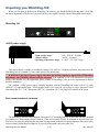
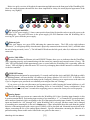
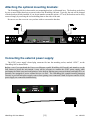
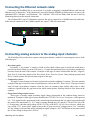
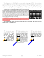
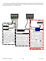
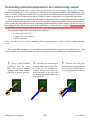
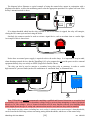
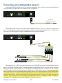
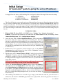
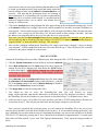
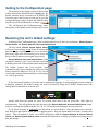
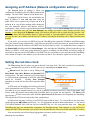
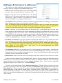
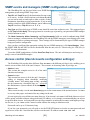
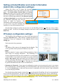
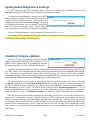
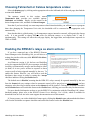
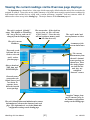
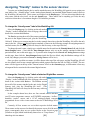
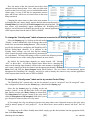
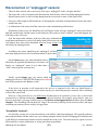
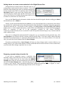
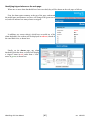
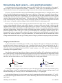
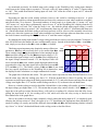
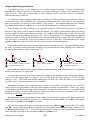
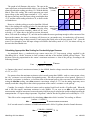
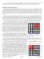
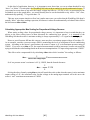
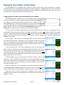
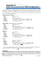
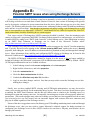


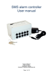
![[Unlocked] SC-2042](http://vs1.manualzilla.com/store/data/005660029_1-1367986a5e7a7fe673239a9957384234-150x150.png)