1
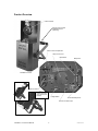
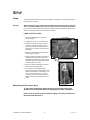
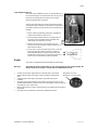
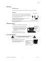
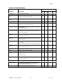
Intimidator™ 2.0 HTI USER MANUAL Intimidator™ 2.0 HTI Chauvet, 3000 N 29th Ct, Hollywood, FL 33020 U.S.A (800) 762-1084 – (954) 929-1115 FAX (954) 929-5560 www.chauvetlighting.com 2006-07-14/15:32 TABLE OF CONTENT TABLE OF CONTENT ...................................................................................................................................................... 2 BEFORE YOU BEGIN ...................................................................................................................................................... 3 WHAT IS INCLUDED................................................................................................................................................................................ 3 UNPACKING INSTRUCTIONS .................................................................................................................................................................... 3 AC POWER .......................................................................................................................................................................................... 3 SAFETY INSTRUCTIONS .......................................................................................................................................................................... 3 INTRODUCTION............................................................................................................................................................... 4 FEATURES ............................................................................................................................................................................................ 4 DMX CHANNEL SUMMARY ..................................................................................................................................................................... 4 PRODUCT OVERVIEW ............................................................................................................................................................................ 5 SETUP .............................................................................................................................................................................. 6 LAMP ................................................................................................................................................................................................... 6 Lamp installation ................................................................................................................................................................................................ 6 POWER ................................................................................................................................................................................................ 6 MOUNTING ........................................................................................................................................................................................... 8 Orientation.......................................................................................................................................................................................................... 8 Rigging ............................................................................................................................................................................................................... 8 MANUAL FOCUSING ............................................................................................................................................................................... 8 FUSE REPLACEMENT ............................................................................................................................................................................. 8 OPERATING INSTRUCTIONS.......................................................................................................................................... 9 OPERATING MODES .............................................................................................................................................................................. 9 Stand Alone.............................................................................................................................................................. 9 Master/Slave ............................................................................................................................................................ 9 Master/Slave settings......................................................................................................................................................................................... 9 DMX Mode ............................................................................................................................................................... 9 Setting the starting address ............................................................................................................................................................................... 9 CA-9 EASY CONTROLLER (OPTIONAL) ................................................................................................................................................. 11 APPENDIX...................................................................................................................................................................... 12 DMX PRIMER ..................................................................................................................................................................................... 12 Fixture Linking.................................................................................................................................................................................................. 12 DMX CHANNEL VALUES ...................................................................................................................................................................... 13 MAINTENANCE .................................................................................................................................................................................... 14 RETURNS PROCEDURE ........................................................................................................................................................................ 14 CLAIMS .............................................................................................................................................................................................. 14 GENERAL TROUBLESHOOTING.............................................................................................................................................................. 15 TECHNICAL SPECIFICATIONS ................................................................................................................................................................ 16 Intimidator™ 2.0 HTI User Manual 2 2006-07-14/15:32 BEFORE YOU BEGIN What is included 1 x Intimidator™ 2.0 HTI Intelligent Mirror Scanner Power cord with plug HTI-150W lamp Warranty Card Unpacking Instructions Immediately upon receiving a fixture, carefully unpack the carton, check the contents to ensure that all parts are present, and have been received in good condition. Notify the shipper immediately and retain packing material for inspection if any parts appear damaged from shipping or the carton itself shows signs of mishandling. Save the carton and all packing materials. In the event that a fixture must be returned to the factory, it is important that the fixture be returned in the original factory box and packing. AC Power To determine the power requirements for a particular fixture, see the label affixed to the back plate of the fixture or refer to the fixture’s specifications chart. A fixture’s listed current rating is its average current draw under normal conditions. All fixtures must be powered directly off a switched circuit and cannot be run off a rheostat (variable resistor) or dimmer circuit, even if the rheostat or dimmer channel is used solely for a 0% to 100% switch. Before applying power to a AC Voltage Switch fixture, check that the source voltage matches the fixture’s requirement. Check the fixture or device carefully to make sure that if a voltage selection switch exists that it is set to the correct line voltage you will use. Warning! Verify that the power select switch on your unit matches the line voltage applied. All fixtures must be connected to circuits with a suitable Earth Ground. Safety Instructions Please read these instructions carefully, which includes important information about the installation, usage and maintenance? Please keep this User Guide for future consultation. If you sell the unit to another user, be sure that they also receive this instruction booklet. Always make sure that you are connecting to the proper voltage and that the line voltage you are connecting to is not higher than that stated on decal or rear panel of the fixture. This product is intended for indoor use only! To prevent risk of fire or shock, do not expose fixture to rain or moisture. Make sure there are no flammable materials close to the unit while operating. The unit must be installed in a location with adequate ventilation, at least 50cm from adjacent surfaces. Be sure that no ventilation slots are blocked. Always disconnect from power source before servicing or replacing lamp or fuse and be sure to replace with same lamp source. Caution! Secure fixture to fastening device using a safety chain. Never carry the fixture solely by its head. Use its carrying handles. Maximum ambient temperature is Ta: 40°. Do not operate fixture at temperatures higher than this. In the event of serious operating problem, stop using the unit immediately. Never try to repair the unit by yourself. Repairs carried out by unskilled people can lead to damage or malfunction. Please contact the nearest authorized technical assistance center. Always use the same type spare parts. Don’t connect the device to a dimmer pack. Make sure power cord is never crimped or damaged. Never disconnect power cord by pulling or tugging on the cord. Avoid direct eye exposure to lamp while it is on. There are no user serviceable parts inside the unit. Do not open the housing or attempt any repairs yourself. In the unlikely event your unit may require service, please contact CHAUVET. Intimidator™ 2.0 HTI User Manual 3 2006-07-14/15:32 INTRODUCTION Features Intimidator™ 2.0 HTI Control Features 5 channel DMX Intelligent Scanner Strobing Gobo Wheel - 14 gobos plus open - 12 metal, 2 glass - Gobo Bounce™ Color Wheel - 11 colors plus open - (include UV purple) plus white Pan: 180° in .5 sec. Tilt: 90° in .3 sec. Features Built in beat activated and automatic programs (stand-alone) Double bracket yoke doubles as floor stand Bulb saver cuts off after 10 seconds Surface coated mirror for optimum luminosity Automatically enters stand-alone when no DMX signal is present Linkable via Master/Slave Micro-stepping motors Thermal switch Fan cooled Options Wired remote controllers: CA-9 Easy Controller DMX Channel Summary CHANNEL FUNCTION 1 Strobe 2 Gobo 3 Color 4 Pan 5 Tilt Intimidator™ 2.0 HTI User Manual 4 2006-07-14/15:32 Product Overview Mirror Scanner Hanging Yoke, double bracketed for floor positioning Power & Fuse compartment Lamp access cover Dipswitches Microphone Intimidator™ 2.0 HTI DMX connectors Double bracketed yoke used for floor positions. Voltage Switch Sound Sensitivity Knob Remote Controller Input Intimidator™ 2.0 HTI User Manual 5 2006-07-14/15:32 SETUP Lamp You will need to install a lamp prior to the initial operation of the fixture. An HTI-150W high intensity discharge lamp is included. Warning! When replacing the lamp, please wait 15 minutes after powering down to allow the unit to cool down! Always disconnect from main power prior to lamp replacement. Do not touch the envelope (glass area) of the bulb with bare hands. If this happens, clean the lamp with alcohol and wipe it with a lint free cloth before installation. L AM P I N ST ALL AT I O N 1. Remove screws labeled (S1) and pull out lamp socket plate. 2. If replacing the lamp, remove old lamp first. Lamp Installation S2 3. Holding the new lamp by its base, align the pins on the lamp with the small hole in the socket and insert the lamp squarely until the retaining clips on the lamp socket secure the lamp tightly. 4. Clean the glass/envelope of the bulb with an alcohol wipe or equivalent. 5. Holding the lamp socket plate, insert the tip of the lamp into the fixture with extreme care. Navigate the lamp all the way until it reaches the reflector and the lamp base plate touches the bottom plate of the fixture. 6. Align the screw holes and fasten the screws back onto the lamp socket plate. S1 Remove both thumbscrews Lamp exposed 7. Turn the fixture on and adjust the lamp alignment screws (S2) until the brightest most even area of the beam is in the center of your spot. It may be necessary for you to use a controller in order to command the fixture to display a white beam on a flat surface with no colors. Maximizing the life of your lamp To ensure the longest and most efficient use of the lamp always wait between 10 and 15 minutes before re-applying power after a shutdown. Failure to do so could result in premature aging of the lamp and failure to the electronics that drive it. Intimidator™ 2.0 HTI User Manual 6 2006-07-14/15:32 Setup Lamp Alignment How-To Often, after a new installation of a lamp, you will find that there is an uneven field of light or what is referred to as a hot spot. This is due to the most intense point of the lamp source not being positioned optimally within the reflector. There are three lamp alignment screws S2 provided at the base of the projector head. Turning these screws allow you to optimize the projection quality of the spot as well as the overall intensity of the beam. S2 1. Project a white spot against any flat surface. Preferably the surface should be white or pastel in color. 2. Turning the lamp alignment screws, try to position the hot spot in the center of the beam as best as possible. This could require many attempts on your part. S2 3. Once the hot spot is in the center of the spot, do your best to turn all screws equally as to affect movement up or down within the reflector. Lamp Alignment Screws 4. As you move in and out of optimum lamp focus, you will see the hot spot either gets wider or narrower. The goal is to either totally diminish the hot spot by having it widen and spread across the entire spot or moving the hot spot so that it covers as much of the beam spot area as possible. Power Your product is equipped with switch-selectable AC power setting. Warning! Verify that the power select switch on your unit matches the line voltage applied. All fixtures must be connected to circuits with a suitable Earth Ground. Slide switch up or down To determine the power requirements for a particular fixture, see the label depending on your line voltage. affixed to the back plate of the fixture or refer to the fixture’s specifications chart. A fixture’s listed current rating is its average current draw under normal conditions. All fixtures must be powered directly off a switched circuit and cannot be run off a rheostat (variable resistor) or dimmer circuit, even if the rheostat or dimmer channel is used solely for a 0% to 100% switch. Before applying power to a fixture, check that the source voltage matches the fixture’s requirement. All fixtures must be connected to circuits with a suitable Earth Ground. Intimidator™ 2.0 HTI User Manual 7 2006-07-14/15:32 Setup Mounting O RI E NT AT IO N This fixture may be mounted in any position provided there is adequate room for ventilation. RIG G ING Hanging Clamp It is important never to obstruct the fan or vents pathway. Mount the fixture using, a suitable “C” or “O” type clamp. Adjust the angle of the fixture by loosening both knobs and tilting the fixture. After finding the desired position, retighten both knobs. o o o When selecting installation location, take into consideration lamp replacement access and routine maintenance. Note! Clamp is sold separately. Safety cables should always be used. Never mount in places where the fixture will be exposed to rain, high humidity, extreme temperature changes or restricted ventilation. Manual Focusing To adjust the focus, please follow the instructions below. 1) 2) If operating in stand alone mode, turn the music down so that the unit temporarily stops any activity. In DMX control mode, create a static scene with any gobo of your choice pointed to a flat surface, ideally at a half-way point of the fixtures total coverage area. Rotate lens gun clockwise and counterclockwise to achieve desired focus. Rotate the lens gun either clockwise or counterclockwise until the spot is defined by a hard edge. Fuse Replacement Disconnect the power cord before replacing a fuse and always replace with the same type fuse. With a flat head screwdriver wedge the fuse holder out of its housing. Remove the damaged fuse from its holder and replace with exact same type fuse. Insert the fuse holder back in its place and reconnect power. Intimidator™ 2.0 HTI User Manual 8 The fuse is located inside this compartment. Remove using a flat head screwdriver. 2006-07-14/15:32 OPERATING INSTRUCTIONS Operating Modes A stand-alone mode will listen to sound and run through its diverse range of built in programs. Master/Slave mode will allow the command of up to as many units you want in a synchronized light show to the sound. DMX control mode will provide the greatest flexibility and creativity. Each fixture trait can be controlled individually using any universal DMX-512 controller. Stand Alone The Stand Alone mode is activated automatically when the fixture is absent of DMX signal or a controller is not connected. The fixture will run through its built in programs as it listens to the sound. Master/Slave The Master/Slave mode will allow you to link up to as many units you want in a daisy chain fashion. In this mode, the first unit in the daisy chain will automatically command all other units following. Connecting this fixture for (Master/Slave) operation does not require any menu or setting selections. Simply connect each unit in a daisy like fashion using qualified 3 pin DMX cables as described below. M AST E R/ S L AV E S ET T ING S 1) Connect the (male) 3 pin connector side of the DMX cable to the output (female) 3 pin connector of the first fixture. 2) Connect the end of the cable coming from the first fixture which will have a (female) 3 pin connector to the input connector of the next fixture consisting of a (male) 3 pin connector. Then, proceed to connect from the output as stated above to the input of the following fixture and so on as illustrated below. Daisy Chain Connection Optional Controller Note! For additional information on linking fixtures read under section “DMX Primer” DMX Mode Operating in a DMX Control mode environment gives the user the greatest flexibility when it comes to customizing or creating a show. In this mode you will be able to control each individual trait of the fixture independently. S ET T ING T H E ST ART ING AD D R E SS This DMX mode enables the use of a universal DMX controller device. Each fixture requires a "start address" from 1 to 511. A fixture requiring one or more channels for control begins to read the data on the channel indicated by the start address. For example, a fixture that occupies or uses 6 channels of DMX and was addressed to start on DMX channel 100, would read data from channels: 100, 101, 102, 103, 104, and 105. Choose start addresses so that the channels used do not overlap and notate the start address selected for future reference. Intimidator™ 2.0 HTI User Manual 9 2006-07-14/15:32 Operating Instructions If this is your first time addressing a fixture using the DMX-512 control protocol than I suggest jumping to the Appendix Section and read the heading “DMX Primer”. It contains very useful information that will help you understand its use. Set the start address using the group of DIP switches located usually on bottom of the fixture. Each dip switch has an associated value. Adding the value of each switch in the ON position will provide the start address. Determining which switches to toggle ON given a specific start address can be accomplished in the following manner. By subtracting the largest switch value possible from the selected start address which does not cause a negative number. EXAMPLE STARTING ADDRESS 10 OPTION Address 10 9 256 7 64 8 Pin # 4 Pin # 2 Total =8 =2 = 10 6 5 4 3 2 1 4 2 1 256 7 64 6 5 4 3 2 1 10 128 32 16 8 4 2 1 ON OFF 233 – (128) = 105, Turn ON Dip #8 105 – (64) = 41, Turn ON Dip # 7 41 – (32) = 9, Turn ON Dip # 6 9 – (8) = 1, Turn ON Dip # 4 1 – (1) = 0, Turn ON Dip # 1 You will most likely use the first available number which maybe number 1. This number was selected for example purposes. Intimidator™ 2.0 HTI User Manual 8 ON OFF = 16 =8 = 24 Address 233 16 9 8 Resolving address using simple math. 32 10 OPTION Address 24 Pin # 5 Pin # 4 Total 128 DIP SWITCH (DMX VALUE) 1 2 3 4 5 6 7 8 9 10 1 2 4 8 16 32 64 128 256 2006-07-14/15:32 CA-9 Easy Controller (Optional) STAND BY MODE FUNCTION Pan & Tilt is sound activated but Gobo and Color wheel are static and controlled by the Function button. LED ON: Slow Mode Tap the Function button to step through the 11 colors then once more to step to the next gobo. The unit’s movement Pan & Tilt and Gobo/Color is sound activated. BLACKOUT Press and hold the Function button to achieve the following results. LED OFF: Fast Mode Intimidator™ 2.0 HTI User Manual . a. Strobe in different colors and gobos b. Synchronous strobe in white c. Two-light strobe in white color 11 2006-07-14/15:32 APPENDIX DMX Primer There are 512 channels in a DMX-512 connection. Channels may be assigned in any manner. A fixture capable of receiving DMX 512 will require one or a number of sequential channels. The user must assign a starting address on the fixture that indicates the first channel reserved in the controller. There are many different types of DMX controllable fixtures and they all may vary in the total number of channels required. Choosing a start address should be planned in advance. Channels should never overlap. If they do, this will result in erratic operation of the fixtures whose starting address is set incorrectly. You can however, control multiple fixtures of the same type using the same starting address as long as the intended result is that of unison movement or operation. In other words, the fixtures will be slaved together and all respond exactly the same. DMX fixtures are designed to receive data through a serial Daisy Chain. A Daisy Chain connection is where the DATA OUT of one fixture connects to the DATA IN of the next fixture. The order in which the fixtures are connected is not important and has no effect on how a controller communicates to each fixture. Use an order that provides for the easiest and most direct cabling. Connect fixtures using shielded two conductor twisted pair cable with three pin XLR male to female connectors. The shield connection is pin 1, while pin 2 is Data Negative (S-) and pin 3 is Data positive (S+). CHAUVET carries 3-pin XLR DMX compliant cables, DMX-10 (33’), DMX-4.5 (15’) and DMX-1.5 (5’) FI XT UR E LI NK ING Figure 1 - DMX connector configuration 1 3 2 COMMON INPUT Note! 1 3 2 1 3 2 DMX + Resistance 120 ohm 1/4w between pin 2 (DMX -) and pin 3 (DMX +) of the last fixture. OUTPUT DMX - Termination reduces signal errors and to avoid signal transmission problems and interference, it is always advisable to connect a DMX signal terminator. If you use a controller with a 5 pin DMX output connector, you will need to use a 5 pin to 3 pin adapter. CHAUVET Model No: DMX5M. The chart below details a proper cable conversion: 3 PIN TO 5 PIN CONVERSION CHART CONDUCTOR 3 Pin Female (output) 5 Pin Male (Input) GROUND/SHIELD Pin 1 Pin 1 DATA ( - )SIGNAL Pin 2 Pin 2 DATA ( + ) SIGNAL Pin 3 Pin 3 DO NOT USE Do not use DO NOT USE Do not use Intimidator™ 2.0 HTI User Manual 12 2006-07-14/15:32 Appendix DMX Channel Values Channel Value 1 000 015 016 091 092 135 136 195 196 255 Strobe Gobo Stopped Adjacent gobo strobe: Slow > Fast Adjacent color strobe: Slow > Fast Adjacent color and gobo strobe: Slow > Fast Gobo Bounce™: Slow > Fast 2 000 007 008 015 016 023 024 031 032 039 040 047 048 055 056 063 064 071 072 079 080 087 088 095 096 103 104 111 112 119 120 127 128 255 Gobo Blackout Open Gobo 1 Gobo 2 Gobo 3 Gobo 4 Gobo 5 Gobo 6 Gobo 7 Gobo 8 Gobo 9 Gobo 10 Gobo 11 Gobo 12 Gobo 13 Gobo 14 Gobo Spin: Slow > Fast 3 000 010 011 012 022 023 033 034 044 045 055 065 066 076 077 087 088 098 099 109 110 120 121 127 128 255 Color Open/White Red Dark Blue Yellow Green Pink UV Cyan Orange Magenta Tri-Color (Red-White-Blue) Quad-Color Color Spin: Slow > Fast 4 000 255 Pan 0° - 180° 5 000 255 Tilt 0° - 90° Intimidator™ 2.0 HTI User Manual Function 13 2006-07-14/15:32 Appendix Maintenance To maintain optimum performance and minimize wear fixtures should be cleaned frequently. Usage and environment are contributing factors in determining frequency. As a general rule, fixtures should be cleaned at least twice a month. Dust build up reduces light output performance and can cause overheating. This can lead to reduced lamp life and increased mechanical wear. Be sure to power off fixture before conducting maintenance. Unplug fixture from power. Use a vacuum or air compressor and a soft brush to remove dust collected on external vents and internal components. Clean all glass when the fixture is cold with a mild solution of glass cleaner or Isopropyl Alcohol and a soft lint free cotton cloth or lens tissue. Apply solution to the cloth or tissue and drag dirt and grime to the outside of the lens. Gently polish optical surfaces until they are free of haze and lint. Do not to touch the lamp glass when cleaning fixture. Oil and dirt can cause damage and premature aging of the lamp. In the event that the lamp is touched or becomes dirty, clean the lamps with an alcohol wipe. The cleaning of internal and external optical lenses and/or mirrors must be carried out periodically to optimize light output. Cleaning frequency depends on the environment in which the fixture operates: damp, smoky or particularly dirty surrounding can cause greater accumulation of dirt on the unit’s optics. Clean with soft cloth using normal glass cleaning fluid. - Always dry the parts carefully. - Clean the external optics at least every 20 days. Clean the internal optics at least every 30/60 days. Returns Procedure Returned merchandise must be sent prepaid and in the original packing, call tags will not be issued. Package must be clearly labeled with a Return Merchandise Authorization Number (RA #). Products returned without an RA # will be refused. Call CHAUVET and request RA # prior to shipping the fixture. Be prepared to provide the model number, serial number and a brief description of the cause for the return. Be sure to properly pack fixture, any shipping damage resulting from inadequate packaging is the customer’s responsibility. CHAUVET reserves the right to use its own discretion to repair or replace product(s). As a suggestion, proper UPS packing or double-boxing is always a safe method to use. Claims Damage incurred in shipping is the responsibility of the shipper; therefore the damage must be reported to the carrier upon receipt of merchandise. It is the customer's responsibility to notify and submit claims with the shipper in the event that a fixture is damaged due to shipping. Any other claim for items such as missing component/part, damage not related to shipping, and concealed damage, must be made within seven (7) days of receiving merchandise. Intimidator™ 2.0 HTI User Manual 14 2006-07-14/15:32 Appendix General Troubleshooting Applies to Symptom Solution(s) Auto shut off Check fan thermal switch reset Beam is very dim or not bright Clean optical system or replace lamp Breaker/Fuse keeps blowing Check total load placed on device Chase is too slow Check users manual for speed adjustment Device has no power Check for power on Mains. Lights Foggers & Snow Controllers Dimmers & Chaser Check 220/110v switch for proper setting Check device’s fuse. (internal and/or external) Fixture is not responding Check DMX Dip switch settings for correct addressing Check DMX cables Check polarity switch settings Fixture is on but there is no movement to the audio Make sure you have the correct audio mode on the control switches. If audio provided via ¼” jack, make sure a live audio signal exists Adjust sound sensitivity knob Lamps cuts off sporadically Possible bad lamp or fixture is overheating. Light will not come on after power failure Some discharge lamps require a cooling off period before the electronics in the fixture can kick start it again, wait 5 to 10 minutes before powering up Loss of signal Use only DMX cables Lamp may be at end of its life. Install terminator Note: Keep DMX cables separated from power cables or black lights. Motor movements are jerky or jumpy Possible bad motor driver or sensors Moves slow Check 220/110v switch for proper setting No flash Re-install bulb, may have shifted in shipping No light output Check slip ring & brushes for contact Check polarity switch on controller Install bulb Call service technician Relay will not work Check reset switch Check cable connections Remote does not work Make sure connector is firmly connected to device Stand alone mode All CHAUVET lighting fixtures featuring stand-alone functions do not require additional settings, simply power the fixture and it will automatically enter into this mode Unit wobbles when rotating Check for damages possibly incurred during shipping Intimidator™ 2.0 HTI User Manual 15 2006-07-14/15:32 Appendix Technical Specifications WEIGHT & DIMENSIONS Length..................................................................................................................... 584.2 mm (23.0 in) Width....................................................................................................................... 266.7 mm (10.5 in) Height ..................................................................................................................... 171.5 mm (6.75 in) Weight.....................................................................................................................9.56 Kg (21.08 lbs) POWER Switch-selectable power setting ..................................................................115V 60 Hz or 230V 50 Hz AC input .......................................................................................3-prong IEC 60320 C14 male socket Current draw ................................................................. (peak 168W @ 120V), (inrush 360W @ 120V) European version ...................................................................................................... 230V/240V 50 Hz LAMP HTI150 ............................................................................................................... 150W 6500°K 750hrs PHOTOMETRICS Illuminance........................................................................................ (1,800fc or 19,368lux) @ 1 meter Beam Angle .................................................................................................................................... 12° THERMAL Maximum ambient temperature ......................................................................................... 40° (104° F) FUSE Main ......................................................................................................... 20mm Glass 6.3A Fast Blow CONTROL & PROGRAMMING Data input ............................................................................................. locking 3-pin XLR male socket Data output ........................................................................................ locking 3-pin XLR female socket Data pin configuration ............................................................................pin 1 shield, pin 2 (-), pin 3 (+) Protocols.....................................................................................................................DMX-512 USITT DMX Channels ....................................................................................................................................5 ORDERING INFORMATION Intimidator™ 2.0 HTI ................................................................................................Intimidator 2.0 HTI CA-9 Easy Controller.....................................................................................................................CA-9 Intimidator™ 2.0 HTI User Manual 16 2006-07-14/15:32