1
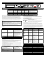
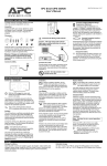
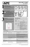
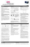
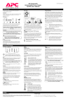
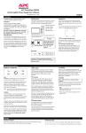
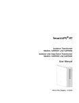
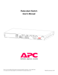
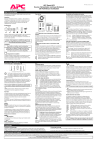
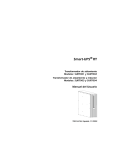
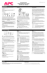
Note!
When managed by PowerChute UPS software the Redundant Switch should be
used with Servers running Windows NT.
Smart-UPS Redundant Switch User’s
Manual
English
990-0275A, Revision 2 5/98
Initial Start-Up
To obtain warranty coverage, please fill out and
return the warranty registration card now.
Inspection
Inspect the Redundant Switch upon receipt. Notify
the carrier and dealer if there is damage. The
packaging is recyclable; save it for reuse or dispose
of it properly.
Placement
Rear View
Model
SU041
CAUTION:
L
UNINTERRUPTIBLE
RISK OF ELECTRIC SHOCK. DO NOT REMOVE TOP COVER. NO USER
POWER SUPPLY SERVICEABLE PARTS INSIDE. REFER SERVICING TO QUALIFIED SERVICE PERSONNEL.
®
ACCESSORY
FOR USE IN A CONTROLLED ENVIRONMENT. REFER TO MANUAL FOR ENVIRONMENTAL CONDITIONS.
I S T E D 4L2RC6 23 9 3 8 MADE IN USA
THIS EQUIPMENT USES TWO (2) AC SOURCES
E95463
MODEL :
S/N:
THIS DEVICE COMPLIES WITH PART 15 OF THE FCC RULES.
OPERATION IS SUBJECT TO THE FOLLOWING TWO CONDITIONS:
Voltage
Source
Load
120 V
5-15
5-15
1.THIS DEVICE MAY NOT CAUSE HARMFUL INTERFERENCE AND
2.THIS DEVICE MUST ACCEPT ANY INTERFERENCE RECEIVED
THAT MAY CAUSE UNDESIRED OPERATION.
•Plug the power cords attached to the Redundant
Switch into each UPS.
•Follow the UPS installation instructions in the
Smart-UPS Quick Reference Guide to install the
UPS.
•Both UPS units should be the same sine-wave
model.
•Install the 940-1000A communication cable(s)
between each UPS and the Redundant Switch.
Make sure that the communications cable for the
preferred UPS, UPS-A, and the power cord for
UPS-A are connected to the same UPS.
3. Turn on all connected
equipment
2. Connect Equipment
Install the Redundant Switch in a protected area that
is free of excessive dust and has adequate air flow.
Do not operate the Redundant Switch where the
temperature and humidity are outside the specified
limits.
Warning: Changes or modifications to this unit
not expressly approved by the party responsible
for compliance could void the warranty.
Installation
This Redundant Switch is equipped with a
SmartSlot for additional manageability. See the
APC Website (www.apcc.com) for information on
plug-in accessories.
•Do not power laser
printers through the
Redundant Switch.
Use your server’s power cords to connect to the
Redundant Switch.
Note: If you have more than two power cords to
connect, use a power strip. APC recommends
that you do not use a surge protective power strip.
•Install the PowerChute® plus communication
cable between the Redundant Switch’s server port
and the server’s serial port.
1. Install Redundant Switch
Press the ON switch of UPS-A to turn on your
Redundant Switch and UPS-B. This will power-up
connected equipment.
Note: To test whether the cabling is correct, shut
off one UPS using its OFF button. If it turns back
on, the cabling is correct. If not, swap the two
UPS communication cables.
Storage
Store Redundant Switch covered and upright in a
cool, dry location. Remove any accessories in the
accessory slot and disconnect any cables connected
to the server interface port.
•Before plugging in the unit, install
any compatible SmartSlot accessory.
Refer to the Release Notes found in
the CD included with the Redundant
Switch for detailed information.
Follow the installation instructions
that come with the accessory.
Supported Configurations
Two connection configurations are supported for Redundant Switch. They are illustrated below.
Note: Redundant Switch does not support communications with accessories installed in the UPS. Install the accessory you need in Redundant Switch.
Better Configuration: Smart-UPS Redundant Switch with two Smart-UPS units connected to one AC line.
This configuration is the minimal acceptable, since both UPS units depend on one facility power source.
Note: Both UPS units should be the same sine-wave model.
Best Configuration: Smart-UPS Redundant Switch with two Smart-UPS units connected to two separate AC lines.
This configuration is better than the previous, since each UPS unit receives power from a separate facility power source.
Note: Both UPS units should be the same sine-wave model.
PowerChute® plus Configuration Procedure
1. Install PowerChute® plus following the instructions in the enclosed Software
Installation Instruction Sheet.
2. Start up PowerChute® plus. By default, communication is to UPS-A.
3. Configure UPS-A according to your requirements.
4. Set the UPSID to UPS_A.
5. At the Redundant Switch front panel, set the Source Preference to Source B.
6. Restart the computer on which PowerChute® plus is installed.
7. Restart PowerChute® plus. Communication is to UPS-B.
8. Configure UPS-B to be identical to UPS-A except
• UPS-B should be set to not perform self-tests.
• Set the UPSID to UPS_B.
9. At the Redundant Switch front panel, set the Source Preference to Source A.
10. Restart the computer on which PowerChute® plus is installed.
11. Restart PowerChute® plus. Communication is now to UPS-A.
Notes
High availability is the condition in which both UPSs are available to supply
AC power. Standard availability is when only one UPS is fully available for
back up power. A loss of power to either input of Redundant Switch results in a
“self test failed: invalid test” message from PowerChute which indicates a
change from high availability to standard availability.
If UPS-A fails, Redundant Switch senses this and transfers the load’s AC
power input and PowerChute communication to UPS-B. During a transfer
from one source to the other Redundant Switch is designed to interrupt
communications with PowerChute® plus for three seconds (forcing a “lost
comm” event through PowerChute) . PowerChute® plus then attempts to reestablish communications (with the available UPS). You are notified that the
server AC power has gone from high availability to standard availability when
PowerChute® plus records the following message:
Alternate UPS engaged or lost comm. Examine Redundant Switch for details.
When the selected UPS self-tests, Redundant Switch switches to the other UPS,
causing a self-test of that UPS, then switches back.
Operating Instructions
Front View
Status
To UPS B
Status Select
Select
Level
R
T
N
I +
N 2
4
AC Source
B
A
To UPS A
To Server
Function
Bright
Source selected
EPO
Dim
Emergency
Power Off
Off
Source OK, but not selected
Source not OK
R e d u n d a n t Sw i t c h
Note: Only the Factory Default settings shown below should be used. Check that these are the current settings for your unit. Additional setting are for future
upgrades.
Function
Source A Sensitivity
Factory
Default
Reduced
User Selectable Choices
LED Bright LED Dim
LED Off
Normal
Reduced
Low
Source B Sensitivity
Reduced
Normal
Reduced
Low
Source Preference
Source A Xfer Voltage
Source B Xfer Voltage
Source A
Medium
Medium
Source A
Narrow
Narrow
Source B
Medium
Medium
None
Wide
Wide
Emergency Power Off
The UPS may be switched off by a remotely operated Emergency Power Off (EPO) control.
Such a configuration is common in computer rooms and laboratories where, for safety
reasons, power to the loads must be disconnected. To connect Redundant Switch and its
attached Smart-UPS to your emergency power off system, use the EPO connector. Use a
normally-open contact to connect the +24 terminal to the IN terminal. A certified electrician
can wire the external blue four-pin female connector to the emergency power off system. If
this is done, and the emergency power off system is activated, neither UPS will go onbattery.
Cautions
• The EPO interface is a Safety Extra Low Voltage (SELV) circuit and may be
connected only to other SELV circuits.
• The EPO interface is designed to monitor circuits that have no determined voltage
potential. Such closure circuits may be provided by a switch or relay properly
isolated from the utility. Connection of the EPO interface to any circuit other than
a closure type circuit may cause damage to the Redundant Switch.
Front Panel User Programming
User programmable settings are accessible using controls located on the Redundant Switch
front panel.
Troubleshooting Redundant Switch
Problem
Redundant Switch will not
turn on.
Possible Cause
Very low or no utility voltage.
Server cannot communicate
with attached UPS through
Redundant Switch.
Communications cabling
problem or internal
Redundant Switch fault.
Description
Sets transfer sensitivity to line
conditions
Sets transfer sensitivity to line
conditions
Selects the preferred AC source
Sets the transfer voltage window
Sets the transfer voltage window
Function Select LED Indicator
The three green Function Select LEDs indicate which user programmable parameter is
selected for status display or modification. Use the left Select button to cycle through the
five user configurable items listed above.
Function Status LED Indicator
The green Function Status LED indicates the state of the selected user programmable
function. Use the right Select button to cycle among the choices.
AC Source LED Indicator
The green on-line LED indicates the line quality and select status of
each source: Bright = source selected; Dim = source okay, not
selected; Off = source not okay; 1 second flashing of 1 LED, other
LED off = both AC sources are out of tolerance.
Source Sensitivity
Generators connected to the Redundant Switch are not supported. However, Redundant
Switch detects line voltage distortions such as spikes, notches, dips, and swells, as well as
the distortions inexpensive fuel-powered generators typically produce. By default, the UPS
reacts to distortions by transferring to on-battery operation to protect the loads. Where power
quality is poor, Redundant Switch will change from the primary source UPS to the alternate
UPS. If the loads can operate normally under such conditions, battery capacity and service
life may be conserved by reducing the sensitivity of the UPSs, and setting the Source A and
Source B Sensitivity to Low on the Redundant Switch.
Troubleshooting the High Availability System
Corrective Action
Check the AC power supply to the
Redundant Switch with a table lamp. If
very dim, have the utility voltage checked.
Check that AC plugs are properly
connected between Redundant Switch and
the UPSs.
Check the three communication cable
connections. If they are tight and there is
still no communication, connect the server
directly to a UPS. If there is now
communication, there is an internal
Redundant Switch fault. In any case,
Contact APC customer service (see
Service section).
See Service section, below.
Problem/Severity
(1=low, 4=high)
UPS-B
communications
problem.
Severity = 1
High Availability
System Response
Load not interrupted;
PowerChute plus
self-test reports error.
UPS-A
communications
problem.
Severity = 2
Load not interrupted;
Redundant Switch
checks
communications
continuously.
UPS-B loses ability to
deliver load if
engaged.
Severity = 3
Load not interrupted;
Redundant Switch
and PowerChute plus
monitor
continuously.
If the Redundant Switch requires service do not return it to the dealer!
Follow these steps:
1. Use the Troubleshooting section to eliminate common problems.
2. If the problem persists, call customer service or visit the APC Internet Website (www.apcc.com).
•Note the model number of the Redundant Switch, the serial number, and the date purchased. A technician
will ask you to describe the problem and try to solve it over the phone, if possible. If this is not possible the
technician will issue a Return Merchandise Authorization Number (RMA#).
•If the Redundant Switch is under warranty, repairs are free. If not, there is a repair charge.
3. Pack the Redundant Switch in its original packaging. If the original packing is not available, ask customer
service about obtaining a new set.
•Pack the Redundant Switch properly to avoid damage in transit. Never use Styrofoam beads for packaging.
Damage sustained in transit is not covered under warranty.
•Include a letter with your name, RMA#, address, copy of the sales receipt, description of the trouble, your
daytime phone number, and a check (if necessary).
4. Mark the RMA# on the outside of the package.
5. Return the Redundant Switch by insured, prepaid carrier to the address given to you by Customer Service.
UPS-A drops output
voltage
Severity = 4
Load not interrupted;
Redundant Switch
checks continuously.
Redundant Switch
engages UPS-B for
load delivery and
communications
proactively.
All Redundant Switch LEDs
Internal, automated self-test
are flashing.
failure: defective unit
For Computer Interface Port Specifications, see the APC Website (www.apcc.com).
Service
North & Latin America
Europe
APC
APC
132 Fairgrounds Road
Ballybritt Business Park
West Kingston, Rhode Island 02892 USA
Galway, Ireland 10800-702000
1-800-800-4APC/1-401-789-5735
353-91-702020
Internet: http://www.apcc.com
E-Mail:
E-Mail: apceurtech@apcc.com
North America: apctech@apcc.com
Latin America: apctchla@apcc.com
PowerChute plus
Response
Either:
•self-test at UPS failed,
invalid test
•unable to communicate
with UPS
PowerChute plus alerted
immediately.
Either:
•self-test at UPS failed,
invalid test
•unable to communicate
with UPS
PowerChute plus alerted
immediately.
Either:
•self-test at UPS failed,
invalid test
•unable to communicate
with UPS
PowerChute plus alerted
immediately.
Either:
•self-test at UPS failed,
invalid test
•alternate UPS engaged or
lost comm. View
Redundant Switch display
for details.
Corrective Action
Diagnose
communications path to
Redundant Switch.
Initiate Self-Test through
PowerChute plus.
Diagnose UPS-A.
Initiate Self-Test through
PowerChute plus.
Diagnose UPS-B.
Initiate Self-Test through
PowerChute plus.
Diagnose both UPS
units.
Specifications
Acceptable input voltage
Output voltage
Frequency limits (on-line operation)
Transfer time
Maximum load
Operating temperature
Storage temperature
Operating and storage relative humidity
Operating elevation
Storage elevation
Electromagnetic immunity
Audible noise in dBA @ 1 m (3 ft)
Size (H x W x D)
Weight - net (shipping)
Safety approvals
EMC verification
120 VAC: 0 - 165 VAC
120 VAC: 108 - 132 VAC (by default)
50 or 60 Hz, ±5%
6 ms typical
1400 VA 12 A
0 to +40 ºC (+32 to +104 ºF)
-15 to +45 ºC (+5 to +113 ºF)
0 to 95%, non-condensing
0 to +3,000 m (0 to +10,000 ft)
0 to +15,000 m (0 to +50,000 ft)
IEC 801-2, 801-3, 801-4
<45
4.45 x 43.2 x 19 cm (1.75 x 17.0 x 7.5 in.)
4.5 (6.8) kg/10 (15) lb.
Listed to UL 1778, certified to CSA 107.1
120 VAC: FCC Class A certified