Download EC type-examination certificate UK/0126/0157 Revision 1
Transcript
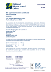
UK/0126/0157 MI-006 EC type-examination certificate UK/0126/0157 Revision 1 Issued by: The National Measurement Office Notified Body Number 0126 In accordance with the requirements of the Measuring Instruments (Non-Prescribed Instruments) Regulations 2006 (SI 2006/1257) and the Measuring Instruments (NonPrescribed Instruments) Regulations 2006 which implement, in the United Kingdom, Council Directive 2004/22/EC, this EC type-examination certificate has been issued to: Società Cooperativa Bilanciai a.r.l. Via S. Ferrari No 16 41011 Campogalliano Modena Italy In respect of a family of automatic checkweighing instruments designated the Selecta and having the following characteristics: Maximum capacity, Max Minimum capacity, Min Scale interval, e = Number of scale intervals Maximum belt speed Accuracy class ≤ 1200 g ≥ 50 g ≥ 0.2 g n ≤ 6000 ≤ 80 m/min XIII(1) ≤ 3000 g ≥ 50 g ≥ 0.5 g The necessary data (principal characteristics, alterations, securing, functioning etc) for identification purposes and conditions (when applicable) are set out in the descriptive annex to this certificate. This revision replaces previous versions of the certificate. Issue Date: Valid Until: Reference No: 12 May 2014 09 March 2024 TS0101/0022 Signatory: G Stones for Chief Executive National Measurement Office | Stanton Avenue | Teddington | TW11 0JZ | United Kingdom Tel +44 (0)20 8943 7272 | Fax +44 (0)20 8943 7270 | Web www.gov.uk/nmo NMO is an Executive Agency of the Department for Business Innovation & Skills 0135 MID Annex B Rev. 3 28 December 2012 Descriptive Annex 1 INTRODUCTION The instruments, designated the Selecta, are designed to operate as automatic checkweighers (Category X). The instruments comprise a cabinet, a pole-mounted display and user interface, conveyors, a weighing device and mechanical handling facilities. The instruments are designed to weigh packs dynamically. 2 FUNCTIONAL DESCRIPTION 2.1 Mechanical 2.1.1 The instrument (Figure 1) is constructed in stainless steel. The framework is a fabricated floor standing stainless steel frame on adjustable feet. On the frame are mounted the modular conveyor sections (in-feed, weigh platform, and out-feed). The conveyors type, number, size and shape are not restricted. The out-feed conveyor can be equipped with one of a number of reject devices, including a flipper, drop flap, ram or air blast. The in-feed or outfeed conveyors may be equipped with quality control system such as metal detectors or xrays. 2.1.2 The instrument is designed to be permanently installed and is fitted with a level indicator located on the weigh platform. 2.1.3 The control cabinet is located behind of the conveyors and houses the electrical hardware. 2.1.4 Weighing unit The weigh platform may be fabricated with steel or aluminium support. The weighing device comprises a strain gauge load cell located below the centre of the weigh conveyor. The load cell is as follows: Tedea load cell type 240 C3, Emax = 10 kg. 2.1.5 The system uses in-feed photocells to detect the arrival and passing of any packs (out-feed photocells are optional). The “Auto Zero” mode is active when there are no packs on the platform. Packs are weighed as they pass over the weigh conveyor, which runs continuously at the speed of the in-feed and out-feed conveyors. The weight signal is continually monitored to find the optimal point at which to take the final product weight. The analogue output is then sent to the load cell module to be digitised and processed. 2.2 Electrical 2.2.1 The control cabinet, located behind the conveyors, houses the electrical hardware. A door at the back of the cabinet allows access to the hardware: A/D converter board type 404801, main board with CPU type Geode LX 800, 500 MHz or equivalent, power supplies, motor drivers and appropriate relays. 2.2.2 A pole-mounted display and user interface unit (Figure 2) is located above the cabinet, and comprises an LCD touch screen. The interface allows viewing of weighing parameters and results, as well as access to the instrument’s various functions. 2/9 2.3 Devices The instrument has the following devices: Automatic zero setting device active during automatic operation (at least every 4 min 50 s) Semi-automatic zero-setting (≤ 4% max) Initial zero-setting (≤ 20% max) Pre-set tare device (subtractive) Static calibration, not accessible to the user Dynamic calibration, accessible to the user, recorded Dynamic setting Belt speed setting, accessible to the user Internal memory for storage of batch data Device acting upon significant faults Screen check at power-up High resolution mode (0.1e) for testing purposes, not accessible to the user: 3 TECHNICAL DATA 3.1 The family of instruments has the following technical characteristics. Maximum capacity (Max): Minimum capacity (Min): Scale interval (e =): Maximum number of scale intervals (n): Tare (T): Dynamic setting Belt speed: Climatic environment ≤ 1200 g ≥ 50 g ≥ 0.2 g n ≤ 6000 50 to 80 g: T ≤ 35 % Gross 50 to 80 g: T ≤ 35 % Gross 80 to 100 g: T ≤ 55 % Gross 80 to 100 g: T ≤ 55 % Gross 100 to 1200 g: T ≤ 70 % Gross 100 to 3000 g: T ≤ 70 % Gross 50 g to 300 g = ± 20% preset weight 300 g to 500 g = ± 10% preset weight 500 g to 1200 g = ± 20% preset weight 1200 g to 3000g = ± 240g preset weight ≤ 80 m/min 5 °C to +40 °C Non-condensing (closed) Electromagnetic environments Power supply Accuracy class 3.2 ≤ 3000 g ≥ 50 g ≥ 0.5 g E1 and E2 220-240 Va.c. 50 Hz XIII(1) Documentation and drawings Description User Manual Selecta dimensional drawings Selecta assembly drawings Selecta block diagram A/D converter schematics Main board / CPU schematics Drawing / Document number 81320469.pdf 07000647.pdf Selecta assembly drawings.xlsx Technical documentation.docx 404801M.pdf 404801A.pdf PCM-9375_User_Manual_ed2.pdf 404801A.pdf 3/9 Rev. 1.0 0 1 0 1.0 Power supply schematics Sealing 3.3 Software 3.3.1 Software identification 52050023_a01.pdf 52050035_a01.pdf 52050036_a01.pdf Sealing plan.docx 1 52050035_a01.pdf 52050036_a01.pdf The software is held on the CF card and comprises legally-relevant and non legally-relevant parts. The software identification shall be as follows: The A/D Converter software is designated “SCALE: 491064 x.x”, with x.x the release number that may change following minor modifications. The A/D converter software is fully legally relevant. The main board software comprises two parts. The legally relevant part is designated “LEGAL.OUT 4.x.x”, with x.x the release number that may change following minor modifications. The non-legally relevant part can be freely modified (currently designed VER.SW 6.1.0). The software identification can be accessed by pressing the bottom right icon, then “Ver.SW” (Figure 3). 3.3.2 Security The legally relevant part of the software can only be accessed by breaking the hardware seal preventing access to the CF card. Access via the user interface is prevented. The non legally-relevant software can be accessed via the user interface or communication ports, and can be freely modified. 4 PERIPHERAL DEVICES AND INTERFACES 4.1 Interfaces The instrument may have the any of following interface types: 4.2 Ethernet RS232 RS422 I/O board Peripheral devices The instrument may be connected to any peripheral device that has been issued with an Evaluatino of Parts certificate by a Notified Body responsible for Annex B (MI-006) under Directive 2004/22/EC in any Member State and bears the CE marking of conformity to the relevant directives; or A peripheral device without a test certificate may be connected under the following conditions: 4/9 it bears the CE marking for conformity to the EMC Directive; it is not capable of transmitting any data or instruction into the weighing instrument, other than to release a printout, checking for correct data transmission or validation; it prints weighing results and other data as received from the weighing instrument without any modification or further processing; and it complies with the applicable requirements of Paragraph 8.1 of Annex I. 5 APPROVAL CONDITIONS The following legends are durably and legibly marked on a rating plate located on the instrument (Figure 4): ‘CE’ marking Supplementary metrology marking Notified Body identification number Accuracy class Serial number Manufacturers mark or name Certificate number Model designation Max Min e= T=Climatic environment * Electromagnetic classification * Maximum speed / pack rate *: may be included in the documentation accompanying the instrument 6 LOCATION OF SEALS AND VERIFICATION MARKS 6.1 The ‘CE’ mark shall be impossible to remove without damaging it. The rating plate shall be impossible to remove without it being destroyed. The markings and inscriptions shall fulfil the requirements of Paragraph 9 of Annex I of the Directive 2004/22/EC. 6.2 Components that may not be dismantled or adjusted by the user (load cell, A/D board, CF card) must be secured. The seals shall bear a securing mark which may be either: a mark of the manufacturer and/or manufacturer’s representative, or an official mark of a verification officer. Access to the load cell connection, A/D board and CF card is prevented by the sealing measure described in Figure 5. 7 ALTERNATIVES There are currently no authorised alternatives. 5/9 8 ILLUSTRATIONS Figure 1 Figure 2 Figure 3 Figure 4 Figure 5 Selecta typical configuration Display and user interface Software identification Rating plate example Sealing method 9 CERTIFICATE HISTORY ISSUE NO. DATE DESCRIPTION UK/0126/0157 10 March 2014 Type examination certificate first issued. UK/0126/0157 rev 1 12 May 2014 Front page and table 3.1 corrected: ≤ replaced by ≥ for the scale interval (e =). 6/9 Figure 1 Figure 2 Selecta typical configuration Display and user interface 7/9 Figure 3 Figure 4 Software identification Rating plate example 8/9 Figure 5 Sealing method © Crown Copyright 2014 NATIONAL MEASUREMENT OFFICE Department for Business, Innovation & Skills 9/9


