1
Scorpion
™
Technical Reference Manual
Revised July 30, 2008
Point Grey Research® Inc.
12051 Riverside Way Richmond, BC Canada V6W 1K7 T (604) 242-9937
www.ptgrey.com
Copyright © 2006 Point Grey Research Inc All Rights Reserved
™
PGR Scorpion Technical Reference
For customers in the U.S.A.
This equipment has been tested and found to comply with the limits for a Class A digital device,
pursuant to Part 15 of the FCC Rules. These limits are designed to provide reasonable protection
against harmful interference when the equipment is operated in a commercial environment. This
equipment generates, uses, and can radiate radio frequency energy and, if not installed and used
in accordance with the instruction manual, may cause harmful interference to radio
communications. Operation of this equipment in a residential area is likely to cause harmful
interference in which case the user will be required to correct the interference at his own expense.
You are cautioned that any changes or modifications not expressly approved in this manual could
void your authority to operate this equipment.
The shielded interface cable recommended in this manual must be used with this equipment in
order to comply with the limits for a computing device pursuant to Subpart J of Part 15 of FCC
Rules.
Hardware Warranty
®
Point Grey Research Inc. (PGR) warrants to the Original Purchaser that the Camera Module
provided with this package is guaranteed to be free from material and manufacturing defects for a
period of one (1) year. Should a unit fail during this period, PGR will, at its option, repair or
replace the damaged unit. Repaired or replaced units will be covered for the remainder of the
original equipment warranty period. This warranty does not apply to units that, after being
examined by PGR, have been found to have failed due to customer abuse, mishandling,
alteration, improper installation or negligence.
Point Grey Research, Inc. expressly disclaims and excludes all other warranties, express, implied
and statutory, including, but without limitation, warranty of merchantability and fitness for a
particular application or purpose. In no event shall Point Grey Research, Inc. be liable to the
Original Purchaser or any third party for direct, indirect, incidental, consequential, special or
accidental damages, including without limitation damages for business interruption, loss of profits,
revenue, data or bodily injury or death.
WEEE
The symbol indicates that this product may not be treated as household
waste. Please ensure this product is properly disposed as inappropriate
waste handling of this product may cause potential hazards to the
environment and human health. For more detailed information about
recycling of this product, please contact Point Grey Research.
Trademarks
PGR, the Point Grey Research, Inc. logo, Digiclops, Dragonfly, Dragonfly Express, Firefly, Flea,
Ladybug, Scorpion and Triclops are trademarks or registered trademarks of Point Grey Research,
Inc. in Canada and other countries.
Revised 30-Jul-08
Copyright (c) 2005 Point Grey Research Inc.
2
™
PGR Scorpion Technical Reference
Table of Contents
1
Hardware Warranty..........................................................................2
2
Table of Contents ............................................................................3
3
List of Figures..................................................................................5
4
List of Tables ...................................................................................5
5
Introduction......................................................................................6
5.1.
5.2.
5.3.
5.4.
5.5.
5.6.
5.7.
5.8.
6
Scorpion Overview......................................................................................... 6
General Features........................................................................................... 6
System Requirements ................................................................................... 6
5.3.1. Laptop / Notebook Considerations................................................... 7
5.3.2. Macintosh and Linux OS Support .................................................... 7
Controlling the Camera.................................................................................. 7
5.4.1. PGR FlyCapture FlyCap Demo Program ......................................... 7
5.4.2. Custom Applications Built with the PGR FlyCapture API................. 7
5.4.3. Third-Party Software Applications.................................................... 8
Camera Control Command Registers ........................................................... 8
Handling Precautions and Camera Care....................................................... 8
Camera Accessories...................................................................................... 9
Related Documentation and References....................................................... 9
Camera Specifications and Properties ........................................10
6.1.
6.2.
General Specifications................................................................................. 10
Individual Model Specifications ................................................................... 10
6.2.1. SCOR-03SO................................................................................... 11
6.2.2. SCOR-14SO................................................................................... 11
6.2.3. SCOR-20SO................................................................................... 12
6.2.4. SCOR-13FF ................................................................................... 12
6.2.5. SCOR-03KD................................................................................... 13
6.2.6. SCOR-13SM .................................................................................. 13
6.3. Physical Description .................................................................................... 14
6.4. Camera Dimensions .................................................................................... 15
6.5. Mounting ...................................................................................................... 15
6.5.1. Top and Bottom Mounts ................................................................. 15
6.5.2. Front Mount .................................................................................... 16
6.6. Lens Setup and Compatibility...................................................................... 16
6.6.1. Adjusting Lens Focus ..................................................................... 16
6.7. Dust Protection ............................................................................................ 16
6.8. Typical Spectral Response .......................................................................... 17
6.9. Infrared Cut-Off Filters ................................................................................. 17
6.10. Analog-to-Digital Converter ....................................................................... 18
7
Camera Interface ...........................................................................19
7.1.
7.2.
IEEE-1394 Connector.................................................................................. 19
Cables.......................................................................................................... 19
Revised 30-Jul-08
Copyright (c) 2005 Point Grey Research Inc.
3
™
PGR Scorpion Technical Reference
7.3.
7.4.
7.5.
7.6.
8
Host Adapter Card ....................................................................................... 19
Camera Power............................................................................................. 20
General Purpose Input/Output (GPIO) ........................................................ 20
7.5.1. GPIO Connector Pin Layout........................................................... 20
7.5.2. GPIO Electrical Characteristics...................................................... 21
Status Indicator LED.................................................................................... 21
Camera Operations and Features ................................................22
8.1.
Supported Data Formats and Modes .......................................................... 23
8.1.1. Standard Formats, Modes and Frame Rates................................. 23
8.1.2. Customizable Formats and Modes ................................................ 24
8.2. Pixel Binning and Region of Interest Modes................................................ 25
8.3. Extended Shutter Times .............................................................................. 25
8.4. Lookup Table and Gamma .......................................................................... 25
8.5. Automatic Inter-Camera Synchronization.................................................... 26
8.6. Embedded Image Information ..................................................................... 26
8.7. Frame Rate Control ..................................................................................... 27
8.8. Programmable Strobe Output...................................................................... 27
8.9. RS-232 Serial Port....................................................................................... 28
8.10. Camera Upgrades ..................................................................................... 28
9
Application Notes ..........................................................................29
9.1.
9.2.
9.3.
9.4.
9.5.
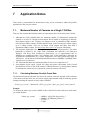
Maximum Number of Cameras on a Single 1394 Bus ................................ 29
9.1.1. Calculating Maximum Possible Frame Rate .................................. 29
9.1.2. Problems Maximizing Frame Rates ............................................... 30
Using the Camera in Single-Shot and Multi-Shot Modes ............................ 30
Interacting with External Devices ................................................................ 31
9.3.1. External Trigger Timing Information............................................... 31
9.3.2. Synchronizing to an External Device Using External Trigger Mode
31
9.3.3. Broadcasting a Strobe Pulse to an External Device ...................... 32
9.3.4. Control Shutter Time with Trigger_Mode_1 (Bulb Trigger Mode).. 32
Software Triggering an Image Acquisition................................................... 32
Working with Y16 (16-bit Mono) Images ..................................................... 33
9.5.1. Y16 Data Format ............................................................................ 33
9.5.2. Saving Y16 Images ........................................................................ 33
10
Glossary .........................................................................................34
11
Errata and Change Notifications ..................................................35
11.1.
12
Case and Adapter Revisions ..................................................................... 35
Technical Support Resources ......................................................36
12.1.
12.2.
12.3.
12.4.
Creating a Customer Login Account.......................................................... 36
Knowledge Base........................................................................................ 36
Product Downloads.................................................................................... 36
Contacting Technical Support ................................................................... 36
13
Contacting Point Grey Research Inc............................................37
14
Index ...............................................................................................38
Revised 30-Jul-08
Copyright (c) 2005 Point Grey Research Inc.
4
™
PGR Scorpion Technical Reference
1
List of Figures
Figure 1: Picture of Scorpion module (front and back)..................................................... 14
Figure 2: Scorpion case dimensions (front)...................................................................... 15
Figure 3: Scorpion case dimensions (back) ..................................................................... 15
Figure 4: Scorpion case dimensions (side) ...................................................................... 15
Figure 5: Scorpion case dimensions (bottom).................................................................. 15
Figure 6: Protective glass above CCD ............................................................................. 17
Figure 8: IEEE-1394 connector pin configuration............................................................. 19
Figure 9: GPIO pin layout ................................................................................................. 21
Figure 10: Scorpion external trigger timing characteristics .............................................. 31
2
List of Tables
Table 1: IEEE-1394 connector pin configuration.............................................................. 19
Table 2: GPIO pin assignments........................................................................................ 21
Table 3: Status indicator LED descriptions ...................................................................... 21
Table 4: Supported video formats, modes and frame rates ............................................. 23
Table 5: Supported partial image (Format 7) video formats and modes.......................... 24
Table 6: Extended shutter minimum and maximum times ............................................... 25
Table 7: Types of embedded image information .............................................................. 27
Table 8: Y16 (16-bit Mono) data format ........................................................................... 33
Revised 30-Jul-08
Copyright (c) 2005 Point Grey Research Inc.
5
™
PGR Scorpion Technical Reference
3
Introduction
3.1.
Scorpion Overview
The Scorpion IEEE-1394 camera platform, available with a variety of CMOS and CCD image
sensors, is designed for demanding imaging applications. Common to each camera model is the
form factor, the communication interface and the general purpose I/O.
All model-specific information presented in this manual reflects
functionality available in the latest version of camera firmware. To
determine this version, please refer to the Individual Model
Specifications section.
This manual attempts to provide the user with a detailed specification of the Scorpion camera
system. The reader should be aware that the camera system is a complex and dynamic system – if
any errors or omissions are found during experimentation, please contact us (see section 10.4
Contacting Technical Support).
3.2.
General Features
CCD and CMOS imaging sensors provide a wide range of
resolutions and frame rates
IEEE-1394 interface for data transmission speeds up to 400Mbps
Region of interest and pixel binning modes for faster frame rates
Camera settings control of brightness, auto exposure, gain, shutter
GPIO connector for external trigger, strobe and RS-232 serial I/O
Anodized aluminum case with top, bottom and front mounting
Automatic sync with other Scorpion’s on the same 1394 bus
Embed frame-specific info in pixels of the image
Extended shutter times up to several seconds
Firmware upgradeable in field via IEEE-1394 interface
3.3.
System Requirements
Processor
Recommended – Intel Pentium® 4 2.0 GHz or compatible processor
Minimum – Intel Pentium® III 800 MHz or compatible processor
Memory
Recommended – 512 MB RAM
Minimum - 64 MB RAM
Revised 30-Jul-08
Copyright (c) 2005 Point Grey Research Inc.
6
™
PGR Scorpion Technical Reference
3.3.1.
Desktop resolution
Recommended - 1600 × 1200
Minimum - 640 × 480
AGP video card with 64 MB video memory (128 MB recommended)
32-bit standard PCI slot for the IEEE-1394 card
Microsoft Windows XP Service Pack 1
Microsoft Visual C++ 6.0 (to compile and run example code)
Laptop / Notebook Considerations
Some 1394 PCMCIA cards for laptop / notebook computers require a 4-pin cable. A 4-pin cable
does not provide power and will therefore not work with PGR cameras, which require a 6-pin
connector (the additional two pins provide power). For suggestions on how to provide power in
these circumstances, consult the following knowledge base article:
KB Article 93:
3.3.2.
www.ptgrey.com/support/kb/index.asp?a=4&q=93
Macintosh and Linux OS Support
Users wishing to operate their PGR camera on the Macintosh OS/X or Linux operating systems
should consult the following knowledge base articles:
Macintosh support:
Linux support:
3.4.
www.ptgrey.com/support/kb/index.asp?a=4&q=173
www.ptgrey.com/support/kb/index.asp?a=4&q=17
Controlling the Camera
The Scorpion can be controlled by the following types of applications:
3.4.1.
PGR FlyCapture FlyCap Demo Program
The FlyCap application is a generic streaming image viewer included with the PGR FlyCapture
SDK that can be used to test many of the capabilities of your compatible PGR IEEE-1394
camera. It allows you to view a live video stream from the camera, save individual images or .avi
movie clips, adjust the various video formats, frame rates, properties and settings of the camera,
and access camera registers. It is an easy-to-use program that can be used to test many of the
capabilities of your PGR IEEE-1394 camera system. Consult the PGR FlyCapture User Manual
for more information.
3.4.2.
Custom Applications Built with the PGR FlyCapture API
PGR FlyCapture includes a full Application Programming Interface that allows customers to
create custom applications to control PGR Imaging Products. The SDK provides a number of
sample programs and source code that is meant to help the advanced programmer get started
using the FlyCapture API. Examples range from simple console programs that demonstrate the
basic functionality of the API, such as PGRFlyCaptureTest, to more complex examples such as
the MFC application FlyCap.
Revised 30-Jul-08
Copyright (c) 2005 Point Grey Research Inc.
7
™
PGR Scorpion Technical Reference
3.4.3.
Third-Party Software Applications
The following knowledge base article provides information on PGR IEEE-1394 camera
compatibility with third-party software development kits, applications, camera drivers, and
integrated development environments (IDEs):
KB Article 152:
3.5.
www.ptgrey.com/support/kb/index.asp?a=4&q=152
Camera Control Command Registers
For a complete description of the Camera Control Command Registers implemented on the
Scorpion, please refer to the PGR IEEE-1394 Digital Camera Register Reference, included with
the PGR FlyCapture SDK and downloadable from www.ptgrey.com/support/downloads/.
3.6.
Handling Precautions and Camera Care
Do not open the camera housing. Doing so voids the Hardware
Warranty described at the beginning of this reference manual.
Your PGR IEEE 1394 digital camera module is a precisely manufactured device and should be
handled with care. Here are some tips on how to care for the device.
Avoid electrostatic charging. Please consult the following knowledge base article for more
details: www.ptgrey.com/support/kb/index.asp?a=4&q=42.
Users who have purchased a bare board camera should be sure to take the following
additional protective measures:
o
o
Either handle bare handed or use non-chargeable gloves, clothes or material.
Also use conductive shoes.
Install a conductive mat on the floor or working table to prevent the generation of
static electricity.
When handling the camera unit, avoid touching the lenses. Fingerprints will affect the
quality of the image produced by the device.
To clean the lenses, use a standard camera lens cleaning kit or a clean dry cotton cloth. Do
not apply excessive force.
To clean the imaging surface of your CCD,
www.ptgrey.com/support/kb/index.asp?a=4&q=66.
Our cameras are designed for an office environment or laboratory use. Extended exposure to
bright sunlight, rain, dusty environments, etc. may cause problems with the electronics and
the optics of the system.
Revised 30-Jul-08
Copyright (c) 2005 Point Grey Research Inc.
follow
the
steps
outlined
in
8
™
PGR Scorpion Technical Reference
Avoid excessive shaking, dropping or any kind of mishandling of the device.
3.7.
Camera Accessories
Accessories such as tripod mounts and lens holders are available from PGR – contact our Sales
team at sales@ptgrey.com for additional information. Links to FireWire/IEEE-1394 and digital
camera accessories can be found in the following knowledge base article:
KB Article 131:
3.8.
www.ptgrey.com/support/kb/index.asp?a=4&q=131.
Related Documentation and References
The following user manuals, technical references and application notes are referred to in this
manual, and can be downloaded from www.ptgrey.com/support/downloads/:
PGR IEEE-1394 Digital Camera Register Reference
PGR FlyCapture User Manual
TAN2004004: Synchronizing to an external signal using DCAM 1.31 Trigger Mode_0
TAN2004001: Configuring and testing the RS-232 serial port
TAN2005002: Setting a GPIO pin to strobe using DCAM 1.31 Strobe Signal Output
TAN2005003: Setting a GPIO pin to output a strobe signal pulse pattern
TAN2005004: Buffering a GPIO pin output signal to drive an external device
Revised 30-Jul-08
Copyright (c) 2005 Point Grey Research Inc.
9
™
PGR Scorpion Technical Reference
4
Camera Specifications and Properties
4.1.
General Specifications
The Scorpion is available with a variety of CMOS and CCD image sensors. The following table
details the specifications common to all Scorpion models, unless otherwise specified in Individual
Model Specifications.
NOTES:
Signal-to-Noise Ratio is calculated using the general methodology outlined in the
following knowledge base article:
KB Article 142:
www.ptgrey.com/support/kb/index.asp?a=4&q=142
Specification
Description
Style
Interfaces
Silver anodized aluminum case
6-pin IEEE-1394 for camera control and video data transmission
Hirose HR10 (12-pin) for external trigger, strobe, general purpose I/O
and built-in RS232 serial port
8-32V
DCAM v1.30 Trigger_Mode_0 (except SCOR-03KD)
55dB or better at minimum gain
50mm x 50mm x 40mm
125 grams, without a lens
C- or CS-mount lens
IIDC 1394-based Digital Camera Specification v1.30
Complies with CE rules and Part 15 Class A of FCC Rules.
0 to +45C
-30 to +60C
Firmware upgrades in-field via IEEE-1394
Voltage Requirements
External Trigger
Signal-To-Noise Ratio
Dimensions
Mass
Lens Adapter
Camera Specification
Emissions Compliance
Operating Temperature
Storage Temperature
Camera Upgrades
4.2.
Individual Model Specifications
Detailed image sensor information can be found in the individual sensor datasheets, which can be
found at www.ptgrey.com/support/kb/index.asp?a=4&q=23. See the Glossary Section for
definitions of terms included in this section.
NOTES:
Current Firmware is the version currently being shipped on individual cameras; later
versions may be found at www.ptgrey.com/support/downloads. To determine a camera’s
firmware version, consult the following knowledge base article:
KB Article 94:
www.ptgrey.com/support/kb/index.asp?a=4&q=94.
Frame Rate (max) is the maximum frame rate possible using standard non-Format_7
video formats and modes.
Revised 30-Jul-08
Copyright (c) 2005 Point Grey Research Inc.
10
™
PGR Scorpion Technical Reference
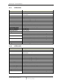
4.2.1.
SCOR-03SO
Specification
Description
Current Firmware
Sensor Overview
1.0 Release Candidate 1
Sony 1/2” ICX414 Progressive Scan CCD (Monochrome)
Global shutter
640x480
Diagonal 8mm 1/2” CCD
692(H) x 504(V) approx. 350K pixels
659(H) x 494(V) approx. 330K pixels
n/a
7.48mm(H) x 6.15mm(V)
9.9m(H) x 9.9m(V)
Analog Devices AD9849AKST (12-bit A/D)
8 bits per pixel / 16 bits per pixel digital data
Less than 2.6W
60FPS, 640x480
0.00% to 6.23%
Automatic / Manual / One-Push modes (absolute values supported)
-5.45 to 31dB
Automatic / Manual / One-Push modes (absolute values supported)
0.02ms to 16.6ms @ 60FPS
Automatic / Manual / One-Push modes (absolute values supported)
0.02ms to 1919.74ms @ 60FPS
0.50 to 4.00
DCAM v1.31 Trigger Modes 0,1 and 3
Sensor Resolution
Sensor Size
Sensor Total Pixels
Sensor Effective Pixels
Sensor Active Pixels
Sensor Chip Size
Sensor Unit Cell Size
A/D Converter
Video Output Signal
Power Consumption
Frame Rate (max)
Brightness
Gain
Shutter
Extended Shutter
Gamma
Trigger Modes
4.2.2.
SCOR-14SO
Specification
Description
Current Firmware
Sensor Overview
1.0 Release Candidate 1
Sony 1/2” ICX267 Progressive Scan CCD (Monochrome or Color)
Global shutter
1360x1024
Diagonal 8mm 1/2” CCD
1434(H) x 1050(V) approx 1.5M pixels
1392(H) x 1040(V) approx. 1.45M pixels
1360(H) x 1024(V) approx. 1.4M pixels
7.60mm(H) x 6.20mm(V)
4.65m(H) x 4.65m(V)
Analog Devices AD9849AKST (12-bit A/D)
8 bits per pixel / 16 bits per pixel digital data
Less than 3.5W
15FPS, 1280x960
0.00% to 6.23%
Automatic / Manual / One-Push modes (absolute values supported)
-10 to 26dB
Sensor Resolution
Sensor Size
Sensor Total Pixels
Sensor Effective Pixels
Sensor Active Pixels
Sensor Chip Size
Sensor Unit Cell Size
A/D Converter
Video Output Signal
Power Consumption
Frame Rate (max)
Brightness
Gain
Revised 30-Jul-08
Copyright (c) 2005 Point Grey Research Inc.
11
™
PGR Scorpion Technical Reference
Shutter
Extended Shutter
Gamma
Trigger Modes
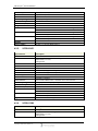
4.2.3.
Automatic / Manual / One-Push modes (absolute values supported)
0.02ms to 66ms @ 15FPS
Automatic / Manual / One-Push modes (absolute values supported)
0.02ms to 3337ms @ 15FPS
0.50 to 4.00
DCAM v1.31 Trigger Modes 0,1 and 3
SCOR-20SO
Specification
Description
Current Firmware
Sensor Overview
1.0 Release Candidate 1
Sony 1/1.8” ICX274 Progressive Scan CCD (Monochrome or Color)
Global shutter
1600x1200
Diagonal 8.923mm 1/1.8” CCD
1688(H) x 1248(V) approx. 2.11M pixels
1628(H) x 1236(V) approx. 2.01M pixels
1620(H) x 1220(V) approx. 1.98M pixels
8.50mm(H) x 6.80mm(V)
4.4m(H) x 4.4m(V)
Analog Devices AD9849AKST (12-bit A/D)
8 bits per pixel / 16 bits per pixel digital data
Less than 3.5W
15FPS, 1600x1200
0.00% to 6.23%
Automatic / Manual / One-Push modes (absolute values supported)
-10 to 26dB
Automatic / Manual / One-Push modes (absolute values supported)
0.03ms to 66.6ms @ 15FPS
Automatic / Manual / One-Push modes (absolute values supported)
0.02ms to 3296ms @ 15FPS
0.50 to 4.00
DCAM v1.31 Trigger Modes 0,1 and 3
Sensor Resolution
Sensor Size
Sensor Total Pixels
Sensor Effective Pixels
Sensor Active Pixels
Sensor Chip Size
Sensor Unit Cell Size
A/D Converter
Video Output Signal
Power Consumption
Frame Rates (max)
Brightness
Gain
Shutter
Extended Shutter
Gamma
Trigger Modes
4.2.4.
SCOR-13FF
Specification
Description
Latest Firmware
Sensor Overview
1.0 Release Candidate 1
FillFactory 2/3” IBIS-5A Progressive Scan CMOS
(Monochrome or Color)
Global / Rolling shutter
1280x1024
8.6 x 6.9mm
2/3” CMOS
1280(H) x 1024(V) approx. 1.31M pixels
1280(H) x 1024(V) approx. 1.31M pixels
1280(H) x 1024(V) approx. 1.31M pixels
Sensor Resolution
Sensor Size
Sensor Total Pixels
Sensor Effective Pixels
Sensor Active Pixels
Revised 30-Jul-08
Copyright (c) 2005 Point Grey Research Inc.
12
™
PGR Scorpion Technical Reference
Sensor Chip Size
Sensor Unit Cell Size
A/D Converter
Video Output Signal
Power Consumption
Frame Rates (max)
Brightness
Gain
Shutter
Extended Shutter
Gamma
Trigger Modes
4.2.5.
8.6mm(H) x 6.9mm(V)
6.7m(H) x 6.7m(V)
On-board the CMOS sensor - 10-bit A/D converter
8 bits per pixel digital data
Less than 2W
15FPS, 1280x960
0 to 127
Automatic / Manual / One-Push modes (absolute values supported)
3 to 14.3dB
Automatic / Manual / One-Push modes (absolute values supported)
0.07ms to 66.6ms @ 15Hz
Automatic / Manual / One-Push modes (absolute values supported)
0.07ms to 2213ms @ 1.875FPS
0.50 to 4.00
DCAM v1.31 Trigger Modes 0 and 1
SCOR-03KD
Specification
Description
Current Firmware
Sensor Overview
0.0 Beta 48
Kodak 1/3” KAC-9618/KAC-9628 Progressive Scan CMOS
(Monochrome or Color)
Rolling shutter
640x480
Diagonal 6mm 1/3” CMOS
Not available in datasheet
664(H) x 504(V) approx. 335K pixels
648 (H) x 488(V) approx. 316K pixels
Not available in datasheet
7.5m(H) x 7.5m(V)
On-board the CMOS sensor – non-linear 12-bit A/D converter
8 bits per pixel / 16 bits per pixel digital data
Less than 1.6W
30FPS, 640x480
Automatic/Manual modes
0 to 28dB
Automatic/Manual/Extended Shutter modes
0.060ms to 33ms @ 30Hz
45dB or better at minimum gain
Sensor Resolution
Sensor Size
Sensor Total Pixels
Sensor Effective Pixels
Sensor Active Pixels
Sensor Chip Size
Sensor Unit Cell Size
A/D Converter
Video Output Signal
Power Consumption
Frame Rates (max)
Gain
Shutter
Signal-To-Noise Ratio
4.2.6.
SCOR-13SM
Specification
Description
Current Firmware
Sensor Overview
0.0 Alpha 33
Symagery 2/3” VCA1281 Progressive Scan CMOS
(Monochrome or Color)
Rolling shutter
Revised 30-Jul-08
Copyright (c) 2005 Point Grey Research Inc.
13
™
PGR Scorpion Technical Reference
Sensor Resolution
Sensor Size
Sensor Total Pixels
Sensor Effective Pixels
Sensor Active Pixels
Sensor Chip Size
Sensor Unit Cell Size
A/D Converter
Video Output Signal
Power Consumption
Frame Rates (max)
Gain
Shutter
Signal-To-Noise Ratio
4.3.
1280x1024
Diagonal 11.5mm 2/3” CMOS
n/a
1284(H) x 1028(V) approx. 1.32M pixels
1280(H) x 1024(V) approx. 1.31M pixels
Not available in datasheet
7m(H) x 7m(V)
On-board the CMOS sensor - 10-bit A/D converter
8 bits per pixel digital data
Less than 4W
30FPS, 1280x960
Automatic/Manual modes
DPGA 1 to 25
Automatic/Manual/Extended Shutter modes
0.100ms to 44ms @ 15FPS
40dB or better at minimum gain
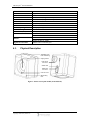
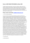
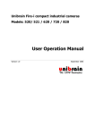
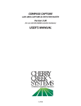
Physical Description
Adjustable C/CS
Lens Holder Ring
Imaging Sensor
12-pin GPIO
Connector
Status LED
IEEE-1394
Connector
Lens set screw
M3 Mounting
Hole
Figure 1: Picture of Scorpion module (front and back)
Revised 30-Jul-08
Copyright (c) 2005 Point Grey Research Inc.
14
™
PGR Scorpion Technical Reference
4.4.
Camera Dimensions
Figure 2: Scorpion case dimensions (front)
Figure 3: Scorpion case dimensions (back)
Figure 4: Scorpion case dimensions (side)
Figure 5: Scorpion case dimensions (bottom)
4.5.
Mounting
4.5.1.
Top and Bottom Mounts
The Scorpion is equipped with two M3 mounting holes on each of the top and bottom faces of the
case (4 holes total). These holes can be used to attach the camera directly to a custom mount or to
the Scorpion tripod mounting bracket, which can be purchased by contacting sales@ptgrey.com.
Revised 30-Jul-08
Copyright (c) 2005 Point Grey Research Inc.
15
™
PGR Scorpion Technical Reference
4.5.2.
Front Mount
The Scorpion is equipped with four M3 mounting holes on the front (sensor) face that can be used
to attach the camera directly to a custom fixture.
4.6.
Lens Setup and Compatibility
The Scorpion is compatible with both C- and CS-mount lenses. Lenses are not included with the
Scorpion camera. To differentiate between C- and CS-mount lenses, consult the following article:
KB Article 98:
4.6.1.
ptgrey.com/support/kb/index.asp?a=4&q=98
Adjusting Lens Focus
A lens M2 set screw is located on the underside of the Scorpion camera body, toward the side
closest to the lens (see the Camera Dimensions section). The set screw is used to hold the
adjustable C/CS lens holder ring (see the Physical Description section) in place once the lens is
focused. The Scorpion comes pre-focused to the standard CS-mount lens focal length (12.52mm).
Should you need to adjust the back focal length, loosen the set screw with the 0.035” (inch) hex
driver provided with the camera before adjusting the focal length.
For more information on lens focusing, consult the following knowledge base article:
KB Article 122:
4.7.
ptgrey.com/support/kb/index.asp?a=4&q=122
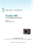
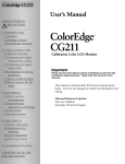
Dust Protection
Cameras are sealed when they are shipped. To avoid contamination,
seals should not be broken until cameras are ready for assembly at
customer's site.
The case is designed to prevent dust from falling directly onto the CCD's protective glass surface.
This is achieved by placing a piece of glass that is 2.5mm above the surface of the CCD's glass
(see figure below). By increasing the distance between the imaging surface and the location of the
potential dust particles, the likelihood of interference from the dust (assuming non-collimated
light) and the possibility of damage to the sensor during cleaning is reduced.
Do not remove the protective glass. Doing so can void the Hardware
Warranty described at the beginning of this reference manual.
Revised 30-Jul-08
Copyright (c) 2005 Point Grey Research Inc.
16
™
PGR Scorpion Technical Reference
Figure 6: Protective glass above CCD
4.8.
Typical Spectral Response
The spectral response curves for each sensor are in the technical datasheets available from the
individual sensor manufacturers. Datasheet links for these sensors can be found in the following
knowledge base article:
KB Article 23:
4.9.
ptgrey.com/support/kb/index.asp?a=4&q=23
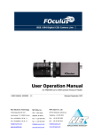
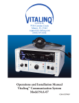
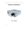
Infrared Cut-Off Filters
Scorpion cameras equipped with color sensors have an additional infrared cut-off filter included.
The approximate properties of this filter are illustrated by the IRC30 curve in the graph below.
Figure 7: IR filter transmittance graph
Revised 30-Jul-08
Copyright (c) 2005 Point Grey Research Inc.
17
™
PGR Scorpion Technical Reference
4.10.
Analog-to-Digital Converter
The Scorpion SCOR-20SO, SCOR-14SO and SCOR-03SO models incorporate an Analog
Devices AD9849AKST A/D converter in order to digitize the images produced by the CCD. The
following table illustrates the most important aspects of the processor. For more information,
please refer to the Analog Devices website at www.analog.com/.
Resolution
Description
Pixel Gain Amplifier
Variable Gain Amplifier
Black Level Clamp
Revised 30-Jul-08
Copyright (c) 2005 Point Grey Research Inc.
12-bit, 30MHz
The AD9849 is a highly integrated CCD signal processor for digital still
camera applications. It includes a complete analog front end with A/D
conversion, combined with a programmable timing driver. The
Precision Timing core allows adjustment of high-speed clocks with
approximately 1 ns resolution.
4dB +/- 6dB 6-bit
2dB to 36dB 10-bit
0 LSB to 255 LSB
18
™
PGR Scorpion Technical Reference
5
Camera Interface
5.1.
IEEE-1394 Connector
The Scorpion has a standard 6-pin IEEE-1394 connector (pin configuration shown below) that is
used for data transmission, camera control and powering the camera.
6
5
4
3
2
1
Figure 8: IEEE-1394 connector pin configuration
Pin
1
2
3
4
5
6
Function
Power Input (+8 to +32 VDC)
DC GND
TPBTPB+
TPATPA+
Table 1: IEEE-1394 connector pin configuration
5.2.
Cables
The maximum 1394a cable length between any 1394 node (e.g. camera to PCI card, PCI card to
hub, etc.) is 4.5m, as specified by the IEEE-1394 Trade Association. Standard, shielded twisted
pair copper cables must be used. Consult the following knowledge base article for information on
how to extend the physical distance between the camera and the controlling host system:
KB Article 197:
5.3.
www.ptgrey.com/support/kb/index.asp?a=4&q=197
Host Adapter Card
All Scorpion camera kits (e.g. SCOR-xxxx-KIT) come with a 3-port IEEE-1394 PCI host adapter
card built using a Texas Instruments (TI) Open Host Controller Interface. For more information
regarding the differences between various 1394 host adapters, consult the following knowledge
base article:
KB Article 146:
www.ptgrey.com/support/kb/index.asp?a=4&q=146
Revised 30-Jul-08
Copyright (c) 2005 Point Grey Research Inc.
19
™
PGR Scorpion Technical Reference
5.4.
Camera Power
The 6-pin 1394 connector connects to a standard IEEE-1394 (FireWire) 6-pin cable and provides
a power connection between the camera and the host computer. The ideal input voltage is 12V
DC; however, the camera is designed to handle voltages between 8V and 32V DC according to
the IEEE 1394 standard. The power consumption of the Scorpion varies depending on the model
(see Individual Model Specifications section).
Some systems - such as laptop computers or those with several FireWire devices connected require an external power supply to power the camera. For suggestions on how to provide power
in these circumstances, consult the following knowledge base article:
KB Article 93:
www.ptgrey.com/support/kb/index.asp?a=4&q=93
Some Scorpion models allow the user to power-up or power-down components of the camera
using the DCAM CAMERA_POWER register 0x610. The exact components, e.g. image sensor,
A/D converter, other board electronics, will vary between camera models. Consult the PGR
IEEE-1394 Digital Camera Register Reference for more information.
5.5.
General Purpose Input/Output (GPIO)
The Scorpion has a set of eight (8) general-purpose IO pins that can be accessed via the Hirose
HR10 (12-pin) external interface shown in Figure 1: Picture of Scorpion module (front and
back). These IO pins can be configured to accept an input signal to externally trigger the camera
or to send an output signal or strobe to an external device. To determine how to configure the
GPIO pins, please consult the PGR IEEE-1394 Digital Camera Register Reference.
GPIO pins IO0 to IO3 can be used for external triggering, general input/output, strobe output, or
Pulse Width Modulation (PWM) output. GPIO pins IO4 to IO7 are used for the built-in RS232
serial port. For more information on using the RS232 serial port, download Technical Application
Note TAN2004001 from www.ptgrey.com/support/downloads/.
5.5.1.
GPIO Connector Pin Layout
The following diagram shows the pin layout for the Hirose HR10 12-pin female circular
connector (Manufacturer Part Number: HR10A-10R-12SB) used on all Scorpion models. The
male counterpart Manufacturer Part Number is HR10A-10P-12P. For more information about
this connector visit the Hirose website.
Pin
GPIO
Function
Abbreviation
1
2
3
4
5
6
7
8
9 / 10
11 / 12
IO0
IO1
IO2
IO3
IO4
IO5
IO6
IO7
GND
+3.3V
Input/trigger or output/strobe (default trigger)
Input/trigger or output/strobe
Input/trigger or output/strobe
Input/trigger or output/strobe
RS232 Request to Send
RS232 Clear to Send
RS232 Transmit (Output)
RS232 Receive (Input)
RTS
CTS
TD or TX or TXD
RD or RX or RXD
Revised 30-Jul-08
Copyright (c) 2005 Point Grey Research Inc.
20
™
PGR Scorpion Technical Reference
Table 2: GPIO pin assignments
Figure 9: GPIO pin layout
5.5.2.
GPIO Electrical Characteristics
The Scorpion GPIO pins are TTL 3.3V pins protected by two diodes to +3.3V and GND in
parallel. There is also a 10K resistor in series to limit current. When configured as input, the pins
can be directly driven from a 3.3V or 5V logic output. For output, each GPIO pin has almost no
drive strength (they are high impedance) and needs to be buffered with a transistor or driver to
lower its impedance. Consult the following article for information on buffering an output signal:
KB Article 200:
www.ptgrey.com/support/kb/index.asp?a=4&q=200
The IO pins are protected from both over and under voltage. It is recommended, however, that
they only be connected to 5V or 3.3V digital logic signals.
GPIO pins IO4 to IO7 are used for the built-in RS232 serial port, and provide RS-232-compatible
signal (voltage) levels. The +3.3V pins on the Scorpion GPIO connector are fused at 200mA.
External devices connected to +3.3V should not attempt to pull anything greater than that.
5.6.
Status Indicator LED
The LED on the back of the Scorpion module provides the following general status messages:
LED Status
Off
Steady on
Steady on and very bright
Flashing bright, then brighter
Steady flashing on and off
Slow flashing on and off
Description
Not receiving power
Receiving power and successful camera initialization
Acquiring / transmitting images
Camera registers being accessed (no image acquisition)
Indicates possible camera problem
Indicates possible camera problem
Table 3: Status indicator LED descriptions
Revised 30-Jul-08
Copyright (c) 2005 Point Grey Research Inc.
21
™
PGR Scorpion Technical Reference
6
Camera Operations and Features
The Scorpion line of IEEE-1394 cameras complies with the IIDC 1394-based Digital Camera
(DCAM) Specification Version v1.30. In addition, some Scorpion models implement functionality
and video formats and frame rates outlined in the IIDC 1394-based Digital Camera (DCAM)
Specification Version v1.31. This includes improved frame rate control, trigger, parallel
input/output (PIO), serial input/output (SIO) and strobe functionality.
To determine the specific DCAM v1.31 features implemented in a particular Scorpion model,
consult the following sections of the PGR IEEE-1394 Digital Camera Register Reference.
Inquiry Registers for Basic Functions
Inquiry Registers for Feature Presence
Inquiry Registers for Feature Elements
You can query the registers described in these sections to identify whether specific features have
been implemented. For a complete description of the Camera Control Command Registers
implemented on the Scorpion, please refer to the PGR IEEE-1394 Digital Camera Register
Reference, included with the PGR FlyCapture SDK and downloadable from
www.ptgrey.com/support/downloads/.
Revised 30-Jul-08
Copyright (c) 2005 Point Grey Research Inc.
22
™
PGR Scorpion Technical Reference
6.1.
Supported Data Formats and Modes
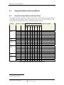
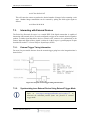
6.1.1.
Standard Formats, Modes and Frame Rates
The following sections enumerate the different non-Format 7 data formats and modes contained
in the IEEE-1394 specification that are supported by the various Scorpion models. See the
Customizable Formats and Modes section for supported Format 7 modes.
60
•
•
•
•
•
•
•
•
•
•
•
•
•
•
•
•
•
•
•
•
•
•
•
•
•
•
•
•
•
•
•
•
•
•
•
•
•
•
•
•
•
•
•
•
•
•
•
•
•
•
•
•
•
•
•
•
•
•
•
•
•
•
•
•
•
•
•
•
•
•
•
•
•
•
•
•
•
•
•
•
•
•
•
•
•
•
•
•1
•2
•
•
•
•
•
•
•
•
•
•
•
•
120
30
SCOR03NS
SCOR13SM
5
6
5
7
2
7
5
6
5
6
2
6
2
6
2
5
6
7
5
6
5
2
5
2
Mode Description
15
SCOR20SO
0
0
1
1
2
2
0
0
0
0
2
2
1
1
2
2
2
2
0
0
0
1
1
2
Frame Rate (fps)
7.5
SCOR03SO
SCOR14SO
Mode
3.75
SCOR13FF
Format
1.875
Camera
640x480 Y8 (Mono)
640x480 Y16 (Mono)
1024x768 Y8 (Mono)
1024x768 Y16 (Mono)
1280x960 Y8 (Mono)
1280x960 Y16 (Mono)
640x480 Y8 (Mono)
640x480 Y16 (Mono)
640x480 Y8 (Mono)
640x480 Y16 (Mono)
1280x960 Y8 (Mono)
1280x960 Y16 (Mono)
800x600 Y8 (Mono)
800x600 Y16 (Mono)
1280x960 Y8 (Mono)
1600x1200 Y8 (Mono)
1280x960 Y16 (Mono)
1600x1200 Y16 (Mono)
640x480 Y8 (Mono)
640x480 Y16 (Mono)
640x480 Y8 (Mono)
800x600 Y8 (Mono)
1024x768 Y8 (Mono)
1280x960 Y8 (Mono)
Table 4: Supported video formats, modes and frame rates
1
2
Actual frame rate: 25Hz
Actual frame rate: 25Hz
Revised 30-Jul-08
Copyright (c) 2005 Point Grey Research Inc.
23
™
PGR Scorpion Technical Reference
6.1.2.
Customizable Formats and Modes
The table below outlines the Format_7 custom image modes that are supported by the camera.
The implementation of these modes and the frame rates that are possible are not specified by the
DCAM.
Format_7 Mode_0 is a region of interest (sub-window) mode that allows the user to only transmit
a selected area of the image. Format_7 Mode_1 and Mode_2 are pixel binned (sub-sampled or
down-sampled) modes.
Moving the position of region of interest to a different location does not require the camera to be
stopped (isochronous transmission disabled) and restarted (iso enabled). However, changing the
size of the ROI does require the stop/start procedure.
Camera
Format Mode
Max Image
Size (HxV)
Unit Size
(H,V)
658x494
2,2
SCOR-03SO
7
0
SCOR-14SO
7
7
7
1
2
0
1392x1040
1,1
2,1
2,2
SCOR-20SO
7
7
7
1
2
0
696x520
1392x520
1628x1236
1,1
2,1
4,4
SCOR-13FF
7
7
7
1
2
0
1280x1024
1,1
2,1
4,4
SCOR-03NS
7
7
1
0
648x484
1,1
4,4
SCOR-13SM
7
7
1
0
1280x1024
4,4
7
1
-
-
Notes
Increased frame rate
82fps, 320x240
97fps, 160x120
2x2 pixel binning mode
1x2 pixel binning mode
Region of interest mode
1024x768: 21fps
640x480:
25fps
320x240:
30fps
2x2 pixel binning mode
1x2 pixel binning mode
Increased frame rate
1280x1024: 16fps
1024x768: 18fps
640x480:
21fps
320x240:
24fps
160x160:
26fps
2x2 pixel binning mode
1x2 pixel binning mode
Increased frame rate
1024x768:
43fps
640x480:
102fps
320x240:
333fps
160x120:
666fps
2x2 pixel binning mode
Increased frame rate
70fps, 320x240
119fps, 160x120
Mode not implemented
Increased frame rate
100fps, 640x480
275fps, 320x240
Mode not implemented
Table 5: Supported partial image (Format 7) video formats and modes
Revised 30-Jul-08
Copyright (c) 2005 Point Grey Research Inc.
24
™
PGR Scorpion Technical Reference
6.2.
Pixel Binning and Region of Interest Modes
Most Scorpion models implement one or more DCAM Format_7 customizable video modes (see
the Customizable Formats and Modes section for camera-specific information) that allows for
faster frame rates based on selecting a specific region of interest (ROI) of the image or by
configuring the camera to sub-sample the image using a process known as “pixel binning”. See
the following knowledge base article for a more detailed description of these modes:
KB Article 163:
6.3.
www.ptgrey.com/support/kb/index.asp?a=4&q=163
Extended Shutter Times
The maximum shutter time for some Scorpion models can be extended beyond the normal shutter
range by turning the FRAME_RATE register OFF. To do this, set the ON_OFF field of the
FRAME_RATE register 83Ch to OFF. Once the FRAME_RATE is turned off, you should see
the Max_Value of the ABS_VAL_SHUTTER register 910h increase.
The maximum extended shutter time reported by the SHUTTER_INQ
register 51Ch is capped at 4095 (0xFFF), the maximum value allowed
by the Max_Value field of this register. Use the Max_Value of the
ABS_VAL_SHUTTER register to determine the maximum shutter.
Model
Format and FPS
Min (ms)
Max (ms)
SCOR-20SO
1600x1200, 15fps
1600x1200, 7.5fps
1600x1200, 3.75fps
1600x1200, 1.875fps
1280x960, 15fps
1280x960, 7.5fps
1280x960, 3.75fps
1280x960, 1.875fps
640x480, 60fps
640x480, 30/15/7.5/3.75fps
640x480, 1.875fps
1280x960, 15fps
1280x960, 7.5
1280x960, 3.75fps
1280x960, 1.875fps
n/a
n/a
0.03
0.05
0.05
0.06
0.02
0.03
0.03
0.11
0.02
0.02
0.02
0.07
0.14
0.28
0.55
3296.99
5994.53
5994.53
23019.00
3335.85
4449.33
8898.66
30650.00
1919.74
3829.50
7673.88
276.42
552.29
1106.45
2212.89
SCOR-14SO
SCOR-03SO
SCOR-13FF
SCOR-03NS
SCOR-13SM
Notes
Table 6: Extended shutter minimum and maximum times
6.4.
Lookup Table and Gamma
All Scorpion models (except SCOR-13SM and SCOR-03KD) support lookup table (LUT) and
gamma functionality. CCD manufacturers strive to make the transfer characteristics of CCDs
Revised 30-Jul-08
Copyright (c) 2005 Point Grey Research Inc.
25
™
PGR Scorpion Technical Reference
inherently linear, which means that as the number of photons hitting the imaging sensor increases,
the resulting image intensity increases will be linear. Gamma is applied after the analog-to-digital
conversion. It can be used to apply a non-linear mapping of the resulting 10- or 12-bit image
(depending on the type of A/D converter) down to 8 bits. By default, Gamma is OFF and has a
value of 1.0, which yields a linear response.
The LUT essentially takes A/D values as inputs and allows users to map these values to 8-bit
outputs. For example, the Scorpion uses an 11-bit LUT (although it uses a 12-bit A/D converter,
the frame buffer is only large enough to accommodate 11-bit images). The LUT allows the user
to map the 211, or 2048, different possible pixel values to any one of 256 (28) possible output
values. For example, the LUT would allow the user to map any pixel with a value of 2047 (white)
to any value between 0 (black) and 255 (white).
Lookup table control is achieved using the LUT_CTRL registers, as outlined in the PGR IEEE1394 Digital Camera Register Reference.
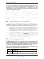
6.5.
Automatic Inter-Camera Synchronization
All Scorpion models (except SCOR-03KD), when they are on the same IEEE-1394 bus and
running at the same frame rate, are automatically synchronized to each other at the hardware
level. When using multiple cameras, the timing of one camera to another camera is as follows:
If the cameras are on the same bus, the cameras are synchronized to within 125µs
(microseconds) of each other (note: 125µs is the maximum deviation). However, the
1394 bandwidth limits the maximum number of cameras that can be on one bus. See the
section Maximum Number of Cameras on a Single 1394 Bus for more information.
If the cameras are on separate buses, a PGR Sync Unit is needed to synchronize the
cameras across buses. The Sync Unit can synchronize cameras on different buses within
the same computer or on different buses across multiple computers. This device will
ensure that the cameras are synchronized to within 125µs. If there is no sync device, there
is no timing correlation between separate cameras on separate buses.
6.6.
Embedded Image Information
All Scorpion models have a feature that allows image timing and camera settings information to
be embedded in the first several pixels of each image. The first byte of embedded image data
starts at pixel 0,0 (column 0, row 0) and continues in the first row of the image data i.e. (1,0),
(2,0), etc. This feature is enabled via the FRAME_INFO register 12F8h. Insertion of each quadlet
is controlled by a bit in the FRAME_INFO register. Timestamp is bit 31, Gain bit 30, etc.
Users using color cameras and doing Bayer color processing on the PC must extract the value
from the non-color processed image in order for the data to be valid.
Model
SCOR-13FF
SCOR-20SO
SCOR-14SO
Data Size
(quadlets)
Variable up to
9 quadlets
Revised 30-Jul-08
Copyright (c) 2005 Point Grey Research Inc.
Data Description (starting at quadlet 1)
1.
2.
3.
Timestamp
Gain
Shutter
26
™
PGR Scorpion Technical Reference
SCOR-03SO
SCOR-03KD
8 quadlets
(not variable)
SCOR-13SM
Variable up to
5 quadlets
4. Brightness
5. Exposure
6. White Balance
7. Frame Counter
8. Strobe Pattern Counter (see TAN2005003)
9. GPIO Pin State (at end of shutter)
1. Timestamp
2. Gain
3. Shutter
4. Brightness
5. Exposure
6. CMOS sensor registers [0x1D, 0x1E, 0x1F, 0x20]
7. CMOS sensor registers [0x21, 0x25, 0x26, 0x15]
8. CMOS sensor registers [0x16] and 3 zero bytes
Implements the same first five quadlets as the SCOR-13FF, etc.,
described above.
Table 7: Types of embedded image information
6.7.
Frame Rate Control
All Scorpion models (except SCOR-03KD and SCOR-13SM) allow users to fine-tune the frame
rates of their cameras using the FRAME_RATE register 0x83C, which is described in the PGR
IEEE-1394 Digital Camera Register Reference. This is particularly useful for capturing an image
stream at a different frame rate than those outlined in the Supported Data Formats and Modes
section. For example, users may wish to play an image stream back on a PAL-based system that
displays at 25FPS. This is also useful for synchronizing to 50Hz light sources, which can cause
image intensity fluctuations due to the light source oscillations being out of sync with the frame
rate.
6.8.
Programmable Strobe Output
All Scorpion models (except SCOR-03KD and SCOR-13SM) are capable of outputting a strobe
pulse off one or all of their GPIO pins. By default, a pin that is configured to be a strobe output
will output a pulse each time the camera begins integration of an image. However, some models
can also be configured to output a variable strobe pulse pattern. The strobe pattern functionality
allows users to define the frames for which the camera will output a strobe. For example, this is
useful in situations where a strobe should only fire:
Every Nth frame (e.g. odd frames from one camera and even frames from another); or
N frames in a row out of T (e.g. the last 3 frames in a set of 6); or
Specific frames within a defined period (e.g. frames 1, 5 and 7 in a set of 8).
To determine which Scorpion models support this and how to configure the variable strobe
pattern, download Technical Application Note TAN2005003 from:
KB Article 207:
www.ptgrey.com/support/kb/index.asp?a=4&q=207
Revised 30-Jul-08
Copyright (c) 2005 Point Grey Research Inc.
27
PGR Scorpion Technical Reference
6.9.
6BCamera Operations and Features
RS-232 Serial Port
All Scorpion models (except SCOR-03KD) are capable of serial communications via the onboard RS232 serial port built into the camera’s GPIO connector. For information on how to
configure the camera’s serial port, download Technical Application Note TAN2004001 from:
KB Article 151:
6.10.
www.ptgrey.com/support/kb/index.asp?a=4&q=151
Camera Upgrades
The firmware on all Scorpion models can be upgraded / downgraded to later / earlier versions
using the UpdatorGUI program that is bundled with every firmware version available from
www.ptgrey.com/support/downloads/. The latest firmware versions often include significant bug
fixes and feature enhancements that may benefit some users. To determine the changes made in a
specific firmware version, consult the Release Notes. For more information on updating camera
firmware, consult the UpdatorGUI User Manual available in the downloads section.
Revised 30-Jul-08
Copyright (c) 2005 Point Grey Research Inc.
28
PGR Scorpion Technical Reference
7
Application Notes
Application Notes
This section is recommended for advanced users only, and is not meant to address all possible
applications of the Scorpion camera.
7.1.
Maximum Number of Cameras on a Single 1394 Bus
There are four elements that limit the number of cameras that can be used on the same 1394 bus:
1. Although the 1394a standard limits the maximum number of simultaneous isochronous
channels to 16, there is currently no host adapter that is capable of supporting 16 channels.
Host adapters based on the TI chipset can support at most 4 simultaneous DMA channels
(also known as DMA contexts). Similar adapters based on the Lucent/Agere chipset support
up to 8 DMA contexts. There are no known 1394b chipsets that allow more than 4
simultaneous DMA contexts. See Knowledge Base Article 146 for more information.
2. The maximum bandwidth of the 1394a bus is 400Mbits/sec (5120Bytes/packet). The usable
bandwidth as defined by the 1394a Trade Association and enforced by the Microsoft
Windows 1394 driver stack (1394bus.sys, ohci1394.sys, etc.) is approximately 80% or
40MBytes/sec (4096Bytes/packet). The remaining 20% of the bandwidth is allocated for
asynchronous communication (e.g. register reads/writes). The same general rules apply for
1394b buses, except that the maximum bandwidth increases to 800Mbps (10240Bpp) when
1394b devices are connected.
3. The 1394a standard limits the maximum number of devices on a single bus to 63.
4. An inadequate power supply. Consult the voltage and power requirements in the General
Specifications section of your PGR camera's Technical Reference or Getting Started manual
to determine the amount of power required to operate the cameras effectively.
7.1.1.
Calculating Maximum Possible Frame Rate
The maximum frame rate allowable for each of the cameras on the bus depends on the resolution
of the cameras and the frame rate, and can be roughly approximated using the following general
formula (assuming all cameras are at the same resolution):
Frames_per_second = (Bandwidth / (Pixels_per_frame * Bytes_per_pixel)) / Num_cameras
Example:
To calculate the frames per second available to three 1024x768 Scorpions that are in 8-bit mode,
you would calculate:
Frames_per_second
Revised 30-Jul-08
Copyright (c) 2005 Point Grey Research Inc.
= (40MB/s / (1024*768*1byte/pixel)) / 3
= (40MB/s / 0.75MB/total_frames) / 3
= 53.33fps / 3
= 17.8fps
29
PGR Scorpion Technical Reference
Application Notes
You can perform a more exact calculation using the number of pixels or bytes per packet (Bpp)
that each camera is required to send when in a particular video format/mode/frame rate. The Bpp
can be derived using the "Isochronous Bandwidth Requirements" table in Section 3 of the PGR
IEEE-1394 Digital Camera Register Reference.
For example, a single PGR Scorpion SCOR-03SO in 640x480 Y16 mode running at 15fps is
sending 640 pixels per packet. Each pixel consists of 16 bits, or 2 bytes, of data. Therefore, the
camera is sending 640*2 = 1280Bpp of data. The maximum bandwidth of the 1394a bus as
discussed above is 4096Bpp, so it would be possible for 4096/1280 = 3 (rounded down) PGR
Scorpion’s to run in 640x480 Y16 mode at 15fps on the same 1394a bus.
7.1.2.
Problems Maximizing Frame Rates
In some circumstances, due to 1394 bus bandwidth limitations set by Microsoft Windows, some
cameras may not be able to achieve the maximum calculated frame rate.
Example:
According to the formula in the section Calculating Maximum Possible Frame Rate it is possible
to run four 640x480 cameras in Y8 (8-bit) mode at 30Hz. However, when attempting to do this
via the PGR software Format and Frame Rate controls, starting the fourth camera at 30Hz often
results in a “bandwidth exceeded” error.
The workaround to this problem is to circumvent the Windows bandwidth restrictions by directly
manipulating the camera’s CURRENT_FRAME_RATE register 600h. In the example above,
start three instances of the PGR FlyCapture demo program, FlyCap, with each camera running at
30Hz. Start the fourth camera up at 15Hz, then access register 600h and set the register to
0x80000000 (FrameRate_4: 30Hz).
7.2.
Using the Camera in Single-Shot and Multi-Shot Modes
It is possible to put the camera into a mode where it will grab only a single image (single-shot) or
a set number of images (multi-shot).
In order to have the camera capture a single image, the user must do the following:
1. Put the software system into a mode where it is ready to accept images from the camera. If
you are using the PGR FlyCapture software, this will require calls to flycaptureInitialize()
and flycaptureStart().
2. Ensure that isochronous data transfer is turned off by doing the following:
set 614h to 00 00 00 00
3. For a single shot, poke the first bit of the MULTI_SHOT register as follows:
set 61Ch to 80 00 00 00
For multiple shots (in this example 175, or 0xAF), poke the first bit of the MULTI_SHOT
register as follows:
Revised 30-Jul-08
Copyright (c) 2005 Point Grey Research Inc.
30
PGR Scorpion Technical Reference
Application Notes
set 61Ch to 40 00 00 AF
This will cause the camera to produce the desired number of images before resuming a wait
state. Standard image transmission can be resumed by poking the 614h register again as
follows:
set 614h to 80 00 00 00
7.3.
Interacting with External Devices
The Point Grey Research Scorpion is a versatile IEEE-1394 digital camera that is capable of
interacting with external devices. It can be configured to trigger on an external electrical signal or
produce a similar signal that allows devices external to the camera to be synchronized to the
camera. Input and output of these signals is achieved via the Scorpion’s general-purpose IO pins
described in section 5.5: General Purpose Input/Output (GPIO).
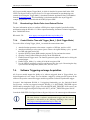
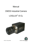
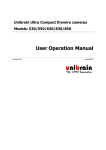
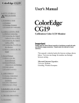
7.3.1.
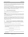
External Trigger Timing Information
For most Scorpion models the time from the external trigger going low to the integration time is
shown below:
Figure 10: Scorpion external trigger timing characteristics
7.3.2.
Synchronizing to an External Device Using External Trigger Mode
Refer to www.ptgrey.com/support/kb/index.asp?a=4&q=177 to
determine the maximum possible frame rate possible in external
trigger mode.
Revised 30-Jul-08
Copyright (c) 2005 Point Grey Research Inc.
31
PGR Scorpion Technical Reference
Application Notes
All Scorpion models support Trigger Mode_0, which is described in greater detail in the PGR
IEEE-1394 Digital Camera Register Reference. For more information on synchronizing to an
external device using the Trigger Mode_0, download Technical Application Note TAN2004004
from the downloads section. This functionality is also demonstrated in the AsyncTriggerEx
example program that is included with the PGR FlyCapture SDK.
7.3.3.
Broadcasting a Strobe Pulse to an External Device
For more information on how to configure a GPIO pin to output a signal of user-defined delay
and duration using the DCAM v1.31 strobe output functionality, download Technical Application
Note TAN2005001 from:
KB Article 179:
7.3.4.
www.ptgrey.com/support/kb/index.asp?a=4&q=179
Control Shutter Time with Trigger_Mode_1 (Bulb Trigger Mode)
To see the effects of using Trigger_Mode_1 to control the camera shutter time:
1. Attach a function generator to the camera - negative to GND pin, positive to IO2.
2. Attach an oscilloscope to the camera (just to observe the signal and duty cycle) - ground
the GND and signal lead to IO2.
3. Open the PGR FlyCapture SDK example program, FlyCap, and start the camera
4. Open the Camera Control Dialog box and go to the Extended tab
5. Enable External Trigger mode - the function generator's pulses should now be driving the
external trigger
6. Enable Trigger_Mode_1 by writing 82 01 00 00 to register 830h
7. Use the function generator to increase and decrease the duty cycle. Decreasing the duty
cycle increases the integration (shutter) time, and vice versa.
7.4.
Software Triggering an Image Acquisition
All Scorpion models support the ability to be software triggered when in Trigger Mode_0 to
begin integration of a new image. The user initiates a trigger by writing specific registers on the
camera to first put the camera into trigger mode then generate a software asynchronous trigger.
Scorpion’s that implement DCAM v1.31 triggering functionality (see the Individual Model
Specifications section) are triggered using the DCAM v1.31 SOFTWARE_TRIGGER register
0x62Ch and by setting the Trigger_Source to be the SOFTWARE_TRIGGER. All Scorpion’s can
also be software triggered using the PGR-specific SOFT_ASYNC_TRIGGER register 0x102C.
Consult the PGR IEEE-1394 Digital Camera Register Reference for camera register information.
The time between a software asynchronous trigger and the start of
integration is discussed in the following knowledge base article:
www.ptgrey.com/support/kb/index.asp?a=4&q=169
Revised 30-Jul-08
Copyright (c) 2005 Point Grey Research Inc.
32
PGR Scorpion Technical Reference
7.5.
Application Notes
Working with Y16 (16-bit Mono) Images
Most Scorpion models can output Y16 (16 bits per pixel) mono images. However, not all 16 bits
of data are useable. Models that use a 12-bit A/D converter (see Individual Model Specifications
and Analog-to-Digital Converter sections) output 12 bits of data. Models that use a 10-bit A/D
converter output 10 bits of data.
To determine the number of bits of useable image data that is actually
being produced by the A/D converter, consult the following knowledge
base article:
www.ptgrey.com/support/kb/index.asp?a=4&q=170
7.5.1.
Y16 Data Format
The data format for Y16 images is DCAM-compliant.
Description
Actual bit depth: 10bpp
Bit alignment: MSB
Byte alignment: Big-endian
Data Format
0-7
8-15
High Byte
Low Byte
Table 8: Y16 (16-bit Mono) data format
7.5.2.
Saving Y16 Images
The PGM file format can be used to correctly save 16-bit images. Following is some sample code
that can be used in conjunction with the PGR FlyCapture SDK:
FILE* fileImage = fopen( "image16.pgm", "wb" );
fprintf( fileImage, "P5\n" ); // PGM magic id value
fprintf( fileImage, "%d %d\n", image.iCols, image.iRows );
fprintf( fileImage, "%d\n", 0xFFFF ); // max value of a 16bit pixel
unsigned short* pPixel = (unsigned short*)image.pData;
for( int iPixel = 0; iPixel < image.iRows * image.iCols; iPixel++ )
{
fwrite( pPixel, 1, 2, fileImage );
pPixel++;
}
There are very few photo manipulation/display applications that can correctly display true 16-bit
images. XV in Linux and Adobe Photoshop are two possibilities.
Revised 30-Jul-08
Copyright (c) 2005 Point Grey Research Inc.
33
PGR Scorpion Technical Reference
8
Glossary
Glossary
Term
Definition
Absolute Values
Real-world values, such as milliseconds (ms), decibels (dB) or percent (%). Using
the absolute values is easier and more efficient than applying complex conversion
formulas to integer values.
Often abbreviated as ADC or A/D converted, it is a device that converts a voltage
to a digital number.
Application Programming Interface. Essentially a library of software functions.
This is the average intensity of the image. It will use other available (non-manually
adjustable) controls to adjust the image.
This is essentially the level of black in an image. A high brightness will result in a
low amount of black in the image. In the absence of noise, the minimum pixel
value in an image acquired with a brightness setting of 1% should be 1% of the
A/D converter’s minimum value.
Abbreviation for the IIDC 1394-based Digital Camera (DCAM) Specification,
which is the standard used for building FireWire-based cameras.
Programming that is inserted into programmable read-only memory, thus
becoming a permanent part of a computing device. Firmware is created and tested
like software and can be loaded onto the camera.
Encompasses partial or custom image video formats and modes, such as region of
interest of pixel binned modes. Format_7 modes and frame rates are defined by the
camera manufacturer, as opposed to the DCAM specification.
Frames Per Second.
Often defined in terms of number of frames per second (FPS) or frequency (Hz).
This is the speed at which the camera is streaming images to the host system. It
basically defines the interval between consecutive image transfers.
The amount of amplification that is applied to a pixel by the A/D converter. An
increase in gain can result in a brighter image and an increase in noise.
Gamma defines the function between incoming light level and output picture level.
Gamma can also be useful in emphasizing details in the darkest and/or brightest
regions of the image.
General Purpose Input/Output.
This is how far a color is from a gray image of the same intensity. For example,
red is highly saturated, whereas a pale pink is not.
This works by filtering the image to reduce blurred edges in an image.
This is the amount of time that the camera’s electronic shutter stays open for; also
known as the integration time. The shutter time defines the start and end point of
when light falls on the imaging sensor. At the end of the integration period, all
charges are simultaneously transferred to light-shielded areas of the sensor. The
charges are then shifted out of the light shielded areas of the sensor and read out.
Analog-to-Digital Converter
API
Auto Exposure (EV)
Brightness (%)
DCAM
Firmware
Format_7
FPS
Frame Rate
Gain (dB)
Gamma
GPIO
Saturation
Sharpness
Shutter (ms)
Revised 30-Jul-08
Copyright (c) 2005 Point Grey Research Inc.
34
PGR Scorpion Technical Reference
9
Errata and Change Notifications
Errata and Change Notifications
This errata section lists significant changes to the Scorpion hardware and electrical components
that have been implemented since the last release of the Scorpion Technical Reference. For a
summary of all firmware changes, please consult the Scorpion Firmware Release Notes.
9.1.
Case and Adapter Revisions
The following revisions pertain to the aluminum case enclosure that houses the Scorpion stacked
PCBs and the tripod mounting adapter that can be screwed to the bottom of the case.
Sticker Cutout Added - May 27, 2003
A 0.5mm deep cutout was added to the bottom of the case to allow for a sticker
containing camera information (part number, serial number, etc.).
Two Mounting Holes Added - September 12, 2003
Two (2) M2.5 tapped holes 5mm deep were added to the top of the case. This
modification was integrated into standard product design.
Multiple Mounting Holes Added – December 15, 2003
Four (4) M3 tapped holes 5mm deep added to the front of the case.
Sticker Cutout Modified – Jan 12, 2004
Size of the cutout modified.
Adapter Modified – July 2, 2004
Size of the screw holes changed to M4.
Adapter Modified – August 20, 2004
Size of the screw holes changed to M3.
Glass System Added (SCOR-14SO only) – November 14, 2004
The design of the case was modified to prevent dust from falling directly onto the
CCD's protective glass surface. This is achieved by placing a piece of glass that is
2.5mm above the surface of the CCD's glass. By increasing the distance between the
imaging surface and the location of the potential dust particles, the likelihood of
interference from the dust is reduced (assuming non-collimated light).
Revised 30-Jul-08
Copyright (c) 2005 Point Grey Research Inc.
35
PGR Scorpion Technical Reference
10
Technical Support Resources
Technical Support Resources
Point Grey Research Inc. endeavours to provide the highest level of technical support possible to
our customers. Most support resources can be accessed through the Product Support section of
our website: www.ptgrey.com/support.
10.1.
Creating a Customer Login Account
The first step in accessing our technical support resources is to obtain a Customer Login Account.
This requires a valid name, e-mail address, and camera serial number. To apply for a Customer
Login Account go to: www.ptgrey.com/support/downloads/user_request.html.
10.2.
Knowledge Base
Our on-line knowledge base contains answers to some of the most common support questions. It
has information about all PGR products and was developed to help customers resolve product
issues. It is constantly updated, expanded, and refined to ensure that our customers have access to
the latest information. To access the knowledge base, go to: www.ptgrey.com/support/kb/.
10.3.
Product Downloads
Customers with a Customer Login Account can access the latest software and firmware for their
cameras from our downloads site at www.ptgrey.com/support/downloads. We encourage our
customers to keep their software and firmware up-to-date by downloading and installing the latest
versions. These versions include the latest bug fixes and feature enhancements.
10.4.
Contacting Technical Support
Before contacting Technical Support, have you:
1. Read the product documentation and user manual?
2. Searched the Knowledge Base?
3. Downloaded and installed the latest version of software and/or firmware?
If you have done all the above and still can’t find an answer to your question, contact our
Technical Support team using our on-line web form: www.ptgrey.com/support/contact/. This will
create a ticket in our Request Tracker support system, and a Technical Support representative will
contact you by e-mail within one (1) business day.
Revised 30-Jul-08
Copyright (c) 2005 Point Grey Research Inc.
36
PGR Scorpion Technical Reference
11
Contacting Point Grey Research Inc.
Contacting Point Grey Research Inc.
For any questions, concerns or comments please contact us via the following methods:
Email:
For all general questions about Point Grey Research please
contact us at info@ptgrey.com.
For technical support (existing customers only) contact us at
http://www.ptgrey.com/support/contact/.
Knowledge
Base:
Find answers to commonly asked questions in our knowledge
base at http://www.ptgrey.com/support/kb/.
Downloads:
Users can download the latest manuals and software from
http://www.ptgrey.com/support/downloads/
Main Office:
Mailing Address:
Point Grey Research, Inc.
12051 Riverside Way
Richmond, BC, Canada
V6W 1K7
Tel: +1 (604) 242-9937
Toll-free (North America only):
+1 (866) 765-0827
Fax: +1 (604) 242-9938
sales@ptgrey.com
Mailing Address:
13749 E. Charter
Drive
Scottsdale, AZ USA
85259-2322
Tel: +1 (480) 391-2125
Fax: +1 (480) 391-2125
na-sales@ptgrey.com
Distributors
USA
Oak
Europe
Mailing Address:
Gerstäcker Str. 60
D-81827 München
Germany
Japan
ViewPLUS Inc. (http://www.viewplus.co.jp/)
Korea
Cylod Co. Ltd. (http://www.cylod.com)
Revised 30-Jul-08
Copyright (c) 2005 Point Grey Research Inc.
Tel: +49 (89) 45463224
Fax: +49 (89) 45463225
eu-sales@ptgrey.com
37
PGR Scorpion Technical Reference
12
Index
Index
1
16-bit Mono data format
F
See Y16 data format
4
4-pin 1394 cables
7
faster frame rates
firmware
changes summary
firmware version
SCOR-03NS
SCOR-03SO
SCOR-13FF
SCOR-13SM
See regions of interest
35
13
11
11, 12
13
A
A/D converter
See analog-to-digital converter
analog-to-digital converter
18
automatic synchronizationSee multiple camera
automatic synchronization
G
general purpose input/output pins
20
connector part number
20
electrical characteristics
21
GPIO
See general purpose input/output pins
B
binning
bulb trigger mode
See pixel binning
32
C
cables
camera firmware upgrades
camera settings embedded in image
capture image in single shot mode
cleaning the CCD
custom image modes
19
10
26
30
8
24
I
IIDC 1394-based Digital
Specification
image timestamp
infrared cut-off filters
input voltage
Integration time
Camera
(DCAM)
22
26
17
20
See Shutter
L
D
laptop power considerations
lens adapter formats
lens compatibility
DCAMSee IIDC 1394-based Digital Camera
(DCAM) Specification
M
E
mounting holes
multiple camera automatic synchronization
syncing cameras on different buses
embedded image timestamp
extended shutter times
maximums
external trigger timing information
26
25
25
31
Copyright (c) 2005 Point Grey Research Inc.
15
26
26
O
operating temperature
Revised 30-Jul-08
7
10
16
10
38
PGR Scorpion Technical Reference
Index
spectral response curves
storage temperature
P
PGM file format for Y16 images
PGR IEEE-1394 Digital Camera
Reference
pixel binning
powering the camera
33
Register
8, 22
25
20
R
region of interest
regions of interest
ROI
25
25
See region of interest
17
10
T
technical support resources
contacting a support representative
creating a Customer Login Account
knowledge base
on the Internet
36
36
36
36
V
voltage requirements
10
S
shutter
control shutter using Trigger_Mode_1
32
signal-to-noise ratio
10
SNR
See signal-to-noise ratio
Revised 30-Jul-08
Copyright (c) 2005 Point Grey Research Inc.
Y
Y16 data format
33
39
PGR Scorpion Technical Reference
Index
Stuff to Add
This firmware uses a
x16 speed up during high-speed vertical scanning and has a flag which
enables
leaving part of the previous image in the interline transfer buffer.
nrow
nominal fastest part-scan
====
======= ======= =========
1236:
14.7fps 14.8fps 14.8fps
1200:
14.7fps 14.8fps 15.2fps
1024:
17.0fps 17.1fps 17.4fps
960:
17.9fps 18.1fps 18.4fps
600:
26.6fps 26.7fps 28.5fps
480:
31.7fps 32.3fps 34.2fps
240:
51.4fps 52.9fps 59.6fps
120:
74.8fps 75.3fps 100.0fps
60:
96.5fps 99.4fps 147.5fps
32:
111.5fps 118.4fps 168.9fps
16:
122.5fps 130.9fps 193.4fps
[1] "nrow" is the ROI height. In Y8 mode the width doesn't matter. In
Y16 mode the width should be less than 820 columns.
[2] "nominal" is the frame rate achieved when you leave the FrameRate
CSR
[83C] in auto mode [achievable for any image offset]
[3] "fastest" is the best frame rate achievable when the row offset is
zero
and the FrameRate CSR is set to the maximum value.
[4] "part-scan" is the best frame rate achievable when the ROI is
roughly
centred vertially [roff=32*floor((1236-nrow)/32)+8] and the
FrameRate CSR
is set to the maximum value.
nrow
nominal fastest Y16 nominal
====
======= ======= ===========
1236:
14.7fps 14.8fps 14.8fps
1200:
14.7fps 15.1fps 8.1fps
1024:
17.0fps 17.6fps 9.3fps
960:
17.9fps 18.7fps 9.9fps
600:
26.6fps 27.9fps 14.7fps
480:
31.7fps 34.0fps 17.4fps
240:
51.4fps 57.8fps 28.3fps
120:
74.8fps 85.7fps 41.1fps
60:
96.5fps 118.4fps 53.0fps
32:
111.5fps 146.3fps 61.3fps
16:
122.5fps 165.9fps 67.4fps
Revised 30-Jul-08
Copyright (c) 2005 Point Grey Research Inc.
40