1
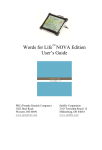
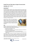
Patents pending
USER MANUAL
Distributed by:
www.BroadenedHorizons.com
Technical Support: 1-888-724-7002
info@blueskydesigns.us
1
Table of Contents
Table of Contents……………………………………………………
Page 2
Safety Tips….……………………………………………………….
Page 3
Mount’n Mover At A Glance………………………………………..
Page 4
Moving the Mount’n Mover
Using the hoop…………………………………………… Page 5
Using the paddle………………………………………… Page 5
Adjusting the angle on the tilt plate……………………. Page 5
Setting up the Mount’n Mover
Step 1: Attaching clamp to a wheelchair.….…………..
Step 2: Inserting and securing the post ………...……..
Step 3: Post adjustments……………………….............
Step 4: Attaching the Mount’n Mover to the post……...
Page 6
Page 8
Page 9
Page 10
Additional settings
Setting lock positions...………………………………….. Page 11
Fine tuning the position………………………………….. Page 12
Adjusting the friction screws…………………………….. Page 12
Using the Quick Release Plate (QRP)
Attaching the quick release plate to the tilt plate.……… Page 13
Attaching a device to the quick release plate…………. Page 14
Device-Plate attachment guide…………………………. Page 15
Breakaway feature…………………………………………………..…. Page 16
Troubleshooting………………………………………………………… Page 17
Warranty/repairs/returns…………………………………. Page 17
Technical support info……………………………………. Page 17
Technical specifications……………………………………………….. Page 18
Accessories ……………………………………..……………………… Page 20
2
SAFETY TIPS:
Read manual before using!!!
MAXIMUM load = 15 pounds
Do not use the mount to support a person
• Do not place baby or child on it
• Do not use as a means of support
when getting in or out of chair
Be sure mount is securely attached:
• Check bracket attachment to wheelchair
• Tighten mount/link to post securely
• Use thread lock on bolts as directed
• Attach device securely to Quick Release Plate
• Firmly attach Quick Release Plate/device to tilt plate
Do not attach the mount to armrests; they are often
unstable.
Move mount to a locked position before driving or
tilting the wheelchair:
• Do not unlock or move mount when wheelchair is
tilted
• Put in locked position before driving or tilting
wheelchair
Stay clear of pinch points when adjusting the tilt or
arm position
Transfers: When transferring, stow the device
close to the wheelchair; not extended out to the side—
this is especially important with a manual wheelchair.
YES
NO
OR ELSE!
3
Mount’n Mover at a Glance
(Dual arm shown)
Note: Single Arm has only the wrist and shoulder joints
Quick Release Handle
Quick
Release
Plate
Elbow
Tilt Plate
Lock Setters
Tilt
Lock
Lever
Shoulder
Friction
Adjuster
Arm
Lock Setters
Link
Post Cap
Fine
tuner
Wrist
Paddle
Post
Height
Adjustment
screw
Round Clamp: for use with
wheelchairs with round tubes
Square
Clamp
Wheelchair bracket
Cam lever
Post Cap
4
Hoop
Moving the Mount’n Mover
The Mount’n Mover can be customized to lock in specific, repeatable
positions, but it is easily unlocked and moved. The mount and device
remain in their locked positions until you use the hoop and paddle.
Move the arm by using the hoop:
• The hoop releases the shoulder and
elbow joints, allowing simultaneous
movement of the two arm segments.
• As long as the hoop is depressed, the
arm will bypass locked positions.
• When downward pressure is released,
it seeks a new lock position.
Rotate the device by first depressing the
paddle and then rotating the device directly:
• The paddle unlocks the wrist joint,
allowing rotation of the device.
• Depress, then release the paddle.
• The wrist remains unlocked until you
rotate it. Rotate the device directly.
• As you move the wrist, it will begin to
seek another lock position.
• The temporary unlock feature allows
one-handed release and rotation of
the device platform.
Adjust the tilt
•
•
•
Move the tilt lever to the unlocked position
Push down or pull up on the device
Move the lever to the locked position
Note: Different hinge torque settings are
available. This makes it easier or harder to
change the tilt. For larger devices, the High
torque hinge will prevent the device from
slamming down unintentionally.
5
Step 1: Attaching to a wheelchair
A. Determine the best attachment point and hardware required
The best attachment point depends on the person, their needs, what they
will use the mount for, the best position for access, and their wheelchair.
Most individuals need their mounted device in front of them, so it is usually
best to attach to the wheelchair or seat frame, near their knee.
When mounting consider the following:
1. Do you want the mount to tilt with the person as the seat tilts?
Yes: attach to seat rail
No: attach to base frame
Note: Attachment placement depends on the
end use: i.e., you may want a speech device to
tilt to allow communication from any angle; a
tray to be used for eating may be better
attached to the base, so it remains horizontal.
Otherwise, tilting could result in spills.
When attached to the seat rail,
Remove items which may spill or slide off
an attached tray or other surface
When attaching to the base, mount must
be moved to the side before tilting, or a
person’s legs may be squeezed and injured
2. Find one or more places to attach securely, keeping in mind:
• wheelchair bracket requires 2” space
• armrest, brake and tie down locations
• post length interference below bracket
• space required to insert or remove mount
6
3. Consider attachment options:
• Round tube clamp (7/8” and 1”)
• Adaptor plate: Holes spaced 1-2”
apart on square or rectangular frame
• T-slot nuts: Slide track or t-slot
4. Figure out the best orientation of the
bracket and/or plate to avoid other hardware
and provide best support
Note: Bracket can be attached Up or Down. The figure below shows
different placements on a tube at the same level, resulting in different
square clamp heights. The Square Clamp can also be rotated to be to
the Left or Right.
B. Attach the wheelchair bracket
•
•
•
•
Attach using lock nuts or a thread-locking product, such as Loctite.
Tighten securely.
Test holding strength once post, mount and device are attached.
Periodically check the bolts for loosening.
C. Additional mounting options
• Mounting may require optional wheelchair brackets, using the
adaptor plate as a spacer, or custom plates.
• Adaptor Plate accommodates holes spaced between 1”-2” apart.
• The Wheelchair Bracket attaches to the Adaptor with ¼-28 bolts.
• Consult BSD website for other options: www.blueskydesigns.us
7
Step 2: Inserting and securing the Post
Unlocked
A. Unlock the cam clamp lever
B. Line up the post cap ridge with the
gap in the square clamp
C. Drop the post into the square
clamp slot
D. Lock the cam clamp
Note:
If the post won’t fit into the
square clamp, or if the
post can still move up and
down when the cam
clamp is locked, try
loosening (-) or tightening
(+) the cam clamp.
8
Locked
Step 3: Post adjustments
Adjusting post height
•
•
•
The height set screw provides a
consistent mount height, limiting how
low it goes when you insert the post.
The top of the post determines the
mount height.
Once the mount is attached, the height
can be easily readjusted.
To adjust the height:
1. Loosen height set screw the appropriate
tool.
2. Move the screw up or down.
3. Tighten height set screw at desired setting.
Adjusting post angle
The post angle should be adjusted so it is
vertical with a person in their usual upright
position. This will make it easier and safer to
move.
• Once the mount is attached, the
angle can be readjusted.
1. Loosen angle set screw with a screw driver.
2. Tip the post to the preferred angle of
orientation.
3. Tighten angle set screw.
9
1
2
3
Step 4: Attaching the Mount’n Mover
to the post
A. Make sure the post is locked in position by the cam clamp
B. Slide the star shaped Link opening onto the post past the post cap
C. If the Link does not slide on easily, loosen the Link bolt using a 3/16”
hex key
D. Tighten the Link bolt with a 3/16” hex key to ensure Mount’n Mover
will not slide down on the post
E. Once Mount’n Mover is securely attached, the post height and angle
orientation can be readjusted.
Tip: The Link may be
attached in different
orientations relative to the
wheelchair, depending on an
individual’s situation.
Link
Tips and warnings:
• You can slide the Link as far
down on the post as you’d like.
• You can place two mounts on a
single post. The 15 pound
restriction is the combined
weight limit for a single
post/bracket.
• The post may limit the full
rotation and movement of the
lower arm.
• If you’re going to set it up as a
double-decker, slide the lower
one on first.
10
Setting lock positions
The basics:
• Lock setters provide repeatable, user-specific
positions.
• To set a lock position, slide a lock setter down, or to
create a bypass location, flip a lock setter up.
• To unlock a position with the friction adjustment
screw above it, the hoop or paddle must be
depressed.
• The alignment of the friction adjust screw with
a lock setter determines the lock position.
Lock position: Lock setter is down and
in line with friction adjustment screw.
Bypass position: Lock setter is up.
• Lock setting may require a small tool or pen tip
• It may be harder to set the shoulder lock setters, especially when a heavy
device is attached
Initial setup: The following is recommended for the initial setup: Slide all
lock setters up, creating bypass positions. Begin by setting lock positions at
the wrist, followed by the elbow and finally, the shoulder.
A.
B.
C.
D.
Make sure all lock setters are set into the unlocked position.
Move the arm to be oriented into a position for the end user.
Find the position of the friction adjustment screw.
Slide the lock setter closest to the friction adjustment screw to a
locked position.
E. Rotate the joint until the friction adjustment screw and lock setters
are in alignment with each other.
F. Repeat the procedure to set elbow and shoulder lock positions.
C.
D.
E.
11
Final lock position
Fine tuning the position:
Now that the desired lock positions have been set for the arm, use the
directions below to more exactly get an individualized arm placement of the
Mount’n Mover. The lock positions set a position every 30 degrees. Using
the fine tuner, you can adjust the shoulder joint to every 5 degrees.
A. Locate the fine tuner.
B. Using a thin object, such as an allen
key, push up on the fine tuner.
C. Rotate the shoulder until it sits in the
best position for the end user.
D. Release the fine tuner and move the
shoulder joint slightly until the joint finds
a locked position.
E. Have the end user try to use the device,
make adjustments as needed.
C
A
B
Adjusting the joint friction
The Mount’n Mover can be adjusted to increase or reduce the effort
required to move it. Adjustments
are made using the friction
CAUTION:
adjustment screws. Joints must be
• If you loosen the friction screw
adjusted individually.
too much, it may fall out.
• If it falls out, the plastic cap on
Locate friction adjustment screws
the joint may come off.
(see below)
•
If the screw is lost, replace it
Use a 1/16 hex key (provided):
with
a 6-32 screw.
• Turn screw clockwise = tighten
• Turn counterclockwise = loosen
12
Using the Quick Release Plate (QRP):
Attaching the QRP to the tilt plate
A. For easy access, start with the tilt plate at
an angle and in a locked position.
B. Make sure the quick release handle is in
the unlocked position.
C. Slide the QRP rounded slots at the bottom
of the plate onto the round bosses on the
tilt plate.
D. Push QRP into the tilt plate until it “clicks”
into place.
E. Push the QR handle into the locked
position.
F. Check to see if you can pull the
QRP/device away from the plate.
B.
C.
Quick Release Plate (QRP)
Tilt Plate
D.
F.
E.
13
Using the Quick Release Plate (QRP):
Attaching a device to a quick release plate
All devices attach to the quick
release plate (QRP) using
simple hardware such as
screws. Some devices require a
special device plate. These
device plates attach to both the
QRP and the device. Once a
device is attached to the QRP,
the device can be easily
attached and removed from the
tilt plate without using any tools.
See page 13.
Reference the Device-Plate Attachment Guide on the next page to
determine if any additional plates or screws are needed for the attachment
of your device to the QRP. See the diagrams below to help you determine
the appropriate attachment points between the device and the QRP.
QUICK RELEASE PLATE HOLE SETS:
Fig 1
Fig 5
Fig 2
Fig 6
Fig 3
Fig 7
14
Fig 4
Fig 8
Fig 9
Device-Plate Attachment Guide
Brand
Device
AbleNet,
Inc.
BIGmack communicator
BIG Step-by-Step
communicator
Big Red Switch
FL4SH scanning
communicator
Easy Mounting Base
iTalk2
LITTLEmack communicator
LITTLE Step-by-Step
communicator
Jelly Beamer
SuperTalker progressive
communicator
All Bluesky Designs trays
Fig 6
-
3
Device Rotation Adapter
Fig 5
Device Rotator
2
DynaVox V
DynaVox Vmax
Fig 1
-
Fig 5
DP-DV1
2
2
2
Fig 5
DP-DV1
2
4
DP-DV1
4
8-32 x 5/16”
4
8-32 x 5/8”
4
8-32 x 5/8”
-
3
8-32 x 3/8”
Blue Sky
Designs
DynaVox
QR
Plate
Hole
Set
Extra mount plate
needed
Fig 1
DP-AN1
2
2
10-32 x ½”
8-32 x 5/16”
Fig 1
DP-AN1
2
2
10-32 x ½”
8-32 x 5/16”
Fig 2
“AbleNet Easy
Mounting Base”
(Made by AbleNet)
2
2
2
8-32 x 5/16”
#8 washers
#8 nuts
Fig 3
-
2
6-32 x ½”
Place on tray/reading stand.
DynaVox DV4
DynaVox MT4
PRC
(Prentke
Romich
Company)
ECO
Pathfinder 2
Fig 5
Fig 8
Fig 7
PRC Mounting
Plates
PRC Mounting
Plates
6-32 x 3/8”
8-32 x 5/16”
(pan head)
8-32 x 5/16”
8-32 x 5/16”
8-32 x 5/16”
(pan head)
8-32 x 5/16”
8-32 x ½ “
(pan head)
SpringBoard
Fig 6
Vantage
Fig 6
-
3
8-32 x 5/8”
Fig 7
2 PRC Mounting
Plates required as
spacer
4
8-32 x 5/8”
ChatPC
Fig 9
-
3
6-32 x 3/8”
Vanguard
Saltillo
Screws Required
(Flat head Phillips
unless otherwise noted)
Qty
Type
All Other Devices
TBD
NA*
-
TBD
Tobii ATI
All Devices
TBD
NA*
-
TBD
Words +
All Devices
TBD
NA*
-
TBD
Zygo
All Devices
TBD
NA*
-
TBD
AMDI
All Devices
TBD
NA*
-
TBD
Blink
Twice
Tango
TBD
NA*
-
TBD
*Additional plates under development. For the most current list of adapter plates and hardware visit
www.blueskydesigns.us
15
BREAKAWAY FEATURE
The shoulder joint has a built-in feature where
it breaks away or dislocates if subjected to
extraordinary forces. For example, if the
mounting arm is extended out when a person
drives through a doorway, it will break away.
The mount can be easily moved back in place,
clicking into its home position. Custom lock
settings will be retained.
This feature prevents damage to mounted
devices, walls and the internal gears which
lock the post angle and fine tuner in position.
It will only break away under significant impact or
loads. It will not break away as a person reclines in a
wheelchair, provided the load restrictions are
followed.
Disabling the feature may increase the likelihood of
stripping out the post angle and fine tuner gears.
If a customer wishes to disable this feature, online
instructions are available or they can call BlueSky
Designs’ technical support at 1-888-724-7002.
16
Trouble Shooting Guide
If…
Then…
Pieces are missing
Make sure you ordered all components.
Attachment hardware is not included.
Contact company you purchased from.
Hardware arrives damaged
Contact company you purchased from.
The Mount’n Mover is not
Is the lock setter down? If not, adjust.
finding a locked position
Is hoop/paddle stuck or being held down?
Lift. p.5,11
Lock setter not able to move up Depress hoop/paddle and move arm so
into an unlocked position
friction adjuster is not above lock setter.
Lift up on or remove device while setting.
The Mount’n Mover is too
Adjust the friction adjustment screws.
difficult or too easy to move
p. 12
You are still experiencing
Call BlueSky Designs for technical
trouble with your Mount’n Mover support. 1-888-724-7002
Storage and care tips
• Keeping the mount clean and dry will increase its usability.
• Never force the mount into or out of place. Use the hoop, paddle, and tilt
lever to unlock it before attempting to reposition it.
• Set it down with care. Do not drop or throw it.
Warranty/Repair/Returns
• BlueSky Designs offers a one year warranty on the Mount’n Mover.
• If documentation of the original purchase date is not supplied, the warranty
period will be determined as twelve months from the date of manufacture,
determined by the serial number.
• This warranty is valid only with proper installation of the Mount’n Mover
according to instructions in the product manual. It does not cover repairs for
damage resulting from misuse, such as driving into walls, failing to attach it
securely, or failure to follow instructions for set-up and care.
• Please follow our repair/return policy when sending products back under our
guarantee. Before returning product for repair, please contact BlueSky
Designs for a Return Merchandise Authorization (RMA).
• BlueSky Designs offers a 30 day money back guarantee. To be eligible for a
money back guarantee, the Mount’n Mover must be in new condition.
Technical support
Call developers, BlueSky Designs, at 1-888-724-7002 or e-mail
info@blueskydesigns.us and video resources at www.GimpGear.US
17
18
19
Also available:
Single arm
Tilt’n turn
Posts
8, 12, 18, 24 inches
Custom lengths
Quick Release Plate
Device Rotator
Adaptor plate
Table Clamp
Trays
Locking Tilt Module
Visit www.GimpGear.us or call 877-6-GIMPGEAR for info on many other
unique products for individuals with upper extremity limitations!
Thanks and Acknowledgements
Developers, BlueSky Designs, thanks the Department of Education
(NIDRR) and the National Institutes of Health. Research and development
funding was provided by Small Business Innovation Research grant awards
from the Department of Education, H133S030118, and the National Institute
of Child Health and Human Development, 2 R44 HD 51157-02.
Thanks to the practitioners and consumers who gave input into the design!
20