1
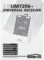
UM 7 2 0 6
UM 7 2 0 6™
UN IV E R S A L R E C E IV E R
USER MANUAL
3
G EB RAUCH SANLEIT UNG
9
G UID E UT ILISAT EUR
15
MO D O D E EMP LEO
21
MANUALE D ’IST RUZ IO NE 27
G EB RUIK SAANW IJ Z ING
33
20148/20061012 • UM7206™ UNIVERSAL RECEIVER
ALL RIG H T S RESERVED MARMIT EK © 2007
2
© MARMITEK
SAF ET Y W ARNINGS
• To prevent short circuits, this product should only be used inside and only in dry spaces. Do
not ex pose the com ponents to rain or m oisture. Do not use the product close to a bath,
sw im m ing pool etc.
• Do not ex pose the com ponents of your system s to ex trem ely hig h tem peratures or brig ht
lig ht sources.
• Do not open the product: the device m ay contain live parts. The product should only be
repaired or serviced by a q ualified repairm an.
• In case of im proper usag e or if you have opened, altered and repaired the product yourself,
all g uarantees ex pire. M arm itek does not accept responsibility in the case of im proper
usag e of the product or w hen the product is used for purposes other than specified.
M arm itek does not accept responsibility for additional dam ag e other than covered by the
leg al product responsibility.
• This product is not a toy. K eep out of reach of children.
• O nly connect the adapter to the m ains after check ing w hether the m ains voltag e is the
sam e as the values on the identification tag s. N ever connect an adapter or pow er cord
w hen it is dam ag ed. In that case, contact your supplier.
• A utom atic sw itching devices provide com fort, but can also be dang erous. They can surprise
people or can ig nite clothing hang ing over an electric heat source. P lease be careful and
tak e appropriate m easures to avoid accidents.
HO W D O ES MARMIT EK X -1 0 W O RK ?
M arm itek X -1 0 com ponents use the ex isting m ains w iring to com m unicate (using M arm itek
X -1 0 sig nals). Y ou can build a com plete system using the three different k ind of com ponents
of the M arm itek X -1 0 S ystem :
1 . Mo d u le s : These com ponents w ill receive M arm itek X -1 0 sig nals and w ill sw itch or dim the
attached lam p or appliance.
2 . Co n t r o lle r s : These com ponents w ill transm it M arm itek X -1 0 sig nals and thus w ill control
the M odules.
3 . Tr a n s m it t e r s : W ireless com ponents lik e rem otes. The sig nals of these com ponents w ill
be received by a controller w ith transceiver functionality (IR R F 7 2 4 3 , TM 1 3 or console of
a M arm itek S ecurity S ystem ). The Transceiver w ill translate the sig nals into M arm itek X -1 0
sig nals on the pow er line.
ADRESSES
U p to a m ax im um of 2 5 6 different addresses can be preset. These are subdivided into a socalled H ouseC ode (A to P incl.) and a U nitC ode (1 to 1 6 incl.). The H ouseC ode can also be set
on the controllers, so that the controllers and m odules becom e part of the sam e system . The
address can be set either using code dials or by pressing buttons, depending on the type of
m odule.
UM7206™
3
ENGLISH
UM7206™
UNIVERSAL RECEIVER
The Marmitek X-10 System uses standard commands, which control all units with the same
HouseCode at the same time (e.g. all lights on, all off, etc.).
SIGNAL RANGE
Range of Marmitek X-10 signals over the Power L ine and how to increase the range.
The Marmitek X-10 System is based on power line communication. The range of the Marmitek
X-10 signals very much depends on the local circumstances. On average the range is a cable
length of 8 0 meters.
If you have difficulties with the range of your Marmitek X-10 signals, please pay attention to
the following facts:
1. When more than one phase is used for your electrical system, it is necessary to couple these
phases for the Marmitek X-10 signals. For coupling you can use FD10 Phase Couplers/Filters.
You only need to install a Phase Coupler/Filter when your wall outlets and light switches
are divided over more than one phase (more than one group is no problem). For bigger
buildings or longer distances we advice you to use an active repeater instead of passive
FD10’s.
2. It is possible that Marmitek X-10 signals are attenuated by devices and lights which are
connected to the power line. In a normal home situation this effect is negligible (the
Marmitek X-10 system is using active gain control to eliminate the effects). However, it is
possible that a particular device in your house is attenuating the signals so much that the
range of Marmitek X-10 signals is decreased significantly. When you have range problems,
it is wise to try to locate the device which is attenuating the signals simply by unplugging
devices from the power line, and testing the differences in range for your Marmitek system.
When e.g. your conclusion is that e.g. your computer monitor is attenuating the signal,
you can use a FM10 Plug-in Filter between the power line and the monitor to eliminate the
effects.
Know n dev ic es w h ic h c an c ause attenuation are:
PC Monitors
PCs with heavy internal power supplies
Old Televisions
Copiers
Fluorescent L ights
G as Discharge L amps (E nergy Saving L amps)
3. Some (old) devices are able to disturb the signal by transmitting noise on the power line.
B ecause the Marmitek X-10 signals are transmitted on 120 kHz , only noise on or near this
frequency will have influence on the range. When you use a FM10 Filter to connect this
device to the power line, the noise will be filtered.
4. The Marmitek X-10 protocol has several mechanism to avoid modules to be switched on
or off by other sources than your Marmitek X-10 Controllers. However, it is possible that
4
© MARMITEK
5. The mains do not stop at the front door of your home. Everything that is attached to mains
nearby your home can have influence on Marmitek X-10 signals (e.g. heavy machinery).
If you think that your system is influenced by devices out of your house, it is advisable to
install FD10 Phase Coupler/Filter on each phase entering the house. These filters will block
signals coming into or going out of your house, but will also match the impedance for the
mains. Hereby make your house Marmitek X-10 compatible for these units. The FD10’s will
not only filter but will also couple the phases (please see 1).
INSTRUCTIONS FOR USE
INTRODUCTION
Thank you for buying a Marmitek X-10 UM7206 universal receiver. The UM7206 provides the
link between low-voltage appliances and the Marmitek X-10 system. The UM7206 module
receives the X-10 signal via the lighting circuit and switches lights and 24 V DC appliances
with a current up to 5 A. The UM7206 can be set to pulse or continuous contact and can be
controlled remotely with the Marmitek X-10 commands “ ON” and “ OFF” . The UM7206 is
manually operated via two keys: “ ON” (on/test) and “ OFF” . The UM7206 also has a built-in
buzzer that produces a sound when the module receives an “ ON” signal. The buzzer can, if
preferred be deactivated. If the unit is set to pulse switching with sound, the built-in buzzer
will produce three to four high-pitched bleeps. The module is powered and controlled via the
230V lighting circuit and is fitted with a mains power lead.
INSTALLATION
The module is easy to install. Connect the low-voltage appliance to the two potential-free
(dead) contacts (screw connectors) and then set the address. After connecting the plug to the
mains, the module can be operated both locally and remotely.
1.
2.
3.
4.
Using a small screwdriver, set the desired address (e.g. A1).
Connect the low-voltage appliance to the screw terminals (max. 24 V DC, 5 A).
Activate the UM7206 by connecting the plug to the mains.
Adjust the sliding switches to the preferred positions:
Sliding switch Lef t:
1. Continuous: The module switches on when it receives an ON command, and off when
it receives an OFF command.
2. Momentary: The module switches on for 3 - 5 seconds after receiving an ON command
and then switches off again.
Sliding switch Rig ht:
1. Sounder Only: Only audio signal.
2. Sounder & Relay: Audio signal and relay contact.
3. Relay Only: Only relay contact.
UM7206™
5
ENGLISH
the Marmitek X-10 signals are disturbed by e.g. baby phones which are in TALK mode
(continuous transmission). When these kind of signals are present on the power line it is
possible that the Marmitek X-10 signals will not come through.
FREQENTLY ASKED QUESTIONS
What is the reason for modules to switch on/off sp ontaneously ?
It is possible that a Marmitek X-10 System is installed at one of your neighbours using the same
House Code. To solve this problem try to change the House Code of your system, or have FD10
Phase Coupler/Filter installed at your incoming mains.
My modules will not resp ond to my controller.
Make sure that the House Code on all Modules and Controllers are set to the same House
Code (A .. P).
My modules will not react to my remote / sensor.
When you use a remote or sensor, you should have at least one TM13 Transceiver or Marmitek
X-10 Security Console installed in your house. These components will translate the radio signals
to the Marmitek X-10 signal on the power line. Using several remotes and sensors, you only
need one central transceiver.
Am I ab le to increase the range of my remotes b y using more Transceivers?
Yes, you can use more than one TM13 Transceiver in your home when the range of your remotes is
not sufficient. The TM13 is using so called collision detection to prevent signals to be disturbed when
more than one TM13 is transmitting. TM13’s will wait for a quite power line before transmitting their
data. To prevent your Marmitek X-10 System to become slow or to prevent dimming from becoming
less smooth, make sure that the TM13 units are placed as far away from each other as possible.
What is the max imum load on connections on the UM7206 module?
• Without additional protective housing: maximum 24 VDC/5A.
• With a protective housing which removes all risks of electric shocks: maximum load 230
VAC/500mA.
Do you still have questions? Please check out www.marmitek.com for more information.
TECHNICAL SP ECIFICATIONS
Power supply:
Power consumption:
Switching power:
Signal sensitivity:
Input impedance:
Responds to X-10 Key codes:
Connectors:
Ambient temperature:
Dimensions:
6
230VAC 50 Hz
< 20 mA capacitive
5A at 24 VDC
15 mVpp min., 50mVpp max. at 120 kHz
> 55 Ohm (P-N) at 120 kHz
On, Off.
2 x screw connector
-10° C to + 50° C (operation)
-20° C to + 70° C (storage)
55x9 0x38mm
© MARMITEK
European Directive 2002/96/EC requires that the equipment bearing this symbol on the product and/or its
packaging must not be disposed of with unsorted municipal waste. The symbol indicates that this product should
be disposed of separately from regular household waste streams. It is your responsibility to dispose of this and
other electric and electronic equipment via designated collection facilities appointed by the government or local authorities.
Correct disposal and recycling will help prevent potential negative consequences to the environment and human health. For
more detailed information about the disposal of your old equipment, please contact your local authorities, waste disposal
service, or the shop where you purchased the product.
UM7206™
7
ENGLISH
Environmental Information for Customers in the European Union