1
Electro Optical Components, Inc.
5460 Skylane Boulevard, Santa Rosa, CA 95403
Toll Free: 855-EOC-6300
www.eoc-inc.com | info@eoc-inc.com
rev 1.01 / 2010 07 02
rev 1.01 / 2010 07 02
QBU-BT series Pockels cell driver
User Manual
QBU-BT series Pockels cell driver
User Manual
Warning! This equipment produces high voltages that can be very dangerous.
Please read user manual before starting operations
Warning! This equipment produces high voltages that can be very dangerous.
Please read user manual before starting operations
Table of content
Table of content ................................................................................................................................... 2 Overview .............................................................................................................................................. 2 Description ........................................................................................................................................... 2 Safety ................................................................................................................................................... 3 Operations ........................................................................................................................................... 4 Operations (RS‐232 interface) ............................................................................................................... 4 Technical notes .................................................................................................................................... 5 Specifications ....................................................................................................................................... 6 Performance ........................................................................................................................................ 7 Part numbers ....................................................................................................................................... 7 Options ................................................................................................................................................ 8 Output oscillogrames ........................................................................................................................... 9 Overview
QBU-BT series Pockels cell driver produces high voltage pulses with high
repetition rates, fast risetimes and fast falltimes, adjustable voltage amplitude and
pulse width.
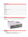
Description
Front panel:
POWER switch – turns the driver on / off
VOLTAGE indicator – shows installed voltage (in kV units)
VOLTAGE buttons – increase / decrease voltage
WIDTH indicator – shows installed pulse width (in us and ms units, pulse
width of us range has sign instead of the last digit)
WIDTH buttons – increase / decrease pulse width
REP. RATE indicator – shows installed repetition rate (in Hz and kHz units,
repetition rate of Hz range has sign instead of the last digit)
REP. RATE buttons – increase / decrease repetition rate
EXT button – switches the module between three modes
• pulses up – when this mode is selected normal state of the output is
0V, during the pulse output voltage is switched to high voltage
when this mode is selected green LED nearby the
sign is on
when this mode is selected green LED nearby the
sign is on
• pulses down – when this mode is selected normal state of the output is
high voltage level, during the pulse output voltage is switched to zero
• external synchronization mode – in this mode module receives from
SYNCHRO connector and repeats at its output external logical signal
when this mode is selected both LEDs are on
SYNCHRO connector – synchronization input for operations in external
synchronization mode
START button – enables output and starts operations in selected mode with
selected parameters; the second pressure on this button stops operations
when START button is pressed the red LED nearby indicates this
Back panel:
MAINS connector (supplied with the driver) – connects module to the mains
(110/230 VAC, 50/60 Hz). This connector contains also 5A fuse.
HV OUTPUT connector (supplied with the driver) – connects the load to the
module
RS-232 connector (optionally) – connects module to the computer
Safety
Warning! This equipment produces high voltages that can be very dangerous.
Don’t be careless around this equipment
•
•
•
•
•
•
Do not remove coverage case from the Pockels cell driver
Do not self-repair the driver
Do not operate with disconnected load
Avoid casual contacts of personnel with output cables and with the load
Do not connect / disconnect cables while driver is turned on
Do not turn the driver on if it was already damaged with water, chemicals,
mechanical or electrical shock
Operations
1. Connect Pockels cell to the driver, connect driver to the mains
2. Turn POWER switch on
3. Select desired VOLTAGE, REP. RATE, PULSE WIDTH, and
desired OPERATING MODE using corresponding buttons
4. Press START button. Since that moment module starts operations.
It must be indicated with corresponding LED
5. Press START button again to stop operations
6. Turn POWER switch off
Operations (RS-232 interface)
1.
2.
3.
4.
5.
Ensure that POWER switch is off, ensure that computer is off
Connect Pockels cell driver to the computer using corresponding cable
Turn POWER switch on, turn the computer on
Run HyperTerminal or analogous software
Send to the driver commands that set desired parameters of operations.
Send to the driver “r” command to start operations
6. Send to the driver “i” command to stop operations
7. Turn POWER switch off
Note: it’s possible but it’s not recommended to use
RS-232 and front panel user interfaces at the same time
Technical notes
• Performance of the module greatly depends on load capacitance. Full
performance (see Performance section) is achievable only under
condition of 11 pF load and below.
Higher load capacitance decreases maximal allowed repetition rate
• Module’s output is bipolar. It means that 4kV pulse is physically
formed by applying +2kV to positive output wire and –2kV to
negative (see figure)
Nevertheless, all descriptions of HV output are given in terms of
voltage differences. Please keep it in mind!
• Sometimes output is delayed. If no switching of output voltage
occurs for a long time (about 150 us) the driver needs to refresh its
state. During refreshment it’s prohibited to switch the output.
As a result if pulse width is more than 150 us or if the distance
between two sequential pulses is more than 150 us, sometimes
switching of the high voltage output may be delayed. The delay time
is about 1 us.
Specifications
ELECTRICAL SPECIFICATION
Input 110/230 VAC, 50/60 Hz; 1.0 A max
Output
Working modes Pulses up mode, pulses down mode,
repetition of external signal mode (= external
synchronization mode)
Pulse amplitude adjustable in HVmin – Hvmax range
(see Part numbers section)
Pulse basement fixed, 0 V
Pulse width 1 us – DC in external synchronization mode;
1 us – 1/f (f is repetition rate in Hz) in
internal synchronization modes
Max. repetition rate see Performance section
Risetime / falltime < 20 ns 1
Jitter ± 10 ns (± 1 ns in LJ-modification)
Delay time 1 us (100 ns in LJ-modification)
Protections from overheating
Environment
Operation Temperature 0...+40 C
Storage Temperature -20...+60 C
Humidity 90%, non-condensing
1
10-90% level, warranted at load capacitance 23 pF and below
MECHANICAL SPECIFICATION
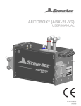
Size (LxWxH) 225 x 200 x 60 mm
Weight 1,5 kg
OUTLINE DIMENSIONS
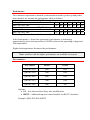
Performance
For continuous operation in internal synchronization modes (pulses up and pulses
down modes) we warrant the performance table as follows:
11 pF load capacitance
Voltage, kV
2.0 2.5 3.0 3.5 4.0 4.5 5.0
Max. rep. rate, kHz
56 40 31 24 18 15 12
23 pF load capacitance
Voltage, kV
2.0 2.5 3.0 3.5 4.0 4.5 5.0
Max. rep. rate, kHz
45 32 24 18 14 12 9
External synchronization mode shows usually a little higher performance.
In the burst-mode (= short time operations) performance is increasing
approximately twice and may achieve 100 kHz value at low operating voltage and
load capacitance.
Higher load capacitance decreases the performance.
Note: modules with the higher performance are available on request
Part numbers
Part Number
HVmax
HVmin
QBU-BT-6024
6000
2400
QBU-BT-5020
5000
2000
QBU-BT-4016
4000
1600
QBU-BT-3012
3000
1200
QBU-BT-2008
2000
800
Options:
• LJ – low jitter and low delay time modification
• RS232 – additional input to control module via RS-232 interface
Example: QBU-BT-4016-RS232
Options
LOW JITTER AND LOW DELAY TIME MODIFICATION
Standard modules have pulse delay time about 1 us, jitter about ± 10 ns.
Low jitter modification greatly decreases these parameters: delay time is
decreased to 100 ns, jitter to ± 1 ns.
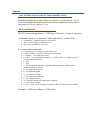
RS-232 INTERFACE
RS-232 connection parameters: 38400 bps, 8 data bits, 1 stop bit, no parity.
Command format is: {command} {data (optionally)} {end-of-line}
• command is 1 character long (see list below)
• data is ASCII-string of adjusting value
• end-of-line symbols are \r\n or \n
List of available commands:
•
•
•
•
•
•
•
•
•
•
•
•
•
•
•
f {frequency} – set frequency (repetition rate)
p {pulse width} – set pulse width (in microseconds)
v {voltage} – set voltage (in volts)
s {sync} – set synchronization type (0 – positive pulse, 1 – negative pulse, 2 –
external synchronization)
r – start
i – stop
? – get all adjusted parameters (format: frequency pulse_width voltage
synchronization op_mode)
F – get adjusted frequency
P – get adjusted length
V – get adjusted voltage
T – get temperature monitor
U – get voltage monitor
m – get both voltage and temperature monitors
Q – get current version
e {0/1} – turns on/off echoing of symbols in RS-232 (turned on by default)
Example: v 2500 sets voltage to 2500 volts.
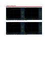
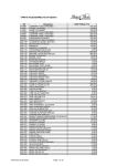
Output oscillogrames
Capacitance load 33 pF. Risetime/falltime ~25ns
Capacitance load 77 pF. Risetime/falltime ~40ns