1
CC-Link
ProLinx Gateway
CC-Link version 1.10 Local Station &
Intelligent Device
May 21, 2009
DRIVER MANUAL
Important Installation Instructions
Power, Input and Output (I/O) wiring must be in accordance with Class I, Division 2 wiring methods, Article 501-4 (b)
of the National Electrical Code, NFPA 70 for installation in the U.S., or as specified in Section 18-1J2 of the Canadian
Electrical Code for installations in Canada, and in accordance with the authority having jurisdiction. The following
warnings must be heeded:
A
B
C
D
WARNING - EXPLOSION HAZARD - SUBSTITUTION OF COMPONENTS MAY IMPAIR SUITABILITY FOR
CLASS I, DIV. 2;
WARNING - EXPLOSION HAZARD - WHEN IN HAZARDOUS LOCATIONS, TURN OFF POWER BEFORE
REPLACING OR WIRING MODULES, and
WARNING - EXPLOSION HAZARD - DO NOT DISCONNECT EQUIPMENT UNLESS POWER HAS BEEN
SWITCHED OFF OR THE AREA IS KNOWN TO BE NONHAZARDOUS.
"THIS DEVICE SHALL BE POWERED BY CLASS 2 OUTPUTS ONLY.
All ProLinx® Products
WARNING – EXPLOSION HAZARD – DO NOT DISCONNECT EQUIPMENT UNLESS POWER HAS BEEN
SWITCHED OFF OR THE AREA IS KNOWN TO BE NON-HAZARDOUS.
AVERTISSEMENT – RISQUE D'EXPLOSION – AVANT DE DÉCONNECTER L'EQUIPMENT, COUPER LE
COURANT OU S'ASSURER QUE L'EMPLACEMENT EST DÉSIGNÉ NON DANGEREUX.
Markings
ISA
ISA 12.12.01 Class I, Div 2
CSA/cUL
C22.2 No. 213-M 1987
243333
CL I Div 2 GP A, B, C, D
Temp Code T5
II 3 G
Ex nA nL IIC T5 X
0° C <= Ta <= 60° C
II – Equipment intended for above ground use (not for use in mines).
3 – Category 3 equipment, investigated for normal operation only.
G – Equipment protected against explosive gasses.
ProLinx Gateways with Ethernet Ports
Series C ProLinx™ Gateways with Ethernet ports do NOT include the HTML Web Server. The HTML Web Server
must be ordered as an option. This option requires a factory-installed hardware addition. The HTML Web Server now
supports:
8 MB file storage for HTML files and associated graphics files (previously limited to 384K)
32K maximum HTML page size (previously limited to 16K)
To upgrade a previously purchased Series C model:
Contact your ProSoft Technology distributor to order the upgrade and obtain a Returned Merchandise Authorization
(RMA) to return the unit to ProSoft Technology.
To Order a ProLinx Plus gateway with the -WEB option:
Add -WEB to the standard ProLinx part number. For example, 5201-MNET-MCM-WEB.
Your Feedback Please
We always want you to feel that you made the right decision to use our products. If you have suggestions, comments,
compliments or complaints about the product, documentation or support, please write or call us.
ProSoft Technology
5201 Truxtun Ave., 3rd Floor
Bakersfield, CA 93309
+1 (661) 716-5100
+1 (661) 716-5101 (Fax)
http://www.prosoft-technology.com
Copyright © ProSoft Technology, Inc. 2009. All Rights Reserved.
CC-Link Driver Manual
May 21, 2009
ProSoft Technology ®, ProLinx ®, inRAx ®, ProTalk®, and RadioLinx ® are Registered Trademarks of ProSoft
Technology, Inc. All other brand or product names are or may be trademarks of, and are used to identify products
and services of, their respective owners.
ProSoft Technology® Product Documentation
In an effort to conserve paper, ProSoft Technology no longer includes printed manuals with our product shipments.
User Manuals, Datasheets, Sample Ladder Files, and Configuration Files are provided on the enclosed CD, and are
available at no charge from our web site: http://www.prosoft-technology.com
Printed documentation is available for purchase. Contact ProSoft Technology for pricing and availability.
Asia Pacific: +603.7724.2080
Europe, Middle East, Africa: +33 (0) 5.3436.87.20
Latin America: +1.281.298.9109
North America: +1.661.716.5100
Contents
Driver Manual
CC-Link ♦ ProLinx Gateway
CC-Link version 1.10 Local Station & Intelligent Device
Contents
Important Installation Instructions ....................................................................................................... 2
Your Feedback Please........................................................................................................................ 3
ProSoft Technology® Product Documentation ...................................................................................3
1
CC-Link
1.1
1.2
7
Internal Database ...................................................................................................... 8
CC-Link Access to Gateway Database ..................................................................... 9
2
Install ProSoft Configuration Builder Software
10
3
Configure the Gateway
11
3.1
3.2
3.3
3.4
3.5
3.6
3.7
3.8
3.9
4
Using the Help System............................................................................................11
Adding a gateway....................................................................................................12
Module Entries ........................................................................................................13
Comment Entries.....................................................................................................13
CC-Link Protocol Configuration...............................................................................14
Configuring Transient Messages ............................................................................17
Data Map.................................................................................................................37
Printing a Configuration File ....................................................................................40
Downloading a File from PC to the Gateway ..........................................................40
Diagnostics and Troubleshooting
4.1
4.2
4.3
4.4
5
The Configuration/Debug Menu ..............................................................................43
LED Indicators.........................................................................................................47
Status Data..............................................................................................................48
Error Data................................................................................................................59
Reference
5.1
5.2
5.3
5.4
5.5
5.6
5.7
5.8
5.9
5.10
6
43
71
General Overview....................................................................................................71
CC-Link Overview ...................................................................................................72
ProLinx CCLINK User Data Memory.......................................................................74
CC-Link Cyclic Data Concepts................................................................................ 79
CC-Link Transient Data Messaging Concepts ........................................................82
Specifications ..........................................................................................................85
Conformance Testing ..............................................................................................85
RS-232 Configuration/Debug Port ..........................................................................87
DB9 to Mini-DIN Adaptor (Cable 09).......................................................................87
CC-Link Port............................................................................................................88
Support, Service & Warranty
6.1
6.2
ProSoft Technology, Inc.
May 21, 2009
89
How to Contact Us: Technical Support ...................................................................89
Return Material Authorization (RMA) Policies and Conditions................................ 90
Page 5 of 98
CC-Link ♦ ProLinx Gateway
CC-Link version 1.10 Local Station & Intelligent Device
CC-Link
Driver Manual
6.3
LIMITED WARRANTY ............................................................................................ 91
Index
97
Page 6 of 98
ProSoft Technology, Inc.
May 21, 2009
CC-Link
Driver Manual
1
CC-Link ♦ ProLinx Gateway
CC-Link version 1.10 Local Station & Intelligent Device
CC-Link
In This Chapter
Internal Database .................................................................................... 8
CC-Link Access to Gateway Database ................................................... 9
The CC-Link protocol driver acts as a Local Station or Intelligent Device, which
enables easy connection to the CC-Link Master-controlled network for data
transfer. Configuration options allow the gateway to occupy up to four (4) stations
on the CC-Link network. Transient Messaging capability increases overall I/O
data transfer capacity by more than 8,000 words. When configured as a Local
Station, the gateway allows read-only viewing of the entire CC-Link Master cyclic
database from all configured slaves on the CC-Link network.
The module is a stand-alone DIN-rail mounted protocol gateway that provides
one CC-Link TE-CON7 4P port and an Ethernet RJ45 connector interface.
CC-Link (Control & Communication Link) is an open-standard-based
communication protocol that enables easy connection to Mitsubishi PLCs, and
provides fast, reliable communication on this fieldbus network used in automation
and process control. CC-Link is the dominant protocol used in Asia, and is rapidly
gaining acceptance worldwide.
Interoperability
CC-Link technology is based on the use of an Application Specific Integrated
Circuit (ASIC) available from Mitsubishi Electric Automation.
Conformance Testing
Conformance testing through the CC-Link Partner Association (CLPA) ensures
that devices meet the performance specifications necessary to become CC-Link
certified.
Document Conventions
In this User Manual, whenever you see "CCLINK", this refers to the ProLinx
CCLINK protocol driver implementation. Whenever you see "CC-Link", this refers
to the protocol in general or to the protocol implementation on other
manufacturers' systems. These difference references allow an easy way to
identify exactly which CCLINK/CC-Link protocol implementation is being
discussed at any point in the document.
ProSoft Technology, Inc.
May 21, 2009
Page 7 of 98
CC-Link ♦ ProLinx Gateway
CC-Link version 1.10 Local Station & Intelligent Device
1.1
CC-Link
Driver Manual
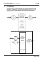
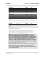
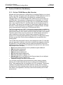
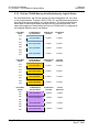
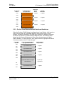
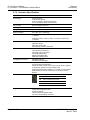
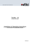
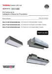
Internal Database
The module contains an internal database, which is shared between all ports on
the gateway. The database is also used to pass information from devices on one
network to devices on another network. Data from devices connected to one
communications port can be viewed and controlled by devices connected to
another port.
Ethernet
Client
Driver
Ethernet
Server
Driver
ProLinx
Communication
Gateways
Internal
Database
CC-Link
Serial
Slave
Driver
(Up to 10,000
regs)
Internal File
System
Page 8 of 98
ProSoft Technology, Inc.
May 21, 2009
CC-Link
Driver Manual
CC-Link ♦ ProLinx Gateway
CC-Link version 1.10 Local Station & Intelligent Device
You can also configure the internal database, in combination with the Memory
Map feature to retrieve and view status and error information generated by the
gateway.
1.2
CC-Link Access to Gateway Database
The CCLINK driver supports CC-Link slave functionality as a Local Station or
Intelligent Device. Gateway-supported services permit CC-Link Master
applications to read from and write to the gateway's internal database.
The internal database of the CC-Link gateway is used as the data source to
respond to CC-Link Master read requests and as the data destination for
receiving and holding data from CC-Link Master write requests. Access to the
database is dependent on the command type from the remote Master, as well as
whether the CCLINK driver has been configured to be a Local Station slave or an
Intelligent Device slave.
Before you connect the gateway to a network, verify that the network connections
are correct and that the gateway is correctly configured. You will use ProSoft
Configuration Builder (PCB) to configure the gateway and to transfer the
configuration files to and from the gateway.
ProSoft Technology, Inc.
May 21, 2009
Page 9 of 98
CC-Link ♦ ProLinx Gateway
CC-Link version 1.10 Local Station & Intelligent Device
2
Install ProSoft Configuration Builder Software
Driver Manual
Install ProSoft Configuration Builder Software
You must install the ProSoft Configuration Builder (PCB) software in order to
configure the CC-Link. You can always get the newest version of ProSoft
Configuration Builder from the ProSoft Technology web site.
To install ProSoft Configuration Builder from the ProSoft Web Site
1
2
3
4
5
Open your web browser and navigate to http://www.prosofttechnology.com/pcb
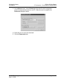
Click the DOWNLOAD HERE link to download the latest version of ProSoft
Configuration Builder.
Choose "SAVE" or "SAVE FILE" when prompted.
Save the file to your Desktop, so that you can find it easily when you have
finished downloading.
When the download is complete, locate and open the file, and then follow the
instructions on your screen to install the program.
If you do not have access to the Internet, you can install ProSoft Configuration
Builder from the ProSoft Solutions CD-ROM, included in the package with your
CC-Link.
To install ProSoft Configuration Builder from the Product CD
1
2
3
4
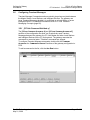
Insert the ProSoft Solutions Product CD into the CD drive of your PC. Wait for
the startup screen to appear.
On the startup screen, click PRODUCT DOCUMENTATION. This action opens an
explorer window.
Click to open the UTILITIES folder. This folder contains all of the applications
and files you will need to set up and configure your CC-Link.
Double-click the PROSOFT CONFIGURATION BUILDER SETUP program and
follow the instructions on your screen to install the software on your PC.
Note: Many of the configuration and maintenance procedures use files and other utilities on the
CD-ROM. You may wish to copy the files from the Utilities folder on the CD-ROM to a convenient
location on your hard drive.
Page 10 of 98
ProSoft Technology, Inc.
May 21, 2009
Configure the Gateway
Driver Manual
3
CC-Link ♦ ProLinx Gateway
CC-Link version 1.10 Local Station & Intelligent Device
Configure the Gateway
In This Chapter
3.1
Using the Help System .......................................................................... 11
Adding a gateway.................................................................................. 12
Module Entries ...................................................................................... 13
Comment Entries................................................................................... 13
CC-Link Protocol Configuration ............................................................. 14
Configuring Transient Messages........................................................... 17
Data Map............................................................................................... 37
Printing a Configuration File .................................................................. 40
Downloading a File from PC to the Gateway......................................... 40
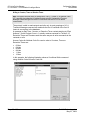
Using the Help System
Most of the information needed to help you use ProSoft Configuration Builder is
provided in a Help System that is always available whenever you are running
ProSoft Configuration Builder. The Help System does not require an Internet
connection.
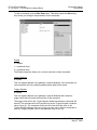
To view the help pages, start ProSoft Configuration Builder, open the HELP
menu, and then choose CONTENTS.
ProSoft Technology, Inc.
May 21, 2009
Page 11 of 98
CC-Link ♦ ProLinx Gateway
CC-Link version 1.10 Local Station & Intelligent Device
3.2
Configure the Gateway
Driver Manual
Adding a gateway
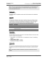
To add a gateway to your project:
1
Double-click the DEFAULT MODULE icon to open the CHOOSE MODULE TYPE
dialog box.
2
On the CHOOSE MODULE TYPE dialog box, select the gateway type.
Or
1
2
Open the PROJECT menu and choose LOCATION.
On the LOCATION menu, choose ADD MODULE.
To add a gateway to a different location:
1
Right-click the LOCATION folder and choose ADD MODULE. A new gateway
icon appears.
Or
1
2
Select the LOCATION icon.
From the PROJECT menu, select LOCATION, then select ADD MODULE.
Page 12 of 98
ProSoft Technology, Inc.
May 21, 2009
Configure the Gateway
Driver Manual
3.3
CC-Link ♦ ProLinx Gateway
CC-Link version 1.10 Local Station & Intelligent Device
Module Entries
To configure gateway parameters
1
2
3
4
3.4
to expand gateway
Click on the plus sign next to the icon
information.
Double-click the
icon to open the EDIT dialog box.
To edit a parameter, select the parameter in the left pane and make your
changes in the right pane.
Click OK to save your changes.
Comment Entries
To add comments to your configuration file:
1
2
3
icon to expand the gateway
Click the plus sign to the left of the
Comments.
Double-click the
icon. The EDIT - MODULE COMMENT dialog
appears.
Enter your comment and click OK to save your changes.
ProSoft Technology, Inc.
May 21, 2009
Page 13 of 98
CC-Link ♦ ProLinx Gateway
CC-Link version 1.10 Local Station & Intelligent Device
3.5
Configure the Gateway
Driver Manual
CC-Link Protocol Configuration
CC-Link Protocol Configuration consists of the following sections:
CCLK Config (page 15). This section defines the protocol features, gateway
memory, and port settings for the protocol
CCLink Commands Attribute x (page 17). The CCLINK driver can use
Transient Messages (page 82), in the form of CCLink Command Attributes, to
communicate with other devices on the CC-Link network.
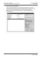
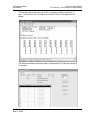
The following illustration shows the CC-Link section of the gateway configuration.
The rest of this chapter describes each parameter, with default and suggested
values.
Page 14 of 98
ProSoft Technology, Inc.
May 21, 2009
Configure the Gateway
Driver Manual
CC-Link ♦ ProLinx Gateway
CC-Link version 1.10 Local Station & Intelligent Device
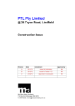
3.5.1 [CCLK Config]
This section defines the protocol features, gateway memory, and port settings for
the protocol. To edit this section, expand the CC-LINK icon in the Tree View, and
then double-click the CCLK CONFIG tag.
Enable
0 (Disable)
1 (Enable)
This setting enables or disables the CCLINK serial port on the gateway. You
must enable the port to use the CC-Link protocol.
Station Number
1 to 64 to identify the logical station
128 to place the logical station in standby mode
This value identifies stations on the CC-Link network. Each physical station must
have a unique station number. You cannot assign the same station number to
more than one station.
Note: Some CC-Link devices, including the ProLinx® CCLINK protocol gateway, allowing you to
use up to four consecutive logical slave station addresses for each physical slave station. Refer to
the Stations Occupied (page 16) parameter for more on this feature.
ProSoft Technology, Inc.
May 21, 2009
Page 15 of 98
CC-Link ♦ ProLinx Gateway
CC-Link version 1.10 Local Station & Intelligent Device
Configure the Gateway
Driver Manual
Slave Type
1 = Local Station.
A Local Station can perform Cyclic Data transmission between itself and the
Master Station, as well as, perform Transient Message transmission between
itself and the Master station or other Local Stations on the network.
2 = Intelligent Device.
In the CC-Link protocol specification, an Intelligent Device can perform Cyclic
Data transmission and Transient Message transmission only between itself and
the Master Station. An Intelligent device could not normally communicate directly
with any other slave stations on the network. However, a CCLINK gateway
configured as an Intelligent Device, can perform Transient Message
transmissions to both the CC-Link network Master Station and to other slave
stations on the network, operating as if it is configured as a Local Station.
Transmission Speed
Defines the transmission speed of the data link.
Value
156kbps
625kbps
2.5Mbps
5Mbps
10Mbps
Stations Occupied
1 to 4
Configures the number of logical slave stations used by a single physical slave
station on the network. Choose from one to four stations, depending on the
amount of Cyclic Data to be transmitted.
Times Setting
1
for all CC-Link versions
Note: The CCLINK driver currently supports only CC-Link specification version 1.10 and below.
Therefore, no other Times Settings are possible.
Alive Check
Configures whether or not to perform Alive Check:
Enable
Disable
This function enables the check to assure normal operation between the driver
software and the Q50BD-CCV2 CC-Link hardware interface board.
Page 16 of 98
ProSoft Technology, Inc.
May 21, 2009
Configure the Gateway
Driver Manual
3.6
CC-Link ♦ ProLinx Gateway
CC-Link version 1.10 Local Station & Intelligent Device
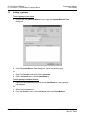
Configuring Transient Messages
Transient Message Commands send non-periodic (asynchronous) data between
the Master Station, Local Stations, and Intelligent Devices. The gateway can
issue Transient Messages whether it is configured as a Local Station or as an
Intelligent Device. For additional information, refer to CC-Link Transient
Messaging Concepts (page 82).
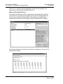
3.6.1 [CCLink Command Attribute x]
The [CCLINK COMMAND ATTRIBUTE 4] and [CCLINK COMMAND ATTRIBUTE 5]
sections of the configuration file allow you to selectively send Transient
Messages between the gateway, the CC-Link Master and other Local Stations
and Intelligent Devices on the CC-Link network. The gateway executes the
commands in numerical order. "Disabled" commands are skipped.
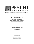
To configure Transient Message commands, double-click the COMMAND
ATTRIBUTE 4 or COMMAND ATTRIBUTE 5 sections of the gateway configuration in
PCB.
To add a command to the list, click the ADD ROW button.
ProSoft Technology, Inc.
May 21, 2009
Page 17 of 98
CC-Link ♦ ProLinx Gateway
CC-Link version 1.10 Local Station & Intelligent Device
Configure the Gateway
Driver Manual
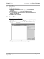
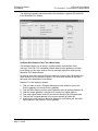
To edit a command, click the EDIT ROW button. This action opens the EDIT dialog
box, where you configure the parameters for the command.
Enable
0 = disable
1 = conditional read
2 = conditional write
The Enable parameter allows you to control execution of each command:
Internal Address
0 to 9998
This is a register address in the gateway’s internal database. If the command is a
read command, this is the starting address where data will be stored.
Trigger Register
0 to 9999
This is a register address in the gateway’s internal database that contains a
trigger value that will control the execution of this command.
The trigger value held in the Trigger Register determines when the command will
be sent. The command will not be sent as long as the Trigger Register contains a
value of zero (0). The command will be sent one time when the value in the
Trigger Register changes from zero to any non-zero value. After the command in
sent, the Trigger Register value is automatically reset to zero (0).
Page 18 of 98
ProSoft Technology, Inc.
May 21, 2009
Configure the Gateway
Driver Manual
CC-Link ♦ ProLinx Gateway
CC-Link version 1.10 Local Station & Intelligent Device
Note: In order for the Trigger Register to control command execution, the Enable parameter must
be set to 1 (Conditional Read Command) or 2 (Conditional Write Command), and the Register
Count must be greater than zero (0).
Register Count
0 to disable to 480
This is the number of registers to read or write. Set this value to 0 to disable the
command.
Swap Code
0,1,2,3
This parameter defines the byte order of each four-byte group of data received.
This parameter is helpful when dealing with floating-point or other multi-register
values, as there is no standard byte order for storing these data types. The
following table describes the values and their associated operations:
Swap Code
Description
0
None - No Change is made in the byte ordering (1234 = 1234)
1
Words - The words are swapped (1234=3412)
2
Words & Bytes - The words are swapped then the bytes in each word are
swapped (1234=4321)
3
Bytes - The bytes in each word are swapped (1234=2143)
Node Address
1 to 64, 128, 255
The Node Address parameter sets the CC-Link Station Number of the device that
will be the target for this command.
Slave Station: 1 to 64 (01h to 40h, h = hexadecimal, or base 16, numbering
system)
Master Station: 0 (00h)
Standby Master Station: 128 (80h)
Broadcast to All Station: 255 (FFh)
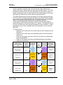
Attribute Code
4 or 5
There are two command parameters that control what kind of Transient Message
the gateway will send, the Command Attribute Code and the Command Access
Code.
Note: These values are provided for information only, are part of the command, and cannot be
modified.
ProSoft Technology, Inc.
May 21, 2009
Page 19 of 98
CC-Link ♦ ProLinx Gateway
CC-Link version 1.10 Local Station & Intelligent Device
Configure the Gateway
Driver Manual
Attribute Code 4 - Use for accessing CC-Link data that exists in the CC-Link
communication card memory buffer that is common for all CC-Link network
stations. You must specify the address offset into this common network memory
buffer according to the logical station address and type of data that you wish to
access from a particular station. This data is essentially the same as the Network
Cyclic Data that the firmware already copies to the Local Station Database in
gateway addresses 0 to1300. Therefore, this Attribute Code will have limited
practical application and has been included for protocol specification compliance.
Attribute Code 5 - Use for accessing CC-Link database memory on any station
capable of receiving and sending Transient Messages. This Attribute Code is
more useful than Attribute Code 4 because it extends data access to a wider
range of data types beyond common Cyclic Data and common buffer data.
Attribute Code 5 can be used to access timers, counters, link and status data, as
well as input/output bit and registers, and more.
Access Code
Various values entered as hexadecimal codes
There are two command parameters that control what kind of Transient Message
the gateway will send, the Command Attribute Code and the Command Access
Code. Each of the two Attribute Codes have different Access Codes associated
with them. Even though some of the same hexadecimal values are used as
Access Codes for both Attribute Codes, it is the combined Attribute Code/Access
Code pair which determine the exact type of command transmitted.
Which Access Code you can use in a command depends on the selected
Attribute Code, 4 or 5, discussed above. Refer to the following tables for a
description of the available Access Codes for each Attribute Code.
Access Codes for Attribute 4
Device Contents
Access Code
Buffer in the Intelligent Device Station
00h
Random access buffer
20h
Remote input
21h
Remote output
22h
Link special relay
63h
Link special register
64h
Remote register
24h
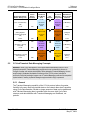
Access Codes for Attribute 5
Device Contents
Name
Input relay
X
Output relay
Y
Internal relay
M
Latch relay
Link relay
Page 20 of 98
Bit
Word
Unit
Access Code
O
Hexadecimal
01h
O
Hexadecimal
02h
O
Decimal
03h
L
O
Decimal
83h
B
O
Hexadecimal
23h
ProSoft Technology, Inc.
May 21, 2009
Configure the Gateway
Driver Manual
CC-Link ♦ ProLinx Gateway
CC-Link version 1.10 Local Station & Intelligent Device
Device Contents
Name
Bit
Timer (contact)
T
O
Timer (coil)
T
O
Timer (present value)
T
Retentive timer (contact)
ST
Retentive timer (coil)
Word
Unit
Access Code
Decimal
09h
Decimal
0Ah
Decimal
0Ch
O
Decimal
89h
ST
O
Decimal
8Ah
Retentive timer (present
value)
ST
O
Decimal
8Ch
Counter (contact)
C
O
Decimal
11h
Counter (coil)
C
O
Decimal
12h
Counter (present value)
C
O
Decimal
14h
Data register
D
O
Decimal
04h
Link register
W
O
Hexadecimal
24h
File register
R
O
Decimal
84h
Special link relay
SB
Hexadecimal
63h
Special link register
SW
O
Hexadecimal
64h
Decimal
43h
O
Decimal
44h
Special relay
SM
Special register
SD
O
O
O
Note: Device Contents (data areas or data types) other than those shown above cannot be
accessed.
Transient Message Bit-level Access
Both Command Attribute Code 4 and Command Attribute Code 5 have
Command Access Codes that allow transfer of binary, bit-level data. The
following cautionary Note and Warning apply to all Transient Message
Commands used to access binary or bit-level data types.
Note: Binary bit-level data may not be accessed as single or individual bits, but only in 16-bit,
whole-word groupings. When accessing bit-level data, the bits will always be read or written
starting on an even 16-bit word boundary in the target database. That is to say that all reads and
writes will start at Bit 0 of the word address used in the command. For hexadecimal addresses, the
right-most bit = 0 will indicate a word-level boundary bit address (0000h, 0010h, 01C0h, etc.)
Therefore, when accessing a bit device (such as Input Relay, Output Relay, Timer (coil), Counter
(contact), and so on), you must specify the Offset Address in the command as a word address by
first converting any hexadecimal address to its decimal equivalent and then divide the bit address
by 16. Next, drop any remainder (no decimal point fractions allowed) and the integer result of this
division then becomes the Offset Address for the command.
Example: Input Relay 5Ah = 90 decimal / 16 = 5.625 = Bit 10 of register 5. Offset [word] Address =
5.
When dealing with hexadecimal (hex or h) addresses, a shortcut alternative to doing this
calculation would be to drop the right-most digit in the hex address and convert the remaining digit
or digits to their decimal equivalent.
ProSoft Technology, Inc.
May 21, 2009
Page 21 of 98
CC-Link ♦ ProLinx Gateway
CC-Link version 1.10 Local Station & Intelligent Device
Configure the Gateway
Driver Manual
Example: Timer (coil) 01CAh - Drop the A & convert 01Ch to decimal. Offset [word] Address = 28.
To access individual bits, you will have to read the entire word containing the bit or bits you wish to
access. If you wish to change the value of specific bits, you will need read the entire word
containing the bit or bits you wish to change, employ a bit-masking technique to change only the
bits you want to change, and then write back the entire data word containing the changed bits.
WARNING: Anyone creating and using Transient Messages to write bit-level data must use
extreme care must be exercised with any bit-masking procedure to avoid unwanted data changes
that could result in unexpected equipment operation, which might cause damage to equipment or
injury to personnel.
Offset Address
0 and up, always entered as a decimal (base 10) value
This parameter sets the address offset of a memory area in the CC-Link
hardware memory buffer or in the memory database area on a remote station
that will be affected by the command. The values to use here will vary based on
the Command Attribute Code, Command Access Code, the type of data to be
accessed, and the location of that data in the target data area or device.
Even though many CC-Link devices specify memory addresses using
hexadecimal numbers, this parameter must always be entered into the PCB
Command configuration as the decimal (base 10) equivalent of any hexadecimal
address value. If necessary, convert any hexadecimal addresses to decimal
numbers before entering the value into this parameter. For additional details,
refer to Transient Message Bit-level Access (page 21).
Example: If X100h is the start of your Remote Inputs (RX data area) in a CC-Link Master PLC,
then:
The Offset Address to the beginning of the RX data area will be 0 to read the
data from X100h through X10Fh.
To read from the Master RX bit addresses starting at X110h through X11Fh
use Offset Address 1.
To read X120h through X12Fh use Offset Address 2, and so on.
Comment
0 to 35 alphanumeric characters
Page 22 of 98
ProSoft Technology, Inc.
May 21, 2009
Configure the Gateway
Driver Manual
CC-Link ♦ ProLinx Gateway
CC-Link version 1.10 Local Station & Intelligent Device
3.6.2 Example Commands
The following command examples show how to read and write data from the CCLink network using Transient Messages. These examples show several of the
most typical types of Transient Messages you might need to use. They are not
meant to be an exhaustive reference of all possible Attribute Code/Access Code
combinations, only to present a few, well-chosen, representative ones.
Command Attribute Code 4
Command Attribute Code 4 is used to access the network data buffer on the CCLink hardware interface card on the ProLinx gateway or on a remote Station. The
lowest Offset Address for all listed Access Codes will be zero, except for Access
Code 24h, which must be treated differently.
An Access Code 24h write command accesses the write register area of the data
buffer, which starts at Offset Address 0 (00h). An Access Code 24h read
command accesses the read register area of the data buffer, which starts at
Offset Address 256 (100h).
For a list of the Access Codes available for Attribute Code 4, refer to Access
Codes for Attribute 4 (page 20).
Note: Access Codes 21h, 22h, and 63h access binary bit data. Refer to note on Bit-level Access
(page 21).
ProSoft Technology, Inc.
May 21, 2009
Page 23 of 98
CC-Link ♦ ProLinx Gateway
CC-Link version 1.10 Local Station & Intelligent Device
Configure the Gateway
Driver Manual
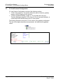
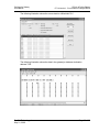
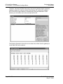
You can view the Command List from the gateways Config/Debug menu. The
following illustration shows an example Command List for commands 0 to 9.
To execute any command entered in the list, use the database Trigger Register,
which can be controlled by the other protocol on the gateway. Set the Trigger
Register to any non-zero value to cause the command to be transmitted. The
Trigger Register value will reset to zero every time the associated command is
executed.
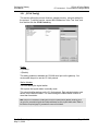
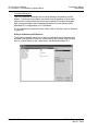
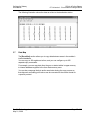
Conditional Read Example
This example issues a Transient Message conditional read with Attribute Code
4/Access Code 24h. This command attempts to read data from the Master at
offset 256 (0100 Hex), which is the start of the RWr register area in the buffer.
Data will be placed in the gateway at address 6000. To execute this command,
change register 5100 to any non-zero value.
Page 24 of 98
ProSoft Technology, Inc.
May 21, 2009
Configure the Gateway
Driver Manual
CC-Link ♦ ProLinx Gateway
CC-Link version 1.10 Local Station & Intelligent Device
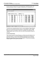
The following illustration shows the command in ProSoft Configuration Builder.
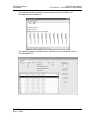
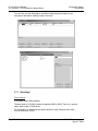
The following illustration shows the source data in a Mitsubishi PLC (notice the
Device addresses in the Mitsubishi are shown as hexadecimal values preceded
by the letter "D". Each address is a 16-bit register.)
ProSoft Technology, Inc.
May 21, 2009
Page 25 of 98
CC-Link ♦ ProLinx Gateway
CC-Link version 1.10 Local Station & Intelligent Device
Configure the Gateway
Driver Manual
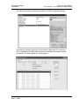
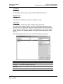
The following illustration shows the data in the gateway's database destination
address 6000.
Remote Inputs Example
This example issues a Transient Message conditional read with Attribute Code
4/Access Code 21h, which reads the Remote Inputs (RX area). This command
will read 16 inputs bits (1 register word), and will place the data in the gateway’s
database register 6008.
The following illustration shows the command in ProSoft Configuration Builder.
Page 26 of 98
ProSoft Technology, Inc.
May 21, 2009
Configure the Gateway
Driver Manual
CC-Link ♦ ProLinx Gateway
CC-Link version 1.10 Local Station & Intelligent Device
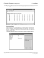
The following illustration shows the source data in a Mitsubishi PLC. Notice that
the beginning of the RX data area in the Master is bit address X100. Because
X100 is the first register of the RX data area, using Offset Address = 0 and
Access Code = 21h in the PCB command will allow the command to read at the
start of the RX data area in the Master.
The following illustration shows the source data in the gateway’s database
destination address 6008.
ProSoft Technology, Inc.
May 21, 2009
Page 27 of 98
CC-Link ♦ ProLinx Gateway
CC-Link version 1.10 Local Station & Intelligent Device
Configure the Gateway
Driver Manual
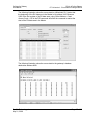
Entering the Command Offset Address
This is an example command for ProSoft Configuration Builder to show how to
read Special Link Relay (bit-level data) from address SB60h using Attribute Code
4/Access Code 63h. For additional information on how to convert bit-level
addresses into Offset [word] Addresses, refer to Transient Message Bit-level
Access (page 21)
Page 28 of 98
ProSoft Technology, Inc.
May 21, 2009
Configure the Gateway
Driver Manual
CC-Link ♦ ProLinx Gateway
CC-Link version 1.10 Local Station & Intelligent Device
The following illustration shows the source data in a Mitsubishi PLC.
The following illustration shows the data in the gateway’s database destination
address 7002.
ProSoft Technology, Inc.
May 21, 2009
Page 29 of 98
CC-Link ♦ ProLinx Gateway
CC-Link version 1.10 Local Station & Intelligent Device
Configure the Gateway
Driver Manual
Command Attribute 5
This set of transient messages can be issued between the gateway and the
Master. You can also issue these commands from the gateway to other slave
stations on the network that can receive and respond to Transient Messages.
Most of these examples show messages between a ProLinx gateway and a
Mitsubishi PLC configured as a CC-Link Master.
For a complete list of potential Access Codes, refer to Access Codes for Attribute
5 (page 20).
Writing to the Remote Input RX Data Area
The following example shows how to send a conditional write command using
Attribute Code 5/Access Code 01h, which writes to the Remote Input RX data
area or a Local Station or the X data area in the Mitsubishi Master PLC.
Page 30 of 98
ProSoft Technology, Inc.
May 21, 2009
Configure the Gateway
Driver Manual
CC-Link ♦ ProLinx Gateway
CC-Link version 1.10 Local Station & Intelligent Device
The following illustration shows the source data to be sent to the Master PLC
from gateway source address 0.
The following illustration shows the data in destination X20 (word offsets 2 and 3)
in the Mitsubishi PLC.
ProSoft Technology, Inc.
May 21, 2009
Page 31 of 98
CC-Link ♦ ProLinx Gateway
CC-Link version 1.10 Local Station & Intelligent Device
Configure the Gateway
Driver Manual
Writing to Counters, Timers or Retentive Timers
Note Take special care when writing or reading from a Timer (T), Counter (C) or Retentive Timers
(ST), especially when attempting to read their contacts and coils. Careless use of Transient
Messages to these data types can cause PLC faults and/or total loss of CC-Link network
communication.
The protocol is able to read contacts and coils only in word groupings of 16. A
Transient Message command will read/write the first 16 contacts of the first 16
timers in one register in the database.
A message to read Timer, Counter, or Retentive Timer contacts starting at Offset
Address = 0 with Register Count = 1 actually retrieves contacts for Timers 0-15.
Retentive Timers and Counters work the same way as do write commands to the
contacts or coils.
Access Codes for Attribute Code 5 to read or write to Counters, Timers or
Retentive Timers are:
09 Hex
0A Hex
89 Hex
8A Hex
11 Hex
12 Hex
In this example, the following illustration shows a Conditional Write command
using Attribute Code 5/Access Code 09h.
Page 32 of 98
ProSoft Technology, Inc.
May 21, 2009
Configure the Gateway
Driver Manual
CC-Link ♦ ProLinx Gateway
CC-Link version 1.10 Local Station & Intelligent Device
This message will retrieve data value 847 from gateway database locations 10
and 11, and write the first 32 contacts of the first 32 timers to the Mitsubishi PLC
Master.
The following illustration shows the data in the Mitsubishi PLC after the command
is executed.
ProSoft Technology, Inc.
May 21, 2009
Page 33 of 98
CC-Link ♦ ProLinx Gateway
CC-Link version 1.10 Local Station & Intelligent Device
Configure the Gateway
Driver Manual
Timers 0 to 31 contain the same data pattern as that from the gateway. The
binary value of 847 decimal is 0000001101001111.
Writing to the File Register Data Type
This example shows how to send a conditional write command using Attribute
Code 5/Access Code 84h. This command writes to the File Register data type
(R) from source address 0032 and 0033 in the gateway, to the destination
registers R45 and R46 in the File Register data to the Mitsubishi PLC Master.
The following illustration shows the source data in the gateway to be sent to the
Mitsubishi PLC Master.
Page 34 of 98
ProSoft Technology, Inc.
May 21, 2009
Configure the Gateway
Driver Manual
CC-Link ♦ ProLinx Gateway
CC-Link version 1.10 Local Station & Intelligent Device
The following illustration shows the data in the destination registers R45 and R46
in the Mitsubishi PLC Master.
Conditional Write Example to Other Than a Master Station
This example shows how to set up a conditional write with Attribute Code
5/Access Code 24h. This command will write data from the gateway to another
Local Station (in this case, another ProLinx gateway) rather than writing to the
Mitsubishi PLC Master Station.
In order to write to the correct offset and because Access Code 24h writes to the
RWw data area of the destination station, you must know the start of the RWw
data area in the destination Local Station.
Example: For this example, assume:
1
2
3
4
5
6
That you want to send a Transient Message to write data from your local
ProLinx gateway to a remote ProLinx gateway
That the RWw data area of the remote gateway starts at gateway address 40
That the remote gateway is configured to occupy four logical stations
That each logical station uses four consecutive words in the RWs data area
That the first occupied address in the remote gateway is Station #2
And that you want to write to the Node Address (Local Station) #5, the fourth
logical station in the Remote ProLinx gateway.
ProSoft Technology, Inc.
May 21, 2009
Page 35 of 98
CC-Link ♦ ProLinx Gateway
CC-Link version 1.10 Local Station & Intelligent Device
Configure the Gateway
Driver Manual
Therefore, because the RWw data area in the remote gateway begins at gateway
database register 40, which would be Offset Address 40, and you are trying to
write to the fourth logical station in that data area, then the destination Offset
Address you will need to use in the command will be 52.
The following illustration shows the source data to be written from the gateway to
Local Station #5 on the network.
Page 36 of 98
ProSoft Technology, Inc.
May 21, 2009
Configure the Gateway
Driver Manual
CC-Link ♦ ProLinx Gateway
CC-Link version 1.10 Local Station & Intelligent Device
The following illustration shows the data as written to the destination station.
3.7
Data Map
The [DATA MAP] section allows you to copy data between areas in the module’s
internal database.
You can copy to 100 registers at a time, and you can configure up to 200
separate copy commands.
For example, you can copy data from the error or status tables in upper memory
to internal database registers in the User Data memory area.
You can also rearrange the byte and/or word order during the copy process so
that data such as floating point values can be converted to the correct format for
a specific protocol.
ProSoft Technology, Inc.
May 21, 2009
Page 37 of 98
CC-Link ♦ ProLinx Gateway
CC-Link version 1.10 Local Station & Intelligent Device
Configure the Gateway
Driver Manual
You can also use the Data Map to condense widely dispersed data into one
contiguous data block, making it easier to access.
3.7.1 [Data Map]
From Address
0 to highest Status Data address
The data area for CCLINK consists of registers 0000 to 9999. There is no special
status area for the CCLINK driver.
For information on data areas and status areas for other protocols refer to the
ProLinx Reference Guide.
Page 38 of 98
ProSoft Technology, Inc.
May 21, 2009
Configure the Gateway
Driver Manual
CC-Link ♦ ProLinx Gateway
CC-Link version 1.10 Local Station & Intelligent Device
To Address
0 to 9999
The destination for the copy is always within the Register Data area.
Register Count
1 to 100
This parameter specifies the number of registers to copy.
Swap Code
No Change, Word Swap, Word and Byte Swap, Byte Swap
You may need to swap the order of the bytes in the registers during the copy
process in order to change the alignment of bytes between dissimilar protocols.
This parameter is helpful when dealing with floating-point or other multi-register
values, as there is no standard method of storage of these data types in slave
devices.
The following table defines the values and their associated operations:
Swap Code
Description
No Swap
No Change is made in the byte ordering (1234 = 1234)
Word Swap
The words are swapped (1234=3412)
Word and
Byte Swap
The words are swapped then the bytes in each word are swapped (1234=4321)
Bytes
The bytes in each word are swapped (1234=2143)
ProSoft Technology, Inc.
May 21, 2009
Page 39 of 98
CC-Link ♦ ProLinx Gateway
CC-Link version 1.10 Local Station & Intelligent Device
Configure the Gateway
Driver Manual
Delay Preset
This parameter sets an interval for each [Data Map] copy operation. The value
you put for the Delay Preset is not a fixed amount of time. It is the number of
firmware scans that must transpire between copy operations.
The firmware scan cycle can take a variable amount of time, depending on the
level of activity of the protocol drivers running on the ProLinx gateway and the
level of activity on the gateway’s communications ports. Each firmware scan can
take from 1 to several milliseconds to complete. Therefore, [Data Map] copy
operations cannot be expected to happen at regular intervals.
If multiple copy operations (several rows in the [Data map] section) happen too
frequently or all happen in the same update interval, they could delay the process
scan of the gateway protocols, which could result in slow data updates or missed
data on communications ports. To avoid these potential problems, you should set
the Delay Preset to different values for each row in the [Data Map] section and
set them to higher, rather than lower, numbers.
For example, Delay Preset values below 1000 could begin to cause a noticeable
delay in data updates through the communications ports. And you should not set
all Delay Presets to the same value. Instead, use different values for each row in
the [Data Map] such as 1000, 1001, and 1002 or any other different Delay Preset
values you like. This will prevent the copies from happening concurrently and
prevent possible process scan delays.
3.8
Printing a Configuration File
To print a configuration file:
1
2
3
4
3.9
Select the MODULE icon, and then click the right mouse button to open a
shortcut menu.
On the shortcut menu, choose VIEW CONFIGURATION. This action opens the
VIEW CONFIGURATION window.
On the VIEW CONFIGURATION window, open the FILE menu, and choose
PRINT. This action opens the PRINT dialog box.
On the PRINT dialog box, choose the printer to use from the dropdown list,
select printing options, and then click OK.
Downloading a File from PC to the Gateway
To download a file from the Configuration Builder to the gateway:
1
2
Verify that your PC is connected to the gateway with a null-modem serial
cable connected to the serial port on your PC and the serial port on the
gateway
Open the PROJECT menu, and then choose MODULE.
Page 40 of 98
ProSoft Technology, Inc.
May 21, 2009
Configure the Gateway
Driver Manual
CC-Link ♦ ProLinx Gateway
CC-Link version 1.10 Local Station & Intelligent Device
3
On the MODULE menu, choose DOWNLOAD. Wait while ProSoft Configuration
scans for communication ports on your PC. When the scan is complete, the
DOWNLOAD dialog box opens.
4
5
Select the port to use for the download.
Click the DOWNLOAD button.
ProSoft Technology, Inc.
May 21, 2009
Page 41 of 98
CC-Link ♦ ProLinx Gateway
CC-Link version 1.10 Local Station & Intelligent Device
Page 42 of 98
Configure the Gateway
Driver Manual
ProSoft Technology, Inc.
May 21, 2009
Diagnostics and Troubleshooting
Driver Manual
4
CC-Link ♦ ProLinx Gateway
CC-Link version 1.10 Local Station & Intelligent Device
Diagnostics and Troubleshooting
In This Chapter
The Configuration/Debug Menu ............................................................ 43
LED Indicators....................................................................................... 47
Status Data............................................................................................48
Error Data.............................................................................................. 59
There are two ways to troubleshoot ProLinx gateways: LEDs located on the front
of the gateway, and a Debug port that provides a view into the gateway’s internal
database.
4.1
The Configuration/Debug Menu
The Configuration and Debug menu for this module is arranged as a tree
structure, with the Main Menu at the top of the tree, and one or more sub-menus
for each menu command. The first menu you see when you connect to the
module is the Main menu.
Because this is a text-based menu system, you enter commands by typing the
command letter from your computer keyboard in the diagnostic window in
ProSoft Configuration Builder (PCB). The module does not respond to mouse
movements or clicks. The command executes as soon as you press the
command letter — you do not need to press [ENTER]. When you type a command
letter, a new screen will be displayed in your terminal application.
4.1.1 Required Hardware
You can connect directly from your computer’s serial port to the serial port on the
module to view configuration information, perform maintenance, and send
(upload) or receive (download) configuration files.
ProSoft Technology recommends the following minimum hardware to connect
your computer to the module:
80486 based processor (Pentium preferred)
1 megabyte of memory
At least one UART hardware-based serial communications port available.
USB-based virtual UART systems (USB to serial port adapters) often do not
function reliably, especially during binary file transfers, such as when
uploading/downloading configuration files or module firmware upgrades.
A null modem serial cable.
ProSoft Technology, Inc.
May 21, 2009
Page 43 of 98
CC-Link ♦ ProLinx Gateway
CC-Link version 1.10 Local Station & Intelligent Device
Diagnostics and Troubleshooting
Driver Manual
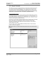
4.1.2 Using the Diagnostic Window in ProSoft Configuration Builder
To connect to the module’s Configuration/Debug serial port,
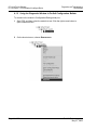
1
Start PCB, and then select the module to test. Click the right mouse button to
open a shortcut menu.
2
On the shortcut menu, choose DIAGNOSTICS.
Page 44 of 98
ProSoft Technology, Inc.
May 21, 2009
Diagnostics and Troubleshooting
Driver Manual
3
CC-Link ♦ ProLinx Gateway
CC-Link version 1.10 Local Station & Intelligent Device
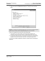
This action opens the DIAGNOSTICS dialog box. Press [?] to open the Main
Menu.
Important: The illustrations of configuration/debug menus in this section are intended as a general
guide, and may not exactly match the configuration/debug menus in your own module.
If there is no response from the module, follow these steps:
1
2
Verify that the null modem cable is connected properly between your
computer’s serial port and the module. A regular serial cable will not work.
On computers with more than one serial port, verify that your communication
program is connected to the same port that is connected to the module.
If you are still not able to establish a connection, contact ProSoft Technology for
assistance.
ProSoft Technology, Inc.
May 21, 2009
Page 45 of 98
CC-Link ♦ ProLinx Gateway
CC-Link version 1.10 Local Station & Intelligent Device
Diagnostics and Troubleshooting
Driver Manual
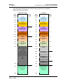
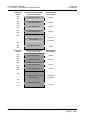
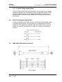
4.1.3 Navigation
All of the sub-menus for this module contain commands to redisplay the menu or
return to the previous menu. You can always return from a sub-menu to the next
higher menu by pressing [M] on your keyboard.
The organization of the menu structure is represented in simplified form in the
following illustration:
The remainder of this section shows you the menus available for this module,
and briefly discusses the commands available to you.
Keystrokes
The keyboard commands on these menus are almost always non-case sensitive.
You can enter most commands in lower case or capital letters.
The menus use a few special characters ([?], [-], [+], [@]) that must be entered
exactly as shown. Some of these characters will require you to use the [SHIFT],
[CTRL] or [ALT] keys to enter them correctly. For example, on US English
keyboards, enter the [?] command as [SHIFT][/].
Also, take care to distinguish capital letter [I] from lower case letter [L] (L) and
number [1]; likewise for capital letter [O] and number [0]. Although these
characters look nearly the same on the screen, they perform different actions on
the module.
Page 46 of 98
ProSoft Technology, Inc.
May 21, 2009
Diagnostics and Troubleshooting
Driver Manual
4.2
CC-Link ♦ ProLinx Gateway
CC-Link version 1.10 Local Station & Intelligent Device
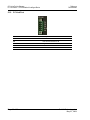
LED Indicators
4.2.1 Base Module LEDs
LED
State
Description
Power
Off
Power is not connected to the power terminals. This LED is hardware
driven, so it only requires power to operate.
Green Solid
Power is connected to the power terminals. Verify that the other LEDs
for operational and functional status.
Off
Normal operation.
Red Solid
A critical error has occurred. Program executable has failed or has
been user-terminated and is no longer running. Press Reset p/b or
cycle power to clear error. If not, use the Debug procedures described
later in this manual.
Off
Normal operation.
Amber Solid
The unit is in the configuration mode. The configuration file is being
read and the unit is implementing the configuration values and
initializing the hardware. This will occur during power cycle, or after
pressing the reset button. It also occurs after a cold/warm boot
command is received.
Off
Normal operation.
Flashing
An error condition has been detected and is occurring. Check
configuration.
Solid Red
This condition is indicative of a large number of errors in the application
interface communications. The module's error flag is cleared at the
start of each command (master/client) or receipt of data
(slave/adapter/server).
Fault
Cfg
Err
4.2.2 CC-Link Interface-Specific LEDs
LED
State
Description
RUN
Green
Indicates CC-Link hardware is operating normally
Off
Indicates a watchdog timer error/possible hardware failure
L RUN
Green
Indicates successful data link execution
L ERR
Red
Indicates a data link communication error
Flash
Indicates station number or mode changing during operation
Green
Indicates the gateway is sending CC-Link data
RD
Green
Indicates the gateway is receiving CC-Link data
ERR
Red
Indicates a switch setting error (L ERR also turns on)
SD
ProSoft Technology, Inc.
May 21, 2009
Master overlap
Parameter error
Communication error
Page 47 of 98
CC-Link ♦ ProLinx Gateway
CC-Link version 1.10 Local Station & Intelligent Device
4.3
Diagnostics and Troubleshooting
Driver Manual
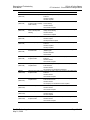
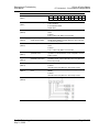
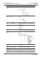
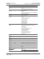
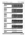
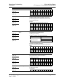
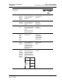
Status Data
No.
SB0000
(REG 0 bit0)
Name
Data link restart
SB0001
(REG 0 bit1)
Refresh instruction at standby
master switching
SB0002
(REG 0 bit2)
Data link stop
SB0004
(REG 0 bit4)
Temporary error invalid
request
SB0005
(REG 0 bit5)
Temporary error invalid cancel
request
SB0008
(REG 0 bit8)
Line test request
SB0009
(REG 0 bit9)
Parameter setting test request
SB000C
(REG 0 bit12)
Forced master switching
SB0010
(REG 1 bit0)
Number of retries clear
SB0011
(REG 1 bit1)
Number of transmission errors
clear
SB0014
(REG 1 bit4)
Transient transmission clear
SB0015
(REG 1 bit5)
Transient transmission
instruction
SB0040
(REG 4 bit0)
Data link restart acceptance
Page 48 of 98
Description
Restarts the data link stopped by SB0002.
OFF: No restart instruction
ON: Restart
Gives a refresh instruction of cyclic data after switching to the
standby master station.
OFF: No instruction
ON: Instruction
Stops the data link of the host. However, this function should be
executed carefully since execution of this function at the master
station will stop the whole system.
OFF: No stop instruction
ON: Stop instruction
Defines the station specified in SW0003 to SW0007 as a temporary
error invalid station.
OFF: No request
ON: Request
Cancels the station specified in SW0003 to SW0007 from a
temporary error invalid station.
OFF: No request
ON: Request
Performs a line test on the station specified in SW0008.
OFF: No request
ON: Request
Reads the parameter information of the actual system configuration
and sets it to the parameter setting test area.
OFF: No request
ON: Request
Forcibly shifts the master station function to the specified master
station.
OFF: No request
ON: Request
Clears the number of retries.
OFF: Reset not instructed
ON: Reset instructed
Clears the number of transmission errors.
OFF: Reset not instructed
ON: Reset instructed
Clears transient transmission errors.
OFF: Reset not instructed
ON: Reset instructed
Prohibits transient
OFF: Overwrite
ON: Hold
Indicates the acceptance status of the data link restart instruction.
OFF: Not accepted
ON: Start instruction accepted
ProSoft Technology, Inc.
May 21, 2009
Diagnostics and Troubleshooting
Driver Manual
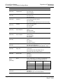
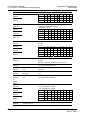
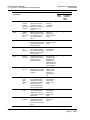
No.
SB0041
(REG 4 bit1)
SB0042
(REG 4 bit2)
SB0043
(REG 4 bit3)
SB0044
(REG 4 bit4)
SB0045
(REG 4 bit5)
SB0046
(REG 4 bit6)
SB0048
(REG 4 bit8)
SB0049
(REG 4 bit9)
SB004A
(REG 4 bit10)
SB004B
(REG 4 bit11)
SB004C
(REG 4 bit12)
SB004D
(REG 4 bit13)
SB004E
(REG 4 bit14)
CC-Link ♦ ProLinx Gateway
CC-Link version 1.10 Local Station & Intelligent Device
Name
Data link restart completed
Description
Indicates the acceptance completed status of the data link restart
instruction.
OFF: Not completed
ON: Start completed
Refresh instruction
Indicates the acceptance status of the refresh instruction at standby
acceptance status at standby master switching.
master switching
OFF: Not executed
ON: Instruction accepted
Refresh switching completed Indicates the execution completed status of the refresh switching at
standby master switching.
status at standby master
switching
OFF: Not executed
ON: Execution completed
Data link stop acceptance
Indicates the acceptance status of the data link stop instruction.
OFF: Not accepted
ON: Stop instruction accepted
Data link stop completed
Indicates the acceptance completed status of the data link stop
instruction.
OFF: Not completed
ON: Stop completed
Forced master switching
Indicates the executable status of the forced master switching
executable status
(SB000C) signal.
OFF: Not executable
ON: Executable
Temporary error invalid
Indicates the acceptance status of the temporary error invalid
acceptance status
instruction.
OFF: Not executed
ON: Instruction accepted
Temporary error invalid
Indicates the acceptance completed status of the temporary error
completed status
invalid instruction.
OFF: Not executed
ON: Temporary error invalid station determined
Temporary error invalid cancel Indicates the acceptance status of the temporary error invalid cancel
acceptance status
instruction.
OFF: Not executed
ON: Instruction accepted
Temporary error invalid cancel Indicates the acceptance completed status of the temporary error
completed status
invalid cancel instruction.
OFF: Not executed
ON: Temporary error invalid station cancel completed
Line test acceptance status
Indicates the acceptance status of the line test request.
OFF: Not executed
ON: Instruction accepted
Line test completed status
Indicates the completed status of the line test.
OFF: Not executed
ON: Test completed
Parameter setting test
Indicates the acceptance status of the parameter setting test request.
acceptance status
OFF: Not executed
ON: Instruction accepted
ProSoft Technology, Inc.
May 21, 2009
Page 49 of 98
CC-Link ♦ ProLinx Gateway
CC-Link version 1.10 Local Station & Intelligent Device
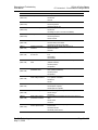
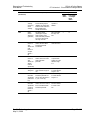
No.
SB004F
(REG 4 bit15)
SB0050
(REG 5 bit0)
SB005A
(REG 5 bit10)
SB005B
(REG 5 bit11)
SB005C
(REG 5 bit12)
SB005D
(REG 5 bit13)
SB0060
(REG 6 bit0)
SB0061
(REG 6 bit1)
SB0062
(REG 6 bit2)
SB0065
(REG 6 bit5)
SB0066
SB0067
(REG 6 bit6,7)
SB006A
(REG 6 bit10)
Page 50 of 98
Diagnostics and Troubleshooting
Driver Manual
Name
Parameter setting test
completed status
Description
Indicates the completed status of the parameter setting test.
OFF: Not executed
ON: Test completed
Offline test status
Indicates the execution status of the offline test.
OFF: Not executed
ON: During execution
Master switching request
Indicates the standby master station’s acceptance status of the
acceptance
master switching request from the line.
OFF: Not accepted
ON: Instruction accepted (Switching request from the line accepted)
Master switching request
Indicates the switching completed status of the standby master
completed
station as the master station.
OFF: Not completed
ON: Completed
Forced master switching
Indicates the acceptance status of the forced master switching
request acceptance
request.
OFF: Not accepted
ON: Instruction accepted
Forced master switching
Indicates the acceptance completed status of the forced master
request completed
switching request.
OFF: Not completed
ON: Completed
Host mode
Indicates the setting status of the mode setting switch of the host
gateway.
OFF: Online (0)
ON: Other than online (0)
Host type
Indicates the station type of the host gateway currently operating.
OFF: Master station (Station No. 0)
ON: Local station, intelligent device station (Station No. 1 to 64)
Host standby master station Indicates whether standby master station setting has been made or
setting status
not to the host.
OFF: No standby master station setting to the host
ON: Standby master station setting to the host
Input data status of host data Indicates the "data link error station’s input data status" setting status
link error station
of the host.
OFF: Cleared
ON: Retained
Number of stations occupied Indicates the setting status of the switch information 4, 5 "Number of
by host
stations occupied by host". This setting is as indicated below
depending on the combination of the switch information 4, 5.
Number of occupied Switch information 4 Switch information
stations
5
1 station occupied
OFF
OFF
2 station occupied
OFF
ON
3 station occupied
ON
ON
4 station occupied
ON
OFF
Switch setting status
Indicates the setting status of the switches, etc.
OFF: Normal
ON: Setting error (Error code stored into SW006A)
ProSoft Technology, Inc.
May 21, 2009
Diagnostics and Troubleshooting
Driver Manual
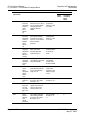
No.
SB006B
(REG 6 bit11)
SB006C
(REG 6 bit12)
SB006D
(REG 6 bit13)
SB006E
(REG 6 bit14)
SB0070
(REG 7 bit0)
SB0071
(REG 7 bit1)
SB0073
(REG 7 bit3)
SB0074
(REG 7 bit4)
SB0075
(REG 7 bit5)
SB0076
(REG 7 bit6)
SB0077
(REG 7 bit7)
SB0078
(REG 7 bit8)
SB0079
(REG 7 bit9)
SB007B
(REG 7 bit11)
CC-Link ♦ ProLinx Gateway
CC-Link version 1.10 Local Station & Intelligent Device
Name
Host operation status
Description
Indicates the operation status of the host.
OFF: Normal
ON: Error
Link status
Indicates the data link status of the host.
OFF: During data link
ON: During data link stop
Parameter setting status
Indicates the parameter setting status.
OFF: Normal
ON: Setting error (Error code stored into SW0068)
Host operation status
Indicates the operation status of the host data link.
OFF: During execution
ON: Not executed
Master station information
Indicates the data link status.
OFF: Data link by master station
ON: Data link by standby master station
Standby master station
Whether the standby master station exists or not
information
OFF: Does not exist
ON: Exists
Operation specification status Indicates the parameter-based operation specification status at driver
at driver error
error.
OFF: Stopped
ON: Continued
Reserved station specification Indicates the parameter-based reserved station specification status.
status
(SW0074 to SW0077)
OFF: Not specified
ON: Specified
Error invalid station
Indicates the parameter-based error invalid station specification
specification status
status. (SW0078 to SW007B)
OFF: Not specified
ON: Specified
Temporary error invalid
Indicates whether the temporary error invalid stations have been set
station setting information
or not. (SW007C to SW007F)
OFF: Not set
ON: Set
Parameter reception status
Indicates the parameter reception status from the master station.
OFF: Reception completed
ON: Reception not completed
Host switch change detection Detects the setting switch change of the host during data link.
OFF: No change
ON: Change
Master station returning
Indicates whether the parameter has been set to no return or a
specification information
return.
OFF: No return
ON: Return
Host master/standby master Indicates whether the host is operating as the master or standby
function operation status
master function.
OFF: Master function
ON: Standby master function
ProSoft Technology, Inc.
May 21, 2009
Page 51 of 98
CC-Link ♦ ProLinx Gateway
CC-Link version 1.10 Local Station & Intelligent Device
No.
SB0080
(REG 8 bit0)
SB0081
(REG 8 bit1)
SB0082
(REG 8 bit2)
SB0083
(REG 8 bit3)
SB0090
(REG 9 bit0)
SB0091
(REG 9 bit1)
SB0094
(REG 9 bit4)
SB0095
(REG 9 bit5)
SB00AC
(REG 10 bit12)
SB00B4
(REG 11 bit4)
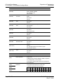
No.
SW0003
(REG 1)
SW0004
(REG 2)
SW0005
(REG 3)
SW0006
(REG 4)
Page 52 of 98
Diagnostics and Troubleshooting
Driver Manual
Name
Other station data link status
Description
Indicates the communication status with the remote stations/local
stations. (SW0080 to SW0083)
OFF: All stations normal
ON: Error station
Other station watch dog timer Indicates the watch dog timer error occurrence status at the other
error status
stations.
OFF: No error
ON: Error
Other station fuse blown
Indicates the fuse blown occurrence status at other stations.
status
OFF: No error
ON: Error
Other station switch change Detects the setting switch changes of other stations during data link.
status
OFF: No change
ON: Change
Host line status
Indicates the line status.
OFF: Normal
ON: Error (Wire break)
Transmission status
Indicates the transmission status of the line.
OFF: Normal
ON: Error
Transient transmission status Indicates whether a transient transmission error occurred or not.
OFF: No error
ON: Error
Master station transient
Indicates the master station transient transmission status.
transmission status
OFF: Normal
ON: Error
Other station parameter status Other station parameter communication status (SW00AC to
SW00AF)
OFF: Other than parameter communication in progress
ON: Parameters requested
Standby master station test
The test result of Line test 1/Line test 2 is stored.
result
OFF: Normal
ON: Error
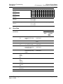
Name
Description
Multiple temporary error invalid Selects whether multiple temporary error invalid stations will be
stations specification
specified or not.
00: Multiple stations indicated in SW0004 to SW0007 are specified.
01 to 64: Single station 1 to 64 is specified.
(For the numeral, specify the station number set as the temporary
error invalid station.)
Temporary error invalid station Specifies the temporary error invalid station.
specification
0: Not specified as the temporary error invalid station.
1: Specified as the temporary error invalid station.
bF
bE bD bC
b3
b2
b1
b0
SW004 16
15
14
13
to 4
3
2
1
SW005 32
31
30
29
to 20
19
18
17
ProSoft Technology, Inc.
May 21, 2009
Diagnostics and Troubleshooting
Driver Manual
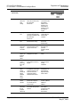
No.
SW0007
(REG 5)
SW0008
(REG 6)
SW0041
(REG 63)
SW0043
(REG 65)
SW0045
(REG 67)
SW0049
(REG 71)
SW004B
(REG 73)
SW004D
(REG 75)
SW004F
(REG 77)
SW0058
(REG 86)
CC-Link ♦ ProLinx Gateway
CC-Link version 1.10 Local Station & Intelligent Device
Name
Description
SW006 48
47
46
45
to 36
35
34
33
SW007 64
63
62
61
to 52
51
50
49
1 to 64 in the table indicates the station numbers.
Line-tested station setting
Sets the station on which the line test will be performed. 0: Whole
system (all stations)
01 to 64: Specified station
Default value: 0
Data link restart result
The execution result of the data link restart instruction by SB0000 is
stored.
0: Normal
From 1 on: Error code (Refer to 4.1 Error Codes)
Refresh switching result at
Indicates the execution result of refresh switching at specified
standby master switching
standby master switching. 0: Normal Other than 0: Error code (refer
to 4.1 Error Codes) is stored.
Data link stop result
The execution result of the data link stop instruction by SB0002 is
stored.
0: Normal
From 1 on: Error code (Refer to 4.1 Error Codes)
Temporary error invalid station Indicates the execution result of the temporary error invalid station
specification result
specification. 0: Normal Other than 0: Error code (Refer to 4.1 Error
Codes) is stored.
Temporary error invalid station Indicates the execution result of the temporary error invalid station
specification cancel result
specification cancel. 0: Normal Other than 0: Error code (Refer to 4.1
Error Codes) is stored.
Line test result
Indicates the execution result of the line test.
0: Normal
Other than 0: Error code (Refer to 4.1 Error Codes) is stored.
Parameter setting test request Indicates the execution result of the parameter setting test request by
result
SB0009.
0: Normal
Other than 0: Error code (Refer to 4.1 Error Codes) is stored.
Interface board status
The interface board status is stored.
ProSoft Technology, Inc.
May 21, 2009
Page 53 of 98
CC-Link ♦ ProLinx Gateway
CC-Link version 1.10 Local Station & Intelligent Device
Diagnostics and Troubleshooting
Driver Manual
No.
SW0059
(REG 87)
Name
Transmission speed setting *
Description
The baud rate setting is stored.
SW005A
(REG 88)
Built-in board switch setting
status *
The switch setting of the built-in board is stored.
0: OFF
1: ON
SW005D
(REG 91)
Forced master switching
instruction result
SW0060
(REG 94)
Mode setting status *
SW0061
(REG 95)
SW0062
(REG 96)
Host station No. *
The execution result of the forced master switching instruction by
SB000C is stored. 0: Normal From 1 on: Error code (Refer to 4.1
Error Codes)
The mode setting status is stored.
0: Online 2: Offline
3: Line test 1
4: Line test 2
6: Hardware test
The currently operating host station number is stored.
0: Master station 1 to 64: Local station, intelligent device station
The operation setting status is stored.
0: OFF
1: ON
SW0064
(REG 98)
SW0065
(REG 99)
SW0066
(REG 100)
SW0067
(REG 101)
Number of retries information
Page 54 of 98
Operation setting status
Indicates the number of retries setting information at error response.
1 to 7 (retries)
Number of automatic returning Indicates the number of automatic returning stations setting
stations information
information during 1 link scan. 1 to 10 (stations)
Delay timer information
Indicates the scan interval delay time setting information.
Parameter information
The parameter information area is stored. Fixed to 0: Parameter
startup
ProSoft Technology, Inc.
May 21, 2009
Diagnostics and Troubleshooting
Driver Manual
CC-Link ♦ ProLinx Gateway
CC-Link version 1.10 Local Station & Intelligent Device
No.
SW0068
(REG 102)
Name
Host parameter status
SW0069
(REG 103)
Loading status
SW006A
(REG 104)
SW006B
(REG 105)
Switch setting status
SW006C
(REG 106)
Host data link status
SW006D
(REG 107)
SW006E
(REG 108)
SW006F
(REG 109)
SW0070
(REG 110)
SW0071
(REG 111)
SW0072
(REG 112)
SW0073
(REG 113)
SW0074
(REG 114)
SW0075
(REG 115)
Maximum link scan time
The host operation status is stored.
0: Normal
1: Transmission path error detection
2: Parameter error detection
3: CRC error detection
4: Time-out error detection
5: Abort error detection
6: Setting error detection
7: Other error detection
The host data link status is stored. 0: Initial status
1: Parameter reception waiting status (local station only)
2: During data link
3: During data link stop
4: During disconnection (no polling request)
5: During disconnection (line error)
6: During disconnection (other)
7: During line test execution
8: During parameter setting test execution
9: During automatic return processing
FF: During reset
The maximum value of link scan time is stored. (1ms unit)
Present link scan time
The present value of link scan time is stored. (1ms unit)
Minimum link scan time
The minimum value of link scan time is stored. (1ms unit)
Total number of stations
The last station number set in the parameter is stored. Station 1 to 64
Host operation status
Description
The parameter setting status is stored.
0: Normal
From 1 on: Error code (Refer to 4.1 Error Code)
The station number duplication and parameter consistency of each
gateway are stored.
0: Normal
From 1 on: Error code (Refer to 4.1 Error Code). Details are stored
into SW0098-9B and SW009C-9F.
The switch setting status is stored. 0: Normal From 1 on: Error code
(Refer to 4.1 Error Code)
Highest communicating station The highest station number (station number of the station number
number
setting switch) that is executing data link is stored. Station 1 to 64
Number of connected stations
The number of stations that are executing data link is stored.
Standby master station No.
The station number of the standby master station is stored. 1 to 64
(Station)
Reserved station specification
status *1
The reserved station setting status is stored. 0: Other than reserved
station
1: Reserved station
bF bE bD bC
b3 b2 b1 b0
ProSoft Technology, Inc.
May 21, 2009
Page 55 of 98
CC-Link ♦ ProLinx Gateway
CC-Link version 1.10 Local Station & Intelligent Device
No.
SW0076
(REG 116)
SW0077
(REG 117)
Name
SW0078
(REG 118)
SW0079
(REG 119)
SW007A
(REG 120)
SW007B
(REG 121)
Error invalid station
specification status
SW007C
(REG 122)
SW007D
(REG 123)
SW007E
(REG 124)
SW007F
(REG 125)
Temporary error invalid status
SW0080
(REG 126)
SW0081
(REG 127)
SW0082
(REG 128)
SW0083
(REG 129)
Other station data link status
SW0084
(REG 130)
SW0085
(REG 131)
SW0086
(REG 132)
SW0087
(REG 133)
Other station watch dog timer
error occurrence status
SW0090
(REG 142)
Line status
SW0094
(REG 146)
SW0095
(REG 147)
Transient transmission status
Page 56 of 98
Diagnostics and Troubleshooting
Driver Manual
Description
SW074 16 15
14
13
to 4
3
2
SW075 32 31
30
29
to 20 19 18
SW076 48 47
46
45
to 36 35 34
SW077 64 63
62
61
to 52 51 50
1 to 64 in the table indicates the station numbers.
Indicates the temporary error invalid status.
0: Normal status
1: Temporary error invalid status
bF bE bD bC
b3 b2 b1
SW078 16 15
14
13
to 4
3
2
SW079 32 31
30
29
to 20 19 18
SW07A 48 47
46
45
to 36 35 34
SW07B 64 63
62
61
to 52 51 50
1 to 64 in the table indicates the station numbers.
The error invalid station setting status is stored.
0: Other than error invalid station
1: Error invalid station
bF bE bD bC
b3 b2 b1
SW07C 16 15
14
13
to 4
3
2
SW07D 32 31
30
29
to 20 19 18
SW07E 48 47
46
45
to 36 35 34
SW07F 64 63
62
61
to 52 51 50
1 to 64 in the table indicates the station numbers.
The data link status of each station is stored.
0: Normal
1: Data link error occurrence
bF bE bD bC
b3 b2 b1
SW080 16 15
14
13
to 4
3
2
SW081 32 31
30
29
to 20 19 18
SW082 48 47
46
45
to 36 35 34
SW083 64 63
62
61
to 52 51 50
1 to 64 in the table indicates the station numbers.
Indicates the watch dog timer error occurrence status.
0: No watch dog timer error
1: Watch dog timer error
bF bE bD bC
b3 b2 b1
SW088 16 15
14
13
to 4
3
2
SW089 32 31
30
29
to 20 19 18
SW08A 48 47
46
45
to 36 35 34
SW08B 64 63
62
61
to 52 51 50
1 to 64 in the table indicates the station numbers.
The line status is stored.
0: Normal
1: Data link disable (wire break)
Indicates the transient transmission error occurrence status.
0: No transient transmission error
1: Transient transmission error
bF bE bD bC
b3 b2 b1
1
17
33
49
b0
1
17
33
49
b0
1
17
33
49
b0
1
17
33
49
b0
1
17
33
49
b0
ProSoft Technology, Inc.
May 21, 2009
Diagnostics and Troubleshooting
Driver Manual
No.
SW0096
(REG 148)
SW0097
(REG 149)
SW0098
(REG 150)
SW0099
(REG 151)
SW009A
(REG 152)
SW009B
(REG 153)
SW009C
(REG 154)
SW009D
(REG 155)
SW009E
(REG 156)
SW009F
(REG 157)
SW00A0
(REG 158)
SW00A1
(REG 159)
SW00A2
(REG 160)
SW00A3
(REG 161)
SW00A8
(REG 166)
SW00A9
(REG 167)
CC-Link ♦ ProLinx Gateway
CC-Link version 1.10 Local Station & Intelligent Device
Name
Description
SW094 16 15
14
13
to 4
3
2
1
SW095 32 31
30
29
to 20 19 18 17
SW096 48 47
46
45
to 36 35 34 33
SW097 64 63
62
61
to 52 51 50 49
1 to 64 in the table indicates the station numbers.
Station No. duplication status If the occupied station number of the slave station duplications with
the next slave station number, the duplication status is stored.
This does not apply to the case where the head station numbers
duplication with each other.
0: Normal
1: Station number duplication (head station number only)
bF bE bD bC
b3 b2 b1 b0
SW098 16 15
14
13
to 4
3
2
1
SW099 32 31
30
29
to 20 19 18 17
SW09A 48 47
46
45
to 36 35 34 33
SW09B 64 63
62
61
to 52 51 50 49
1 to 64 in the table indicates the station numbers.
Loading/parameter consistency The consistency status, such as CC-Link version difference, between
status
the parameters and slave stations is stored.
1) Station type inconsistency
(except the combination of the following station types)
Loading
Parameter
Remote device station
Remote I/O station
Remote I/O station
Intelligent device station
Remote device station
2) Number of occupied stations inconsistency (loading > parameter)
3) Expanded cyclic setting inconsistency
4) Version inconsistency between parameter and loaded remote
station
bF bE bD bC
b3 b2 b1 b0
SW09C 16 15
14
13
to 4
3
2
1
SW09D 32 31
30
29
to 20 19 18 17
SW09E 48 47
46
45
to 36 35 34 33
SW09F 64 63
62
61
to 52 51 50 49
1 to 64 in the table indicates the station numbers.
Station Type (1)
Indicates the station type of each station in bit units.
0: Remote I/O stations or remote device stations
1: Intelligent device stations
bF bE bD bC
b3 b2 b1 b0
SW0A0 16 15
14
13
~ 4
3
2
1
SW0A1 32 31
30
29
~ 20 19 18 17
SW0A2 48 47
46
45
~ 36 35 34 33
SW0A3 64 63
62
61
~ 52 51 50 49
1 to 64 in the table indicates the station numbers.
Station setting information
Indicates the head station of each station in bits.
0: Other than head station
1: Head station
bF bE bD bC
b3 b2 b1 b0
ProSoft Technology, Inc.
May 21, 2009
Page 57 of 98
CC-Link ♦ ProLinx Gateway
CC-Link version 1.10 Local Station & Intelligent Device
No.
SW00AA
(REG 168)
SW00AB
(REG 169)
SW00AC
(REG 170)
SW00AD
(REG 171)
SW00AE
(REG 172)
SW00AF
(REG 173)
SW00B4
(REG 178)
SW00B5
(REG 179)
SW00B6
(REG 180)
SW00B7
(REG 181)
SW00B8
(REG 182)
SW00C0
(REG 190)
SW00E1
(REG 203)
SW00E2
(REG 204)
SW00E3
(REG 205)
To
SW00FF
(REG 253)
SW0140
(REG 318)
SW141
(REG 319)
SW142
(REG 320)
SW0143
(REG 321)
SW0144
(REG 322)
Page 58 of 98
Diagnostics and Troubleshooting
Driver Manual
Name
Description
SW08C 16 15
14
13
~ 4
3
2
SW08D 32 31
30
29
~ 20 19 18
SW08E 48 47
46
45
~ 36 35 34
SW08F 64 63
62
61
~ 52 51 50
1 to 64 in the table indicates the station numbers.
Other station parameter status Indicates the parameter status of each station in bit units.
0: Other than communication in progress
1: Parameters requested
bF bE bD bC
b3 b2 b1
SW0A8
16 15 14
13
~ 4
3
2
SW08A9 32 31 30
29
~ 20 19 18
SW0AA
48 47 46
45
~ 36 35 34
SW0AB
64 63 62
61
~ 52 51 50
1 to 64 in the table indicates the station numbers.
Line test 1 result
The test result of Line test 1 is stored.
0: Normal
1: Error
bF bE bD bC
b3 b2 b1
SW0B4 16 15
14
13
to 4
3
2
SW0B5 32 31
30
29
to 20 19 18
SW0B6 48 47
46
45
to 36 35 34
SW0B7 64 63
62
61
to 52 51 50
1 to 64 in the table indicates the station numbers.
Line test result
Stores the line test result.
0: Normal
Other than 0: Error code (See Section 4.1, "Error Codes.")
Retry count
Stores the retry execution count.
0 or more: Accumulated retry count
Transient transmission error
Stores the number of errors that occurred during transient
count
transmission.
1
17
33
49
b0
1
17
33
49
b0
1
17
33
49
Transient transmission error
data pointer
Stores the next pointer for setting the transient transmission error
code.
Transient transmission error
code
Stores the error code that occurred during transient transmission. (29
areas) Storage method: Ring buffer
Station type (2)
Indicates whether the remote station is Ver. 2 compatible.
0: Ver. 1 compatible remote station.
1: Ver. 2 compatible remote station
bF bE bD bC
b3 b2 b1
SW0140 16 15 14
13
to 4
3
2
SW0141 32 31 30
29
to 20 19 18
SW0142 48 47 46
45
to 36 35 34
SW0143 64 63 62
61
to 52 51 50
1 to 64 in the table indicates the station numbers.
b0
1
17
33
49
Mounting/Parameter
consistency status (2)
ProSoft Technology, Inc.
May 21, 2009
Diagnostics and Troubleshooting
Driver Manual
4.4
CC-Link ♦ ProLinx Gateway
CC-Link version 1.10 Local Station & Intelligent Device
No.
SW0145
(REG 323)
SW0146
(REG 324)
SW0147
(REG 325)
SW148
(REG 326)
Name
Description
SW149
(REG 327)
Host parameter mode
Parameter mode
bF bE bD bC
b3 b2
SW0144 16 15 14
13
to 4
3
SW0145 32 31 30
29
to 20 19
SW0146 48 47 46
45
to 36 35
SW0147 64 63 62
61
to 52 51
1 to 64 in the table indicates the station numbers.
Indicates the mode used in the network.
0: Ver. 1 mode
2: Ver. 2 mode
Indicates the mode in which the host station is operating.
0: Ver. 1 mode
2: Ver. 2 mode
b1
2
18
34
50
b0
1
17
33
49
Error Data
Error Code
(Hexadecimal)
Error
Error Cause (Details)
B002
Link stop
error
Link stop was implemented
when the link was already
stopped.
B102
Link error
B103
Corrective Action
Detectability
Master
Station
Local Station
or Intelligent
Device
Station
Change the
interface board.
Y
N
A line error has occurred.
Check the interface
board.
Y
Y
Setting value
error
The setting value of the
macro function is invalid.
Change the
interface board.
Y
N
B104
Start error
Link startup was
implemented when the link
was already started.
Change the
interface board.
Y
N
B105
Stop error
Link stop was implemented
when the link was already
stopped.
Change the
interface board.
Y
N
B110
Unable to
receive
transient
data
A line error has occurred.
Check the line.
Y
Y
B111
Transient
data
receiving
order error
A line error has occurred.
Check the line.
Y
Y
B112
Transient
data length
error
A line error has occurred.
Check the line.
Y
Y
B113
Transient
data ID error
A line error has occurred.
Check the line.
Y
Y
B115
Link error
A line error has occurred.
Check the line.
Y
Y
ProSoft Technology, Inc.
May 21, 2009
Page 59 of 98
CC-Link ♦ ProLinx Gateway
CC-Link version 1.10 Local Station & Intelligent Device
Error Code
(Hexadecimal)
Error
Error Cause (Details)
B201
Relevant
station error
when
sending
A data link error has occurred
at the relevant station at the
time of transient
transmission.
B202
Data length
error
B203
Diagnostics and Troubleshooting
Driver Manual
Corrective Action
Detectability
Master
Station
Local Station
or Intelligent
Device
Station
Check the status of
communication with
other stations,
whether or not a
temporary error
invalid station is
specified, or if the
host station is
stopped.
Y
Y
A line error may have
occurred if improper packet
data length is identified at the
time of transient
transmission.
Check the line. Set
a data length that
fulfills required
conditions.
Y
Y
CT value
error
The CT value in the CC-Link
transient frame is wrong.
Check the value in
the CC-Link
transient frame.
Y
Y
B204
Failed to
ensure error
response
send buffer
The buffer area could not be
ensured at the time of error
response transmission.
Wait a while and
then retransmit.
(Transient
operation overload
status)
Y
Y
B205
Target
station is not
intelligent
device
station
The target station was not an
intelligent device station.
Check the target
station.
Y
Y
B301
Unable to
request
processing
due to link
stop
A line test request was
issued while the data link is
stopped.
Perform a line test
while the data link
is being
established.
Y
Y
B302
Specified
station
number
exceeds the
highest
allowable
station
number
The station number specified
for a temporary error invalid
request or temporary error
invalid cancel request
exceeded the highest
allowable station number.
Specify a station
number that is not
greater than the
highest allowable
station number.
Y
N
B303
No station
number
specified
No station number is
specified for a temporary
error invalid request or
cancel request.
Specify any station
numbers. (SW0003,
SW0004 to
SW0007)
Y
N
B304
Error station
detected by
line test
(reception
status error)
An error was detected in a
slave station during line test
execution.
Check that the
slave station is
operational and that
the cable is not
disconnected.
Y
N
Page 60 of 98
ProSoft Technology, Inc.
May 21, 2009
Diagnostics and Troubleshooting
Driver Manual
CC-Link ♦ ProLinx Gateway
CC-Link version 1.10 Local Station & Intelligent Device
Error Code
(Hexadecimal)
Error
Error Cause (Details)
B305
Error station
detected by
line test
(response
data error)
An error was detected in the
response data looped back
as a result of line test
execution.
B306
Specified
station is not
head station
B307
All stations
faulty
Corrective Action
Detectability
Master
Station
Local Station
or Intelligent
Device
Station
Replace the slave
station subjected to
the line test.
Y
N
A station other than the head
station was specified for the
temporary error invalid
request.
Specify a head
station for the
temporary error
invalid request.
Y
N
All stations were in a data
link error state when either of
the following requests was
issued:
Request again after
the data link
becomes normal.
Y
Y
SB0000 (data link restart)
SB0002 (data link stop)
B308
Total
number of
slave
stations
(station
number
error)
The station number is outside
the range 1 to 64.
Check the station
numbers of the
mounted gateways
for any duplication
(including occupied
station numbers).
Y
N
B309
Station
number
duplication
The station number of the
connected gateway was
duplicated (including
occupied station numbers).
Note that this excludes
duplication of the head
station number.
Check the
gateways’ station
numbers.
Y
N
Inconsistenc
y between
connected
gateway and
parameter
(connected
gateway >
parameter)
The station types of the
gateway are different from
those set as parameters, or
the number of occupied
stations of the gateway is
greater than the parameter.
Example:
Set correct
parameters.
Y
N
Connected
gateway
Parameter
Setting
Remote
device
Remote
I/O
Intelligent
device
Remote
I/O
Remote
device
ProSoft Technology, Inc.
May 21, 2009
Page 61 of 98
CC-Link ♦ ProLinx Gateway
CC-Link version 1.10 Local Station & Intelligent Device
Error Code
(Hexadecimal)
Error
Error Cause (Details)
B30B
Inconsistenc
y between
connected
gateway and
parameter
The mounting state does not
match the corresponding
parameters. (A station,
whose station number is set
as a parameter, is not
mounted.)
B30C
Switching
station
specification
error
B30D
Diagnostics and Troubleshooting
Driver Manual
Corrective Action
Detectability
Master
Station
Local Station
or Intelligent
Device
Station
Match the mounting
status with
corresponding
parameters.
Y
N
SB0001 was turned ON in
other than the master station
or a system that does not
have a standby master
station.
Check if the
standby master
station exists in the
system.
Y
Y
Initial status
Temporary error invalid
station specification and SB
requests were issued before
starting the data link.
Issue the requests
after the data link is
started.
Y
N
B30E
Local station
not
supported
The execution of the function,
which is started by SB/SW
and executable at the master
station only, was attempted
at the local station.
Execute the
function from the
master station.
N
Y
B310
Data link
restart error
A data link restart request
(SB0000) was executed for
the station that was
performing a data link.
Execute the data
link restart request
(SB0000) for the
station that has
stopped a data link
with a data link stop
request (SB0002).
Y
Y
B311
Data link
stop error
A data link stop request
(SB0002) was executed for
the station that had stopped
a data link.
Execute the data
link stop request
(SB0002) for the
station that is
performing a data
link.
Y
Y
B312
Standby
master
station
absence
error
A forced master to standby
master switching request
(SB000C) was issued in a
system where no standby
master station exists or
where the standby master
station had become faulty.
Execute the request
after starting the
data link of the
standby master
station.
Y
N
B313
All stations
faulty
A forced master to standby
master switching request
(SB000C) was issued in a
system where all stations had
become faulty.
Execute the request
after starting the
data link of the
standby master
station.
Y
N
B314
Switching
target error
A forced master to standby
master switching request
(SB000C) was issued to a
station other than the master
station.
Execute the request
to the master
station.
N
Y
Page 62 of 98
ProSoft Technology, Inc.
May 21, 2009
Diagnostics and Troubleshooting
Driver Manual
CC-Link ♦ ProLinx Gateway
CC-Link version 1.10 Local Station & Intelligent Device
Error Code
(Hexadecimal)
Error
Error Cause (Details)
B315
Forced
switching
error during
master
switching
A forced master to standby
master switching request
(SB000C) was issued again
while the master station was
being switched to the
standby master station.
B384
Station
number
setting error
(parameter)
B385
Corrective Action
Detectability
Master
Station
Local Station
or Intelligent
Device
Station
Check the ON/OFF
operation of
SB000C.
Y
N
The station number
(including the occupied
station numbers) of the
station information parameter
was set to a value outside
the range 1H to 40H.
Set a value within
the range 1H to
40H.
Y
N
Total
number of
slave
stations error
(total
number of
occupied
stations >
64)
The total number of occupied
stations set in the station
information parameter
exceeded 64.
Set a parameter
value of 64 or less.
Y
N
B386
Total
number of
slave
stations (all
stations
reserved
specification)
All the numbers of occupied
stations were set to 0 in the
station information
parameter.
Set each of the
occupied station
numbers to a value
within the range 1
to 4.
Y
N
B387
Delay timer
setting error
The delay timer was set to a
value outside the range 0 to
100.
Set the delay timer
to a value within the
range 0 to 100.
Y
Y
B388
Station
information
specification
(other than 0
to 3)
The station type in the station
information parameter was
set to a value other than 0 to
3. (Ver. 1 mode only)
Set the station type
to a value within the
range 0 to 3.
Y
N
B38A
Station
information
specification
(number of
remote I/O
stations >
64)
The number of remote I/O
stations was set to a value of
65 or more with the station
information parameter.
Set the number of
remote I/O stations
to a value of 64 or
less.
Y
N
ProSoft Technology, Inc.
May 21, 2009
Page 63 of 98
CC-Link ♦ ProLinx Gateway
CC-Link version 1.10 Local Station & Intelligent Device
Error Code
(Hexadecimal)
Error
Error Cause (Details)
B38B
Station
information
specification
(number of
remote
device
stations >
42)
The number of remote device
stations was set to a value of
43 or more with the station
information parameter
(addresses 0440H to
04BEH).
B38C
Station
information
specification
(number of
intelligent
device
stations >
26)
B38E
Diagnostics and Troubleshooting
Driver Manual
Corrective Action
Detectability
Master
Station
Local Station
or Intelligent
Device
Station
Set the number of
remote device
stations to a value
of 42 or less.
Y
N
The number of intelligent
device stations (including
local stations) was set to a
value of 27 or more with the
station information
parameter.
Set the number of
intelligent device
stations to a value
of 26 or less.
Y
N
Buffer
assignment
specification
(transfer
data size >
4k words)
The total size of the transfer
buffers in the station
information parameter
exceeded 4k words.
Set the total size of
the transfer buffers
to less than 4k
words.
Y
Y
B38F
Buffer
assignment
specification
(unused
area)
Writing was performed to a
use prohibited (unused) area
of the dual port RAM.
Do not write to the
use prohibited
(unused) area of
the dual port RAM.
Y
Y
B390
Standby
master
station
specification
(station
number
error)
The standby master station
specification parameter was
set to a value outside the
range of 0 to 64.
Specify the standby
master station
number to a value
within the range of
0 to 64.
Y
Y
B391
Retry count
(other than 1
to 7)
The retry count parameter
was set to a value outside
the range of 1 to 7.
Set a value within
the range of 1 to 7.
Y
N
B392
Specification
in the event
of a driver
error (other
than 0 and
1)
The parameter specifying the
operation in the event of a
driver error was set to a
value other than 0 and 1.
Set 0 or 1.
Y
N
B394
Invalid
number of
automatic
return
stations
(parameter)
The "number of automatic
return stations" parameter
was set to a value outside
the range of 1 to 10.
Set a value within
the range of 1 to
10.
Y
N
Page 64 of 98
ProSoft Technology, Inc.
May 21, 2009
Diagnostics and Troubleshooting
Driver Manual
CC-Link ♦ ProLinx Gateway
CC-Link version 1.10 Local Station & Intelligent Device
Error Code
(Hexadecimal)
Error
Error Cause (Details)
B396
Duplicate
station
number error
(parameter)
A duplicate station number
was specified with the station
information parameter.
B397
Station
information
setting error
(parameter)
The station information
parameter setting does not
meet the following condition:
(16 x A) + (54 x B) + (88 x C)
≤2304
Corrective Action
Detectability
Master
Station
Local Station
or Intelligent
Device
Station
Set parameters
correctly so that no
station numbers are
duplicated.
Y
N
Set the parameter
so that it meets the
condition shown on
the left.
Y
N
A: Number of remote I/O
stations
B: Number of remote device
stations
C: Number of intelligent
device stations (including
local stations)
B398
Invalid
number of
occupied
stations
(parameter)
The number of occupied
stations in the station
information parameter
(addresses 0220H to 025F)
was set to a value outside
the range of 1 to 4.
Set a value within
the range from 1 to
4.
Y
N
B399
Invalid
number of
connected
gateways
(parameter)
The "number of connected
gateways" parameter was set
to a value outside the range
of 1 to 64.
Set a value within
the range of 1 to
64.
Y
N
B39A
Standby
master
station
specification
(different
from host
station
number)
The "standby master station
number" set to the master
station is different from the
actual station number of the
standby master station, or it
is a local station number.
Change the
parameter setting of
the master station,
or change the
station number
setting of the
local/standby
master station, and
then reset the
system.
N
Y
B39B
All stations
reserved
setting
All stations were set as
reserved stations.
Check the reserved
station settings.
Y
N
ProSoft Technology, Inc.
May 21, 2009
Page 65 of 98
CC-Link ♦ ProLinx Gateway
CC-Link version 1.10 Local Station & Intelligent Device
Error Code
(Hexadecimal)
Error
Error Cause (Details)
B39C
Station type
when
standby
master
station is
specified
Ver. 1 mode:
Other than 2
and 3 Ver. 2
mode: Other
than 6, 9, C
and F
Any other than "intelligent
device station" is set in the
station type in the slave
station setting of the station
set as the standby master
station. Or, the mode of the
master station is different
from the one set in the
standby master station
specification.
B39E
8-/16-point
setting illegal
B3A0
Mode illegal
(master/local
stations)
Diagnostics and Troubleshooting
Driver Manual
Corrective Action
Detectability
Master
Station
Local Station
or Intelligent
Device
Station
Specify the standby
master station as
an intelligent device
station.
Y
N
A setting of 8-point I/O
station or 16-point I/O station
has been made for a station
other than the remote I/O
station.
Configure an 8point/16-point
setting for the
remote I/O station.
Y
N
A model illegal error has
occurred between the master
and the local or standby
master station.
After setting the
master station
parameter or local
or standby master
station parameter
again, reset the
system.
N
Y
The mode differs between
the master and standby
master stations.
The local station is in the Ver.
2/additional mode while the
master station is in the Ver. 1
mode.
B3A1
Standby
master
setting illegal
An illegal value has been set
in the standby master station
information of switch
information 5.
Set a correct value
in the standby
master station
information of
switch information
5.
Y
N
B3A3
Assignment
error
The assignment of RX, RY,
RWw or RWr exceeds the
maximum number of points,
or the total number of RX/RY
points in the station
information parameter
exceeds 8192 in Ver. 2
mode.
Change the station
information,
decreasing the
numbers of RX, RY,
RWw and RWr
points.
Y
N
B3A4
Parameter
mismatch
A mismatch occurred
between the master station
parameter and standby
master station parameter
when using the master
station duplex function.
Return the master
station parameter to
the original value.
Y
N
Page 66 of 98
ProSoft Technology, Inc.
May 21, 2009
Diagnostics and Troubleshooting
Driver Manual
CC-Link ♦ ProLinx Gateway
CC-Link version 1.10 Local Station & Intelligent Device
Error Code
(Hexadecimal)
Error
Error Cause (Details)
B601
Command
type setting
error
A nonexistent command type
was set.
B602
Send buffer
acquisition
failed
B603
Corrective Action
Detectability
Master
Station
Local Station
or Intelligent
Device
Station
Set a correct
command type.
Y
Y
The send buffer could not be
obtained.
Wait a while and
then transmit.
(Transient
operation overload
status)
Y
Y
Send buffer
acquisition
failed
The send buffer could not be
obtained.
Wait a while and
then transmit.
(Transient
operation overload
status)
Y
Y
B604
Line test in
progress
Transient transmission was
attempted when a line test
was in progress.
Wait a while and
then retransmit.
Y
N
B605
Unable to
access
transient
buffer
The transient buffer could not
be obtained.
Wait a while and
then retransmit.
Y
Y
B606
Unable to
access
system
information
The system information could
not be obtained.
With the current
system, "unable to
access system
information" is
inconceivable.
Y
Y
B60C
Faulty
station
detected
with line test
(response
data error)
An error was detected in
response data as the result
of line test execution.
Replace the slave
station subjected to
the line test.
Y
N
B771
Transient
request
overload
error
There are too many transient
requests to the station.
Wait a while and
then retransmit.
(Transient
operation overload
status)
Y
Y
B772
Send buffer
awaiting
data
exceeded
maximum
The number of data awaiting
transient send buffer
acquisition exceeded the
maximum.
Wait a while and
then retransmit.
(Transient
operation overload
status)
Y
Y
B773
Receive
buffer
awaiting
data
exceeded
maximum
The number of data awaiting
transient receive buffer
acquisition exceeded the
maximum.
Wait a while and
then retransmit.
(Transient
operation overload
status).
Y
Y
ProSoft Technology, Inc.
May 21, 2009
Page 67 of 98
CC-Link ♦ ProLinx Gateway
CC-Link version 1.10 Local Station & Intelligent Device
Error Code
(Hexadecimal)
Error
Error Cause (Details)
B774
Target
station not
intelligent
device
The target station is not an
intelligent device station.
B778
Response
timeout
B781
Diagnostics and Troubleshooting
Driver Manual
Corrective Action
Detectability
Master
Station
Local Station
or Intelligent
Device
Station
Check if the target
station is an
intelligent device
station.
Y
Y
No response was received
from the requested station.
Check the
requested gateway
and cables.
Y
Y
Faulty
response
data
reception
Faulty response data was
received.
Check the cable,
etc.
Y
Y
B782
Station
number
specification
error
The transmission destination
station and transmission
source station were the same
when other station
connection was specified.
Check the station
number of the
transmission
destination. Or,
change the setting
to host station
connection.
Y
Y
B783
Transient
storage
buffer error
An error occurred in the
transient storage buffer at the
time of transient transmission
exceeding 1K.
Wait a while and
transmit the data
once again. Check
the cable, etc.
Y
Y
B801
Access code
setting error
A nonexistent access
code/property was set.
Set a correct
command type.
Y
Y
B802
Access code
error
A nonexistent access code
was used.
Use a correct
access code.
Y
Y
B803
Data points
error
The number of data points is
out of range.
Set the number of
data points to a
value within the
range of 1 to 960
bytes.
Y
Y
B804
Attribute
definition
error
Transient
transmission
unsupported
station
specification
error
The attribute definition is
invalid. Or, transient
transmission was performed
even though the target
station does not support
transient transmission.
Review the attribute
definition. Check
the specification of
the target station
number.
Y
Y
B805
Data amount
error
The data amount is out of
range.
Set it to a value
within the range of
1 to 100 for writing,
and within the
range of 1 to 160
for reading.
Y
Y
Page 68 of 98
ProSoft Technology, Inc.
May 21, 2009
Diagnostics and Troubleshooting
Driver Manual
CC-Link ♦ ProLinx Gateway
CC-Link version 1.10 Local Station & Intelligent Device
Error Code
(Hexadecimal)
Error
Error Cause (Details)
B807
Address
definition
error
The address number is not a
multiple of 16 when
accessing a bit device.
B80A
Data length
error
B80D
Corrective Action
Detectability
Master
Station
Local Station
or Intelligent
Device
Station
Set a multiple of 16
to the address
number when
accessing the bit
device.
Y
Y
The data length is abnormal.
Check the data
length.
Y
Y
(Addresses
and points)
range error
The specified combination
(addresses and points)
exceeded the valid
processing range.
Make the setting so
that the number of
processing points
does not exceed
the device range.
Y
Y
B812
Total
number of
points
exceeded
960 bytes at
time of
transient
transmission
The total number of points
exceeded 960 bytes at the
time of transient
transmission.
Set 960 bytes or
less to the number
of points.
Y
Y
B823
Remote
control mode
error
The mode specification for
the remote control is
incorrect.
Check the mode
specification.
Y
Y
B903
No
parameter
A transient request was
issued to a station for which
no transfer buffer area is
ensured.
Ensure a transfer
buffer area with a
parameter.
Y
Y
B904
Buffer size
error
When the dedicated
instruction is executed, the
transfer buffer size setting of
the station is outside the
setting range.
Set the transfer
buffer size of the
station within the
setting range.
Y
Y
B9FE
Parameter
sumcheck
error
The sumcheck value of the
parameter setting area is
abnormal.
Check the
sumcheck value.
Y
N
B9FF
Software
handshake
error
An alive check error is
detected in handshake
processing with the driver.
Replace the
interface board.
Y
Y
BA19
Relevant
station error
The station that is being
tested stopped
communication during the
line test.
Check the cable
and the relevant
station.
Y
N
BA1B
All stations
error
A communication error
occurred at all stations during
line test 1.
Check the cables.
Y
N
BBC1
Mode
number
switch error
The mode switch setting is
outside the setting range.
Check the mode.
Y
Y
ProSoft Technology, Inc.
May 21, 2009
Page 69 of 98
CC-Link ♦ ProLinx Gateway
CC-Link version 1.10 Local Station & Intelligent Device
Error Code
(Hexadecimal)
Error
Error Cause (Details)
BBC5
Master
station
duplication
error
The master station already
exists. Alternatively, line
noise was detected at power
on.
BBC7
MFP/Hardwa
re error
detected
BD87
Diagnostics and Troubleshooting
Driver Manual
Corrective Action
Detectability
Master
Station
Local Station
or Intelligent
Device
Station
Reduce the number
of master stations
on the same line to
one. Or, check the
line status.
Y
N
The MFP chip state does not
change to the ready state.
Replace the user
circuit board.
Y
Y
User circuit
board error
detected
A WDT error occurred for
NMI.
Replace the user
circuit board.
Y
Y
BF01
Send buffer
storage
location error
Data was set in a send buffer
not assigned by the value set
for DA.
Check the transfer
buffer assignments
and DA value.
Y
N
BF02
Transfer
buffer size
error
The transfer buffer size was
not enough to store the
header information.
Check the transfer
buffer size.
Y
Y
BF03
Data size
exceeded
The amount of transferred
data exceeded the
communication buffer size.
Check the transfer
buffer size.
Y
Y
BF04
Transient
transmission
target station
error
Transient transmission was
conducted with a station for
which no setting was made
or a station that is not an
intelligent device station.
Check the
parameter setting.
Y
N
BF10
Response
transmission
failed
There is no reception data, or
no response waiting.
Transmit the
response after
receiving a request.
Check the value of
SW000A.
Y
Y
Page 70 of 98
ProSoft Technology, Inc.
May 21, 2009
Reference
Driver Manual
5
CC-Link ♦ ProLinx Gateway
CC-Link version 1.10 Local Station & Intelligent Device
Reference
In This Chapter
5.1
General Overview.................................................................................. 71
CC-Link Overview ................................................................................. 72
ProLinx CCLINK User Data Memory ..................................................... 74
CC-Link Cyclic Data Concepts .............................................................. 79
CC-Link Transient Data Messaging Concepts....................................... 82
Specifications ........................................................................................ 85
RS-232 Configuration/Debug Port......................................................... 87
DB9 to Mini-DIN Adaptor (Cable 09) ..................................................... 87
CC-Link Port.......................................................................................... 88
General Overview
All ProLinx® stand-alone communications gateways allow for data transfer
between diverse systems, using two normally incompatible communications
protocols. ProLinx gateways accomplish this data transfer by storing data in
internal 16-bit memory registers. Data can be written into the ProLinx gateway
and stored into its memory by either of the two protocols. After data is stored in
the gateway’s memory; it is then available to be read or written by either of the
two protocols, thus allowing data to be passed between devices, controllers, or
processors using different protocols.
The physical network interfaces supported by any ProLinx gateway depend on
the application protocols installed on it. Some have only serial communications
ports for serial-based protocols, some have an Ethernet port for Ethernet-based
protocols, and some have both an Ethernet port and one or more serial ports to
support passing data between serial-based and Ethernet-based protocols.
The ProSoft Technology® ProLinx CCLINK protocol solution is a Local Station
(slave-only, cannot be a back-up Master Station) or Intelligent Device
implementation of the CC-Link Partner Association (CLPA) "CC-Link" high-speed
serial protocol. The ProLinx CCLINK protocol driver supports the CC-Link
protocol specification version 1.10 and allows the gateway to act as a CC-Link
slave on your CC-Link high-speed serial communication and control network.
ProSoft Technology, Inc.
May 21, 2009
Page 71 of 98
CC-Link ♦ ProLinx Gateway
CC-Link version 1.10 Local Station & Intelligent Device
Reference
Driver Manual
In this document, whenever you see "CCLINK", this refers to the ProLinx
CCLINK protocol driver implementation. Whenever you see "CC-Link", this refers
to the protocol in general or to the protocol implementation on the Mitsubishi PLC
system. These difference references allow an easy way to identify exactly which
CCLINK/CC-Link protocol implementation is being discussed at that point in this
document.
5.2
CC-Link Overview
5.2.1 Types of CC-Link Data Transfers
The CC-Link protocol allows for two major ways to transfer process data, Cyclic
Data transmission and Transient Message transmission. Cyclic Data
transmission involves the movement of specific amounts of binary and register
input and output data to and from the Master Station and all Slave stations on the
network at a regular interval and in a continuously repeating 'cycle'. Such Cyclic
Data transmission is 'automatic' and happens under the control of the CC-Link
network Master.
Transient Messages allow for data to be transmitted on the network in variable
amounts, at irregular intervals, based on specific logical events or register
values, and are controlled by the Master Station, Local Station, or Intelligent
Device that initiates the message. Transient Messages allow for the movement of
data that might not otherwise be available in normal Master-Slave Cyclic Data
transfers. Not all CC-Link Slave devices are capable of generating or responding
to Transient Messages; but certain types of Transient Messages are supported in
the ProLinx CCLINK protocol driver (more on this later.)
In the ProLinx CCLINK implementation, separate internal memory database
areas have been reserved to hold specific types of CC-Link Cyclic Data, as well
as a large database area for holding Transient Message Data.
The Cyclic Data transfer portion of the CC-Link protocol is a Master-Slave type
implementation. That is, there will be one Master Station on the CC-Link network
that controls all the Cyclic Data transmission on the network between itself and
one or more Slave Stations, which respond to cyclic messages from the Master.
The protocol allows additional data transfer capability by using Transient
Messages for data transmission. Transient Message transfers operate in more of
a peer-to-peer implementation, in that any Transient Message-capable Station on
the network can initiate and respond to Transient Messages from any other
Station on the network.
Page 72 of 98
ProSoft Technology, Inc.
May 21, 2009
Reference
Driver Manual
CC-Link ♦ ProLinx Gateway
CC-Link version 1.10 Local Station & Intelligent Device
5.2.2 Types of CC-Link Slave Stations
A distinction needs to be made between physical slave devices and logical Slave
Stations. A CC-Link network can have a maximum of 64 logical Slave Stations,
each with a unique Station Number. Each logical station will be allowed to
exchange a fixed amount of each type of Cyclic Data with the CC-Link Master:
32 bits of data to be read by the Master Station from the Slave Station
32-bits of data to be written by the Master Station to the Slave Station
Four, 16-bit integer words of data to be read by the Master Station from the
Slave Station
Four, 16-bit words of data to be written by the Master Station to the Slave
Station
There are some physical slave devices that have more data than can fit within
these rigid logical station limits. The CC-Link protocol allows users to overcome
these logical station limits by allowing certain physical slave devices to be
configured as one, two, three, or four logical stations, with consecutive logical
Station Addresses. Doing so allows one physical slave device to pass a total
amount of Cyclic Data equal to the amount allowed for up to four logical stations.
The CC-Link protocol allows for three different types of slave stations:
Remote I/O Stations - Cyclic binary bit data transfer only, no Transient
Messaging, may occupy only one logical station address
Intelligent Device Stations - Cyclic and Transient data transfers, may occupy
up to four logical station addresses
Local Stations - Cyclic and Transient data transfers, may occupy up to four
logical station addresses, will receive a copy of all Slave Station Cyclic and
Status data from the network Master and store that data internally
Remote I/O Stations are the simplest form of slave station and are not supported
in the ProLinx CCLINK driver because of that type’s severely limited data transfer
capability. Intelligent Device Stations and Local Stations provide greater data
transfer flexibility and are supported in the CCLINK driver.
The CC-Link protocol allows some Local Stations to be set up as CC-Link
Standby Master Stations; however, the ProLinx CCLINK driver is currently a
slave-only implementation, so the ProLinx gateway cannot be configured as a
CC-Link Standby Master.
ProSoft Technology, Inc.
May 21, 2009
Page 73 of 98
CC-Link ♦ ProLinx Gateway
CC-Link version 1.10 Local Station & Intelligent Device
5.3
Reference
Driver Manual
ProLinx CCLINK User Data Memory
5.3.1 ProLinx CCLINK Memory Map Overview
Whether the ProLinx gateway is configured as an Intelligent Station or as a Local
Station, it will have a memory area in the gateway's CCLINK database to store its
own RX, RWr, RY, and RWw data. If the gateway is configured to be an
Intelligent Station, its CCLINK database will contain only its own RX, RWr, RY,
and RWw data. If the gateway is configured to be a Local Station, its CCLINK
database will contain not only its own RX, RWr, RY, and RWw data areas but
also a copy of the RX, RWr, RY, and RWw data from all the slaves on the CCLink network. This data will be contained in a special area called the "Network
Data Area." When the gateway is configured as an Intelligent Station, this data
area is reserved and not used by the CCLINK protocol driver.
The ProLinx gateway has 10,000, 16-bit memory storage registers available for
storing user data. This data can then be passed between devices on the CC-Link
network and whatever other network protocol has been provided on the gateway.
The other protocol driver may have access to all 10,000 registers and may be
able to read from or write to any of these memory locations. However, to
preserve CC-Link protocol data partitioning, the ProLinx CCLINK protocol driver
will allow access to the ProLinx memory database only as specified in the
following table.
The CCLINK driver has specific memory areas assigned for each CC-Link data
type with gaps built in between each area to maintain data separation and allow
the different CC-Link data areas to start on easily-remembered ProLinx user
database memory addresses. These addresses are spaced out to start at some
even multiple of ten, as follows:
RX data area starts at ProLinx memory database register address 0
RWr data starts at address10
RY data starts at address 30
RWw data starts at address 40
SB status data starts at address 60
SW status data starts at address 100
Network data (for a Local Station) or the Reserved area (for an Intelligent
Device Station) starts at address 500
Transient Message data starts at address1300.
You will notice in the following chart that there are some memory registers
between the CCLINK data areas that are not used by the CCLINK protocol
driver. These addresses are not accessible to the CC-Link Master. The memory
registers in the gaps between these data areas are usually (but not always)
accessible by the other installed protocol driver but should not be used to hold
user data for your application, since they cannot be accessed by the CCLINK
protocol driver.
Page 74 of 98
ProSoft Technology, Inc.
May 21, 2009
Reference
Driver Manual
CC-Link ♦ ProLinx Gateway
CC-Link version 1.10 Local Station & Intelligent Device
The following table describes the ProLinx memory layouts for an Intelligent
Station and for a Local Station.
Intelligent Device Station
Local Station
Word
Address
Layout Description
Word
Length
Word
Address
Layout Description
Word
Length
0000
CCLINK
RX bit data area
32 bits per station
8
0000
CCLINK
RX bit data area
32 bits per station
8
CCLINK
RWr word data area
4 words per station
16
CCLINK
RWr word data area
4 words per station
16
CCLINK
RY bit data area
32 bits per station
8
CCLINK
RY bit data are
32 bits per station
8
CCLINK
RWw word data area
4 words per station
16
CCLINK
RWw word data area
4 words per station
16
CCLINK
SB Link Special Relay
data area
12
CCLINK
SB Link Special Relay
data area
12
CCLINK
SW Special Register
data area
378
CCLINK
SW Special Register
data area
378
This is reserved to hold
Network data when the
ProLinx is configured as a
Local Station.
786
Network RX Data area
2048 bits
128
Network RWr Data area
256 words
256
Network RY Data area
2048 bits
128
Network RWw Data area
256 words
256
CC-Link Transient
Message Data and extra
DFNT data area
8700
0007
0010
0025
0030
0037
0040
0055
0060
0071
0100
0477
0500
0007
0010
0025
0030
0037
0040
0055
0060
0071
0100
0477
0500
0627
It is not used by the
CCLINK driver when the
ProLinx is configured as
an Intelligent Station; but
may be used by the DFNT
driver.
0630
786 words
1027
885
0900
1030
1285
1285
1300
CC-Link Transient
Message Data and extra
DFNT data area
8700
1300
8700 words
9999
ProSoft Technology, Inc.
May 21, 2009
8700 words
9999
Page 75 of 98
CC-Link ♦ ProLinx Gateway
CC-Link version 1.10 Local Station & Intelligent Device
Reference
Driver Manual
5.3.2 ProLinx CCLINK Memory Area Breakdown by Logical Station
As mentioned before, the ProLinx gateway can be configured as one, two, three
or four logical stations. Therefore, the RX, RWr, RY, and RWw data areas had to
be sized to hold enough data for four logical stations. The following table shows
where data for each logical station can be found in each data type area. This
same data mapping is used whether the ProLinx CCLINK driver is configured as
an Intelligent Station or as a Local Station.
ProLinx Word
Address
0000
0001
0002
0003
0004
0005
0006
0007
ProLinx Word
Address
0010
0013
0014
0017
0018
0021
0022
0025
ProLinx Word
Address
0030
0031
0032
0033
0034
0035
0036
0037
Page 76 of 98
CCLINK RX Memory
by Logical Station
RX Words Used
per Station
Total RX Words
Used
First Logical Station
2 registers
2 registers
Second Logical Station
2 registers
4 registers
Third Logical Station
2 registers
6 registers
Fourth Logical Station
2 registers
8 registers
CCLINK RWr Memory
By Logical Station
RWr Words Used
per Station
Total RWr
Words Used
First Logical Station
4 registers
4 registers
Second Logical Station
4 registers
8 registers
Third Logical Station
4 registers
12 registers
Fourth Logical Station
4 registers
16 registers
CCLINK RY Memory
By Logical Station
RY Words Used
per Station
Total RY
Words Used
First Logical Station
2 registers
2 registers
Second Logical Station
2 registers
4 registers
Third Logical Station
2 registers
6 registers
Fourth Logical Station
2 registers
8 registers
ProSoft Technology, Inc.
May 21, 2009
Reference
Driver Manual
CC-Link ♦ ProLinx Gateway
CC-Link version 1.10 Local Station & Intelligent Device
ProLinx Word
Address
CCLINK RWw Memory
By Logical Station
RWw Words
Used per
Station
Total RWw
Words Used
0040
First Logical Station
4 registers
4 registers
Second Logical Station
4 registers
8 registers
Third Logical Station
4 registers
12 registers
Fourth Logical Station
4 registers
16 registers
0043
0044
0047
0048
0051
0052
0055
5.3.3 ProLinx Local Station Network Data Area Breakdown
When the ProLinx CCLINK driver is configured as a Local Station, it will receive a
copy of the RX, RWr, RY, and RWw data from every slave on the CC-Link
network, including its own data. This data copy is stored in a Network Data area,
as shown in the ProLinx CCLINK Memory Map Overview. The following chart
shows how this Network Data area is broken down by data type and Logical
Station Number. You will notice that, once again, the data is grouped into blocks
of memory based on the CC-Link data type.
ProLinx Word
Address
CCLINK Network RX Data Memory
by Logical Station Number
Network RX Words
Used per Station
Logical Station Number 1
2 registers
Logical Station Number 2
2 registers
Logical Station Number 3
2 registers
Logical Station Number 4
2 registers
Logical Station Number 5 to Logical
Station Number 63
2 registers per
Logical Station
Logical Station Number 64
2 registers
0500
0501
0502
0503
0504
0505
0506
0507
0508
625
0626
0627
ProSoft Technology, Inc.
May 21, 2009
Page 77 of 98
CC-Link ♦ ProLinx Gateway
CC-Link version 1.10 Local Station & Intelligent Device
ProLinx Word
Address
0630
0633
0634
0637
0638
0641
0642
0645
Reference
Driver Manual
CCLINK Network RWr Data Memory
by Logical Station Number
Network RWr Words
Used per Station
Logical Station Number 1
4 registers
Logical Station Number 2
4 registers
Logical Station Number 3
4 registers
Logical Station Number 4
4 registers
Logical Station Number 5 to Logical
Station Number 63
Logical Station
0646
4 registers per
0881
0882
Logical Station Number 64
0885
ProLinx Word
Address
0900
0901
0902
0903
0904
0905
0906
0907
4 registers
CCLINK Network RY Data Memory
by Logical Station Number
Network RY Words
Used per Station
Logical Station Number 1
2registers
Logical Station Number 2
2 registers
Logical Station Number 3
2 registers
Logical Station Number 4
2 registers
Logical Station Number 5 to Logical
Station Number 63
2 registers per
0908
Logical Station
1025
1026
1027
Page 78 of 98
Logical Station Number 64
2 registers
ProSoft Technology, Inc.
May 21, 2009
Reference
Driver Manual
CC-Link ♦ ProLinx Gateway
CC-Link version 1.10 Local Station & Intelligent Device
ProLinx Word
Address
CCLINK Network RWw Data
Memory by Logical Station Number
Network RWw Words
Used per Station
Logical Station Number 1
4 registers
Logical Station Number 2
4 registers
Logical Station Number 3
4 registers
Logical Station Number 4
4 registers
Logical Station Number 5 to Logical
Station Number 63
Logical Station
Logical Station Number 64
4 registers
1030
1033
1034
1037
1038
1041
1042
1045
1046
4 registers per
1281
1282
1285
5.4
CC-Link Cyclic Data Concepts
Cyclic data refers to the fixed amount of data that will be transferred between the
CC-Link network Master Station and each logical Slave Station. Cyclic data
transfers are controlled by the CC-Link Master. Since the amount of data that can
be transferred is fixed and since the CC-Link Master controls cyclic transfers,
there is very little configuration required for the ProLinx gateway for it to be able
to pass cyclic data on the CC-Link network. However, some general information
about the CC-Link protocol will help you better understand how the ProLinx
gateway works.
Most CC-Link devices, including the ProLinx gateway, use separate memory
partitions to hold the different types of cyclic data transferred by the protocol. In
programmable logic controllers (PLCs) like the Mitsubishi MEL-SEC Q series, for
example, memory is usually partitioned according to whether the data is to be
input data (received data) or output data (sent data) and according to the type of
data to be stored. Single-bit binary data is usually separated from 16-bit integer
register data. The cyclic data type partitions for CC-Link are as follows:
RX Remote Input Data (for binary inputs) – The RX memory area holds
single-bit binary cyclic data that is received from Stations on the CC-Link
network.
RY Remote Output Data (for binary outputs) – The RY memory area holds
single-bit binary cyclic data that is sent to Stations on the CC-Link network.
ProSoft Technology, Inc.
May 21, 2009
Page 79 of 98
CC-Link ♦ ProLinx Gateway
CC-Link version 1.10 Local Station & Intelligent Device
Reference
Driver Manual
RWr Remote Register Data (for register inputs) – The RWr memory area
holds 16-bit integer register cyclic data that is received from Stations on the
CC-Link network. Register data areas can hold bit patterns for many different
data types, like bit-packed or bit-mapped binary data, byte-packed single-byte
integer data, single or double word integer data, ASCII character code data,
single- or double-precision floating point data, and more. Integer data can be
Unsigned or Signed. This is because the ProLinx gateway does not do any
data type interpretation. It just accurately stores and transmits bit patterns
without any manipulation of them and without any regard for what kind of data
they ultimately represent.
RWw Remote Register Data (for register outputs) – The RWw memory
area holds 16-bit integer register cyclic data that is sent to the Stations on the
CC-Link network. The RWw registers can hold the same variety of data as
the RWr registers.
SB Link Special Relay Data (for binary Station Status data) – The SB
memory area holds binary status bit information about the current link status
of CC-Link network. For details, refer to the "Status Data" section of the
chapter on Troubleshooting.
SW Special Register Data (for register Station Status data) – The SW
memory area hold register status information about the current link status of
CC-Link network. For details, refer to the "Status Data" section of the chapter
on Troubleshooting.
The following cyclic data types apply to and exist in only Master Stations and
Local Stations:
Network RX Data – This data area contains a copy of the entire Master
Station RX Data Area, that is, all the cyclic binary data received by the Master
Station from all the Slave Stations on the network.
Network RY Data – This data area contains a copy of the entire Master
Station RY Data Area, that is, all the cyclic binary data sent from the Master
Station to all the Slave Stations on the network.
Network RWr Data – This data area contains a copy of the entire Master
Station RWr Data Area, that is, all the cyclic register data received by the
Master Station from all the Slave Stations on the network.
Network RWw Data – This data area contains a copy of the entire Master
Station RWw Data Area, that is, all the cyclic register data sent from the
Master Station to all the Slave Stations on the network.
One important concept to keep in mind is that the designations "input data" and
"output data" are always specified from the point of view of the station on which
the data resides. That is, on any given station, "input data" will always be data
that station received from another station and "output data" will always be data
destined to be sent to another station. For example, a Slave station's RY binary
output data area will be used to hold data that will be sent from the Slave to the
network Master's RX binary input data area. Likewise, the Master's RY binary
output data area will be used to hold data to be sent to one or more Slave RX
binary input data area or areas.
Page 80 of 98
ProSoft Technology, Inc.
May 21, 2009
Reference
Driver Manual
CC-Link ♦ ProLinx Gateway
CC-Link version 1.10 Local Station & Intelligent Device
Another important concept to keep in mind is that the output data from one
station will always be transferred to the input area of another station. This is true
for Masters as well as Slaves. All Slave input data will come from the network
Master's output data areas. All data received by the network Master into its input
data areas will come from the various Slaves' output data areas.
The following tables show two typical examples of how data might flow through
the ProLinx memory database between two different processors. Both examples
show addressing for a Mitsubishi MEL-SEC Q processor as the CC-Link Master
system. One example shows addressing for a Rockwell Automation
ControlLogix® Programmable Automation Controller and the other example
shows addressing for a Modicon® Quantum PLC system. The addresses shown
for those controllers have been arbitrarily assigned for these examples. In actual
applications, they are user-selectable and can be changed to suit your specific
application.
You should notice:
o Data from the bit write area of the ProLinx goes to the bit read area of the
Mitsubishi
o Data from the bit write area of the Mitsubishi goes to the bit read area of
the ProLinx
o Data from the register write area of the ProLinx goes to the register read
area of the Mitsubishi
o Data from the register write area of the Mitsubishi goes to the register
read area of the ProLinx
ControlLogix CPU
Controller Tag Memory
Areas
ProLinx
Memory
addresses
BinaryIn[0]
0000
(BOOL Tag Array)
BinaryIn[159]
0007
InRegisters[0]
0010
(INT Tag Array)
InRegisters[15]
0025
BinaryOut[0]
0030
(BOOL Tag Array)
BinaryOut[159]
0037
OutRegisters[0]
0040
(INT Tag Array)
OutRegisters[15]
ProSoft Technology, Inc.
May 21, 2009
0055
ProLinx
CCLINK Data
Type Memory
Areas
Data
Direction
Mitsubishi
Mitsubishi PLC
PLC CC-Link
Data Type
Memory Partition
Memory Areas
Addresses
CCLINK
CC-Link
RX bit area
RY bit area
32 bits per
station
32 bits per
station
CCLINK
CC-Link
RWr word area
RWw word area
4 words per
station
4 words per
station
CCLINK
CC-Link
RY bit area
RX bit area
32 bits per
station
32 bits per
station
CCLINK
CC-Link
RWw word area
RWr word area
4 words per
station
4 words per
station
Y100
(Y Bit Memory)
Y159
D1000
(D Register
Memory)
D1015
X100
(X Bit Memory)
X159
D100
(D Register
Memory)
D115
Page 81 of 98
CC-Link ♦ ProLinx Gateway
CC-Link version 1.10 Local Station & Intelligent Device
Modicon Quantum PLC
Modbus Memory Areas
ProLinx
Memory
addresses
0x0001
0000
(Coils - read/write binary
data)
0x0159
0007
4x0001
0010
(Holding Registers read/write 16-bit register
data)
4x0015
0025
1x0001
0030
(Input Status - read-only
binary data)
1x0159
0037
3x0001
0040
(Input Registers - read-only
16-bit register data)
3x0015
5.5
0055
ProLinx
CCLINK Data
Type Memory
Areas
Reference
Driver Manual
Data
Direction
Mitsubishi
Mitsubishi PLC
PLC CC-Link
Data Type
Memory Partition
Memory Areas
Addresses
CCLINK
CC-Link
RX bit area
RY bit area
32 bits per
station
32 bits per
station
CCLINK
CC-Link
RWr word area
RWw word area
4 words per
station
4 words per
station
Y100
(Y Bit Memory)
Y159
D1000
(D Register
Memory)
D1015
CCLINK
CC-Link
RY bit area
RX bit area
32 bits per
station
32 bits per
station
CCLINK
CC-Link
RWw word area
RWr word area
4 words per
station
4 words per
station
X100
(X Bit Memory)
X159
D100
(D Register
Memory)
D115
CC-Link Transient Data Messaging Concepts
WARNING: Unlike Cyclic Data transfers, which happen almost automatically from the ProLinx
gateway's perspective, Transient Messaging requires much more involvement by the user to
configure, manage, and maintain data transfers. Before attempting Transient Messaging, the user
must thoroughly understand the details of this feature of the CC-Link protocol and must be
proficient in using that knowledge. Improper use of Transient Messaging could result in unexpected
system behavior, resulting in potential damage to equipment and/or injury to personnel.
5.5.1 General
The Transient Messaging capability of the CC-Link protocol allows for greater
flexibility in the way users may transfer data on the network than what is possible
using Cyclic Data transfers. Smaller or larger amounts of data can be transferred
with Transient Messaging than is possible within the more rigid Cyclic Data
structure; and data transfers with Transient Messaging are conditional, not
periodic.
Page 82 of 98
ProSoft Technology, Inc.
May 21, 2009
Reference
Driver Manual
CC-Link ♦ ProLinx Gateway
CC-Link version 1.10 Local Station & Intelligent Device
Unlike Cyclic Data transfers, which are controlled by the CC-Link Master alone
and which happen at a timed, periodic, polling rate, Transient Messages are
controlled by the originating station, which could be a Master Station, a Local
Station, or an Intelligent Device Station. Transient Messages are non-periodic,
that is, they are not scheduled to happen at a regular interval, like Cyclic Data
transfers do. Transient Messages are sent only when "triggered" by a logical
event. In the ProLinx gateway, the logical event that will trigger a Transient
Message is when a non-zero value is stored into a gateway database register
designated as the Trigger Register in the Transient Message configuration.
When a Trigger Register is set to a non-zero value, the ProLinx firmware will
create and transmit a Transient Message that is based on the Command
configuration contained in the configuration file that was downloaded to the
gateway. Once the Transient Message has been sent, the firmware will set the
Trigger Register value back to zero to indicate the trigger was received and acted
upon.
Trigger Registers can be any valid user memory database address, from 0 to
9999 (10,000 register database). This address range includes the CC-Link Cyclic
Data area, the Special Status Data areas (SB and SW), the Network Data area,
and the Transient Data area. This means that any address in the gateway's
database may be monitored for the appearance of a non-zero value as a way to
trigger execution of a Transient Message. Therefore, care must be taken when
choosing a Trigger Register to be sure it will contain non-zero values only when
its associated Transient Message needs to be triggered to prevent inadvertent
message transmission and avoid overloading the network with Transient
Messages.
5.5.2 CCLINK Transient Data Message Memory Areas
To fully understand all the Transient Message options, you must first understand
the different memory areas that may be accessed using Transient Messages.
There are four primary memory areas to consider:
1
ProLinx Gateway Memory Database Area - This area is the total 10,000 word
(10,000 16-bit registers) of physical memory that is available on the gateway.
All of this memory area is generally available to whatever other
communications protocol driver is installed on the ProLinx gateway along with
the CCLINK protocol driver, such as the DFNT EtherNet/IP driver or the
MNET Modbus TCP/IP driver. This entire memory database area can also be
used as the source or destination address for the Internal Address parameter
of Transient Message commands.
This area includes the memory addresses assigned for use by the CCLINK
driver and directly accessible by the CC-Link network Master; so, care must
me taken with setting the Internal Address parameter of Transient Message
commands so that you do not overwrite CCLINK data areas with Transient
Message Data unless you intend to do so.
ProSoft Technology, Inc.
May 21, 2009
Page 83 of 98
CC-Link ♦ ProLinx Gateway
CC-Link version 1.10 Local Station & Intelligent Device
Reference
Driver Manual
To avoid inadvertent corruption of the CCLINK Cyclic Data Areas, any
Internal Addresses used in Transient Message commands should be
confined to those assigned specifically for Transient Message Data. These
addresses start at gateway memory address 1300 and continue up to
address 9999.
2
ProLinx Gateway CCLINK Driver-accessible Memory Area - This area is a
sub-set of the entire 10,000 word gateway database and is outlined and
explained in the "ProLinx CCLINK User Data Memory" section of the
Reference chapter. It includes all the Cyclic Data Areas and the Transient
Message Data Area.
To avoid inadvertent corruption of the CCLINK Cyclic Data Areas, any
Internal Addresses used in Transient Message commands should be
confined to those assigned specifically for Transient Message Data. These
addresses start at gateway memory address 1300 and continue up to
address 9999.
3
CC-Link Communications Network Data Buffer Area - This area exists as a
memory buffer on the CC-Link communications port hardware. Every CC-Link
device on the network will have this memory buffer area built into its
hardware. This memory buffer on each device will receive cyclic updates from
the CC-Link Master on the network and the data in this memory buffer is what
will be copied to the ProLinx Gateway CCLINK Driver-accessible Memory
Area. So, for all practical purposes, the two memory areas will contain the
same data. The only reason to make a distinction between the two is
because different types of Transient Messages will access these two memory
areas separately.
Command Attribute 4 will access this buffer data directly from the CC-Link
hardware on whatever Node Address (Station Address) is set in the
Command; but, since this data all comes from the Master Station, all stations
should contain the same data, the best practice would be to always use the
Master Station Node Address for Command Attribute 4 messages.
4
CC-Link Data Memory Database Areas of devices on the network other than
the ProLinx Gateway - These areas exist on all Slave Stations and are
analogous to the ProLinx CCLINK Driver-accessible Memory Area of the
gateway. These areas are the ones that will be accessed by using Command
Attribute 5.
Page 84 of 98
ProSoft Technology, Inc.
May 21, 2009
Reference
Driver Manual
5.6
CC-Link ♦ ProLinx Gateway
CC-Link version 1.10 Local Station & Intelligent Device
Specifications
5.6.1 Functional Specifications - CC-Link
CC-Link technology is based on an Application Specific Integrated Circuit (ASIC)
designed and provided by Mitsubishi Electric Automation. Each CC-Link logical
station transfers 4 words as 16-bit register data and 32 bits as binary I/O data to
the Master station and receives an additional 4 words and 32 bits from the
Master Station. The CCLINK gateway can occupy up to 4 consecutive stations
on the CC-Link network increasing its I/O data transfer capacity.
5.7
Maximum number of station
addresses occupied
4 stations, consecutive addresses
Maximum Number of Devices per
network
26-64 Devices depending on type of devices or stations
configured
Device Types Supported
Intelligent Device and Local Station
CC-Link Version supported
CC-Link Version 1.10 cyclic data transmission
Message handling
Cyclic Messages and Transient Messages
Cyclic Data Capacity
4 Slave station supporting 4 words and 32bits per station for
a total of 24 input data words and 24 output data words per
gateway.
Additional I/O Data Transfer
Capacity
Transient Messaging extends the data transfer capacity to
more than 8,000 additional words
Transient Message Commands
System Information, Memory Access Information, RUN,
STOP, Line Test. Memory Read and Memory Write
commands
Communication speed
10 Mbps, 5 Mbps, 2.5 Mbps, 625 kbps, 156 kbps
Transmission path format
Bus format (EIA RS485 conformance)
Transmission format
HDLC conformance
Error control system
CRC (X16+X12+X5+1)
Conformance Testing
Conformance testing through the CC-Link partner Association (CLPA) is in
progress and ensures that the gateway meets the performance specifications
required to become CC-Link certified.
5.7.1 General Specifications
ProLinx® Communication Gateways provide connectivity for two or more
dissimilar network types. The gateways, encased in sturdy extruded aluminum,
are stand-alone DIN-rail-mounted solutions that provide data transfer between
many of today’s most widely used industrial automation.
ProSoft Technology, Inc.
May 21, 2009
Page 85 of 98
CC-Link ♦ ProLinx Gateway
CC-Link version 1.10 Local Station & Intelligent Device
Reference
Driver Manual
5.7.2 Hardware Specifications
Specification
Description
Power Supply
24 VDC nominal
18 to 32 VDC allowed
Positive, Negative, and Ground terminals
2.5 mm screwdriver blade-sized terminals
Current Load
500 mA max@ 32 VDC max
Operating Temperature
-20 to 50°C (-4 to 122°F)
Storage Temperature
-40 to 85°C (-40 to 185°F)
Relative Humidity
5% to 95% (non-condensing)
Dimensions
Standard: 5.20H x 2.07W x 4.52D in. (13.2cmH x 5.25cmW x
11.48cmD)
Extended: 5.20H x 2.73W x 4.52D in. (13.2cmH x 6.934cmW x
11.48cmD)
General LED Indicators
Power and General Status
Application Status
Serial Port Activity LED
Serial Activity and Error LED Status
CC-Link LED Indicators
Run (Network Status)
L Run (Data Link Execution)
L Err (Data Link Comm Error)
SD (Sending Data LED)
RD (Receiving Data LED)
ERR (Switch Setting Error)
Configuration Serial Port
DB-9M RS-232 only
No hardware handshaking
Ethernet Port
RJ45 Connector, 10Mbit, half-duplex only
Link and Activity LED indicators
Electrical Isolation 1500 V rms at 50 Hz to 60 Hz for 60 s, applied
as specified in section 5.3.2 of IEC 60950: 1991
Ethernet Broadcast Storm Resiliency = less than or equal to 5000
[ARP] frames-per-second and less than or equal to 5 minutes
duration
CC-Link Interface
Pin
Description
DA
Data Communication line A
DB
Data Communication line B
DG
Digital Ground
SLD Shield
FG
Shipped with Each Unit
Page 86 of 98
Frame Ground
Mini-DIN to DB-9M serial cable
4 ft RS-232 configuration cable
2.5mm screwdriver
CD (docs and Configuration utility)
CC-Link to Terminal Block connector
ProSoft Technology, Inc.
May 21, 2009
Reference
Driver Manual
CC-Link ♦ ProLinx Gateway
CC-Link version 1.10 Local Station & Intelligent Device
5.7.3 ProSoft Configuration Builder
ProSoft Configuration Builder (PCB) provides a quick and easy way to manage
gateway configuration files customized to meet your application needs. PCB is
not only a powerful solution for new configuration files, but also allows you to
import information from previously installed (known working) configurations to
new projects.
5.8
RS-232 Configuration/Debug Port
This port is physically a Mini-DIN connection. A Mini-DIN to DB-9 adapter cable
is included with the module. This port permits a PC based terminal emulation
program to view configuration and status data in the module and to control the
module. The cable for communications on this port is shown in the following
diagram:
5.9
DB9 to Mini-DIN Adaptor (Cable 09)
ProSoft Technology, Inc.
May 21, 2009
Page 87 of 98
CC-Link ♦ ProLinx Gateway
CC-Link version 1.10 Local Station & Intelligent Device
5.10
Reference
Driver Manual
CC-Link Port
Pin
Description
DA
Data Communication line A
DB
Data Communication line B
DG
Digital Ground
SLD
Shield
FG
Frame Ground
Page 88 of 98
ProSoft Technology, Inc.
May 21, 2009
Support, Service & Warranty
Driver Manual
6
CC-Link ♦ ProLinx Gateway
CC-Link version 1.10 Local Station & Intelligent Device
Support, Service & Warranty
In This Chapter
How to Contact Us: Technical Support.................................................. 89
Return Material Authorization (RMA) Policies and Conditions............... 90
LIMITED WARRANTY........................................................................... 91
ProSoft Technology, Inc. (ProSoft) is committed to providing the most efficient
and effective support possible. Before calling, please gather the following
information to assist in expediting this process:
1
2
3
Product Version Number
System architecture
Network details
If the issue is hardware related, we will also need information regarding:
1
Module configuration and contents of file
o Module Operation
o Configuration/Debug status information
o LED patterns
2
Information about the processor and user data files as viewed through and
LED patterns on the processor.
Details about the serial devices interfaced, if any.
3
6.1
How to Contact Us: Technical Support
Internet
Web Site: http://www.prosoft-technology.com/support
E-mail address: support@prosoft-technology.com
Asia Pacific
+603.7724.2080, support.asia@prosoft-technology.com
Languages spoken include: Chinese, English
Europe (location in Toulouse, France)
+33 (0) 5.34.36.87.20, support.EMEA@prosoft-technology.com
Languages spoken include: French, English
North America/Latin America (excluding Brasil) (location in California)
+1.661.716.5100, support@prosoft-technology.com
Languages spoken include: English, Spanish
For technical support calls within the United States, an after-hours answering system allows pager
access to one of our qualified technical and/or application support engineers at any time to answer
your questions.
Brasil (location in Sao Paulo)
+55-11-5084-5178, eduardo@prosoft-technology.com
Languages spoken include: Portuguese, English
ProSoft Technology, Inc.
May 21, 2009
Page 89 of 98
CC-Link ♦ ProLinx Gateway
CC-Link version 1.10 Local Station & Intelligent Device
6.2
Support, Service & Warranty
Driver Manual
Return Material Authorization (RMA) Policies and Conditions
The following RMA Policies and Conditions (collectively, "RMA Policies") apply to
any returned Product. These RMA Policies are subject to change by ProSoft
without notice. For warranty information, see "Limited Warranty". In the event of
any inconsistency between the RMA Policies and the Warranty, the Warranty
shall govern.
6.2.1 All Product Returns:
a) In order to return a Product for repair, exchange or otherwise, the
Customer must obtain a Returned Material Authorization (RMA) number
from ProSoft and comply with ProSoft shipping instructions.
b) In the event that the Customer experiences a problem with the Product for
any reason, Customer should contact ProSoft Technical Support at one of
the telephone numbers listed above (page 89). A Technical Support
Engineer will request that you perform several tests in an attempt to
isolate the problem. If after completing these tests, the Product is found to
be the source of the problem, we will issue an RMA.
c) All returned Products must be shipped freight prepaid, in the original
shipping container or equivalent, to the location specified by ProSoft, and
be accompanied by proof of purchase and receipt date. The RMA number
is to be prominently marked on the outside of the shipping box. Customer
agrees to insure the Product or assume the risk of loss or damage in
transit. Products shipped to ProSoft using a shipment method other than
that specified by ProSoft or shipped without an RMA number will be
returned to the Customer, freight collect. Contact ProSoft Technical
Support for further information.
d) A 10% restocking fee applies to all warranty credit returns whereby a
Customer has an application change, ordered too many, does not need,
etc.
6.2.2 Procedures for Return of Units Under Warranty:
A Technical Support Engineer must approve the return of Product under
ProSoft’s Warranty:
a) A replacement module will be shipped and invoiced. A purchase order will
be required.
b) Credit for a product under warranty will be issued upon receipt of
authorized product by ProSoft at designated location referenced on the
Return Material Authorization.
6.2.3 Procedures for Return of Units Out of Warranty:
a) Customer sends unit in for evaluation
b) If no defect is found, Customer will be charged the equivalent of $100
USD, plus freight charges, duties and taxes as applicable. A new
purchase order will be required.
Page 90 of 98
ProSoft Technology, Inc.
May 21, 2009
Support, Service & Warranty
Driver Manual
CC-Link ♦ ProLinx Gateway
CC-Link version 1.10 Local Station & Intelligent Device
c) If unit is repaired, charge to Customer will be 30% of current list price
(USD) plus freight charges, duties and taxes as applicable. A new
purchase order will be required or authorization to use the purchase order
submitted for evaluation fee.
The following is a list of non-repairable units:
o 3150 - All
o 3750
o 3600 - All
o 3700
o 3170 - All
o 3250
o 1560 - Can be repaired, only if defect is the power supply
o 1550 - Can be repaired, only if defect is the power supply
o 3350
o 3300
o 1500 - All
6.2.4 Purchasing Warranty Extension:
a) ProSoft’s standard warranty period is three (3) years from the date of
shipment as detailed in "Limited Warranty (page 91)". The Warranty
Period may be extended at the time of equipment purchase for an
additional charge, as follows:
•
•
•
6.3
Additional 1 year = 10% of list price
Additional 2 years = 20% of list price
Additional 3 years = 30% of list price
LIMITED WARRANTY
This Limited Warranty ("Warranty") governs all sales of hardware, software and
other products (collectively, "Product") manufactured and/or offered for sale by
ProSoft, and all related services provided by ProSoft, including maintenance,
repair, warranty exchange, and service programs (collectively, "Services"). By
purchasing or using the Product or Services, the individual or entity purchasing or
using the Product or Services ("Customer") agrees to all of the terms and
provisions (collectively, the "Terms") of this Limited Warranty. All sales of
software or other intellectual property are, in addition, subject to any license
agreement accompanying such software or other intellectual property.
ProSoft Technology, Inc.
May 21, 2009
Page 91 of 98
CC-Link ♦ ProLinx Gateway
CC-Link version 1.10 Local Station & Intelligent Device
Support, Service & Warranty
Driver Manual
6.3.1 What Is Covered By This Warranty
a) Warranty On New Products: ProSoft warrants, to the original purchaser,
that the Product that is the subject of the sale will (1) conform to and
perform in accordance with published specifications prepared, approved
and issued by ProSoft, and (2) will be free from defects in material or
workmanship; provided these warranties only cover Product that is sold as
new. This Warranty expires three years from the date of shipment (the
"Warranty Period"). If the Customer discovers within the Warranty Period
a failure of the Product to conform to specifications, or a defect in material
or workmanship of the Product, the Customer must promptly notify
ProSoft by fax, email or telephone. In no event may that notification be
received by ProSoft later than 39 months. Within a reasonable time after
notification, ProSoft will correct any failure of the Product to conform to
specifications or any defect in material or workmanship of the Product,
with either new or used replacement parts. Such repair, including both
parts and labor, will be performed at ProSoft’s expense. All warranty
service will be performed at service centers designated by ProSoft.
b) Warranty On Services: Materials and labor performed by ProSoft to repair
a verified malfunction or defect are warranteed in the terms specified
above for new Product, provided said warranty will be for the period
remaining on the original new equipment warranty or, if the original
warranty is no longer in effect, for a period of 90 days from the date of
repair.
6.3.2 What Is Not Covered By This Warranty
a) ProSoft makes no representation or warranty, expressed or implied, that
the operation of software purchased from ProSoft will be uninterrupted or
error free or that the functions contained in the software will meet or
satisfy the purchaser’s intended use or requirements; the Customer
assumes complete responsibility for decisions made or actions taken
based on information obtained using ProSoft software.
b) This Warranty does not cover the failure of the Product to perform
specified functions, or any other non-conformance, defects, losses or
damages caused by or attributable to any of the following: (i) shipping; (ii)
improper installation or other failure of Customer to adhere to ProSoft’s
specifications or instructions; (iii) unauthorized repair or maintenance; (iv)
attachments, equipment, options, parts, software, or user-created
programming (including, but not limited to, programs developed with any
IEC 61131-3, "C" or any variant of "C" programming languages) not
furnished by ProSoft; (v) use of the Product for purposes other than those
for which it was designed; (vi) any other abuse, misapplication, neglect or
misuse by the Customer; (vii) accident, improper testing or causes
external to the Product such as, but not limited to, exposure to extremes
of temperature or humidity, power failure or power surges; or (viii)
disasters such as fire, flood, earthquake, wind and lightning.
Page 92 of 98
ProSoft Technology, Inc.
May 21, 2009
Support, Service & Warranty
Driver Manual
CC-Link ♦ ProLinx Gateway
CC-Link version 1.10 Local Station & Intelligent Device
c) The information in this Agreement is subject to change without notice.
ProSoft shall not be liable for technical or editorial errors or omissions
made herein; nor for incidental or consequential damages resulting from
the furnishing, performance or use of this material. The user guide
included with your original product purchase from ProSoft contains
information protected by copyright. No part of the guide may be duplicated
or reproduced in any form without prior written consent from ProSoft.
6.3.3 Disclaimer Regarding High Risk Activities
Product manufactured or supplied by ProSoft is not fault tolerant and is not
designed, manufactured or intended for use in hazardous environments requiring
fail-safe performance including and without limitation: the operation of nuclear
facilities, aircraft navigation of communication systems, air traffic control, direct
life support machines or weapons systems in which the failure of the product
could lead directly or indirectly to death, personal injury or severe physical or
environmental damage (collectively, "high risk activities"). ProSoft specifically
disclaims any express or implied warranty of fitness for high risk activities.
6.3.4 Intellectual Property Indemnity
Buyer shall indemnify and hold harmless ProSoft and its employees from and
against all liabilities, losses, claims, costs and expenses (including attorney’s
fees and expenses) related to any claim, investigation, litigation or proceeding
(whether or not ProSoft is a party) which arises or is alleged to arise from Buyer’s
acts or omissions under these Terms or in any way with respect to the Products.
Without limiting the foregoing, Buyer (at its own expense) shall indemnify and
hold harmless ProSoft and defend or settle any action brought against such
Companies to the extent based on a claim that any Product made to Buyer
specifications infringed intellectual property rights of another party. ProSoft
makes no warranty that the product is or will be delivered free of any person’s
claiming of patent, trademark, or similar infringement. The Buyer assumes all
risks (including the risk of suit) that the product or any use of the product will
infringe existing or subsequently issued patents, trademarks, or copyrights.
a) Any documentation included with Product purchased from ProSoft is
protected by copyright and may not be duplicated or reproduced in any
form without prior written consent from ProSoft.
b) ProSoft’s technical specifications and documentation that are included
with the Product are subject to editing and modification without notice.
c) Transfer of title shall not operate to convey to Customer any right to make,
or have made, any Product supplied by ProSoft.
d) Customer is granted no right or license to use any software or other
intellectual property in any manner or for any purpose not expressly
permitted by any license agreement accompanying such software or other
intellectual property.
ProSoft Technology, Inc.
May 21, 2009
Page 93 of 98
CC-Link ♦ ProLinx Gateway
CC-Link version 1.10 Local Station & Intelligent Device
Support, Service & Warranty
Driver Manual
e) Customer agrees that it shall not, and shall not authorize others to, copy
software provided by ProSoft (except as expressly permitted in any
license agreement accompanying such software); transfer software to a
third party separately from the Product; modify, alter, translate, decode,
decompile, disassemble, reverse-engineer or otherwise attempt to derive
the source code of the software or create derivative works based on the
software; export the software or underlying technology in contravention of
applicable US and international export laws and regulations; or use the
software other than as authorized in connection with use of Product.
f) Additional Restrictions Relating To Software And Other Intellectual
Property
In addition to compliance with the Terms of this Warranty, Customers
purchasing software or other intellectual property shall comply with any
license agreement accompanying such software or other intellectual
property. Failure to do so may void this Warranty with respect to such
software and/or other intellectual property.
6.3.5 Disclaimer of all Other Warranties
The Warranty set forth in What Is Covered By This Warranty (page 92) are in lieu
of all other warranties, express or implied, including but not limited to the implied
warranties of merchantability and fitness for a particular purpose.
6.3.6 Limitation of Remedies **
In no event will ProSoft or its Dealer be liable for any special, incidental or
consequential damages based on breach of warranty, breach of contract,
negligence, strict tort or any other legal theory. Damages that ProSoft or its
Dealer will not be responsible for included, but are not limited to: Loss of profits;
loss of savings or revenue; loss of use of the product or any associated
equipment; loss of data; cost of capital; cost of any substitute equipment,
facilities, or services; downtime; the claims of third parties including, customers of
the Purchaser; and, injury to property.
** Some areas do not allow time limitations on an implied warranty, or allow the exclusion or
limitation of incidental or consequential damages. In such areas, the above limitations may not
apply. This Warranty gives you specific legal rights, and you may also have other rights which vary
from place to place.
6.3.7 Time Limit for Bringing Suit
Any action for breach of warranty must be commenced within 39 months
following shipment of the Product.
Page 94 of 98
ProSoft Technology, Inc.
May 21, 2009
Support, Service & Warranty
Driver Manual
CC-Link ♦ ProLinx Gateway
CC-Link version 1.10 Local Station & Intelligent Device
6.3.8 No Other Warranties
Unless modified in writing and signed by both parties, this Warranty is
understood to be the complete and exclusive agreement between the parties,
suspending all oral or written prior agreements and all other communications
between the parties relating to the subject matter of this Warranty, including
statements made by salesperson. No employee of ProSoft or any other party is
authorized to make any warranty in addition to those made in this Warranty. The
Customer is warned, therefore, to check this Warranty carefully to see that it
correctly reflects those terms that are important to the Customer.
6.3.9 Allocation of Risks
This Warranty allocates the risk of product failure between ProSoft and the
Customer. This allocation is recognized by both parties and is reflected in the
price of the goods. The Customer acknowledges that it has read this Warranty,
understands it, and is bound by its Terms.
6.3.10 Controlling Law and Severability
This Warranty shall be governed by and construed in accordance with the laws of
the United States and the domestic laws of the State of California, without
reference to its conflicts of law provisions. If for any reason a court of competent
jurisdiction finds any provisions of this Warranty, or a portion thereof, to be
unenforceable, that provision shall be enforced to the maximum extent
permissible and the remainder of this Warranty shall remain in full force and
effect. Any cause of action with respect to the Product or Services must be
instituted in a court of competent jurisdiction in the State of California.
ProSoft Technology, Inc.
May 21, 2009
Page 95 of 98
CC-Link ♦ ProLinx Gateway
CC-Link version 1.10 Local Station & Intelligent Device
Page 96 of 98
Support, Service & Warranty
Driver Manual
ProSoft Technology, Inc.
May 21, 2009
Index
Driver Manual
CC-Link ♦ ProLinx Gateway
CC-Link version 1.10 Local Station & Intelligent Device
E
Enable • 15, 18
Entering the Command Offset Address • 28
Error Data • 59
Example Commands • 23
Index
[
[CCLink Command Attribute x] • 14, 17
[CCLK Config] • 14, 15
A
Access Code • 20
Access Codes for Attribute 4 • 20, 23
Access Codes for Attribute 5 • 20, 30
Adding a gateway • 12
Alive Check • 16
All Product Returns: • 90
All ProLinx® Products • 2
Allocation of Risks • 95
Attribute Code • 19
B
Base Module LEDs • 47
C
CC-Link • 7
CC-Link Access to Gateway Database • 9
CC-Link Cyclic Data Concepts • 79
CC-Link Interface-Specific LEDs • 47
CC-Link Overview • 72
CC-Link Port • 88
CC-Link Protocol Configuration • 14
CCLINK Transient Data Message Memory Areas • 83
CC-Link Transient Data Messaging Concepts • 14, 17,
82
Command Attribute 5 • 30
Command Attribute Code 4 • 23
Comment • 22
Comment Entries • 13
Conditional Read Example • 24
Conditional Write Example to Other Than a Master
Station • 35
Configure the Gateway • 11
Configuring Transient Messages • 17
Controlling Law and Severability • 95
D
Data Map • 37
DB9 to Mini-DIN Adaptor (Cable 09) • 87
Delay Preset • 40
Diagnostics and Troubleshooting • 43
Disclaimer of all Other Warranties • 94
Disclaimer Regarding High Risk Activities • 93
Downloading a File from PC to the Gateway • 40
ProSoft Technology, Inc.
May 21, 2009
F
From Address • 38
Functional Specifications - CC-Link • 85
G
General • 82
General Overview • 71
General Specifications • 85
H
Hardware Specifications • 86
How to Contact Us
Technical Support • 89, 90
I
Important Installation Instructions • 2
Install ProSoft Configuration Builder Software • 10
Intellectual Property Indemnity • 93
Internal Address • 18
Internal Database • 8
K
Keystrokes • 46
L
LED Indicators • 47
Limitation of Remedies ** • 94
LIMITED WARRANTY • 91
M
Module Entries • 13
N
Navigation • 46
No Other Warranties • 95
Node Address • 19
O
Offset Address • 22
P
Pinouts • 2, 87
Printing a Configuration File • 40
Procedures for Return of Units Out of Warranty: • 90
Procedures for Return of Units Under Warranty: • 90
ProLinx CCLINK Memory Area Breakdown by Logical
Station • 76
ProLinx CCLINK Memory Map Overview • 74
ProLinx CCLINK User Data Memory • 74
Page 97 of 98
CC-Link ♦ ProLinx Gateway
CC-Link version 1.10 Local Station & Intelligent Device
Index
Driver Manual
ProLinx Gateways with Ethernet Ports • 2
ProLinx Local Station Network Data Area Breakdown •
77
ProSoft Configuration Builder • 87
ProSoft Technology® Product Documentation • 3
Purchasing Warranty Extension: • 91
R
Reference • 71
Register Count • 19, 39
Remote Inputs Example • 26
Required Hardware • 43
Return Material Authorization (RMA) Policies and
Conditions • 90
RS-232 Configuration/Debug Port • 87
S
Slave Type • 16
Specifications • 85
Station Number • 15
Stations Occupied • 15, 16
Status Data • 48
Support, Service & Warranty • 89
Swap Code • 19, 39
T
The Configuration/Debug Menu • 43
Time Limit for Bringing Suit • 94
Times Setting • 16
To Address • 39
To Order a ProLinx Plus gateway with the -WEB
option: • 2
To upgrade a previously purchased Series C model: •
2
Transient Message Bit-level Access • 21, 22, 23, 28
Transmission Speed • 16
Trigger Register • 18
Types of CC-Link Data Transfers • 72
Types of CC-Link Slave Stations • 73
U
Using the Diagnostic Window in ProSoft Configuration
Builder • 44
Using the Help System • 11
W
What Is Covered By This Warranty • 92, 94
What Is Not Covered By This Warranty • 92
Writing to Counters, Timers or Retentive Timers • 32
Writing to the File Register Data Type • 34
Writing to the Remote Input RX Data Area • 30
Y
Your Feedback Please • 3
Page 98 of 98
ProSoft Technology, Inc.
May 21, 2009