1
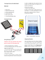
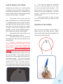
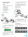
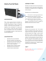
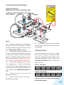
Horizon
Renewable Energy Education
Experiment Manual
CREDITS
Author:
John Gavlik
Contributors and Editors:
Horizon Education Team
Horizon Education and Design Team:
Dane Urry, Miro Zhang, Stone Shen
Copyright c 2010 by Horizon Fuel Cell Technologies.
All rights reserved. No part of this publication may be
reproduced or transmitted in any form or by any means,
electronic or mechanical, including photocopy, recording,
or any information storage and retrieval system, without
permission in writing from the publisher.
Horizon Fuel Cell Technologies
Block 19, No.2 Suide Rd.
Shanghai 200331, P.R. China
http://www.horizonfuelcell.com
Horizon
Renewable Energy Education
Experiment Manual
Contents
Experiment Guide Introduction
1-16
Solar Energy Experiments
18-38
Wind Energy Experiments
39-77
Energy from Hydrogen (Fuel Cell) Experiments
78-100
Ultra Cool Experiments
101-140
• Introduction
• Adding More Depth to the Experiments
• Supporting Information
• Grade Level and Subject Appropriateness
• Getting Familiar with the Kit
• Renewable Energy Monitor
• Electrical Components, Circuits, and Terminology
• Learning to Correctly Use a Multimeter
• Measuring Voltage, Current, Power and Resistance
• Ohm’s Law
• The WindPitch Educational Wind Turbine
• Adapting Other Horizon Products to the Experiments
1. The Effect of Heat on Solar Panels
2. The Effect of Shade on Solar Panels
3. The Effect of Tilt Angle on Solar Panels
4. Finding the Solar Panel’s Maximum Power Point
5. Wind Power - How Many Blades Are Best - 1, 2, 3 ... More?
6. Wind Power - Using Three Different Curved Blade Shapes
7. Wind Power - Using Blades You Make Yourself
8. Wind Power - Turbine Efficiencies
9. Wind Power - Measuring RPM
10. Wind Power -Tuning For Maximum Power
11. Wind Power- To Generate Hydrogen
12. Electrolysis Mode Generating Hydrogen and Oxygen from Water
13. Fuel Cell Mode Generating Electricity from Hydrogen and Oxygen
14. Determining the Minimum Voltage for Water Decomposition
15. Polarization States for Hydrogen Fuel Cells
16. Build a Solar Farm
17. Build a Wind Farm
18. Build a Fuel Cells Stack
19. Running Your School With Hydrogen
20. Running Your School With Solar Power
21. Running Your School With Wind Power
About the Author
141
Introduction
Renewable Energy
Science Education Set
The Horizon Renewable Energy Science
Education Set p r o v i d e s f o r i n t e r e s t i n g
experiments with fuel cells, solar panels and
wind turbines. In addition, other electrical
components such as resistors, LEDs motors
and propellers are used as “loads” for these
devices. If you are unsure about the term
“load” or what a resistor or LED really is and
does, refer to the “Electrical Components
and Circuits” section of this manual where
you will find a host of useful information on
basic electricity concepts and the components
used in the experiments.
The experiments are sub-divided into
functional sections that cover solar panels,
stationary fuel cells, a wind turbine and fuel
cell car experiments. You don’t have to
perform the experiments in any particular
order, so feel free to skip around from one to
the other as you and your students see fit.
In addition to the standard experiments there
are some Ultra Cool ones that provide even
more excitement and desire to learn on the
part of students. Learning math and science
using renewable energy will inspire your
students to greater goals and achievements.
Adding More Depth to the
Experiments
Each experiment follows a similar outline
that not only provides a mechanism for easy
performance and an understanding of what to
do, it also gives your students the opportunity
to expand on the experiment by posing
“What If” questions on the experiment just
performed. For example:
What if - you changed the tilt angle of the
solar panel? Will it make any difference in
the voltage, current and power outputs?
What if - a wind turbine had longer
blades? Will it generate more or less
power compared to a wind turbine with
shorter blades?
What if - a fuel cell used pure oxygen
instead of plain air? Will it generate more
power when it mixed with pure hydrogen?
These and other practical and hypothetical
questions are posed for each experiment.
There are also related research questions
that give students the opportunity to go
beyond the experimental procedures to
discover more about the renewable energy
technologies they are studying.
Supporting Information
The experiments are supported by additional
information found in the accompanying
publication “Renewable Energy Science
Education Manual” that provides an
exceptionally rich amount of data, photos and
illustrations on the following topics:
Chapter 1: The Environment and Climate Change
Chapter 2: Solar Energy
Chapter 3: Wind Energy
Chapter 4: Electrolyzers
Chapter 5: Fuel Cells
Chapter 6: Hydrogen Storage & Transportation
Chapter 7: Basic Power Electronics
1
Cross reference is made between the
The experiments can fit into physics,
two publications to give you and your
chemistry, earth science, life science, and
students more complete background on the
environmental studies – virtually any subject
experimental processes along with sources
that deals with energy and the environment.
for more research. Look for the highlighted
references contained in the two publications.
The basis for the experiments is on basic
electricity and how solar panels, wind turbines
and fuel cells generate and use it. Topics
such as Ohm’s Law, electrical power and
energy are a continuing theme throughout all
of them. If first year algebra is too advanced
for younger students there is our Renewable
Energy Monitor that measures everything
without any calculations and displays it on the
classroom computer in full-color graphics (see
page 4).
For more advanced studies of physics and
chemistry the “Renewable Energy Science
Education Manual” (at the left) contains
numerous examples of advanced theory
and math to support any level of technical
background necessary for these subjects.
Teachers can feel confident in knowing
that the experiments and the supporting
information comply with the following
approved standards:
National Science Education Standards
(NSES)
Grade Level and Subject
Appropriateness
The experiments are easy to follow and
are designed for all middle and high school
students, worldwide. Teachers will appreciate
the clear, unambiguous instructions for
each step of the experimental procedures
along with how students are able to quickly
comprehend the material.
2
National Science Teachers Association
(NSTA)
T h e I n t e r n a t i o n a l Te c h n o l o g y
Education Association (ITEA)
Details of compliance to these standards are
found under separate documents outside of
this manual.
Getting Familiar with the Kit
The Horizon Renewable Energy Science
Education Set contains four basic devices that
you will use for the experiments. These are:
•
A Solar Panel
•
A Wind Turbine
•
PEM Fuel Cell
•
PEM Electrolyzer
Experiment 9: Preparation of the Electrolyzer
Module and Wind Powered Hydrogen Production
Connect the red and black cables to the corresponding terminals located on
the wind turbine and reversible fuel cell. For best results using the WindPitch
to generate hydrogen using the included reversible fuel cell, setup the wind
turbine hub with six (6) profiled blades supplied with the kit. Use combinations
of the BP-28, NCAA 44 or NCAA 63 blades.
Set the blade pitch to 15 degrees. Make sure that the wind turbine is generating AT LEAST 1.5 volts. If not, move the wind turbine closer to the fan until it
does. Also, make sure that the blade pitch is between 10 and 15 degrees. The
wind turbine is sensitive to this setting at high wind speeds.
Allow the table fan and wind turbine to run for 10 minutes on high wind speed
setting to generate sufficient amounts of hydrogen and oxygen gases that are
stored in the water/gas tanks.
EXPERIMENT 9
Experiments are designed around these
three renewable energy devices. You will find
complete information on the assembly and
use of these devices in a separate document
entitled:
Battery
Pack
If the wind is sufficient the system will now start to produce hydrogen and oxygen in the respective cylinders. When bubbles begin to
surface in the hydrogen cylinder the cycle is complete. Disconnect the reversible fuel cell from the Wind Turbine.
Procedure for repeated gas production: Disconnect the small plugs from the tubes connected to the nozzles on the reversible fuel cell. This
will allow water into the inner cylinders to replace the gasses and reset water levels to “0” line. Re-insert the plugs into the tubes and repeat
electrolysis again.
Note: You may also use the battery pack to perform electrolysis (In the case of no wind source)
Please remove the screw from cover of battery box using a screw driver.
Push and slide the cover and open the battery box.
Try NOT to touch the cables when you open the cover.
Place two AA batteries as indicated.
Push and slide the battery box cover to closed position and screw fightly
into place using screw driver.
Renewable Energy Education Set
ASSEMBLY GUIDE
EXPERIMENT 10
Experiment 10(alternative): Using the Battery Pack to
Perform Electrolysis (in the case of no sun or wind)
Push and slide
open the cover
Remove the screw
from the cover
AA
ry
tte
Ba
AA
r
tte
Ba
y
Make sure the switch on the battery box is in the "off" position before you
place the batteries into the box.
WARNING: If the cable is short circuited the batteries inside could
become hot and potentially cause burns, melting of parts, or create
risk of fire.
Note: Battery’s energy may be consumed after 4-5 times of use.
6
YOU ARE STRONGLY ENCOURAGED to
read and understand this information before
Experiment 3: Preparation of the Electrolyzer Module and
Solar Powered Hydrogen Production
proceeding with the experiments. Here are
Insert the electrolyzer, terminals on top, into the slot on the base. Cut 2 x 4cm length pieces of
rubber tube and insert a black pin into the end of one tube. Place the tube with the black pin
into the top pin on the hydrogen side (with black terminal). Place the other tube firmly onto the
top input nozzle on the oxygen side.
samples of the information presented.
Renewable Energy Education Set
What do you need?
REES
ASSEMBLY MAP
AA batteries=2 Units
Water=25ml
Scissors
For more detailed description of experimentation possible with this kit refer to the manual provided on CD-ROM.
IMPORTANT: Use common sense when connecting the parts described in this guide. Improper connections can cause failure and
permanent damage to your equipment.
Experiment 1: Use a Solar Panel to Power the
LED Module
Connect the cables to the solar cell/panel and circuit board to power LED
module as shown. Make sure black and red cables are used with the red and
black terminals respectively.
Fill the syringe with DISTILED water. On the red oxygen side of the electrolyzer, connect the
syringe to the uncapped tube. Fill the electrolyzer until water begins to flow out of the tube.
Attach a red plug to the Oxygen side tube. Let settle for 3 min.
Attach the round cylinders to the cylinder base and insert the inner cylinders into the outer
ones. Make sure the plastic rims do not cover the openings located on the bottom of the inner
cylinders.
Cut out a 16cm length tube. Place it through the holes on the white clincher, with the clincher 4
cm from the end of the tube.
Connect the long end of the tube to the inner hydrogen cylinder. Connect the other end of the
tube to the bottom end of the black hydrogen side of the electrolyzer. Connect a 16cm length
of tube to the inner oxygen cylinder and then to the red oxygen side of the electrolyzer.
Pour 20ml water into each cylinder.
Disconnect the red pin from the tube on the electrolyzer. The water should fill the inner
container, then reconnect the red pin. Repeat on the Hydrogen side.
Connect the electrolyzer to the solar panel using the corresponding cables and expose to
direct sunlight. (Important: make sure connections are correct or permanent damage can
occur. Make sure the clincher is OPEN.)
The system will now start to produce oxygen and hydrogen in the respective cylinders. When
bubbles begin to surface in the cylinder the cycle is complete. Disconnect the electrolyzer.
EXPERIMENT 3
EXPERIMENT 1
Experiment 2: Use a Solar Panel to Power a
Small Fan and a Small Car Wheel Module
Assembly of the small electric fan:
Connect small round white adapter to the motor axis. Connect the fan blade
to the adapter.
Assembly of the car wheel:
Firmly connect the other (tapered) white adapter to the motor axis. Attach the
small wheel to the adapter.
Connect the solar panel to the circuit board then to the motor base as shown.
The fan may need to be flicked with your finger to start.
EXPERIMENT 2
3
Renewable Energy Monitor
(Optional- not included)
Use it with or
Without a Computer
Horizon has developed the Renewable
The Renewable Energy Monitor can be used
Energy Monitor to enhance your study of
with or without a computer – indoors or out –
renewable energy. The following is provided
and it works with all Horizon solar, wind and fuel
as a quick guide to its features and operation.
cell products.
For complete details refer to the Renewable
where they perform best – outdoors – and
Energy Monitor User Manual that comes with it.
measure all the data there.
Main Features
With the USB interface the Renewable Energy
Do solar and wind experiments
Monitor plugs directly into your computer. The
computer displays real-time plots of actual
measurements that give students a visual
understanding of what’s going on.
LCD Screen
The LCD screen displays all the data at once
without moving wire probes like on a multimeter.
And students can switch between screens with
The Renewable Energy Monitor provides
complete measurement and display functions
for all the experiments; plus, it can be used as
a general purpose meter instead of a multimeter for your electrical measurements. And
it does it automatically – no computations!!
Example Computer Plot of Voltage, Current, Power
and Resistance
4
just a push of a button. Horizon has made
the complicated simple – and powerful – so
that you and your students spend more time
experimenting and less time figuring out how to
hook things up.
Electrical Components,
Circuits and Terminology
The following information will help you to
understand some of the components, circuits
and terminology used in the experiments.
Each is presented in the form of a question.
What is Current?
Electrical current is to electricity as the
volume of water is to water flow. A fire hose
can carry more water at higher pressure
compared with a clogged shower head. So
too can lager wires carry more current as
compared with smaller wires.
What is Voltage?
Voltage is to electricity as pressure is to
water; both are forces that move things.
Voltage is the force that moves electrons
through a circuit; the greater the voltage
the greater the force of electron movement.
Voltage is generated by creating a “potential
difference” between positive and negative
elements of the device generating it.
Electrical current carries electrons along a
path (called a circuit) like water carries water
molecules through a hose. More electrons
mean more current flow.
Water normally flows from upstream to
downstream using gravity as a force.
Electrical current normally flows from positive
(+) to negative (-), which is called direct
current or DC for short, but gravity is not
involved.
Like water, the higher the voltage, the more
force it exerts. Water falling from a height uses
gravity to create force; the higher the water
falls (its potential difference), the more force
or pressure it creates. Unlike water, however,
voltage is not created by gravity but by
chemical, optical, or magnetic forces.
Batteries use chemicals to generate voltage
while common fuel cells use electrons in
hydrogen gas to create voltage. Solar panels
use optical means to capture the sun’s photons
to do the same and wind turbines use rotating
magnets that are very close to coils of wire that
generate voltage based on the magnetic fields
created by the magnet’s rotation.
Unlike water, electrical current can flow in
either direction – positive to negative and
negative to positive. The latter is usually
called alternating current, or AC, since the
current switches (alternates) between positive
and negative directions. Electrical current
produced by batteries are DC while electrical
current coming out of the wall socket is AC.
Both have their applications in electronic
circuits.
Current is measured in units called
amperes or amps
Voltage is measured in units called volts
5
What is a Resistance?
What is a Resistor?
A potentiometer is a variable resistor
much like the knob on your car radio. You
adjust it for various resistance values. The
potentiometer supplied with the kit can be
adjusted from 100 to 0 ohms. The two round
connectors allow you to plug it into any of the
experimental circuits with the supplied wires.
A resistor is a passive electrical device
usually composed of a material like carbon
that limits the flow of current from a power
source. Resistors are normally considered
as loads and are important components in
any electrical circuit.
The physical part and electrical symbol for a
resistor are shown below. This is a kind of
“fixed value” resistor because it has only one
resistance value.
Larger wires can carry more electrical current
as compared with smaller wires. In electrical
circuit boards, components called resistors
are inserted in the circuit to limit current flow.
The resistance to the flow of electrons
depends on the type and size of the materials
used. While water flowing in a pipe does not
generally produce heat by itself, electrical
resistive materials produce varying degrees of
heat created by the flow of electrons through
the material. Heat is generally considered
wasted energy (as in a hot light bulb) but not
always, as in a toaster or hair dryer where
heat from resistance is the desired quantity.
Resistance is measured in units called
ohms.
6
A resistor’s value is specified in ohms
What is a Potentiometer?
A potentiometer is a variable resistor much
like the knob on your car radio. You adjust
it for various resistance values. It has three
terminals – left, center and right. Horizon has
made it simple to use with a dial that shows
resistance from 100 to 0 ohms.
What is a Power Source?
What is a Load?
An electrical power source
A load is a device that absorbs the power
is a device that produces
coming from a power source and uses the
electrical voltage and current
power to do work, like spin a motor, or simply
and power. Power sources
dissipate the power into heat like the coils of
can use chemical energy like
wire in a toaster. In all cases, loads are used
a battery or fuel cell, solar
to both consume and regulate the power
energy like a solar panel or
being produced. Generally speaking, a load
wind energy coupled with
is measured as resistance in units called
magnetic energy such as a
ohms.
wind turbine. Each of these
Very Heavy Load
power sources converts one
kind of energy (chemical, light
or mechanical) to electrical
energy.
Heavy Load
Light Load
100
ohms
10
ohms
1
ohm
The equation for electrical power is shown below:
P = V * I where
P = Power in watts
V = Voltage in volts
I = Current in amps
In relative terms, a “light” load has a large
resistance and a “heavy” load has a small
resistance. This may be counter intuitive, but
it is the case, nevertheless. For example, a
100 ohm resistor presents a “lighter” load to
What is a Circuit?
A circuit is any “unbroken” or closed
connection of electrical components that form
a continuous conducting path for current to
flow; if the circuit is “broken” (or open as in
a circuit as compared with a 10 ohm resistor.
The illustration below shows the relative
electrical “weight” of three typical resistor
loads. The fuel cell and motor-propeller are
each about 2 to 4 ohms making them a very
heavy load.
an open circuit) no current can flow and no
power or energy can be delivered.
The most basic electrical circuit is made up
of a power source (like a battery shown here)
attached to a load (like a resistor shown
here).
7
What is a Series Circuit?
What is a Parallel Circuit?
In an electrical circuit several devices such
as light bulbs can be placed in a line - or in
series - between the positive and negative
poles of the battery. This is called a series
circuit.
Devices can be arranged in a parallel circuit
such that if any bulbs burn out the circuit still
remains intact and operates. Holiday lights
are wired in parallel so that if one bulb burns
out the others remain lit.
A major problem is if one light bulb burns
out, then it acts like a switch and turns off
the whole circuit. On the other hand a major
advantage of a series circuit is that it saves
wires that are needed in a parallel circuit.
The circuit below shows two lights wired in
parallel. If one light burns out the other one
stays on.
What is Power?
What is Energy?
Power is the combination of voltage and
current. Voltage is the pressure component
of power forcing electrons to move through a
circuit, and current is the quantity component
of power indicating the amount of electrons
in the flow. Both voltage and current are
required to produce the electrical force called
power. Power is instantaneous and is not
measured over time like energy. When you
measure power, you measure voltage and
current for a given instant of time.
This is an important distinction – time, or
lack of it, is the essential difference between
power and energy. Power is instantaneous
while energy is power measured over time.
Electrical power is measured in units
called watts.
8
Energy is power over time. Energy is the power
flowing through a circuit for a given time like
one second, one minute or one hour. When we
speak of energy we mean power times time.
Energy is measured in units similar to power
but with a time component as in watt-seconds
(or Joules), watt-minutes or watt-hours.
If a circuit generates 1 watt of power for 1 hour,
it is said to generate 1 Watt-Hour of energy.
Your electric meter measures power in WattHours (3600 Joules), but that can be converted
to any other time frame by understanding how
time is measured – one hour = 3600 seconds.
Energy is measured in Joules (wattseconds) in the experiments.
Learning to Correctly Use
A Multimeter
A multimeter combines measuring
voltage, current and resistance into a single
instrument. While somewhat intimidating for
first time users there are a few simple and
effective ways to make these measurements
for the experiments. This section shows you
how.
Manual
For safety reasons DO NOT
connect a multimeter to the 110
VAC wall socket or to electrical
appliances that are plugged in to it.
Auto
A Simple Circuit
Selecting the right multimeter
dial position is just the start.
To correctly measure voltage,
current and resistance the
Types of Digital Multimeters
There are basically two types of digital
multimeters – manual (left) and auto ranging
(right). As you can see the manual model
on the left has more dial positions, so you
have to be careful to select the right one
for your measurement. The auto ranging
type on the right, which is usually more
expensive, does most of the work for you.
All you need to do is select the desired
function like voltage, current or resistance
and it makes the measurement at the proper
scale. However, for both meters you need
to know how to correctly attach the leads for
multimeter leads must be
inserted into the circuit in the
correct manner.
As an example we will start
with a simple but typical circuit
to see how each of these
measurements is made. This
one is composed of a solar
panel as the voltage source and a resistor as
the load. Other circuits will include fuel cells,
motors and other components; however, the
technique for measurement is essentially
the same. Let’s start with the easiest
measurement and progress to the more
difficult ones.
the measurement.
9
Measuring Voltage
Measuring Current
To measure voltage:
To measure current the circuit must be
•
Set the dial to the proper DC (direct “interrupted” or “broken” and the multimeter
current) voltage range (V)
must be placed in series with the circuit.
•
Connect the red lead to the positive Notice that you may need extra clip leads to
(+) side of the part to be measured
attach the parts of the circuit together.
•
Connect the black COM lead to the •
Set the dial to the proper DC (direct negative (-) side to be measured
current) current range usually in A or •
Read the voltage on the display
ma or milliamps
•
Connect the red lead to the positive (+) side of the voltage source (the solar panel in this example)
•
Connect a clip lead from the negative (-) side of the voltage source to one side of the resistor
•
Connect the black COM lead to the other side of the resistor
•
Read the current on the display
See Ohm’s Law below for an
easier way to determine current
without disturbing the circuit
10
If you have two of the three quantities
Measuring Resistance
already measured you can compute the third.
In order to measure the resistance of
a component at least one side of
the
component must be free and away from the
circuit. For best results both sides should be
free of the circuit.
•
Set the dial to resistance - normally shown with the omega ( ) symbol.
•
Connect the red lead to one end of the resistor
•
Connect the black COM lead to the other end of the resistor
•
Read the resistance in ohms on the display
For example if you measured current and
resistance you can calculate voltage by the
following equation:
V=I*R
If you have voltage and current, you can
compute resistance:
R=V/I
And if you know the voltage and resistance
you can compute current:
I = V / R
(see below for computing current)
Use these simple and direct equations in the
experiment – especially the one for computing
current with voltage and resistance, since
it makes for a much easier measurement
sequence without having to interrupt or break
the circuit. If you know the resistance value
then computing current like that shown above
is a snap. If you don’t know the resistance
value (like using a motor for a load) you still
have to use the conventional way to measure
current.
Ohm’s Law
The multimeter measurements form the
basis for some basic electrical computations
referred to as Ohm’s Law after the German
physicist Georg Ohm, who, in 1827,
described measuring voltage and current
through simple electrical circuits containing
various lengths of wire. The mathematical
basis for Ohm’s Law can be stated as:
•
•
•
V = I * R
where
V = voltage in volts
I = current in amps
R = resistance in ohms
Computing Current Is As
Simple As 1, 2, 3
In order to quickly compute current using
Ohm’s Law with a known resistance and
voltage see the examples below:
Examples:
1.
Resistor = 100 ohms
2.
Voltage = 1 volt
3.
Current = 1 / 100 = 0.010 amps = 10
milliamps
1.
Resistor = 10 ohms
2.
Voltage = 1 volt
3.
Current = 1 / 10 = 0.100 amps = 100
milliamps
11
1.
Resistor = 50 ohms
2.
Voltage = 1 volt
3.
Current = 1 / 50 = 0.020 amps = 20
milliamps
1.
Resistor = 5 ohms
2.
Voltage = 1 volt
3.
Current = 1 / 5 = 0.200 amps = 200
M ea su rem en ts wi th
the Renewable Energy
Monitor - with no
calculations!
milliamps
Computing Power
You can compute power using voltage,
current and resistance. The equation for
power is:
P = V * I where •
P = power in watts
•
V = voltage in volts
•
I = current in amps
If you have the measurements for voltage and
current – or if you can compute current from
voltage and resistance – then use the above
equation to compute power. If you have the
measurements for voltage and resistance
but not current, you can use the following
equation by substituting the equation for
resistance:
P=V*I
P = V * (V / R)
P = (V * V) / R
P = V2 / R
Examples:
12
1.
Voltage = 1 volt
2.
Current = 20 milliamps
3.
Power = 1 x 20 = 20 milliwatts
1.
Voltage = 4 volts
2.
Resistance = 100 ohms
3.
Power = (4 * 4) / 100 = 16 / 100 = 0.016 watts = 16 milliwatts
Instead of using a multimeter with its
complicated dial and hookups Horizon
developed the Renewable Energy Monitor
to allow you to directly measure and display
voltage, current, power, resistance, energy
and RPM directly and without computations.
Simply attach the Renewable Energy Monitor
to a solar panel, fuel cell or wind turbine and
read the measurements on the large LCD
screen.
That’s it! There’s nothing more to do…except
attach it to your classroom computer for even
more exciting visual measurements. And its
battery powered so you can use it anywhere
– indoors or out.
The WindPitch Wind Turbine
Using the Right Fan
The WindPitch wind turbine is an important
To g e t t h e b e s t p e r f o r m a n c e f r o m t h e
component of the Renewable Energy
WindPitch you must use the right fan. Here
Education Set. With it you can add from two
is a photo of the best kind of fan to use. It’s
to six blades of different shapes as well as
at least 20 inches in diameter with at least 3
make your own. And the blades are made
speed settings.
to aircraft standards just like real airplane
propellers. You can even adjust the pitch or
angle of the blades to get the most power
from the wind. This is a powerful and
practical experimental tool that teaches a
great deal about how actual wind turbines
work. An entire section of this Experiment
Manual is dedicated to the WindPitch. There
are experiments for:
•
Measuring RPM
•
Wind Turbine Efficiencies
•
Tuning for Maximum Power
•
Adding from Two to Six Blades
•
Adjusting Blade Pitch
•
And more…
Don’t skimp on a small table fan – it won’t
work as well and your experiments will not
have the desired results. Use a big fan that
produces lots of wind.
13
Adapting Other Horizon Products to the
Experiments
Besides the Renewable Energy Science
Education Set Horizon makes several
other products that can benefit from the
experiments presented here. These include:
•
Solar Hydrogen Education Kit
•
Hydro-Wind Kit
•
Hydrocar Education Kit
•
Fuel Cell Car Science Kit
•
WindPitch Education Kit
Adapting For Electrolysis
Where it is necessary to measure the voltage
(V) and current (I), pull out the metal parts
of both banana plugs “part way” to expose
them to the multimeter leads (not necessary
if using the Software Adaptor). Make sure to
keep them partially plugged into the red and
black terminals on the reversible fuel cell. The
balance of the electrolysis cycle is essentially
the same as in the experiments.
These products use a reversible fuel cell
while the experiments are designed for
separate electrolyzers and non-reversible
fuel cells. They can be easily adapted to the
experiments by using the equivalent setups
shown below. The next pages provide lists
of existing experiments that can be done with
them.
14
Adapting For Fuel Cells
Since these products use a reversible fuel
cell rather than an electrolyzer (be careful
– they look alike), there is no reason to use
a separate fuel cell when the experiment
calls for one. Rather, the reversible fuel
cell will do the same task. Follow the same
general procedures for the hookup leads as
in doing electrolysis. You will be substituting
individual resistor for the motor-fan in some
of the experiments.
15
The Effect of Shade on
Solar Panels
LEARNING OUTCOMES
Students are shown that shade from trees,
clouds and man made objects can cause a
disproportionate decrease in power output
and can even cause physical damage to a
solar panel.
Students come to understand that:
1. Shade is like turning off an internal power
switch that shuts off most of the power to the
rest of the solar panel.
2. Solar panels can be damaged by shade
if they do not have the appropriate internal
protection.
3. Solar panels on space satellites must
always be repositioned as they travel in orbit
around the Earth.
STUDENT ACTIVITIES
LESSON OVERVIEW
This lesson demonstrates how a solar panel
looses much of its power when even a small
part of it is shaded.
Students study the effect of shade on a solar
panel by first placing it in direct light without
any shade. Then the entire solar panel is
shaded by placing a sheet of facial tissue
between the light source and the panel to
simulate overcast. The tissue is removed
LESSON OBJECTIVES
•
Students will use the Scientific Process to perform the experiment.
•
Students will collect and analyze data.
•
Students will observe the photovoltaic effect of sunlight and artificial light producing electricity.
•
Students will learn how both overcast and shade affect solar panels.
•
Students will use the Internet to research lesson related topics.
and then only a small portion of the solar
panel is shaded with an opaque object like
a regular piece of paper while the rest of
the panel is fully illuminated. For each trial
students measure the solar panel’s voltage,
current and power levels in order to perform
later analysis.
SAFETY
Normal caution must be exercised when
using an artificial light source like a table lamp
to illuminate a solar panel. Be sure NOT to
overheat the solar panel as it will become
HOT TO THE TOUCH and may MELT THE
PLASTIC.
22
The Experiment with a Multimeter
in order to shade the entire panel but have
Materials
were an overcast day.
enough low light shining on the panel as if it
6. Record the voltage.
7. Remove the facial tissue.
1 - Solar panel
8. Apply a regular piece of paper directly over
1 - Goose neck table lamp
one fourth ( ¼ ) of the solar panel to cover
1 - 100 ohm potentiometer
that portion completely. Refer to Figure 1.
2 – Red hookup lead
9. Record the voltage.
2 – Black hookup lead
1 – Circuit Board Module Base
Equipment Setup
Figure 1 – Paper Shading ¼ Solar Panel
Doing the Experiment
Caution: Do not overheat the solar
panel or touch it if it becomes hot!
1. Set the potentiometer to 10 ohms.
2. Set the multimeter dial to DC Volts with a
range of at least 5 VDC.
3. Set the table lamp above the solar panel
and turn on the light – or place the panel in
direct sunlight which is best.
Preparing the Data
Have the students enter the voltage readings
in the table below. Have them compute the
current and power based on the 10 ohm
resistor load. Refer to the Experiment
Guide section for details on how to do this.
Step
Full light
Overcast
Shading
Volts
Amps
Watts
4. Record the voltage.
5. Place a single sheet of facial tissue
between the light source and the solar panel
23
The Experiment with the Renewable
Energy Monitor
this to occur.
Materials
5.
1 - Solar panel
in direct sunlight which is best.
1 - Goose neck table lamp
6.
Record the voltage, current and power.
1 - 100 ohm potentiometer
7.
Place a single sheet of facial tissue
2 – Red hookup leads
between the light source and the solar panel
2 – Black hookup leads
in order to shade the entire panel but have
4.
Push the Select Button until the Volts
Amps Watts display appears.
Set the table lamp above the solar
panel and turn on the light – or place the panel
enough low light shining on the panel as if it
Equipment Setup
were an overcast day.
8.
Record the voltage, current and power.
9.
Remove the facial tissue.
10.
Apply a regular piece of paper directly
over one fourth ( ¼ ) of the solar panel to cover
that portion completely. Refer to Figure 2.
11.
Record the voltage, current and power.
Doing the Experiment
Caution: Do not overheat the solar
panel or touch it if it becomes hot!
1.
Set the Renewable Energy Monitor
switch to Battery or Computer depending on
your hookup.
2.
Push the Select Button until the Ohms
display appears.
Figure 2 – Paper Shading ¼ Solar Panel
Preparing the Data
Have the students enter the voltage, current
3.
Adjust the potentiometer for 10 ohms.
Light must be shining on the solar panels for
24
and power data into the table below:
Step
Volts
Amps
Watts
Full light
Overcast
Shading
Wind Power
How Many Blades Are
Best - 1, 2, 3... More ?
LEARNING OUTCOMES
Students witness how two, three, four and six
blades produce varying amounts of power for
the same wind speed.
Students come to understand that:
1.
Adding more blades may, or may not,
generate more power.
2.
Adding more blades creates more
“drag” caused by increased wind resistance.
Using the right number of blades for a given
3.
Reducing the number of blades may
wind condition is important in extracting
result in higher output power.
the maximum electrical power from a wind
4.
turbine. In this experiment students gain an
with more blades.
The wind turbine will run smoother
understanding of the choices between the
numbers of blades that are necessary to
produce the most power.
STUDENT ACTIVITIES
Students select from the three types of
curved blades supplied for the model wind
LESSON OBJECTIVES
turbine. They start with two blades attached
•
Students will use the Scientific turbine’s power output at the highest fan
Process to perform the experiment.
speed setting. They add additional blades
•
Students will collect and analyze data.
and repeat the experiment until the final
•
Students will learn to use a model number of blades equals six. They then
wind turbine that generates a analyze the results of the power generated
safe level of DC electricity.
to determine the optimum number of blades
•
Students will learn about how different that produce the maximum power output.
numbers of blades produce different Students are free to mix and match from the
power outputs from the wind turbine.
three different blade types supplied with the
•
Students will use the Internet to wind turbine.
research lesson related topics.
to the hub and measure and record the wind
SAFETY
Be sure NOT to touch the spinning blades as
potential injury may result. Also, be sure to
wear safety glasses at all times to protect eyes
from injury.
39
The Experiment with a Multimeter
Note: You may mix and match any of the
Materials
sure to arrange the blades on the hub so that
1 – WindPitch Wind Turbine
make sure that you keep the pitch angle the
1- Table fan (20” diameter recommended)
same for each test; the wind turbine is very
1 - 100 ohm potentiometer
sensitive to it.
blades that come with the wind turbine. Make
they are symmetrical and balanced.
Also
6 – Curved blades
2 – Red hookup lead
1. Adjust the potentiometer dial to 75
2 – Black hookup lead
ohms.
1 – Circuit Board Module Base
2. Set the multimeter dial to Volts with a
range of at least 10 volts.
Wind Turbine Blades
3. To begin, install two (2) blades of any type on
its highest speed setting.
the wind turbine hub and attach the hub to
4. Measure the voltage.
the alternator shaft. Refer to the WindPitch
5. Repeat step 4 with 3 blades
Assembly Guide for instructions on how to
6. Repeat step 4 with 4 blades
do this. You will add more blades later.
7. Repeat step 4 with 6 blades
Equipment Setup
Place the table fan in front of the wind
turbine about 2 feet away from it and set it to
Preparing the Data
Have the students enter the voltage readings
in the table below. Then have them compute
the current and power based on the 75 ohm
resistor load for each step. Refer to the
Experiment Guide section for details on
how to do this. Listed below is an example of
our experiment.
Our Data
Doing the Experiment
Caution: Be careful not to touch the
spinning blades and wear safety
glasses to prevent eye injury!
40
Blades
2
3
4
6
Your Data
Blades
2
3
4
6
Resistance=75 ohms
Volts
6.160
6.528
6.375
6.639
Amps
0.083
0.088
0.086
0.089
Watts
0.511
0.574
0.548
0.591
Resistance=75 ohms
Volts
Amps
Watts
The Experiment with the
Renewable Energy Monitor
they are symmetrical and balanced.
Also
Materials
sensitive to it.
1 – WindPitch Wind Turbine
1.
1 – Table fan (20” diameter recommended)
switch to Battery or Computer depending on
1 – 100 ohm potentiometer
your hookup.
6 – Curved blades
2.
2 – Red hookup lead
mA-mW display appears.
make sure that you keep the pitch angle the
same for each test; the wind turbine is very
Set the Renewable Energy Monitor
Push the Select Button until the mV-
2 – Black hookup lead
1 – Circuit Board Module Base
Wind Turbine Blades
To begin, install two (2) blades of any type on
3.
Place the table fan directly in front of
the wind turbine hub and attach the hub to
the wind turbine about 2 feet away from it and
the alternator shaft. Refer to the WindPitch
set it to its highest speed setting.
Assembly Guide for instructions on how to
4.
do this. You will add more blades later.
until the maximum power in mW is displayed.
Adjust the 100 ohm potentiometer
5.
Record the voltage, current and
power.
Equipment Setup
Computer
is Optional
6.
Repeat step 5 with 3 blades.
7.
Repeat step 5 with 4 blades.
8.
Repeat step 5 with 6 blades.
Preparing the Data
Listed below is an example of our experiment.
Our Data
Doing the Experiment
Caution: Be careful not to touch the
spinning blades and wear safety
glasses to prevent eye injury!
Note: You may mix and match any of the
blades that come with the wind turbine. Make
Blades
2
3
4
6
mV
6160
6528
6375
6639
mA
83
88
86
89
mW
511
574
548
591
mV
mA
mW
Your Data
Blades
2
3
4
6
sure to arrange the blades on the hub so that
41
Guide for Making Custom Blades
6.
Designing and cutting out custom blades
are more customized and attractive. The
including the wind vane from sheet plastic is
following are some examples of custom
a fun thing for students to do. However, they
blades, but use your imagination – the sky’s
must be made aware of the following practical
the limit – just make sure to follow the rules
issues to be successful – and safe!
outlined above.
to color or paint the blades so that they
7.
1.
The blades can be made from any
paper materials such as construction paper
For more fun allow the students
Give your blades a name so that
you can tell which ones you used for each
experiment.
or cardboard paper that is rigid enough to
withstand the wind and not bend too easily.
First draw out the basic shape on a sheet
Examples of Custom Blades
of paper. Then cut it out and use it as a
template over the actual cardboard paper or
Here are some examples of the kinds of
other material to make the actual blades.
blades that you can make yourself. Make
2.
sure to create both long and short blades with
Use scissors and a hole punch to cut
the blades to the shape you want.
3.
some narrow and some wide.
The blades must be cut so that they
are balanced or else the wind turbine will not
spin properly.
4.
Important - The blades must also be
made so that they don’t fly apart or break
when spinning. This creates a dangerous
safety hazard. Always have students wear
safety goggles when any of the blades are
spinning.
5.
Each blade must be able to fit into
the hub provided. This means that the
bottom end of each blade must conform to
the template below.
The rest of the blade
can be any shape as long as it meets the
requirements of steps 1 through 4 above.
Your wind turbine came with three flat blades
so use this end as a guide for making your own.
51
F uel Cell Mode - Generating
Electricity from Hydrogen
and Oxygen
LEARNING OUTCOMES
Students are shown that the hydrogen
and oxygen produced in the experiment
entitled “Electrolysis Mode – Generating
Hydrogen and Oxygen from Water” can now
be recombined to generate DC electricity to
drive a small electric motor.
Students come to understand that:
1.
A fuel cell is like a battery that
supplies voltage and current into a load as
long as a supply of hydrogen and oxygen are
available.
2.
Fuel cells can operate with other
substances besides hydrogen and oxygen
including alkaline and methanol.
LESSON OVERVIEW
3.
The choice of fuel cell electrolyte
This lesson demonstrates how a fuel
which it is intended.
material is dependent on the application for
cell generates electricity from combining
hydrogen and oxygen. The Fuel Cell Mode
as it is called is just the reverse of the
STUDENT ACTIVITIES
Electrolysis Mode where water is split into
Students produce a sufficient quantity of
hydrogen and oxygen. In the Fuel Cell mode
hydrogen and oxygen via an electrolyzer then
the hydrogen and oxygen are recombined to
allow the fuel cell to recombine these gasses
create electricity.
to generate electricity. An electric motor is
used to consume the electricity. Power from
the fuel cell is measured with the motor just
LESSON OBJECTIVES
free-spinning and with it connected to a
•
Students will use the Scientific analyzed to determine the loading effect of
Process to perform the experiment.
the propeller.
•
Students will collect and analyze data.
•
Students will learn to use a reversible PEM fuel cell in the fuel cell mode.
•
Students will learn the principles of Be sure to wear safety glasses at all times to
generating DC electricity with a fuel cell.
protect eyes from injury.
•
Students will learn to calculate energy.
•
Students will use the Internet to research lesson related topics.
propeller as a load. Data are taken and later
SAFETY
83
The Experiment with a Multimeter
Equipment Setup #2
Materials
1 – Battery Pack (3 volt battery with switch)
1 – Electrolyzer apparatus
1 – Fuel cell
1 – Motor and propeller
2 – Red hookup leads
2 – Black hookup leads
1 – Circuit Board Module Base
1 – Fuel Cell Base
1 – Electrolyzer Base
Equipment Setup #1
6.
With the motor shaft free spinning
record the voltage and current. You will
need to place the multimeter in both
parallel (voltage) and series (current) wiring
configurations for this step. Refer to the
Experiment Guide for help.
7.
Apply the propeller to the motor shaft
and record the voltage and current again.
Preparing the Data
Have the students enter the voltage and
Doing the Experiment
1.
Set the multimeter dial to DC Volts
with a range of at least 5 VDC.
2.
Fill both the hydrogen and oxygen
cylinders to the 0ml marks with distilled
water. Make sure that the inner containers
completely fill with water.
3.
Set the ON-OFF switch on the battery
pack to ON.
4.
Set the battery switch to OFF when
the water in the hydrogen cylinder reaches
the 10ml mark.
5.
Switch to Equipment Setup #2. Take
care to maintain the hydrogen and oxygen
supplies by following the directions in the
Experiment Guide.
84
current readings in the table below. Have
them compute the power based on the
recorded voltage and current. Refer to the
Experiment Guide section for details on
how to do this. As an example we entered our
data.
Our Data
No Prop
With Prop
Volts
0.757
0.630
Amps
0.165
0.339
Watts
0.125
0.214
Volts
Amps
Watts
Your Data
No Prop
With Prop
The Experiment with the
Renewable Energy Monitor
Materials
1 – Battery Pack (3 volt battery with switch)
1 – Electrolyzer apparatus
1 – Fuel cell
1 – Motor and propeller
2 – Red hookup leads
2 – Black hookup leads
1 – Circuit Board Module Base
1 – Fuel Cell Base
1 – Electrolyzer Base
5.
Set the battery switch to OFF when
the water in the hydrogen cylinder reaches
the 10ml mark.
6.
Switch to Equipment Setup #2. Take
care to maintain the hydrogen and oxygen
supplies by following the directions in the
Experiment Guide.
Equipment Setup #2
Equipment Setup #1
7.
With the motor shaft free spinning
record the voltage, current and power.
8.
Apply the propeller to the motor shaft
and record the voltage, current and power
again.
Doing the Experiment
1.
Set the Renewable Energy Monitor
switch to Battery or Computer depending on
your hookup.
2.
Push the Select Button until the mVmA-mW display appears
Preparing the Data
Have the students enter the voltage, current
and power into the table below.
Our Data
No Prop
With Prop
Volts
0.757
0.630
Amps
0.165
0.339
Watts
0.125
0.214
Volts
Amps
Watts
Your Data
3.
Fill both the hydrogen and oxygen
cylinders to the 0ml marks with distilled
water. Make sure that the inner containers
completely fill with water.
4.
Set the ON-OFF switch on the battery
pack to ON.
No Prop
With Prop
85
Build a Fuel Cell Stack
LEARNING OUTCOMES
Students are shown that the fuel cells can be
arranged in series and parallel configurations
to produce the desired levels of voltage and
current outputs.
Students come to understand that:
1.
Fuel cells in series generate more
voltage with the same amount of current.
2.
LESSON OVERVIEW
This lesson demonstrates methods to
arrange two PEM fuel cells in series and
Fuel cells in parallel generate more
current with the same amount of voltage.
3.
The energy used to drive a motor-
propeller load with fuel cells in parallel is
different than with fuel cells in series.
parallel configurations in order to study the
voltage, current and power generated. It is
designed to be a simulation of a commercial
fuel cell stack in model scale where students
learn the potential of fuel cells as substitute
for rechargeable batteries in both home and
industrial applications.
STUDENT ACTIVITIES
Students first electrolyze “two” 10 ml water
units into hydrogen and oxygen using” two
separate electrolyzer apparatus” and in doing
so they measure the voltage, current, power
and time in order to compute input energy.
LESSON OBJECTIVES
•
Students will use the Scientific Process to perform the experiment.
•
Students will collect and analyze data.
•
Students will learn how to wire fuel cells in series and parallel.
•
Students learn to compute energy.
•
Students will use the Internet to research lesson related topics.
They then wire two fuel cells in series and
connect a motor-propeller to the fuel cells to
see how long the motor-propeller can spin.
This is followed by electrolyzing water again
and wiring the same fuel cells in parallel and
repeating the measurements. Data are taken
at each step for later analysis.
SAFETY
Be sure to wear safety glasses at all times to
protect eyes from injury.
123
The Experiment with a Multimeter
cylinders to the 0ml marks with distilled
Materials
are completely filled with water.
2 – Fuel Cells
pack to ON.
2 – Battery Pack (3 volt battery with switch)
5.
1 – Motor and propeller
to begin timing how long it takes for the
1 – Clock, watch or stopwatch
hydrogen to fill to the 10ml level on the
2 – Electrolyzer unit with gas storage containers
hydrogen cylinder.
3 – Red hookup leads
6.
3 – Black hookup leads
this is happening. You will need to place
1 – Circuit Board Module Base
the multimeter in both parallel (voltage) and
2 – Fuel Cell Base
series (current) wiring configurations for this
4– Red hookup leads
step. Refer to the Experiment Guide for help.
4 – Black hookup leads
7.
water. Make sure that the inner containers
4.
Set the ON-OFF switch on the battery
Note the time on the clock or watch
Record the voltage and current as
Set the battery switch to OFF when
the hydrogen cylinder reaches the 10ml mark.
Equipment Setup #1 –
Electrolyzing Water
8.
Note the time it took to create this
level of hydrogen and enter it into the table
below. Convert this time into seconds.
9.
Repeat steps 1 through 8 for the other
electrolyzer apparatus.
Preparing the Data
Have the students enter the time, voltage
and current readings in the table below.
Have them compute the power based on the
recorded voltage and current. Refer to the
Experiment Guide section for details on
how to do this. As an example we entered our
data.
Doing the Experiment
Part 1:
1.
Setup the equipment as in Equipment
Setup #1.
2.
Set the multimeter dial to DC Volts
with a range of at least 5 VDC.
3.
124
Fill both the hydrogen and oxygen
Part 1 - Our Data
Seconds
Volts
EL 1
175
2.227
EL 2
194
2.202
Part 1 - Your Data
Seconds
Volts
EL 1
EL 2
Amps
0.594
0.551
Watts
1.348
1.113
Amps
Watts
The Experiment with a Multimeter
Equipment Setup #2 –
Measuring the Time and Energy Used
to Power a Motor-Propeller with Fuel
Cells in Series
Part 2:
10.
Setup the equipment as in Equipment
Setup #2. Be sure not to release any of the
15.
Subtract the start time in step 11 from
the stop time in step 14 and convert this time
stored hydrogen and oxygen to the air. Refer
into seconds.
to the Experiment Guide for details.
Preparing the Data
11.
Connect the red wire from the fuel cell
to the Circuit Board Module Base and note
Have the students enter the time, voltage
the time on the clock or watch. If the motor
and current readings in the table below.
doesn’t immediately start spinning, give the
Have them compute the power based on the
blade a push with your finger being careful
recorded voltage and current. Refer to the
not to allow the rotating blade to cause injury.
Experiment Guide section for details on
12.
how to do this.
Record the voltage and current as
this is happening. You will need to place
the multimeter in both parallel (voltage) and
series (current) wiring configurations for this
step. Refer to the Experiment Guide for
help.
13.
Allow the motor to run until the
Part 2 - Our Data
Seconds
Volts
Part 2
90
1.041
Amps
0.560
Watts
0.580
Parts 2 - Your Data
Seconds
Volts
Amps
Watts
hydrogen is used up.
14.
Note the time when the motor-
propeller stops turning.
Proceed to Part 3 of the experiment on
the following page.
125
About the Author
John Gavlik is the founder and president
of LearnOnLine, Inc., (www.learnonline.com) a
company dedicated to promoting the application
of online teaching and learning to the mediums
of the Internet and World Wide Web. Mr. Gavlik
is a degreed electronic engineer who, with
his technical training, early on recognized the
potential of these new mediums for effective
distance education. This is especially true in
the case of collaborative learning that involves
individuals and groups that are geographically
separated.
One such collaborative project is the
Renewable Energy Education Lab, or REEL
Power, which uses renewable energy devices
such as solar panels, wind turbines and fuel
cells to help teach math and science. Designed
by Mr. Gavlik, REEL Power provides students
and teachers with both classroom and Internetbased teaching aids that allow them to do
experiments in class and reach out to other schools, worldwide, to share their activities using
YouTube, Skype, Twitter, Google Earth and other Internet tools.
Mr. Gavlik’s other professional work experience includes over 35 years of digital hardware,
software and embedded firmware design for leading commercial and aerospace companies
including Bendix Electrodynamics, Burroughs, Litton Guidance & Control, Jet Propulsion
Laboratory, RCA Avionics, Sonatech, Hayes Microcomputer Products, National Semiconductor
Corporation and Aerovironment.
In 1989 John co-founded MapTech, Inc., which was the first maritime electronic mapping
company to put nautical charts on CDROMs and linked them to GPS to make navigation easier
and safer for mariners of all sizes of boats. Maptech still maintains its dominant position in the field
of electronic mapping.
Mr. Gavlik is a graduate of the California Polytechnic State University (Cal Poly) with a
BSEE degree in Electronic Engineering. For more information about John and LearnOnLine,
please visit http://www.learnonline.com.
141