1
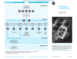
●
H1U Series PLC
User Manual
For applications where serious interference, high-frequency signal input or output cable selection shielded
cables should be to enhance the system of anti-interference capacity.
Please use the wire above 2mm2 to avoid connecting the grounding terminal at the same point as a heavy
electrical system.
STARTUP AND MAINTENANCE PRECAUTIONS
●
Danger
●
●
Do not touch any terminal while the PLC is power on. Doing so may cause electrical shock or malfunctions
Before cleaning or retightening terminals, externally cut off all phases of the power supply. Failure to do so
may expose you to shock hazard.
Please connect or remove the wire, the extension module and control unit wire after cutting off all power
supply, otherwise it may cause failures and malfunctions.
For online modify, coercible output, RUN, STOP and so on, you should read the instruction manual, and
operate the PLC after fully confirm its safety.
●
●
Table 3 Mounting Dimension
Mounting Dimension
Total I/Os
Model
A˄mm˅
B˄mm˅
Physical Dimension
H1U-0806M_
14
62
80
W×H×D˄mm˅
70×90×75
H1U-1410M_
24
83
80
93×90×75
H1U-1614M_
30
100
80
110×90×75
Product Structure
Ƶ Product Structure
! Note
●
●
Data: 19010084
V0.0
Thank you for purchasing the PLC of Inovance control technology co., Ltd.
Before using H2U series PLC, please read this manual carefully in order to use the products correctly.
This manual mainly describes specifications, features and usage of H2U series PLC, and there are PLC instructions
set summaries for easy reference. For both the user program development environment usage and programming
methods of this product, please refer to our company's “Auto-Shop programming software user's Guide "," H 2U
series PLC programming reference manual " and " H2U series communication manual”.
Features of H1U Series Programmable Controller:
Building-in large program memory space without an external extension memory card, it can up to 8K steps.
User program and all the power-down devices can be permanent backup in the power-off status, and the realtime clock can keep at least 20 days in power-down situations without batteries (power-on time is longer than 5
minutes).
Provide high-speedmulti-channel and high frequency I/O ports as well as excellent operation and positioning
control functions.
Integrate two independent communication ports, providing excellent communication protocols and MODBUS
instruction, which is convenient for system integration.
Comprehensive encryption features can protect users’ intellectual property rights.
With powerful networking and support CAN-BUS.
Safety Precautions
When handling extension card, be sure to cut off the power supply.
Please follow the industrial wastes disposal for the waste products.
Product Information
Ƶ Designation Rules
H1U-0806MRAX
1
ķ
ĸ
Ĺ
ĺ
Ļ
ļ Output type
Ľ Power Supply type
ľ Special function identification
Model
Danger
●
●
●
●
Turn off all the power supply externally before installation or wiring work in order to avoid electric shock or
damage of product.
Please connect AC power supply to the special terminal.
Make sure to attach the terminal cover offered as an accessory to the product before turning on the power or
starting the operation after installation or wiring work.
When processing for screw holes and wiring, do not make the metal filings and wires falling into the controller
ventilation hole, this may cause a fire, failure, and malfunction.
! Note
●
For of the main unit terminal or the extension unit terminaldo not use external power supply. Do not wire
vacant terminals externally.
Total I/Os
H1U-0806MR
H1U-0806MT
H1U-1410MR
H1U-1410MT
H1U-1614MR
H1U-1614MT
4
5
6
7
8
I/O Features
Total I/Ps
Hi-speed I/Ps
Input voltage
Total O/Ps
14
8
Two 60 kHz
Four 10 kHz
DC24V
6
24
14
Two 60 kHz
Four 10 kHz
DC24V
10
30
16
Two 60 kHz
Four 10 kHz
DC24V
14
Hi-speed O/Ps
Output Type
/
Relay
Three 100 kHz
Transistor
/
Relay
Three 100 kHz
Transistor
/
Relay
Three 100 kHz
Transistor
Ƶ General Specifications
Table 2 General Specifications
Environmental parameter
Type
Parameter
Unit
Low Temperature
ć
Storage ambient
Ambient condition
Transport ambient
condition Type
condition Parameter
Climatic- condition
Ambient temperature
Low temperature
Ambient
Temperature
High Temperature
ć
Humidity
Relative Humidity
%
Humidity
Relative humidity
Atmospheric
Pressure
Low Pressure
kPa
Atmospheric pressure
Low pressure
High Pressure
kPa
Sine Vibration
Mechanica-l Stress
! Note
●
Do not use the PLC in the place of dust, oil smoke, conducting dust, corrosive gas, and combustible gas,
exposure to the high temperature, dew, wind and rain, vibration and shock. Electric shock, fire, operator
errors can also cause the product damage and deterioration.
●
When processing for screw holes and wiring, do not make the metal filings and wires falling into the controller
ventilation hole, this may cause a fire, failure, and malfunction.
●
When the installation work of the new PLC is over, it needs to ensure that there is no foreign body on the face
of ventilation, including dust-proof and so on, otherwise, it may cause poor heat dissipation during running, a
fire, failure and malfunction.
●
Avoid charged state for wiring and plugging the cable plug, otherwise easily cause electric shock, or cause
damage to the circuit.
●
The Installation and wiring should be fixed and reliable, poor contact may cause incorrect operation.
●
If there is serious interference, the communications and high-frequency signal cable should be shielded
cables, to improve system anti-interference capacity.
WIRING PRECAUTIONS
3
Ƶ Basic Parameters
Climatic- Condition
Provide a safety circuit on the outside of the PLC so that the whole system operates to ensure the safety even
when external power supply trouble or PLC failure occurs. To be considered in the design includes:
●
On the outside of the PLC, an emergency stop circuit, a protection circuit, an interlock circuit, or a positioning
limit circuit may be necessary for preventing damage to the machine.
●
Ensure the safe operation of equipment, please design external protection circuit and safety mechanics for
the PLC output signals.
●
When the PLC CPU detects the system abnormal, all outputs may be turned off. During the controller circuit
failure, it may cause the output out of controlled. Design external circuits to ensure safe operations of the
machine in such a case.
●
When some sort of error occurs in a relay or transistor of the output unit, output may be kept on or off.
●
PLC design is applied to the indoor electric environment, its power system-level should have lightning
protection device, make sure that they will not lightning imposed on the PLC power input-side or signal input,
control output terminal, avoid damage the device.
INSTALLATION PRECAUTIONS
2
H: Inovance controller
1U: 1U series controller
08: 8 points input
06: 6 points input
M: Main module of general purpose controller;P: Positioning controller;
N: Network controller;E: Expansion module
R: Relay output type;T: Transistor output type
A: AC 220V Input omitted default:AC220V;B: AC110V input;
C: AC24V input;D: DC24V
Such as high speed I/O and analog function, etc.
Table 1 Basic Parameters
DESIGN PRECAUTIONS
Danger
Product Information
Series No.
Input points
Output points
Module classification
Random
vibration
Shock
Dipping
Displacement
mm
Acceleration
m/s2
High temperature
High pressure
Mechanica-l stress
Sine vibration
Fig2 Product Structure Diagram
Component names and Function descriptions:
1.
Big foldaway
2.
Power supply, auxiliary power supply and removable terminal for input signal
3.
LEDs for indicating the input status
4.
Download port for user program
5.
Mounting screw holes(two)
6.
RUN/STOP switch
7.
Buckle for two DIN rail mounting
8.
System program download port (Do not operate for non-professional)
9.
Special function expansion card interface
10. Special function expansion card fixed bolts(Screw specification: M2.6×6)
11. Wiring terminal for RS485 communication port
12. Special function expansion card(Available only after the user selection and installation)
Ƶ System Expansion
H1U series PLC supports only remote the expansion modules, do not support the local expansion modules. If
you need to connect the remote expansion modules to conduct the function expansion, you need to install CANBUS communication expansion cards, and then conduct networking connection via CAN-BUS communication
expansion cards and remote expansion modules. The model of CAN-BUS communications expansion card is
H1U-CAN-BD which should be purchased separately, as well as making sure that the main module of the software
version supports CAN-BUS functions. Otherwise the networking can not be performed. Please refer to the "H1UCAN-BD user manual," for the application of H1U-CAN-BD, refer to "H2U series expansion module user manual"
for the application of remote expansion modules, and refer to "H1/2U PLC instruction and programming manual."
for CAN-BUS functions.
System can be extended up to 64 points (support CAN-BUS devices), including the main module. As long as the
CAN-BUS protocol meets any device that can be hung on the bus.
Ƶ Hardware Interface
Terminal Block Definition
Terminal block definition of H1U-0806MR, H1U-0806MT
Displacement
S/S X1 X3 X5 X7
Acceleration
L
N X0 X2 X4 X6
Acceleration
Spectral Density
m /s (dB/Oct)
Frequency Range
Hz
Frequency range
0V Y0 Y1 Y2 Y4
Vibration Direction
/
Vibration direction
24V COM0COM 1 COM2 Y3 Y5
Type
Acceleration
Dipping
Height
2
3
Random vibration
/
Shock
Acceleration spectral density
Type
m/s2
Acceleration
m
Dipping
height
Dipping
Terminal block definition of H1U-1410MR, H1U-1410MT
S/S X1 X3 X5 X7 X11 X13 X15
L
Mechanical Design Reference
Ƶ Mounting Dimension
COM3
N X0 X2 X4 X6 X10 X12 X14
0V Y0 Y1 Y2 Y3 Y5 Y6 Y10
24V COM0COM 1COM 2COM3 Y4
COM4
Y7 Y11
ᅝ㺙ᄨ
Terminal block definition of H1U-1614MR, H1U-1614MT
S/S S/S X1 X3 X5 X7 X11 X13 X15 X17
L
N S/S X0 X2 X4 X6 X10 X12 X14 X16
0V Y0 Y1 Y2 Y4
24V C OM 0
C OM1
C OM2
C OM 3
Y7 Y11 Y12Y14
Y3 Y5 Y6 Y10 C OM4 Y13 Y15
Fig.1 Mounting Dimension Diagram
efesotomasyon.com
ķ ĸ
Ĺ ĺ
Ļ
ļ Ľ ľ
Terminal block specification: 22-14AWG wire.
When loosen the screw at two sides, loosen both sides of the terminal screws alternately, pay attention
not to completely one screw and then the other screw, just loosen the screw about half and then the other
screw, two screws alternately until the whole screw are loosened, then you can gently raise up terminal
head to finish the dismantling work of the terminal.
When mounting terminals, put the terminal head into position, and then tighten a screw to confirm the screw
will not fall off and then tighten the other screw, alternately tighten the screws on both sides until complete
the process. Note that during the entire fixed process, insert two sides of the terminal as balance as
possible, otherwise the terminals may damage by poor contact or short circuit.
Communication Interface Definition
The main PLC unit provides two communications ports.COM0 hardware has standard RS422 and RS485.
COM1 hardware is standard RS485.The terminal interface is Mini-DIN8 socket.
Table 4 COM0 Port Definition
Fig.3 COM0 Communication Port
485+
COM1
485-
Fig.4 COM1 Communication Port
Pin
No.
Signal
1
RXD-
Receive negative data
2
RXD+
Receive positive data
Description
3
GND
4
TXD-/RXD-
Grounding, no electrical connections for 9 and 10
5
+5V
External power supply +5V, the same with the internal logic +5V.
6
CCS
Communication direction control wire
7
TXD+/RXD+
8
NC
External transmit negative data. It can receive negative data if it is
RS485.
Item
Max. output
current
Relay outputs
Resistive load
2A/1 point :
8A/4 points common port,
8A/8 points common port
Inductive load
AC220Vˈ80VA
Lamp Load
AC220Vˈ100W
Transistor outputs
Max. output current
Programming Reference
Ƶ Soft component arrangement and power-off retentive
description
Table 8 Soft component arrangement
ON response delay
20 msec Max.
OFF response delay
20 msec Max.
High speed output: 10μs
Others: 0.5msec
High-speed output frequency
None
100kHz per channel(Max.)
Output common ports
Each group shared a common port, there is insulated gap between the groups.
Fuse protection
None
Internal equivalent circuit
PLC has a built-in power supply (DC24V) to detect user Xi input state, the user only needs to ON/OFF(dry-contact
switch) signal between Xi and COM, if a transistor output signal form the active sensor, it should be OC output
signal type.
PLC signal input and internal equivalent circuit is shown in the following figure, users’ circuit and PLC internal
circuit to connect via the terminal blocks. Figure 3-5 shows the SINK input method, “S/S” ” and “24V terminals are
short connection.
Input relay X
Output relay Y
Vac
100
220
240
Normal startup and operating range
Limit input voltage
Vac
85
/
264
Derating for usage When AC85 to100V and AC240 to 264V,see
Figure 3-2.
A
/
/
1
Input power
W/VA
/
/
15W/25VA
V
4.5
5
5.5
Output1
5V/GND
Output
voltage
Output
current
24VDD/GND
V
21.6
24
26.4
Output2
V
21.6
24
26.4
Output3
5V/GND
mA
50
500
500
24VDD/GND
mA
10
200
200
24VCC/COM
mA
10
200
200
Fig. 6 Source Input Connection
In some special applications, you may need to adopt SOURCE input methods, its equivalent input circuit shown in
Figure 6, "S/S" terminal and the "COM" terminals are short circuit.
Figure 7 shows the internal equivalent circuit diagram of the relay output module, the output terminal is divided
into several groups, each group is electrical isolation, and the contacts of different groups can connect with
different power circuits.
The sum of capacity load is the internal consumption and the
expansion module.
The maximum output power shall be the sum of each full load .
The cooling method is a natural cool.
Countants
Filter
function
DC24V
46 points 10ms
General
General
4.3k
Input :ON
Input current is more than 4.5mA.
Input current is less than 3.5 mA.
Input : OFF
Input current is less than 1.5mA
Input current is less than 1.5mA.
Digital Filter
X0 to X7 has digital filter function, the filter time can be set during the range of 0 to 60 msec.
Hardware Filter
The other I/O port is hardware filter except X0 to X7, the filter time is about 10 msec.
[T246~T249]
4 points 1ms
Accumulative,
retentive
32 bit count-up/down counter
[T250~T255]
6 points 100ms Actuarial,
retentive
High-speed counter
C0~C 15
[C16~C199]
C200~C219
16 points
168 points
20 points
15 points
21 points
General
Retentive
General
Retentive
Retentive
D0~D127
[D128~D7999]
128 points
7872 points
K
Retentive
[C220~C234]
[D1000~D7999]
[D8000~D8255]
Max.7000 points
It can be set to the
file register.
256 points
Special
P 0~P127
[C235~C255]
V7~V0ˈZ7~Z0
16 points
Index
I00*~I50*
8 points
128 points
6 points
Master Control
Jump subprogram
Input interrupt pointers
16 bit -32,768~32,767
16 bit
32 bit -2,147,483,648~2,147,483,647
0~FFFFH
32 bit
0~FFFFFFFFH
The soft components of H1U series PLC are permanent backup, which means that all soft components are not
loss after the module power-down. The real-time clock can hold for 15 days, which means that the clock is still the
current time after the module power-down and then restart within 15 days. The power-on time of the main module
must be more than 1 minute, otherwise the power-down may abnormal. The longer the power-on time is, the
longer the holding time will be, and the power-down time can hold up to 25 days.
Customer
information
Fig. 7 Relay Output Equivalent circuit
3.3k
High-speed Function
200 points 100ms
Add. of unit:
General inputs
Input resistance
Common connection terminal
T200~T245
H
Sink/Source mode.It is sink input when S/S terminal and 24V are shorted connection,it is source
when s/s terminal and COM are shorted connection.
Detection voltage
Electrical
parameters
Special
Product Warranty Card
Table 6 Input Specifications
Signal input mode
256 points
Latched
General
Ƶ Input Specifications
High-speed inputs X0̚X5
1152 points
General
Retentive
Output3 in table 5 is the sensor power supply, and it can also provide external power supply to the special function
module. Output2 provides power supply to the main module and the relay of IO expansion module. Output1
provides power to all modules. During the system configuration, make sure that power supply demand is not
exceed its maximum capacity.
Item
384 points
T0~T199
Nesting pointer
Fig. 5 Sink Input Connection
14 points
M8000~M8255
N0~N7
AC 85V input,full-loading output
24VCC/COM
10 points
[M384~M1535]
[S0-S999]
Data register Dˈ
VˈZ
Remark
Input current
Y000~Y015
16 bit count-up counter
Table 5 Power Supply Circuit Specification
Rated operating voltage
Y000~Y011
1000 points
Counter
Typical Max.
Value
Value
16 points
Y000~Y005
State
Timer
Non-pin
Min.
Value
H1U-1614M
X000~X017
14 points
[M0~M383]
Auxiliary Relay M
Ƶ Power Supply Circuit Specification
Unit
H1U-1410M
X000~X015
8 points
6 points
External send positive data. It can receive negative data if it is
RS485.
Item
H1U-0806M
X000~X007
Contact person:
P.C.:
Tel.:
Product model:
Fig. 8 Transistor Output Internal Equivalent circuit
The internal equivalent circuit diagram of the transistor-output-type PLC as shown in Figure 8. In which we can
see the output terminal is divided into several groups, and groups are electrical isolated each other. The transistor
output level can only be used for DC-DC24V load circuit.
For the inductive load in DC circuit, you should add a freewheeling diode, while the inductive load in AC circuit,
and add a RC component instead. As shown in Figure 9.
Name of unit:
Product
information
Body barcode (Attach here):
Name of agent:
X0 to X5 can realize the function with high-speed counting,interrupt and pluse capture,etc.
The maximum frequency of the X0 to X1 port counting up to 60kHz.
The maximum frequency of the X2 to X5 port counting up to 10kHz.
(Maintenance time and content):
Only a common terminal˖S/S
Failure
information
Note: S/S connecting to 24V+ or COM determines the SINK or SOURCE input mode, the selection is effective to
all the input points’ signals in main unit
Maintenance personnel:
Ƶ Output Specifications
Table 7 Output Specifications
Item
Relay outputs
Transistor outputs
Circuit Voltage
Less than AC250V and DC30V
DC5V to DC24V
Circuit Insulation
Relay Mechanical Insulation
Light coupling insulation
LED
When the relay output contacts close, the
LED light is on.
When the light coupling is drove,the LED light is on.
Leakage current during open
circuit
None
Less than 0.1mA/DC30V
Min.load
2mA/DC5V
5mA˄DC5V̚DC24V˅
Fig. 9 Diagram for Inductive Load Absorbing Circuit
Shenzhen Inovance Control Technology Co,.Ltd.
Address: Block E, Hongwei Industry Park, Liuxian Road, Baocheng No. 70 Zone, Bao’an District, Shenzhen
Fax: +86-755-29619897
P.C.: 518101
Service Hotline: 400-777-1260
Website: http://www.inovance.cn
efesotomasyon.com