1
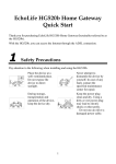
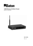
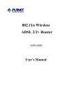
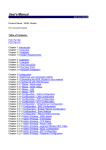
EchoLife HG520s Home Gateway
User Manual
HUAWEI TECHNOLOGIES CO., LTD.
EchoLife HG520s Home Gateway User Manual
Issue
01
Date
2008-02-15
No.
202064
Huawei Technologies Co., Ltd.
Address:
Huawei Industrial Base
Bantian, Longgang
Shenzhen 518129
People's Republic of China
Website:
http://www.huawei.com
Email:
terminal@huawei.com
Copyright © Huawei Technologies Co., Ltd. 2008. All rights reserved.
No part of this document may be reproduced or transmitted in any form or by
any means without prior written consent of Huawei Technologies Co., Ltd.
Trademarks and Permissions
and other Huawei trademarks are trademarks of Huawei Technologies
Co., Ltd.
All other trademarks and trade names mentioned in this document are the
property of their respective holders.
Notice
The information in this document is subject to change without notice. Every
effort has been made in the preparation of this document to ensure accuracy
of the contents, but all statements, information, and recommendations in this
document do not constitute the warranty of any kind, express or implied.
This product has been designed to comply with the requirements on
environmental protection. For the proper storage, use and disposal of this
product, national laws and regulations must be observed.
Safety Precautions
z
z
z
z
z
z
z
z
z
z
z
z
z
z
General Requirements:
Before you install and use the device, read these safety precautions
carefully and observe them during operation.
During storage, transportation and operation of the device, keep the
device dry.
During storage, transportation and operation of the device, avoid
collision and crash of the device.
Never attempt to dismantle the device by yourself. In case of any
fault, contact the appointed maintenance center for repair.
Without prior written consent, no organization or individual is
permitted to make any change to the structure or safety design of
the device. Huawei Technologies Co., Ltd. is not liable to any
consequences or legal issues due to such changes.
While using the device, observe all applicable laws, directives and
regulations, and respect the legal rights of other people.
Environmental Requirements:
Place the device at a well-ventilated place. Do not dispose the
device to direct sunlight.
Keep the device clean and free of dusts.
Place the device on a stable platform.
Do not place any object on top of the device. Otherwise, the device
may be too hot during operation. It can even be deformed or
damaged by the heavy load.
Keep at least 10 cm between the device and the closest object for
heat dissipation.
Do not place the device on or near any object that can easily catch
fire, such as something made of rubber.
Keep the device far away from any heat source or bare fire, such as
a candle or an electric heater.
Keep the device far away from any household appliance with strong
magnetic field or electromagnetic field, such as a microwave oven
or a refrigerator.
z
z
z
z
z
z
z
z
z
z
z
z
z
z
z
Operating Requirements:
Do no let a child operate the device without guidance.
Do not let a child play with the device or any accessory. Swallowing
the accessories may lead to peril.
Use the accessories provided or authorized by the manufacturer
only.
The power supply of the device shall meet the requirements of the
input voltage of the device.
Before plugging or unplugging any cable, shut down the device and
disconnect it from the power supply.
While plugging or unplugging any cable, make sure that your hands
are completely dry.
Do not tread on, pull or over-bend any cable. Otherwise, the cable
may be damaged, leading to malfunction of the device.
Do not use an old or a damaged power cable.
During lightning weather, stop using the device and disconnect it
from the power supply. Unplug the power plug and the ADSL twisted
pair, to avoid lightning strike.
If the device is not used for a long time, disconnect it from the power
supply and unplug the power plug.
In any of the following cases, stop using the device, disconnect it
from the power supply and unplug the power plug immediately:
there is smoke emitted from the device, or there is some abnormal
noise or smell. Contact the specified maintenance center for repair.
Avoid any object (such as metal shavings) from entering the device
from the heat dissipation intakes.
Do not scratch or abrade the shell of the device. This may lead to
malfunctions of the device. The shed painting material may also
lead to skin allergy.
Cleaning Requirements:
Before cleaning the device, stop using it and disconnect it from the
power supply.
Use a piece of soft cloth to clean the device.
z
Keep the power plug clean and dry. Using a dirty or wet power plug
may lead to electric shock or other perils.
Table of Contents
Chapter 1 Introduction ........................................................................1
1.1 Functions and Features.........................................................1
1.2 Hardware Configuration ........................................................1
1.2.1 Front Panel .................................................................2
1.2.2 Rear Panel..................................................................4
1.2.3 Splitter.........................................................................4
Chapter 2 Installation of the HG520s..................................................6
2.1 Preparation............................................................................6
2.2 Connecting the HG520s ........................................................6
2.3 Establishing Configuration Environment ...............................8
2.3.1 Parameter Configuration.............................................8
2.3.2 Steps...........................................................................9
2.4 Web Configuration Page .....................................................10
Chapter 3 Service Configuration.......................................................11
3.1 Method ................................................................................11
3.1.1 Protocol Model..........................................................11
3.1.2 Steps.........................................................................12
3.2 Service Modes of the HG520s ............................................12
3.3 Configuring the Bridge Mode ..............................................14
3.3.1 Preparation ...............................................................14
3.3.2 Steps.........................................................................15
3.4 Configuring the PPPoE Mode .............................................16
3.4.1 Preparation ...............................................................16
3.4.2 Steps.........................................................................17
i
3.5 Configuring the PPPoA mode .............................................18
3.6 Configuring the RFC2684B Mode .......................................18
3.6.1 Preparation ...............................................................18
3.6.2 Steps.........................................................................19
3.7 Configuring the RFC2684 (IPoA) Mode ..............................20
3.8 Configuring the Wireless Mode ...........................................20
3.8.1 Preparation ...............................................................20
3.8.2 Steps.........................................................................21
Chapter 4 Advanced Configuration...................................................24
4.1 Preparation..........................................................................24
4.2 Configuring the RIP .............................................................24
4.3 Configuring the Security ......................................................25
4.4 Configuring the Filter ...........................................................25
4.5 Configuring the QoS............................................................28
4.6 Configuring the Port Mapping .............................................31
4.7 Configuring the Timezone ...................................................32
4.8 Configuring the ACL ............................................................33
4.9 Configuring the TR069 ........................................................34
4.10 Configuring the UPnP........................................................36
Chapter 5 Other Settings ..................................................................37
5.1 Changing the IP Address of the LAN of the HG520s..........37
5.2 Changing the Administrator Password of the HG520s .......38
5.3 Restoring the Default Factory Settings ...............................38
5.4 Upgrading the Firmware......................................................39
ii
Chapter 6 Troubleshooting ...............................................................40
6.1 Quick Failure Location.........................................................40
6.2 FAQs ...................................................................................41
Chapter 7 Technical Specifications ..................................................43
Chapter 8 Appendix ..........................................................................44
8.1 Default Factory Settings ......................................................44
8.1.1 Common Default Parameters ...................................44
8.1.2 Default PVC Parameters ..........................................44
8.2 Abbreviations.......................................................................45
iii
Chapter 1 Introduction
This chapter introduces functions and structure of the EchoLife
HG520s Home Gateway (hereinafter referred to as the HG520s).
1.1 Functions and Features
The HG520s is a type of Asymmetric Digital Subscriber Line
(ADSL) terminal. Data, video and audio are transmitted through the
common telephone line at a higher rate by the HG520s.
The features of the HG520s are:
z
High transmission rate: The maximum downstream rate is
24 Mbit/s; the maximum upstream rate is
1.2 Mbit/s.
z
Strong network adaptability: The HG520s can be
interconnected with multiple Digital Subscriber Line Access
Multiplexer (DSLAMs).
z
Strong maintainability: The HG520s provides multiple
indicator status, which is convenient to locate failures.
z
Easy operation: The HG520s has a simple operation for the
configuration page.
1.2 Hardware Configuration
This section introduces the appearance and the structure of the
HG520s.
1
Note:
Figures of the front panel and the rear panel are only for your
reference.
1.2.1 Front Panel
Figure 1-1 shows the front panel of the HG520s.
WLAN
LAN4
LAN3
LAN2
LAN1 INTERNET ADSL POWER
Figure 1-1 Front panel of the HG520s
Table 1-1 shows indicators in the front panel.
Table 1-1 Indicators in the front panel
Indicator
Color
Status
Description
The connection is established in the
WLAN interface.
There are data being transmitted in
the WLAN interface.
No connection is established in the
WLAN interface.
On
WLAN
Green
Blinking
Off
2
Indicator
Color
Status
Description
The connection is established in the
LAN interface.
There are data being transmitted in
the LAN interface.
No connection is established in the
LAN interface.
The embedded PPPoE and PPPoA
dial-ups of the HG520s are
successful, but there is no data
transmission.
On
LAN1–4
Green
Blinking
Off
On
INTERNET
ADSL
POWER
Green
Blinking
There are data are being transmitted
in the INTERNET interface.
Off
The HG520s is in the bridge mode or
the PPPoE/PPPoA connection is not
established.
On
The DSL connection is established.
Blinking
There are data being transmitted in
the DSL connection or the DSL
connection is being activated.
Off
The telephone line is not connected
or the DSL connection is not
established.
On
The HG520s is powered on.
Off
The HG520s is powered off.
Green
Green
Note:
PPPoE = Point-to-Point over Ethernet
PPPoA = Point-to-Point over ATM
LAN = Local Area Network
WLAN = Wireless Local Area Network
Note:
If the HG520s fails to activate, it tries again after an interval. The ADSL
LINK indicator is off during the interval, lasting for about 1 minute.
3
1.2.2 Rear Panel
Figure 1-2 shows the rear panel of the HG520s.
RESET
POWER
ON/ OFF
LAN1
LAN2
LAN3
LAN4
ADSL
Figure 1-2 Rear panel of the HG520s
Table 1-2 shows interfaces and buttons in the rear panel.
Table 1-2 Interfaces and Buttons in the rear panel
Interface/Button
Description
Antenna
Antenna for wireless Internet access.
RESET
To restart the HG520s, press the RESET button and
release it within three seconds. To restore the default
settings of the HG520s, press the RESET button and
release it after three seconds. Once you use this
function, all your custom settings will be lost. Therefore,
please be careful when using it.
POWER
Connect to the power adapter.
ON/OFF
Power on/off the HG520s.
LAN 1–4
Ethernet interfaces.
To connect LAN network devices (such as a computer
and a switch).
ADSL
ADSL interface.
To connect the telephone jack or a splitter through a
telephone line.
1.2.3 Splitter
The external splitter can efficiently reduce the signal disturbance
on the telephone line. When voice and data are transmitted through the
4
same telephone line at the same time, you need an external splitter to
separate the voice and data signals:
z
LINE: Connecting to the phone jack on the wall.
z
PHONE: Connecting to the telephone.
z
MODEM: Connecting to the ADSL interface of the HG520s.
5
Chapter 2 Installation of the HG520s
This chapter introduces the installation when the HG520s is used
for the first time.
2.1 Preparation
Connect your computer with the HG520s through the Ethernet
interfaces. Before installing the HG520s, make sure that your computer
is equipped with the network card
2.2 Connecting the HG520s
Figure 2-1 shows the connection of the HG520s.
6
USB
(1) Power adaptor
(2) Switch
(3) Computer
(4) Set-Top Box
(5) Modem port of splitter
(6) Line interface
of splitter
(7) Phone interface of
splitter
(8) Splitter
(9) Phone
(10) Phone Jack
Figure 2-1 Connection of the HG520s
Connect the HG520s as follows:
Caution:
Before connecting the HG520s, power off the HG520s and your
computer.
(1)
Connect the interfaces of the splitter with the corresponding
equipment by using the telephone line.
7
z
Connect the LINE interface of the splitter with the telephone
jack on the wall.
z
Connect the MODEM interface of the splitter with the ADSL
interface of the HG520s.
z
Connect the PHONE interface of the splitter with the
interface of the telephone line.
(2)
(3)
(4)
Connect the Ethernet interface of the HG520s with the
Ethernet interface of the computer by using Ethernet cable.
Plug the output end of the provided power adapter into the
power input interface of the HG520s; plug the other end into
the power socket.
Press the POWER button of the HG520s in the rear panel to
power on the HG520s.
Check the power indicator in the front panel of the HG520s.
If it is on, the HG520s is power on.
2.3 Establishing Configuration Environment
You can configure the HG520s on the Web configuration page.
This section describes the process to establish the configuration
environment of the HG520s.
2.3.1 Parameter Configuration
Before establishing the configuration environment, set the
following parameters.
Table 2-1 Parameters for the configuration environment
Name
Administrator username and
password of the HG520s
Description
Default:
z Username: admin
z Password: admin
8
IP address and subnet mask
of the LAN of the HG520s
Default:
z IP address: 192.168.1.1
z Subnet mask: 255.255.255.0
IP address and subnet mask
of the computer
Set them to be in the same network
segment as the IP address of the LAN of the
HG520s
For example:
z IP address: 192.168.1.100
z Subnet mask: 255.255.255.0
2.3.2 Steps
Follow the steps to establish the configuration environment.
Step
1
2
3
To...
Do...
Connect the
HG520s
For details to connect the HG520s, refer to 2.2
"Connecting the HG520s."
Make sure not
to use the proxy
server.
The process to unselect this function is described
as follows (taking Internet Explorer 6.0 as an
example):
(1) Start the Internet Explorer. Select Tools >
Internet Options... to display the Internet
Options dialog box.
(2) Select the Connections tab. Click LAN
Settings....
(3) Deselect Use a proxy server for your LAN
(These settings will not apply to dial-up
or VPN connections).
Log in to the
Web
configuration
page
(1) In the address bar of Internet Explorer, enter
http://192.168.1.1 (the default IP address of
the HG520s). Then press Enter. The login
window is displayed.
(2) Enter the username and the password of the
administrator in the login window.
When the password is authenticated, you
can access the Web configuration page.
9
Note:
After configuring the parameters of the HG520s, configure the
computer according to the configuration status of the HG520s. For
details, please refer to Chapter 3 "Service Configuration."
2.4 Web Configuration Page
The Web configuration page of the HG520s is divided into two
parts:
z
The navigation tree: It is on the left side of the page. It
provides you to access to different configuration pages.
z
Configuration area: It is on the right side of the page.
10
Chapter 3 Service Configuration
This chapter introduces the method for configuring the HG520s.
Note:
The figures in the following configuration operations are only for your
reference.
3.1 Method
3.1.1 Protocol Model
Figure 3-1 shows the protocol model of for the connection
between the HG520s and the DSLAM at the office end.
PVC
MAC
ATM
ATM
MAC
PHY
PHY ADSL
ADSL
PHY
(1)
(2)
(1) Computer
(3)
(2) HG520s
(3) DSLAM
Figure 3-1 Protocol model
The transmission between the HG520s and the DSLAM is based
on the asynchronous transfer mode (ATM). In the service configuration
11
of the HG520s, you need to configure parameters, for example, the
permanent virtual channel (PVC).
3.1.2 Steps
The service modes of HG520s can be realized by configuring the
corresponding working parameters.
The steps to realize a service mode are described as follows.
Step
To...
Do...
Establish the
configuration
environment
Refer to "2.3 Establishing Configuration
Environment."
2
Configure the
HG520s
(1) Select the PVC to be configured.
(2) Select the service mode of this PVC and
configure the parameters of the PVC.
(3) Configure functions according to the
requirements.
For example, configure the DHCP function.
(4) Save the configuration and reboot the
HG520s.
3
Configure your
computer
Configure the parameters of the network card for
the computer or install the dial-up software in the
computer according to the service mode of the
HG520s.
1
Note:
DHCP = Dynamic Host Configuration Protocol
3.2 Service Modes of the HG520s
The HG520s supports multiple service modes and the
configuration of the DSLAM at the office end should be considered
when you select a service mode. Table 3-1 lists the service modes of
the HG520s.
12
Table 3-1 Service modes of the HG520s
Service Mode
Working Method
z
Bridge
z
z
z
PPPoE
z
z
z
PPPoA
z
z
z
RFC2684B
z
z
z
RFC2684 (IPoA)
z
Configuration
Take the HG520s as bridge
equipment.
Use the PPPoE dial-up software
of the computer for dialing.
Refer to 3.3
"Configuring
the Bridge
Mode."
Take the HG520s as a router.
Use the embedded PPPoE
dial-up software of the HG520s
for dialing.
Use the PPPoE encapsulation
mode to encapsulate the
packets.
Refer to 3.4
"Configuring
the PPPoE
Mode."
Take the HG520s as a router.
Use the PPPoA dial-up software
of the HG520s for dialing.
Use the PPPoA encapsulation
mode to encapsulate the
packets.
Refer to 3.5
"Configuring
the PPPoA
mode."
Take the HG520s as a router.
Use the static IP address or the
IP address dynamically allocated
by the ISP.
Use
the
IPoE/IPoA
encapsulation
mode
to
encapsulate the packets.
Refer to 3.6
"Configuring
the RFC2684B
Mode."
Take the HG520s as a router.
The HG520s uses the static
public IP address to access the
Internet.
Use the IPoA encapsulation
mode to encapsulate the
packets.
Refer to 3.7
"Configuring
the RFC2684
(IPoA) Mode."
Note:
ISP = Internet Service Provider
IPoA = Internet Protocol over ATM
13
Caution:
Some parameters are validated only after they are saved and the
HG520s is rebooted. Follow the prompt in the configuration page to
perform this operation.
3.3 Configuring the Bridge Mode
In the bridge mode, the HG520s serves as a bridge. You need to
install the Point to Point Protocol (PPP) dial-up software to realize the
dial-up access to the Internet.
This section describes the process to configure the HG520s to
work in the bridge mode and the process to configure your computer to
access the Internet through the HG520s.
3.3.1 Preparation
Table 3-2 shows the configuration for the bridge mode.
Table 3-2 Configuration for the bridge mode
Name
Configuration
PVC mode
Bridge
Encapsulation
RFC2684
VPI/VCI
Provided by the ISP
Multiplex
Provided by the ISP
PPP dial-up software
Install the PPP dial-up software on your
computer to access the Internet (The
Windows XP operating system is provided
with the PPP dial-up software)
Username and password for
the PPPoE dial-up
Provided by the ISP
14
Name
Configuration
Note:
VPI = Virtual Path Identifier
VCI = Virtual Channel Identifier
3.3.2 Steps
Configure the following equipment:
z
The HG520s
z
Your computer
1. Configuring the HG520s
Follow the steps:
(1)
(2)
(3)
(4)
(5)
Log in to the Web configuration page of the HG520s. For the
procedure, refer to "2.3 Establishing Configuration
Environment."
Select Basic > WAN Setting in the navigation tree to
display the WAN configuration page.
In the WAN configuration page, select the PVC that needs to
be configured.
Set Mode to Bridge. Configure relevant parameters
according to the values in the Table 3-2.
Click Submit.
2. Configuring your computer
After completing the configuration of the HG520s, you need to
install the PPP dial-up software to access the Internet.
The Windows XP (Professional) operating system has a
embedded PPPoE dial-up software. To set up a dial-up connection in
Windows XP system, do as follows:
15
(1)
Select Start > All Programs > Accessories >
Communications > Network Connections.
(2) Click Create a new connection in the displayed page.
(3) Click Next in the New Connection Wizard dialog box.
(4) Select Connect to the Internet and click Next.
(5) Select Set up my connection manually and click Next.
(6) Select Connect using a broadband connection that
requires a username and password and click Next.
(7) Enter the name of the connection. You can name it as you
like. Then click Next.
(8) Select an option from Anyone's use or My use only and
click Next.
(9) Enter the username and password. Then click Next.
(10) Click Finish.
3.4 Configuring the PPPoE Mode
In the PPPoE mode, the HG520s uses the embedded PPP dial-up
software for dialing. The HG520s serves as a router to connect your
computer to the Internet.
This section describes the process to configure the HG520s to
work in the PPPoE mode and the process to configure your computer
to access the Internet through the HG520s.
3.4.1 Preparation
Table 3-3 shows the configuration for the PPPoE mode.
Table 3-3 Configuration for the PPPoE mode
Name
Configuration
PVC mode
Routing
Encapsulation
PPPoE
Default route
Enable
VPI/VCI
Provided by the ISP
16
Name
Configuration
Multiplex
Provided by the ISP
Username and password for the
PPPoE dial-up
Provided by the ISP
DHCP mode of the HG520s
Enable the DHCP server
Note:
After the DHCP server is enabled, the HG520s allocates the private IP
address for the computer.
3.4.2 Steps
1. Configuring the HG520s
Follow the steps described as follows:
(1)
Log in to the Web configuration page. For the procedure,
refer to 2.2 (4)"2.3 ."
(2) Select Basic > WAN Setting in the navigation tree to
display the WAN configuration page.
(3) In the WAN configuration page, select the PVC that needs to
be configured.
(4) Set Mode to Routing.
(5) Set Encapsulation to PPPoE. Configure the relevant
parameters according to the values in the Table 3-3.
(6) Fill in the username and the password (provided by the ISP).
(7) Click Submit.
(8) Select Basic > DHCP in the navigation tree to display the
DHCP configuration page.
(9) Set DHCP to Server in the DHCP configuration page.
(10) Click Submit.
17
2. Configuring Your Computer
Configure the network card for your computer, to enable the
computer to automatically obtain information such as the IP address
and the gateway.
3.5 Configuring the PPPoA mode
In the PPPoA mode, the HG520s uses the embedded PPP dial-up
software for dialing.
Configuring the PPPoA mode is similar to configuring the PPPoE
mode. The only difference is that you have to select PPPoA in the PVC
configuration mode to configure PPPoA and select PPPoE to configure
PPPoE. For details, refer to 3.4 "Configuring the PPPoE Mode."
3.6 Configuring the RFC2684B Mode
This section describes the process to configure the HG520s in the
RFC2684B mode and the process to configure your computer to
access the Internet through the HG520s.
3.6.1 Preparation
Table 3-4 shows the configuration for the RFC2684b mode.
Table 3-4 Configuration for the RFC2684B mode
Name
Configuration
PVC mode
Routing
Encapsulation
RFC2684B
Default route
Enable
WAN IP address/subnet mask
There are two methods:
z Obtain IP address automatically
z Use the static IP address
VPI/VCI
Provided by the ISP
Multiplex
Provided by the ISP
18
Name
DHCP mode of the HG520s
Configuration
Enable the DHCP server
3.6.2 Steps
1. Configuring the HG520s
Follow the steps described as follows:
(1)
(2)
(3)
(4)
(5)
(6)
(7)
(8)
(9)
Log in to the Web configuration page. For the procedure,
refer to 2.2 (4)"2.3 Establishing Configuration
Environment."
Select Basic > WAN Setting in the navigation tree to
display the WAN configuration page.
In the WAN configuration page, select the PVC that needs to
be configured.
Set Mode to Routing.
Set Encapsulation to RFC2684B. Configure the relevant
parameters according to the values in the Table 3-4.
Click Submit.
Select Basic > DHCP in the navigation tree to display the
DHCP configuration page.
Set DHCP to Server in the DHCP configuration page.
Click Submit.
2. Configuring Your Computer
Configure the network card for your computer, to enable the
computer to automatically obtain information such as the IP address
and the gateway.
19
3.7 Configuring the RFC2684 (IPoA) Mode
Configuring the RFC2684 (IPoA) mode is similar to configuring the
RFC2684 (IPoA) mode. The only difference is that you have to select
RFC2684 (IPoA) in the PVC configuration mode to configure IPoA. For
details, refer to 3.6 "Configuring the RFC2684B Mode."
3.8 Configuring the Wireless Mode
In the Wireless mode, the HG520s makes you access the Internet
without connecting a cable.
This section describes the process to configure the HG520s to
work in the Wireless mode and the process to configure your computer
to access the Internet through the HG520s.
3.8.1 Preparation
Table 3-5 shows the configuration for the Wireless mode.
Table 3-5 Configuration for the Wireless mode
Name
Configuration
Access point
Enable
Channel ID
Select your country and district
Authentication type
There are three types:
z OpenSystem
z WEP-64Bits/WEP-128Bits
z WPA-PSK/WPA2-PSK
802.11b/g
There are three types:
z 802.11b
z 802.11g
z 802.11b/g
20
Name
Configuration
There are two types (found in the
authentication type of
WPA-PSK/WPA2-PSK):
z TKIP
z AES
Encryption
3.8.2 Steps
Follow the steps described below:
(1)
(2)
(3)
(4)
Log in to the Web configuration page. For the procedure,
refer to "2.3 Establishing Configuration Environment."
Select Basic > Wireless LAN in the navigation tree to
display the Wireless configuration page.
In the Wireless configuration page, enable the Access Point
and configure the relevant parameters according to the
values in Table 3-5.
Select one of the Authentication Type. Configuring the
mode of OpenSystem in Figure 3-2, the mode of
WEP-64Bits/WEP-128Bits in Figure 3-3, the mode of
WPA-PSK/WPA2-PSK in Figure 3-4.
Figure 3-2 Configuring the mode of OpenSystem
21
Figure 3-3 Configuring the mode of WEP-64Bits/WEP-128Bits
Figure 3-4 Configuring the mode of WPA-PSK/WPA2-PSK
(5)
Configure the wireless MAC
Figure 3-5. Then Click Submit.
22
address
filter
in
the
Figure 3-5 Configuring the wireless MAC address filter
23
Chapter 4 Advanced Configuration
This chapter introduces the method for deploying the advanced
configuration of HG520s.
4.1 Preparation
Follow the steps described below:
(1)
(2)
Log in to the Web configuration page of HG520s. For the
procedure, refer to "2.3 Establishing Configuration
Environment."
Select Advanced Configuration in the navigation tree to
display the advanced configuration page.
4.2 Configuring the RIP
You can enable the routing list to be automatically updated
through configuring the RIP.
Figure 4-1 Configuring the RIP
Name
Description
RIP Direction
Select the direction of communication of RIP:
None/Both/In only/Out only
RIP Version
Select a RIP version
24
4.3 Configuring the Security
Various types of data can be blocked to your computer, or the
firewall can be enabled to promote the level of security of network.
Figure 4-2 Configuring the Security
Name
Description
Internet Security
HG520s provides totally 6 types of data to block:
Telnet, FTP, TFTP, Web, SNMP and Ping
Firewall
The Firewall is enabled by default;
When SPI is enabled, all data form WAN will be
blocked
4.4 Configuring the Filter
Through configuring the Filter, you can filter prescribed IP address,
mask and ports, etc.
Name
Description
Filter Set Editing
25
Name
Filter Set Index
Description
1~10
Interface
Select PVC0~PVC7/LAN; Default is “NONE”
Direction
Select Both/Incoming/Outgoing
Filter Rule Editing
Filter Rule Index
1~6
Filter Type
Select TCP/IP, or MAC
Active
To activate a rule; Default is “No”
Source IP Address
Fill in the filtered source IP address you want
Subnet Mask
Fill in the filtered source subnet mask you want
Port Number
Fill in the filtered source port you want
Destination IP
Address
Fill in the filtered destination IP address you want
Subnet Mask
Fill in the filtered destination subnet mask you
want
Port Number
Fill in the filtered destination port you want
Protocol
Select TCP/UDP/ICMP
26
Figure 4-3 Configuring the Filter
All activated rules will be listed in “Filter Listing”.
27
4.5 Configuring the QoS
The objective of QoS is to provide different quality of service to
tailor different requirements of applications.
Note:
QoS doesn’t increase extra bandwidth of your LAN, but helps to
distribute bandwidth effectively. If your LAN has adequate bandwidth
you need not configure QoS. Since the WAN interface of home
gateway is ADSL2+, the upload bandwidth is low greater than the
download. QoS of all home gateway only takes effect on data from
WAN to LAN.
28
Figure 4-4 Configuring the QoS
29
Name
Description
QoS
QoS
Default is deactivated
Rule Index
1~16
Active
To activate a rule;
Application
Select IGMP/SIP/H.323/MGCP/DNS/
DHCP/RIP/RSTP/RTCP/RTP
Physical Ports
Select a physical port
Destination MAC
Fill in the destination MAC
Destination IP
Fill in the destination IP
Destination Mask
Fill in the destination mask
Destination Port Range
Fill in the destination port range
Source MAC
Fill in the source MAC
Source IP
Fill in the source IP
Source Mask
Fill in the source mask
Source Port Range
Fill in the source port range
Protocol
Select TCP/UDP/ICMP/IGMP
VLAN ID Range
Fill in the VLAN ID range
IPP/DS Field
Default is DCSP
IP Precedence Range
0~7
Type of Service
Select Normal service/Minimize
delay/Maximize throughput/Maximize
reliability/Minimize monetary cost
DSCP Range
0~7
802.1p
0~7
Action
IPP/DS Field
Default is DCSP
IP Precedence Remarking
0~7
Type of Service
Select Normal service/Minimize
delay/Maximize throughput/Maximize
reliability/Minimize monetary cost
DSCP Range
0~7
30
Name
Description
802.1p Remark
0~7; Select Key Net Traffic(RIP,
OSPF)/Voice/Video/IGMP/Key Data
Queue
1~4; Provide different levels of priority
4.6 Configuring the Port Mapping
You can map WAN port to LAN port through configuring the Port
Mapping.
Figure 4-5 Configuring the Port Mapping
31
Name
Description
Port Mapping Active
To activate port mapping or not
Group Index
1~8
Active
To activate a group
VLAN ID
Fill in a decimal number; The range is 2~14
ATM VCs
Select a port and tagged; The range is 0~7
Ethernet
Select a port
Wireless LAN
Select a port
All activated groups will be listed in “Port Mapping Group
Summary”.
4.7 Configuring the Timezone
You can change date and time by configuring the Timezone to
keep synchronization with Internet.
Figure 4-6 Configuring the Timezone
32
Name
Description
Time Server
Time Server IP Address
Fill in IP address of a time server
Time Zone
Select your time zone
Daylight Saving
Check to fill in the start and end date
Calibrate system clock
with Time Server now
Check to calibrate now
Date
Current Date
Display your current date
New Date
Fill in a new date
Time
Current Time
Display your current time
New Time
Fill in a new time
4.8 Configuring the ACL
You can prevent your computer from unreliable access through
configuring the ACL (Access Control List).
Figure 4-7 Configuring the Access Control List
33
Name
Description
Access Control Setup
ACL
To enable ACL; Default is disabled
Access Control Editing
ACL Rule Index
1~16
Active
To activate a rule
Secure IP Address
Fill in allowed IP address; 0.0.0.0 means all IPs
Application
Select Web/FTP/Telnet/SNMP/Ping/All
Interface
Select WAN/LAN
All activated rules will be listed in “Access Control Listing”.
4.9 Configuring the TR069
When the TR069 is activated, ACS (Auto Configuration Server)
can manage the configuration and upgrade of devices.
34
Figure 4-8 Configuring the TR069
Name
Description
TR069
TR069
Default is activated
Login ACS
URL
Fill in the URL of server
User Name
Fill in the user name
Password
Fill in the password
Connection Request
Path
Fill in the path of connection
Port
Fill the port number
User Name
Fill in the user name
Password
Fill in the password
Periodic Inform
Periodic Inform
Default is activated
35
Name
Interval
Description
Fill in the interval time
4.10 Configuring the UPnP
UPnP can identify PnP devices on network after activated.
Figure 4-9 Configuring the UPnP
36
Chapter 5 Other Settings
5.1 Changing the IP Address of the LAN of the
HG520s
You can access the Web configuration page of the HG520s
through the IP address of the LAN of the HG520s. The IP address of
the LAN of the HG520s is configured by default, you can change it as
follows:
(1)
(2)
(3)
(4)
Log in to the Web configuration page of the HG520s. For the
procedure, refer to "2.3
Establishing Configuration
Environment."
Select Basic > LAN Setting in the navigation tree to display
the LAN configuration page.
Enter the IP address and the subnet mask in the LAN page.
Click Submit.
Confirm the changing operation according to the prompt in
the page.
Note:
z
You need to log in again to use the Web configuration page after
configuring the IP address of the HG520s.
z
Ensure that the IP address of the computer and the IP address of
the HG520s are in the same network segment, then you can access
the Web configuration page.
37
5.2 Changing the Administrator Password of the
HG520s
The Web manager of the HG520s provides the password
protection function to prevent illegal users from changing the
configuration of the HG520s. The username and the password of the
HG520s are configured by default. To change the administrator
password, follow the steps:
(1)
(2)
(3)
(4)
Log in to the Web configuration page of the HG520s. For the
procedure, refer to 2.2 (4)"2.3 Establishing Configuration
Environment."
Select Tools > System Management in the navigation tree
to display the system management configuration page.
Find the username in the configuration page of system
management. Click the corresponding editing icon to display
the password configuration page.
Enter the new password in the password configuration page.
Click Submit.
5.3 Restoring the Default Factory Settings
Caution:
When you restore the default factory settings, the custom data may be
lost.
There are two options to restore default factory settings:
1. Using the Reset button
Follow the steps:
(1)
Find the Reset button in the rear panel of the HG520s
38
(2)
Use a pin to press the Reset button and then release it after
3 seconds.
2. Using the Web Manager
Follow the steps:
(1)
(2)
(3)
Select Tools > Reboot in the navigation tree to display the
Save/Reboot page.
Set Reboot with to Factory Default Settings in the factory
setting reboot page.
Click Restart.
5.4 Upgrading the Firmware
Follow the steps:
(1)
(2)
(3)
Select Tools > Firmware Upgrade in the navigation tree.
Click Browse in the software upgrade page and select
upgrade file.
Click Upload.
39
Chapter 6 Troubleshooting
6.1 Quick Failure Location
Problem
Solution
z
The Power
indicator is not on
z
z
z
The ADSL LINK
indicator is not on
z
z
z
z
z
z
The LAN
indicator is not on
Ensure that the power adapter matches the
HG520s.
Ensure that the HG520s is connected to the power
supply properly.
Ensure that the Power button is pressed.
Ensure that the ADSL line is connected properly.
Ensure that the telephone line works normally. Run
the check by using a telephone.
Ensure that there is no capacitor or diode in the
connection box.
Ensure that only the network cable provided with the
HG520s is used.
Ensure that the cables are connected properly.
Ensure that the network adapter indicator of your
computer is on.
Ensure that the network adapter works normally.
Check by the following procedure:
Right-click My Computer to select Properties;
Select Hardware > Device Manager;
Check whether there are devices with the mark of ?
or ! under Network Adapters.
If such devices are found, uninstall and then
re-install them, or change a slot for the network
adapter. If the problem persists, change the network
adapter.
40
Problem
Solution
z
z
z
The Internet
cannot be
accessed
z
z
z
z
Ensure that all the previous problems are
addressed.
Ensure that the PVC parameters provided by the
ISP are not changed. Otherwise, restore the default
settings.
Ensure that the dial-up software is correctly installed
and set properly on your computer.
Ensure that you have entered the right username
and password.
If you still cannot access the Internet after the
dial-up operation, check whether the proxy server
on your Internet Explorer is correctly configured.
The proxy server must be disabled.
Try different Web sites, in case some Web site fails.
Stop the connection dialing process and retry 5
minutes later.
6.2 FAQs
1. Why does the ADSL connection break so often?
Many possible factors may cause this problem, such as faults in
your ISP's access server, line disconnection and line disturbance. You
can check as follows:
(1)
(2)
(3)
(4)
(5)
Make sure that the ADSL line is connected properly.
Keep the HG520s away from appliances with strong electric
fields or magnetic fields, such as a microwave oven or a
refrigerator.
Make sure that no telephone or fax machine is connected
directly to the ADSL line.
Replace the old ISA network adapter with a new 10/100 M
PCI network adapter and install the latest driver.
Find help on http://www.huawei.com or contact your ISP for
help.
41
2. What to do if the username and the password of the Web
configuration page are forgotten?
If the username and the password of the Web configuration page
are forgotten, configure the HG520s to the default factory settings. Use
the default username and password to access the Web manager.
For restoring the default factory settings, refer to 5.3 "Restoring
the Default Factory Settings." For the username and the password of
the HG520s, refer to 8.1 "Default Factory Settings."
42
Chapter 7 Technical Specifications
Main Technical Specifications
ADSL standard
ITU G.992.1 (G.dmt) Annex A
ITU G.992.2 (G.lite) Annex A
ITU G.994.1 (G.hs)
ANSI T1.413 Issue 2
ADSL2 standard
ITU G.992.3 (G.dmt.bis) Annex A
ITU G.992.3 (G.dmt.bis) Annex M
ADSL2+ standard
ITU G.992.5 Annex M
Standard
z
G.dmt
T1.413
z
z
Data transfer
rate
G.lite
z
z
G.992.5 (ADSL2+)
z
The maximum downstream rate
is 8 Mbit/s
The maximum upstream rate is
896 kbit/s
The maximum downstream rate
is 1.5 Mbit/s
The maximum upstream rate is
512 kbit/s
The maximum downstream rate
is 24 Mbit/s
The maximum upstream rate is
1.2 Mbit/s
Physical Features and Environment Requirements
Power consumption
<7W
Power adapter output
12 V AC, 1 A
Temperature of the working
environment
0℃–40℃ (32℉–104℉)
Humidity of the working
environment
5%–95% (non-condensing)
Dimensions (L × W × H)
214 mm × 146 mm × 39 mm
Weight
360 g
43
Chapter 8 Appendix
8.1 Default Factory Settings
8.1.1 Common Default Parameters
Item
Default Value
Username of administrator
admin
Password of administrator
admin
IP address
192.168.1.1
Subnet mask
255.255.255.0
DHCP mode
Server
NAT
Enable
8.1.2 Default PVC Parameters
Sequence No.
Mode
VPI
VCI
0
Routing
0
100
1
Routing
0
101
3
Routing
0
103
4
Routing
0
104
6
Routing
1
139
44
8.2 Abbreviations
ADSL
Asymmetric Digital Subscriber Line
ATM
Asynchronous Transfer Mode
DHCP
Dynamic Host Configuration Protocol
DSLAM
Digital Subscriber Line Access Multiplex
IP
Internet Protocol
IPoA
Internet Protocol over ATM
ISP
Internet Service Provider
LAN
Local Area Network
PnP
Plug and Play
PPP
Point-to-Point Protocol
PPPoA
PPP over ATM
PPPoE
PPP over Ethernet
PVC
Permanent Virtual Channel
QoS
Quality of Service
VCI
Virtual Channel Identifier
VPI
Virtual Path Identifier
WAN
Wide Area Network
45
HUAWEI TECHNOLOGIES CO., LTD.
Huawei Industrial Base
Bantian, Longgang
Shenzhen 518129
People's Republic of China
www.huawei.com
No.: 202064