1
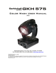
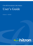
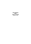
USER MANUAL
Flare software version 8.2
PRELIMINARY
Solaris FLARE user manual version 8.3.8
020513 PRELIMINARY
1
TABLE OF CONTENTS
1. BEFORE YOU BEGIN ..................................................................................................
Product Overview
What is Included
Unpacking Instructions
Power Requirements
Frequency Setting
Safety Instructions
Technical Features
3
3
3
3
3
3
3
3
2. SETUP .........................................................................................................................
Fuse Replacement
Fixture Linking
DMX Data Cable
Cable Connectors
3-Pin to 5-Pin Conversion Chart
Setting up DMX Serial Data Link
Fixture Mouning / Rigging
5
5
5
5
6
6
7
7
3. OPERATING INSTRUCTIONS ......................................................................................
Control Panel Navigation
Menu Map
Menu Function Description
Basic Mode
Strobe Modes
Strobe-Only Mode
Advanced Modes
Pixel Selection Options
Advanced RGB Strobe DMX
Advacned RBGW Strobe DMX
Manual Function
8
8
9
10
12
13
14
15
17
18
19
20
4. APPENDIX ..................................................................................................................
Basics of DMX Control
Limited Warranty
General Maintenance
Returns for Service
Contact Information
Technical Specifications
22
22
22
23
23
23
24
Important: Read this manual before powering or installing the unit. Follow the safety precautions
listed herein. Observe all warnings in this manual and those printed on the unit.
Solaris FLARE user manual version 8.3.8
020513 PRELIMINARY
2
1. BEFORE YOU BEGIN
PRODUCT OVERVIEW
Solaris LED FLARE is an RGBW combination wash/strobe with 1000 Watts of unprecedented RGBW LED
brightness. The FLARE functions simultaneously as a brilliantly bright Wash and Strobe. One Solaris FLARE
does the job of many conventional LED fixtures, saving setup time and labor. Its multiple LEDs are so powerful
and closely coupled they look like a single giant LED. The sheer power of the FLARE rivals traditional tungsten
DWE stage lamps but without the “dots”.
Mix or bump thousands of colors instantly! Use alone or synchronize multiple units to create large-scale colorchanging strobe effects. The extremely high refresh rate of these versatile, compact RGBW fixtures make them
ideal for TV and film applications, as well as theatre, concert, dance club, and rental applications of all kinds.
Simultaneous color Wash and Strobe in one fixture!
1000 Watt brightness in a single LED Wash/Strobe
Produces powerful “organic” light, like one giant LED
Instantaneous RGBW color mixing
2200Hz refresh rate with over 2,000,000 instantaneous color changes!
Pixel-map feature – 12 discrete individually-controlled LED “zones”
WHAT IS INCLUDED
1 x Solaris LED FLARE
1 x Power cable
User Manual
UNPACKING INSTRUCTIONS
Upon receiptof the fixture, carefully unpack the carton and check the contents (see above) to ensure that all parts
are present and in good condition. Notify the shipper immediately and retain packing material for inspection if
any parts appear damaged from shipping or the carton itself shows signs of mishandling. Save the carton and all
packing materials. In the event that a fixture must be returned to the factory, it is important that the fixture be
returned in the original factory box and packing.
POWER REQUIREMENTS
Before powering the unit, make sure the line voltage is within the range of accepted voltages. This fixture
accommodates 100-240VAC, 50/60Hz. All fixtures must be powered directly from a switched circuit and cannot
be operated with a rheostat (variable resistor) or dimmer circuit, even if the rheostat or dimmer channel is used
solely for a 0-100% switch.
When powered up, FLARE performs a pre-programmed internal test. On initial power-up the factory default
DMX address appears on the display screen and FLARE is ready for operation. After initial power-up, the lastsaved DMX address last saved will appear.
FREQUENCY SETTING
Depending on location, change the Default Frequency setting to match the mains power (e.g. Canada and the
US should be set at 60Hz). Proper frequency setting will ensure minimum amount of visible artifacts when using
FLARE on camera.
Solaris FLARE user manual version 8.3.8
020513 PRELIMINARY
3
SAFETY INSTRUCTIONS
Please read these instructions carefully, which includes important
information about the installation, usage and maintenance of this
product.
●
●
●
●
●
●
●
●
●
●
●
Please keep this User Guide for future reference. If you sell the unit to another user, be sure that they
also receive this instruction booklet.
Always make sure that you are connecting to the proper voltage, and that the line voltage you are
connecting to is not higher than that stated on the decal or rear panel of the fixture.
Make sure there are no flammable materials close to the unit while operating.
Always disconnect from the power source before servicing or replacing fuses and be sure to replace with
same fuse type
Secure the fixture to what you have attached it to using a safety chain.
Maximum ambient temperature (Ta) is (40°C). Do not operate fixture at temperatures higher than this.
In the event of a serious operating problem, stop using the unit immediately. Never try to repair the unit
by yourself. Repairs carried out by an unskilled person can lead to damage or malfunction. Please
contact the nearest authorized technical assistance center. Always use the same type of spare parts.
Do not connect the device to a dimmer pack.
Make sure the power cord is never crimped or damaged.
Never disconnect the power cord by pulling or tugging on the cord.
Avoid direct eye exposure to the light source while it is on.
Caution! There are no user serviceable parts inside the unit. Do not open the housing or attempt any
repairs yourself. In the unlikely event your unit may require service, please contact your distributor.
Technical Features / Description
96 units of RGBW LEDs (10W each), divided in to 1, 2, 3, 4, 6 or 12 pixels
Variable intensity control 0-100% in 8bit or 16bit control modes
Beam spread: 36°
Refresh reate: 1200HZ
Flash Duration control 0-650ms flashes per second
Flash Rate control 0-16.7 Hz (50 Hz) / 0-20 Hz (60 Hz)
Continuous blinder/wash effect
Flash intensity curve selection
User definable fades
LCD control panel display with 4 control buttons
Solaris FLARE user manual version 8.3.8
020513 PRELIMINARY
4
2. SETUP
Disconnect the power cord before replacing a fuse
and always replace with the same type fuse.
FUSE REPLACEMENT
The FLARE uses a 12A 250V slow-blow fuse (5x20mm). To replace fuse:
1. With a screwdriver turn the fuse cap counter-clockwise to remove fuse cap with fuse.
2. Replace fuse attached to fuse cap.
3. Reinsert fuse cap with new fuse and tighten clockwise.
FIXTURE LINKING
A DMX data link is needed to operate one or more fixtures via a DMX-512 lighting console. The combined
number of channels required by all the fixtures on a DMX data link determines the number of fixtures the DMX
data link can support.
Important: Fixtures on a DMX data link must be daisy-chained in one single line. To comply with the EIA485 standard, no more than 32 devices should be connected on one data link. Connecting more than 32
fixtures on one serial data link without the use of a DMX optically-isolated splitter may result in
deterioration of the digital DMX signal.
Maximum recommended DMX data link distance between fixtures: 984 ft. (300 meters).
DMX DATA CABLE
Use a ProPlex® DMX cable or equivalent which meets the specifications for EIA RS-485 applications. Standard
microphone cables cannot transmit DMX data reliably over long distances. The data cable must have the
following characteristics:
2-conductor twisted pair plus a shield
Max. capacitance between conductors – 30 pF/ft.
Max. capacitance between conductor and shield – 55 pF/ft.
Max. resistance of 20 ohms / 1000 ft.
Nominal impedance 100-140 ohms
Solaris FLARE user manual version 8.3.8
020513 PRELIMINARY
5
CABLE CONNECTORS
Cabling must have a male XLR connector on one end and a female XLR connector on the other end.
DMX connector configuration
CAUTION: Do not allow contact between the common and the fixture’s chassis ground. Grounding the
common can cause a ground loop, and your fixture may perform erratically. Test cables with an ohm
meter to verify correct polarity and to make sure the pins are not grounded or shorted to the shield or
each other.
3-PIN TO 5-PIN CONVERSION CHART
If you use a console with a 3-pin DMX output connector, use a 3-pin to 5-pin adapter. The chart below details a
proper conversion:
3-Pin Male
(Input)
5-Pin Male
(Output)
Purpose
Pin 1
Pin 1
Ground / Shield
Pin 2
Pin 2
Data ( - ) signal
Pin 3
Pin 3
Data ( + ) signal
Pin 4
Not Used
Pin 5
Not Used
Solaris FLARE user manual version 8.3.8
020513 PRELIMINARY
6
SETTING UP A DMX SERIAL DATA LINK
1) Connect the male 5-pin XLR connector of the data cable to the female 5-pin XLR output of the DMX console.
Connect the other end of the data cable (female 5-pin XLR) to the male 5-pin XLR connector located on the
Solaris FLARE.
2) Connect from the fixture output as stated above to the input of the following fixture, and so forth.
3) Continue linking until the last fixture is conected in your DMX signal data chain.
FIXTURE MOUNTING
Orientation
FLARE fixtures may be mounted in any position. Always make sure there is adequate room for ventilation. Do
not obstruct unit’s fan or vents.
Support Stand
Always use a professional stand rated to support weight greater than the Solaris FLARE weight (14.3 lb / 6.5 kg).
Attach a TVMP spigot to the yoke of the Solaris FLARE and mount on the stand.
Rigging
®
Use a ProBurger coupler or equivalent C- or O-type clamp for attaching to truss. It is important never to
obstruct the fan or vents pathway. Adjust the angle of the fixture by loosening both knobs and tilting the fixture.
After finding the desired position, retighten both knobs.
When selecting installation location, consider lamp replacement access and
routine maintenance.
Safety cables must always be used.
Never mount fixture where it will be exposed to moisture, high humidity, extreme
temperatures, or restricted ventilation.
Solaris FLARE user manual version 8.3.8
020513 PRELIMINARY
7
3. OPERATING INSTRUCTIONS
CONTROL PANEL NAVIGATION
Access control panel functions using the four control panel buttons located directly underneath the LCD Display.
The Control Panel LCD Display shows the menu items selected from the menu map (see page 9). When a
menu function is selected, the display will show the first available option for the selected menu function. To
select a menu item, press <MENU>.
Press and hold the <MENU> button to scroll through the top level menu items. This is the top of the menu map.
Use the <UP> and <DOWN> buttons, located right from LCD screen, to navigate the menu map and menu
options. Press the <MENU> button to access the menu function currently displayed or to enable a menu option.
To return to the top of the menu map or menu without changing the value, press the < X > button.
Main Menu Functions:
DMX Address – DMX address selection
Control – Control mode selection menu
Manual – Manual Control
Demo – Demonstration scenes
Config – Configuratio Menu
During normal operation, the Control Panel LED Display indicates DMX start address. When the DMX signal is
not connected, or if the FLARE is not recieving a DMX signal, the address blinks RED.
Solaris FLARE user manual version 8.3.8
020513 PRELIMINARY
8
MENU MAP
Solaris FLARE user manual version 8.3.8
020513 PRELIMINARY
9
MENU FUNCTION DESCRIPTION
DMX Address – To set the required DMX address, open the Main Menu:
1) Press and hold <MENU> button to open the Main Menu.
2) Use <up> and <down> buttons to find the DMX address function.
3) Press <Select> button to access the DMX address value change submenu.
4) Use <up> and <down> buttons to set necessary DMX address value (e.g. 198 DMX address).
5) Use <Select> button to confirm new DMX address.
6) When the new DMX address is confirmed, return to Main Menu. Press <EXIT> button to return fixture at workstate.
7) The work-state control panel display shows current DMX address, in this case it is 198. Additional info is
displayed under the DMX address: selected control mode, channels used by this mode, and occupied DMX
addresses (DMX footprint.)
In this case MODE: RGB pix:1 (10ch) DMX footprint: 198 - 202 (meaning: RGB control mode with 1 pixel
using 10 dmx channels uses DMX 198 to 202).
Solaris FLARE user manual version 8.3.8
020513 PRELIMINARY
10
Control – FLARE control mode selection. The FLARE includes two fixtures (a strobe type fixture, and a
wash/blinder type fixture) which can combined to suit your needs. In each of the control modes, the fixture
occupies different amounts of DMX channels and has different control channels. To enter the Control submenu,
follow these steps:
1) Press and hold <MENU> button to open the Main Menu.
2) Use <up> and <down> buttons to find the Control submenu.
3) Press <Select> button to access the Control submenu.
4) Choose the correct Control Mode type. Basic or Advanced..
Solaris FLARE user manual version 8.3.8
020513 PRELIMINARY
11
When the Control submenu is opened, there are two settings:
Basic – This mode allows for simple control of the FLARE as a Blinder/Wash fixture, or as a Strobe.
Advanced – This mode allows for independant control of the FLARE Blinder/Wash functions, and the Strobing
functions This mode also allows for independant color and intensity control of every segment of LEDs
independantly.
BASIC MODE
In Basic Mode, you have the option of using the fixture as a wash/blinder, generic strobe, or color strobe.
The first modes are the RGB and RGBW modes in either 8bit resolution or 16bit resolution.
The RGB modes are designed to automatically adjust the white LEDS according to the RGB mix coming from the
lighting controller.
The RGBW modes are designed to give independant control of all 4 colors.
8 bit control uses one DMX channel for each color, and 16 bit control allows for two DMX channels of control to
give the lighting controller more steps of dimming.
Mode
RGB
8bit
RGB
16bit
Channel
DMX values
Precent
1
0 - 255
0 - 100
Red Intensity
2
0 - 255
0 - 100
Green Intensity
3
1
0 - 255
0 - 255
0 - 100
0 - 100
Blue Intensity
Red Intensity HI Byte
2
0 - 255
0 - 100
Red Intensity LOW Byte
3
0 - 255
0 - 100
Green Intensity HI Byte
4
0 - 255
0 - 100
Green Intensity LOW Byte
5
0 - 255
0 - 100
Blue Intensity HI Byte
6
0 - 255
0 - 100
Blue Intensity LOW Byte
Solaris FLARE user manual version 8.3.8
Function
020513 PRELIMINARY
12
Mode
Channel
DMX values
Precent
1
0 - 255
0 - 100
Red Intensity
2
0 - 255
0 - 100
Green Intensity
3
0 - 255
0 - 100
Blue Intensity
4
1
2
0 - 255
0 - 255
0 - 255
0 - 100
0 - 100
0 - 100
White Intensity
Red Intensity HI Byte
Red Intensity LOW Byte
3
0 - 255
0 - 100
Green Intensity HI Byte
4
0 - 255
0 - 100
Green Intensity LOW Byte
5
0 - 255
0 - 100
Blue Intensity HI Byte
6
0 - 255
0 - 100
Blue Intensity LOW Byte
7
0 - 255
0 - 100
White Intensity HI Byte
8
0 - 255
0 - 100
White Intensity LOW Byte
RGBW
8bit
RGBW
16bit
Function
STROBE MODES
Four channels control the functions of the strobe parameter: Strobe Intensity, Strobe Duration, Strobe Rate and
Strobe FX.
DMX
Values
Precent
0-5
6 - 255
0-1
2 - 100
Second
Strobe
Channel
Blackout
Intensity level
Flash duration
0 - 255
0 - 100
Third
Strobe
Channel
0 - 650 ms (50Hz AC)
0 - 530 ms (60Hz AC)
Flash rate
0-5
6 - 255
0-1
2 - 100
No flash
0.5 - 25 Hz (50Hz AC)
0.6 - 30 Hz (60Hz AC)
Flash effects
0-4
5
0-1
2
6 - 42
43 - 85
3 - 16
17 - 33
Ramp up
Ramp down
86 - 128
129 - 171
172 - 214
34 - 50
51 - 67
68 - 84
Ramp up - down
Random
Lighting
215 - 255
85 - 100
Spikes
Channel
First
Strobe
Channel
Fourth
Strobe
Channel
Strobe Function
Flash intensity
No effect
DMX Wash/Blinder Overide
Solaris FLARE user manual version 8.3.8
020513 PRELIMINARY
13
Mode
RGB
Strobe
RGBW
Strobe
1
DMX
values
0 - 255
2
Channel
Precent
Function
0 - 100
Red Strobe Intensity
0 - 255
0 - 100
Green Strobe Intensity
3
0 - 255
0 - 100
Blue Strobe Intensity
4
0 - 255
0 - 100
Strobe Intensity
5
0 - 255
0 - 100
Strobe Duration
6
0 - 255
0 - 100
Strobe Rate
7
0 - 255
0 - 100
Strobe FX
1
0 - 255
0 - 100
Red Strobe Intensity
2
0 - 255
0 - 100
Green Strobe Intensity
3
0 - 255
0 - 100
Blue Strobe Intensity
4
0 - 255
0 - 100
White Strobe Intensity
5
0 - 255
0 - 100
6
0 - 255
0 - 100
Strobe Intensity
Strobe Duration
7
0 - 255
0 - 100
Strobe Rate
8
0 - 255
0 - 100
Strobe FX
Note: In RGB Strobe and RGBW Strobe modes, a feature in the Strobe FX channel allows the FLARE to
become a temporary wash/blinder fixture. If you set the Strobe FX channel to DMX value 5, the Strobe
color Channels become strobe wash/blinder color channels.
For example, the FLARE can be strobing in White, and then quickly changed to a Blue Wash fixture.
White strobing: Strobe Color Channels @ DMX 255, Strobing channels as desired.
Blue Wash: Strobe Color channels to Blue-only @ DMX 255, Strobe FX @ DMX 5, the other strobe channels
are ignored.
STROBE-ONLY MODE
In this mode, the fixture can act as a generic 4 channel Strobe.
In this mode you can select your strobe color after selecting this mode.
Solaris FLARE user manual version 8.3.8
020513 PRELIMINARY
14
Strobe Only
Mode
1
0 - 255
0 - 100
Strobe Intensity
2
0 - 255
0 - 100
Strobe Duration
3
0 - 255
0 - 100
Strobe Rate
4
0 - 255
0 - 100
Strobe FX
ADVANCED MODES
This control submenu setup is for advanced users allowing control of both Strobe Color and Strobe
Intensity/Duration/Rate/FX independantly of Wash/Blinder background color. This also allows independant
control individual segments of 8 LEDs in the array.
You have the choice of either RGB or RGBW control over the color, and how many segments you wish to divide
the fixture into.
The LED segments are comprised of 8 LEDs. There are two sgements of 8 LEDs per row. There are 6 rows of
LEDs, for a total of 12 controllable segments. The more segments chosen, the more sets of RGB or RGBW
follow the Strobe Color and Strobe Control channels.
Choose how many sections (PIXELS) of control after choosing color mode (RGB or RGBW).
Solaris FLARE user manual version 8.3.8
020513 PRELIMINARY
15
Solaris FLARE user manual version 8.3.8
020513 PRELIMINARY
16
PIXEL SELECTION OPTIONS
There are 8 options for subdividing the fixture. Some applications may require less subdivisions than others,
allowing allows the operator to patch the least amount of channels for the application
1
2V
2H
3
1
1
1
1
1
1
1
1
1
2
2
2
1
1
3
4
1
1
3
4
1
1
3
4
1
1
1
1
2
2
2
2
1
1
3
3
2
2
4
4
1
1
2
2
5
5
6
6
1
1
1
1
1
1
3
2
2
4
2
2
2
2
5
6
1
1
1
2
4
6V
1
2
6H
12
1
2
1
2
3
5
4
6
2
2
7
8
3
3
9
10
3
3
11
12
Note: Only the entire fixture can be Strobed. Operators can chase individual sections with intensity or
color very quickly to simulate strobing of individual segments, however, Strobe functions and Strobe
color can only be set for the whole fixture.
Solaris FLARE user manual version 8.3.8
020513 PRELIMINARY
17
ADVANCED RGB STROBE DMX CHANNELS
PIXEL MODE
RGB
PIXEL
MODE 1
RGB PIXEL
MODE 2
RGB PIXEL
MODE 3
RGB PIXEL
MODE 4
RGB PIXEL
MODE
6H or 6V
RGB PIXEL
MODE 12
CHANNEL
DMX VALUE
PERCENT
1
0 - 255
0 - 100
Red Strobe Intensity
2
0 - 255
0 - 100
Green Strobe Intensity
3
0 - 255
0 - 100
Blue Strobe Intensity
4
0 - 255
0 - 100
Strobe Intensity
5
0 - 255
0 - 100
Strobe Duration
6
0 - 255
0 - 100
Strobe Rate
7
0 - 255
0 - 100
Strobe FX
8
0 - 255
0 - 100
1 pix Red intensity
9
0 - 255
0 - 100
1 pix Green intensity
10
0 - 255
0 - 100
1 pix Blue intensity
11
0 - 255
0 - 100
2 pix Red intensity
12
0 - 255
0 - 100
2 pix Green intensity
13
0 - 255
0 - 100
2 pix Blue intensity
14
0 - 255
0 - 100
3 pix Red intensity
15
0 - 255
0 - 100
3 pix Green intensity
16
0 - 255
0 - 100
3 pix Blue intensity
17
0 - 255
0 - 100
4 pix Red intensity
18
0 - 255
0 - 100
4 pix Green intensity
19
0 - 255
0 - 100
4 pix Blue intensity
20
0 - 255
0 - 100
5 pix Red intensity
21
0 - 255
0 - 100
5 pix Green intensity
22
0 - 255
0 - 100
5 pix Blue intensity
23
0 - 255
0 - 100
6 pix Red intensity
24
0 - 255
0 - 100
6 pix Green intensity
25
0 - 255
0 - 100
6 pix Blue intensity
26
0 - 255
0 - 100
7 pix Red intensity
27
0 - 255
0 - 100
7 pix Green intensity
28
0 - 255
0 - 100
7 pix Blue intensity
29
0 - 255
0 - 100
8 pix Red intensity
30
0 - 255
0 - 100
8 pix Green intensity
31
0 - 255
0 - 100
8 pix Blue intensity
32
0 - 255
0 - 100
9 pix Red intensity
33
0 - 255
0 - 100
9 pix Green intensity
34
0 - 255
0 - 100
9 pix Blue intensity
35
0 - 255
0 - 100
10 pix Red intensity
36
0 - 255
0 - 100
10 pix Green intensity
37
0 - 255
0 - 100
10 pix Blue intensity
38
0 - 255
0 - 100
11 pix Red intensity
39
0 - 255
0 - 100
11 pix Green intensity
40
0 - 255
0 - 100
11 pix Blue intensity
41
0 - 255
0 - 100
12 pix Red intensity
42
0 - 255
0 - 100
12 pix Green intensity
43
0 - 255
0 - 100
12 pix Blue intensity
Solaris FLARE user manual version 8.3.8
FUNCTION
020513 PRELIMINARY
18
ADVANCED RGBW STROBE DMX CHANNELS
PIXEL MODE
RGBW PIXEL
MODE 1
RGBW PIXEL
MODE
2V
or 2H
RGBW PIXEL
MODE 3
RGBW PIXEL
MODE 4
RGBW PIXEL
MODE
6H
or 6V
RGBW PIXEL
MODE 12
CHANNEL
DMX VALUE
PERCENT
1
0 - 255
0 - 100
Red Strobe Intensity
2
0 - 255
0 - 100
Green Strobe Intensity
3
0 - 255
0 - 100
Blue Strobe Intensity
4
0 - 255
0 - 100
White Strobe Intensity
5
0 - 255
0 - 100
Strobe Intensity
6
0 - 255
0 - 100
Strobe Duration
7
0 - 255
0 - 100
Strobe Rate
8
0 - 255
0 - 100
Strobe FX
9
0 - 255
0 - 100
1 pix Red intensity
10
0 - 255
0 - 100
1 pix Green intensity
11
0 - 255
0 - 100
1 pix Blue intensity
12
0 - 255
0 - 100
1 pix White intensity
13
0 - 255
0 - 100
2 pix Red intensity
14
0 - 255
0 - 100
2 pix Green intensity
15
0 - 255
0 - 100
2 pix Blue intensity
16
0 - 255
0 - 100
2 pix White intensity
17
0 - 255
0 - 100
3 pix Red intensity
18
0 - 255
0 - 100
3 pix Green intensity
19
0 - 255
0 - 100
3 pix Blue intensity
20
0 - 255
0 - 100
3 pix White intensity
21
0 - 255
0 - 100
4 pix Red intensity
22
0 - 255
0 - 100
4 pix Green intensity
23
0 - 255
0 - 100
4 pix Blue intensity
24
0 - 255
0 - 100
4 pix White intensity
25
0 - 255
0 - 100
5 pix Red intensity
26
0 - 255
0 - 100
5 pix Green intensity
27
0 - 255
0 - 100
5 pix Blue intensity
28
0 - 255
0 - 100
5 pix White intensity
29
0 - 255
0 - 100
6 pix Red intensity
30
0 - 255
0 - 100
6 pix Green intensity
31
0 - 255
0 - 100
6 pix Blue intensity
32
0 - 255
0 - 100
6 pix White intensity
33
0 - 255
0 - 100
7 pix Red intensity
34
0 - 255
0 - 100
7 pix Green intensity
35
0 - 255
0 - 100
7 pix Blue intensity
36
0 - 255
0 - 100
7 pix White intensity
37
0 - 255
0 - 100
8 pix Red intensity
38
0 - 255
0 - 100
8 pix Green intensity
39
0 - 255
0 - 100
8 pix Blue intensity
40
0 - 255
0 - 100
8 pix White intensity
41
0 - 255
0 - 100
9 pix Red intensity
42
0 - 255
0 - 100
9 pix Green intensity
43
0 - 255
0 - 100
9 pix Blue intensity
44
0 - 255
0 - 100
9 pix White intensity
45
0 - 255
0 - 100
10 pix Red intensity
Solaris FLARE user manual version 8.3.8
020513 PRELIMINARY
FUNCTION
19
46
0 - 255
0 - 100
10 pix Green intensity
47
0 - 255
0 - 100
10 pix Blue intensity
48
0 - 255
0 - 100
10 pix White intensity
49
0 - 255
0 - 100
11 pix Red intensity
50
0 - 255
0 - 100
11 pix Green intensity
51
0 - 255
0 - 100
11 pix Blue intensity
52
0 - 255
0 - 100
11 pix White intensity
53
0 - 255
0 - 100
12 pix Red intensity
54
0 - 255
0 - 100
12 pix Green intensity
55
0 - 255
0 - 100
12 pix Blue intensity
56
0 - 255
0 - 100
12 pix White intensity
MANUAL FUNCTION
This menu function allows selection of the intensity of wash/blinder background color, strobe color, and strobe
functions. This functions as a stand-alone mode. Manual values are saved if power is shut down. A reset will
clear these values (see Menu Map, page 9).
Demo – In this menu the folowing demonstraton scenes may be selected:
Demo 1 - Red color test
Demo 2 - Green color test
Demo 3 - Blue color test
Demo 4 - White color test
Demo 5 - Yellow color test
Demo 6 - Cyan color test
Demo 7 - Magenta color test
Demo 8 - White (RGB) color test
Demo 9 - Color Amplitude Modulation,
blure edge transition test
Demo 10 - Color Amplitude Modulation, hard
edge transition test
Demo 11 - Color + Intensity Amplitude Modulation
test
Demo 12 - Color Intensity Amplitude Modulation
test with hard edges
Demo 13 - White Intensity Amplitude Modulation
test
Demo 14 - Red color strobe test
Demo 15 - Green color strobe test
Demo 16 - Blue color strobe test
Demo 17 - White flash delay test
Demo 18 - Red flash delay test
Demo 19 - Green flash delay test
Demo 20 - Blue flash delay test
Demo 21 – White Fast Flash
Auto 1 - Automatic selection of all
demonstrations (Demo 1 – Demo 21)
During the demo functions, using the <UP> and <DOWN> buttons will change the demo scenes. To exit Demo
mode, press the < X > button. This mode works as a stand-alone mode, even if the FLARE is turned off and then
back on, the selected demo scene will be saved. While in the Demo menu, the demonstration scene will play.
When you exit from Demo mode, the FLAR will return to a normal state of operation.
Config – Configuration setup. In this menu, the folowing functons may be selected:
DMX LOSS – Select desired function should the FLARE lose DMX signal:
HOLD – Hold the last received DMX values when DMX signal is lost
OFF – Do not hold the last received DMX values when DMX signal is lost, stop light output.
Fan – Cooling Fan:
AUTO – Fan speed is automatically controlled by the FLARE and will adjust according to temperatures
at normal operating levels.
ON – Fan cooling always is turned on.
Solaris FLARE user manual version 8.3.8
020513 PRELIMINARY
20
Display – Automatic power on/off:
ON – Control display is turned on.
10s – Control display is turned off after 10 seconds of inactivity.
30s – Control display is turned off after 30 seconds of inactivity..
Thermometer – Internal temperature gauge:
The built-in thermometer tracks internal operating temperature. Pressing the <UP> and <DOWN>
buttons selects degrees Celsius to degrees Fahrenheit.
Fade Time – Fade time setup. In this setup the operator can set the way the FLARE reacts to changing DMX
values. This is designed to allow the light output of the FLARE to react as smoothly as possible when
crossfading DMX values.
OFF – The FLARE will not change the smoothness of crossfading of values coming from the lighting
controller
Smart Fade – The FLARE will attempt to add smoothness to crossfading DMX values coming from the
lighting controller, but will also allow for very quick change of values where smoothness is not applicable.
Fixed Fade – The fade time for any change in DMX values can be set manually. The timing values can
be set from 0.01 to 2.50 seconds. Use the <UP> and <DOWN> buttons to change these values.
Gamma – Gamma correction curve selection. This sets direct relation between AC current to the LEDs and the
DMX value. The lower the value, the dimming curve and steps of intensity will be more noticeable at the bottom
of the DMX range. The higher the value, the smoother the bottom end of the curve will be where the human eye
detects more subtle changes.
Gamma 8 – 8-bit rate Gamma correction setup. Color dimming curve values can be set from 1.0 to 5.0.
The default value is 3.0
Gamma 16 – 16-bit rate Gamma correction setup. Each color dimming curve values from 1.0 to 5.0.
The default value is 1.0
Upload – Upload software. Designed to cross-load software from one FLARE to others in the DMX data chain.
This should not be used when other fixture types are in the data chain. Use of this function will be prompted by
Password. The password is 111.
Line Freq – Line Frequency. Allows adjustment of FLARE input power frequency to match local source power
for minimum visual artifacts on camera. The setting depends on region of use and power source. There are two
options: 50Hz and 60Hz. Use the <UP> and <DOWN> buttons to change these values.
Reset – Set factory defaults. Two options: NO and YES. Use the <UP> and <DOWN> buttons to change these
values.
Solaris FLARE user manual version 8.3.8
020513 PRELIMINARY
21
4. APPENDIX
BASICS OF DMX CONTROL
There are 512 channels in a DMX-512 connection. Channels may be assigned in any manner. A fixture capable
of receiving DMX-512 will require one or a number of sequential channels. The user must assign a starting
address on the fixture that indicates the first channel reserved in the lighting console. There are many different
types of DMX controllable fixtures and they all may vary in the total number of channels required. Choosing a
start address should be planned in advance. Channels should never overlap. If they do, this will result in erratic
operation of the fixtures whose starting addresses are set incorrectly. You can however, control multiple fixtures
of the same type using the same starting address as long as the intended result is that of unison movement or
operation. In other words, the fixtures will be slaved together and all will respond in the same way.
DMX fixtures are often designed to receive and transmit data through a DMX daisy-chain. A DMX daisy-chain is
where the DMX OUT of one fixture connects to the DMX IN of the next fixture. The order in which the fixtures are
connected is not important and has no effect on how a lighting console communicates to each fixture. Use an
order that provides for the easiest and most direct cabling. Connect fixtures using shielded two conductor twisted
pair cable with 5-pin XLR male to female connectors. The shield/ground is pin 1, while pin 2 is Data Negative
(D-) and pin 3 is Data positive (D+). Pins 4 and 5 are not used according to the DMX-512 standard.
LIMITED WARRANTY
ProPlex Data Distribution Devices are warranted against defective materials or workmanship for a period of 12
months from the date of shipment.
Parts and components that are not the product of the Seller (TMB) shall be subject only to the terms of any
warranty that may be extended by the original manufacturer. Seller’s warranty shall be restricted to the repair or
replacement of any part that proved to be defective and for which a claim is submitted to the Seller before the
expiration of the applicable warranty periods.
This warranty shall not apply to any defect arising from accident, misuse or improper or unauthorized adjustment
or repair. No warranty is given with respect to color media or lamps, or with respect to normal wear and tear.
Any claim for defective merchandise, imperfect manufacture, shortage in count, or for any other defect known by
the Customer to be existing at time of delivery is waived by the Customer unless made in writing within 30 days
after delivery.
All warranty parts will be charged to the customer until faulty parts (or product) are returned to TMB for valuation.
These parts must be returned within 30 days of receipt or warranty is void and parts/shipping become billable
items.
Seller will not assume any responsibility for any labor expended or materials used to replace and/or repair any
equipment without Seller’s prior written authorization. Any labor charges for repairing or replacing equipment in
the field will be negotiated only between the Seller and general contractor. Freight terms on warranty repairs are
FOB Seller’s warehouse or factory. If warranty parts and/or repairs are required, Seller agrees to pay destination
ground freight charges on the aforementioned items leaving the Seller’s facility.
GENERAL MAINTENANCE
To maintain optimum performance and minimize wear fixtures should be cleaned frequently. Usage and
environment are contributing factors in determining frequency. As a general rule, fixtures should be cleaned at
least twice a month. Dust build up reduces light output performance and can cause overheating. This can lead
Solaris FLARE user manual version 8.3.8
020513 PRELIMINARY
22
to reduced lamp life and increased mechanical wear. Be sure to power off fixture before conducting
maintenance.
Unplug fixture from power. Use a vacuum or air compressor and a soft brush to remove dust
collected on external vents and internal components. Clean all glass when the fixture is cold with a mild solution
of glass cleaner or Isopropyl Alcohol and a soft lint free cotton cloth or lens tissue. Apply solution to the cloth or
tissue and drag dirt and grime to the outside of the lens. Gently polish optical surfaces until they are free of haze
and lint.
The cleaning of internal and external optical lenses and/or mirrors must be carried out periodically to optimize
light output. Cleaning frequency depends on the environment in which the fixture operates: damp, smoky or
particularly dirty surrounding can cause greater accumulation of dirt on the unit’s optics. Clean with soft cloth
using normal glass cleaning fluid. Always dry the parts carefully. Clean the external optics at least every 20
days. Clean the internal optics at least every 30 / 60 days.
RETURN PROCEDURE
Returned merchandise must be sent prepaid and in the original packing, call tags will not be issued. Package
must be clearly labeled with a Return Merchandise Authorization Number (RMA #). Products returned without an
RMA # will be refused. Please contact TMB and request RMA # prior to shipping the fixture. Be prepared to
provide the model number, serial number and a brief description of the cause for the return. Be sure to properly
pack fixture, any shipping damage resulting from inadequate packaging is the customer’s responsibility. TMB
reserves the right to use its own discretion to repair or replace product(s). As a suggestion, proper UPS packing
or double-boxing is always a safe method to use.
Note: If you are given an RMA#, please include the following information on a piece of paper inside the
box:
1) Your name
2) Your address
3) Your phone number
4) The RMA #
5) A brief description of the symptoms
CONTACT INFORMATION
GENERAL INFORMATION
TMB
US Phone:
Fax:
UK Phone:
Fax:
e-mail:
web:
+1 818.899.8818
+1 818.899.8813
+44 (0)20.8574.9700
+44 (0)20.8574.9701
tmb-info@tmb.com
www.tmb.com
24/7 TECHNICAL SUPPORT
TMB
US/Canada:
Toll-free UK:
International:
e-mail:
1 877.TMB.DUDE (+1 877.862.3833)
0800.652.5418
+1 818.794.1286
techsupport@tmb.com
Solaris FLARE user manual version 8.3.8
020513 PRELIMINARY
23
TECHNICAL SPECIFICATIONS
WEIGHT / DIMENSIONS
Length .................................................................................................... 19.5” (497mm)
Width .................................................................................................... 8.26” (210mm)
Height ...................................................................................................... 9.1” (232mm)
Weight .................................................................................................... 14.3 lb (6.5 kg)
POWER
Operating Voltage ......................................................................... 100-240VAC 50/60Hz
Fuse.................................................................................12A 250V slow-blow (5x20mm)
Power Consumption ............................................................................................ 1000W
LIGHT SOURCE
LED's............................ 96 units Cree MC-E LED's (10W ea.) divided into 12 segments
Color .................................................................................................................... RGBW
Beam spread ............................................................................................................. 36°
THERMAL
Max. ambient temperature.......................................................................+104°F (+40°C)
Min. ambient temperature........................ ...................................................-77°F (-25°C)
Cooling ............................................... ................................................... air cooled – fan
CONTROL / PROGRAMMING
DMX input ....................................................................... locking 5-pin XLR male socket
DMX output .................................................................. locking 5-pin XLR female socket
DMX pin config. .............................. pin 1 shield, pin 2 (-), pin 3 (+), pin 4 n/a, pin 5 n/a
Control .........................................................................DMX-512 , Demo, Manual mode
DMX Channels – Basic Mode............................................................................3,4,6,7,8
DMX Channels - Blind Mode...................................... 10,12,13,16,19,20,24,25,32,43,56
Power Connector ......................................................................... Input: powerCON 20A
Solaris FLARE user manual version 8.3.8
020513 PRELIMINARY
24