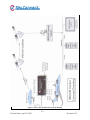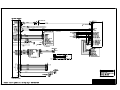
1
Sky Connect Series Installation Manual
Revision #2.02
Dated: April 25, 2005
i
Revision Date: April 25, 2005
Revision 2.02
TABLE OF CONTENTS
LIST OF REVISIONS........................................................................................................................................IV
INDEX OF ACRONYMS.................................................................................................................................... V
1
GENERAL INFORMATION ..................................................................................................................1-1
1
2
GENERAL ............................................................................................................................................1-1
1.1.
INTRODUCTION.........................................................................................................................1-1
1.2
SYSTEM DESCRIPTION ..............................................................................................................1-1
1.3
TECHNICAL SPECIFICATIONS..................................................................................................1-3
INSTALLATION PROCESS...................................................................................................................2-1
1.
INSTALLATION PLANNING ..............................................................................................................2-1
1.1.
Wiring diagram ............................................................................................................................2-1
1.2.
SIM card activation ......................................................................................................................2-1
1.3.
Antenna placement plan................................................................................................................2-1
2.
WIRING................................................................................................................................................2-1
3.
CONFIGURATION ..............................................................................................................................2-2
3
INSTALLATION - GENERAL ...............................................................................................................3-1
PRIOR TO INSTALLATION .........................................................................................................................3-1
A DISCUSSION ON SIM CARDS..................................................................................................................3-1
SIM PIN REMOVAL (ALL SYSTEMS) .................................................................................................................3-1
GENERAL SYSTEM COMPONENTS THAT APPLY TO ALL SYSTEMS....................................................3-2
GENERAL INSTALLATION INSTRUCTIONS.............................................................................................3-3
1.
ANTENNA PLACEMENT..................................................................................................................3-3
2.
ANTENNA CABLE............................................................................................................................3-3
3.
TRANSCEIVER STRUCTURAL MOUTING.......................................................................................3-4
4.
TRANSCEIVER ELECTRICAL INSTALLATION................................................................................3-4
TRANSCEIVER PIN ASSIGNMENTS .........................................................................................................3-5
4
EXECUTIVE SYSTEM ...........................................................................................................................4-1
1.
INSTALLATION .................................................................................................................................. 4-1
1.1.
EXECUTIVE SYSTEM COMPONENTS ........................................................................................4-1
1.2.
EXECUTIVE COMPONENT SPECIFICATIONS ..........................................................................4-3
1.3.
EXECUTIVE STRUCTURAL MOUNTING....................................................................................4-3
1.4.
WIRING .......................................................................................................................................4-4
2.
POST INSTALLATION TESTING........................................................................................................4-4
2.1.
TRANSCEIVER INDICATIONS, PHONE SETTINGS AND OPERATIONS....................................4-4
2.3.
RESETTING BASE STATION .......................................................................................................4-5
2.5.
TROUBLESHOOTING TIPS.........................................................................................................4-6
3.
OPERATIONS ......................................................................................................................................4-7
5
FLIGHTDECK SYSTEM ........................................................................................................................5-1
1.
INSTALLATION .................................................................................................................................. 5-1
1.1.
FLIGHTDECK SYSTEM COMPONENTS.....................................................................................5-1
1.2.
FLIGHTDECK COMPONENT SPECIFICATIONS (USING NAT PTA12 DIALPAD) ....................5-2
1.3
FLIGHTDECK STRUCTURAL MOUNTING ................................................................................ 5-2
1.4
FLIGHTDECK SYSTEM WIRING.................................................................................................5-2
2
POST INSTALLATION TESTING........................................................................................................5-3
2.1.
TRANSCEIVER INDICATIONS AND PHONE SETTINGS ............................................................5-3
2.3.
TROUBLESHOOTING TIPS.........................................................................................................5-3
3.
OPERATIONS ......................................................................................................................................5-4
ii
Revision Date: April 25, 2005
Revision 2.02
6
CLASSIC SYSTEM .................................................................................................................................6-1
1.
INSTALLATION .................................................................................................................................. 6-1
1.1.
CLASSIC SYSTEM COMPONENTS..............................................................................................6-1
1.2.
CLASSIC COMPONENT SPECIFICATIONS................................................................................ 6-2
1.3.
CLASSIC STRUCTURAL MOUNTING .........................................................................................6-2
1.4.
CLASSIC WIRING........................................................................................................................6-3
2.
POST INSTALLATION TESTING........................................................................................................6-3
2.1
TRANSCEIVER INDICATIONS, PHONE SETTINGS AND OPERATIONS....................................6-3
2.2.
HOW TO DIAL CALLS.................................................................................................................6-3
2.3.
TROUBLESHOOTING TIPS.........................................................................................................6-4
3.
OPERATIONS ......................................................................................................................................6-4
7
TRACKER SYSTEM...............................................................................................................................7-1
1.
INSTALLATION .................................................................................................................................. 7-1
1.1.
TRACKER SYSTEM COMPONENTS............................................................................................7-1
1.2.
TRACKER-SOP COMPONENT SPECIFICATIONS......................................................................7-2
1.3
TRACKER-SOP STRUCTURAL MOUNTING ...............................................................................7-3
1.4
TRACKER WIRING......................................................................................................................7-3
2.
POST INSTALLATION TESTING........................................................................................................7-3
2.1
TRACKER SETUP........................................................................................................................ 7-4
2.2
CONFIGURATION SETTINGS.................................................................................................... 7-5
2.4.
TRACKER TESTING .................................................................................................................. 7-10
3.
OPERATION ...................................................................................................................................... 7-12
3.1.
TRACKER .................................................................................................................................. 7-12
3.2.
TRACKER SOP
................................................................................................................... 7-12
8
TELEPHONE INDICATIONS AND SETUP..........................................................................................8-1
1.
2
9
TRANSCEIVER INDICATIONS ..........................................................................................................8-1
PHONE TESTING ................................................................................................................................8-2
2.1.
AIRCRAFT TO GROUND.............................................................................................................8-2
2.2.
GROUND TO AIRCRAFT.............................................................................................................8-2
APPENDIX A TROUBLESHOOTING...................................................................................................9-1
iii
Revision Date: April 25, 2005
Revision 2.02
LIST OF REVISIONS
Revision #
2.0
2.01
2.02
Description of Change
Manual re-write
Typo corrections and added info on A model LBT
Change on SOP Dialer dimming
Date
3/24/2005
4/8/2005
4/25/05
Approval
MLF
MLF
MLF
iv
Revision Date: April 25, 2005
Revision 2.02
INDEX OF ACRONYMS
FOI
GIS
IDT
IMEI
LBT
PBX
POTS
PUK
SBD
SIM
SMS
Field Of Interest (a position)
Geographic Information System
Icarus Dial Tone
International Mobile Equipment Identifier
L Band Transceiver
Private Branch eXchange
Plain Old Telephone System
Personal Unblocking Code
Short Burst Data
Subscriber Identity Module
Short Message Service
For a complete definition of terms see http://www.telestial.com/glossary.htm on the Web.
v
Revision Date: April 25, 2005
Revision 2.02
1 GENERAL INFORMATION
1 GENERAL
1.1.
INTRODUCTION
This manual contains information relative to the physical, mechanical, and electrical
installation of the Sky Connect Systems. Operating procedures are also included.
1.2
SYSTEM DESCRIPTION
The Sky Connect series satellite communications device consists of a transceiver, an L-band
antenna, and a dialing/audio/data interface device. The remote mounted transceiver is the
heart of the system, and contains the Iridium satellite LBT (L-Band Transceiver). The LBT
can be thought of as the “phone” in the satellite phone system and the modem in the data
system, as it is the connection used to gain access to the Iridium network. The LBT allows
the two way transfer of voice and data.
The LBT is the same in every transceiver of the Sky Connect System though different
modules are added to define the function of the transceiver as a whole. Phone versions
contain a POTS and/or DSC (DSC in older units only) module allowing the LBT to be dialed
and interfaced with remotely. Each Sky Connect telephone system also has the ability for
data transfer at rates up to 10 Kbps (with compression), allowing the user to interface a
laptop for in-flight email capability, and in a pinch, website browsing. The Tracker system
contains an additional module and offers an optional internal 12 channel GPS module.
Tracker uses the short burst data transfer portions of the Sky Connect suite, though it can be
coupled with any of the phone systems. Any system can exist alone, or co-exist with
another, and upgrades can be done to any system at any time without incurring additional
cost penalties.
The Iridium system can only be occupied by one “call” at a time, whether it is voice, data, or
Short Burst Data. These systems exist simultaneously, but can not be used simultaneously.
Multiple transceivers and antennas are required for multiple channels of communication. For
clarity, two users may be on separate handsets on the same call, but two users can not be on
separate handsets on different calls without a second transceiver/antenna. Similarly, when a
phone call is in progress, Tracker will be unable to send SBD packets, though as soon as the
line is clear, it will send its stored messages.
1-1
Revision Date: April 25, 2005
Revision 2.02
Figure 1 Tracker & Communication Concept Drawing
1-2
Revision Date: April 25, 2005
Revision 2.02
1.3
TECHNICAL SPECIFICATIONS
TRANSCEIVER
Regulatory Compliance:
Temperature Range:
Altitude Range:
Vibration:
Temp Variation:
Power Input:
DC Spike:
Conducted Emissions
Radiated Emissions
Weight (Unit, Rack, and Hardware):
Add Tracker:
Add GPS
Add Messenger:
Physical Dimensions:
(Length)
(Width)
(Height)
Power Requirements (Voltage):
Power Requirements (Current) :
Transmit Power Average:
Transmission rate:
Operating Frequency
Inputs/Outputs:
Connectors:
Mounting:
DO-160D, Initial Part 25 Canadian and American
STC on Cessna 525 (CJ2)
Section 4 Cat D2 (-20C to +55C)
Section 4 Cat D2 (50,000 feet)
Section 8 Cat R
Section 5 Cat C
Section 16 Cat B
Section 17 Cat B
Section 21 Cat B
Section 21 Cat B
4.05 lbs.
.05 lbs.
.10 lbs
.05 lbs.
10.000 Inches
2.500 Inches
4.500 Inches
11-32Vdc
<1 Amp @ 28Vdc
1.5 watts
2.4Kbps voice and data (10Kbps with compression)
1.616-1.6265 GHz
POTS (Plain Old Telephone Service), RS232, DSC,
dc level.
TNC female (Iridium), BNC female GPS,
62 pin High Density D-sub connector
Quick release tray, 4-#6 holes
SYSTEMS COMPONENTS
Refer to individual system sub-sections for specifications on those components specific to
each system.
1-3
Revision Date: April 25, 2005
Revision 2.02
2 INSTALLATION PROCESS
INSTALLATION PROCESS OUTLINE
1. INSTALLATION PLANNING
Note: Make a plan to cover the follow items in depth in this manual.
1.1. Wiring diagram
1.1.1.
1.1.2.
1.1.3.
1.1.4.
1.1.5.
GPS interface, or use of an internal GPS
Event switches, optional
Diagnostic port, must be installed for configuration
Configuration module, optional
Selection of Dialers optional
1.2. SIM card activation
Check to make sure the card is activated, call Sky Connect
You will need to know the following information
1.2.1.
1.2.2.
1.2.3.
1.2.4.
1.2.5.
1.2.6.
The IMEI # of your unit
Model #
Serial #
Credit Card or billing information for monthly service
Aircraft type and registration number
Complete contact information for customer using the product
1.3. Antenna placement plan
1.3.1.
1.3.2.
Pay close attention to the length of coax from the antenna to RT
Follow manual instructions on placement near other Sat COM and Comm antennas
1.4. Notebook computer with “tracker setup” program, CD included with RT
Information that will be needed for configuration
1.4.1.
1.4.2.
1.4.3.
How the event switches were wired
What type of switches, MOM, ALT, Press
What phone numbers need to be entered (optional)
2. WIRING
2.1. Wire system as drawn, you the installer are responsible to the FAA for methods and practices
used during the installation
2.2. Continuity checks
2.3. Power polarity checks
2-1
Revision Date: April 25, 2005
Revision 2.02
3. CONFIGURATION
3.1. Configure RT to work with event switches as connected in wiring
3.2. Configure external GPS to talk to Sky Connect RT, Aviation or NMEA RS232 format data
3.3. Enter phone numbers (optional)
2-2
Revision Date: April 25, 2005
Revision 2.02
3 INSTALLATION - GENERAL
PRIOR TO INSTALLATION
Perform a visual inspection of the equipment for evidence of damage incurred during
shipment.
A DISCUSSION ON SIM CARDS
No testing can occur until a valid SIM card is installed in the transceiver, and the PIN code
turned off. The account has to be activated with an Iridium service provider. Systems are
generally shipped with a SIM card installed, with the PIN code disabled, and the service
active. The customer is responsible for this activation as the customer receives the bills for
the phone use. This process can take a day, and should be done in advance of the
installation/testing. This is why we ask for the activation information at the time of the sale.
In the event that the customer provides a SIM card, it must be de-pinned, or the system will
get blocked. Contact the manufacturer if you intend to change SIM cards. Sky Connect
recommends against customer replacement of SIM cards as it affects unit serviceability.
Until the Iridium L-Band Transceiver has been registered on the network, there is very little
you can do to test its operation. A de-pinned activated SIM is required before this can
happen. The SIM card is the identity of the user, and thus must travel with the user. In this
case, the user’s SIM card is installed in the Sky Connect transceiver.
This process should only need to be accomplished at initial installation. After user
activation, the phone will function. Should the unit need to be replaced, or transferred to
another party, or in the event that a SIM card requires replacement, return unit to Sky
Connect or a qualified avionics shop to have the SIM card replaced in order to keep the SIM
card account matched with the user.
While activation is not required, a valid SIM card must also be installed in
Tracker/Messenger only systems. In addition to the installed SIM card, an IMEI # must be
recorded for customer activation on Tracker only systems. The IMEI# is located on the
outside of the transceiver.
SIM PIN removal (All systems)
If your SIM card has the PIN protection feature enabled, you must enter the PIN code when
prompted. This PIN is normally disabled from the factory, but may be requested on, and will
always be on when a SIM card other than the SIM Sky Connect inserted. On the
Executive/FlightDeck systems, the prompt for the PIN is a melodic three tone sequence.
Enter “*1* PINCODE #”. On a Classic handset, you will be prompted to “Enter Pin.” Do
3-1
Revision Date: April 25, 2005
Revision 2.02
so, and press “OK”. You will be prompted for the PIN each time the system is started unless
the PIN is disabled. This can be done on the classic handset by pressing “Menu,” selecting
“Phone Setup,” “Require SIM Card,” “Off.” Consult factory for disabling instructions
with Executive/FlightDeck systems.
Note: Do not attempt to make a phone call with an active SIM pin. Changing the
SIM card in the field to a different provider’s SIM card necessitates the removal of
the PIN for proper operation. If a PIN is entered incorrectly three times, you will
lock the phone and you will be unable to do any testing until the problem is resolved
by the factory.
Items required but not supplied;
Table 1
QTY.
1
1
1
-
ITEMS
Daniels Manufacturing Crimper P/N M22520/2-01
Daniels Manufacturing Crimper Positioner P/N K41
Daniels Manufacturing Crimper Positioner P/N K1S
Crimping tools for use on coax connectors
Coax connectors for antenna cable if locally made
Misc. installations supplies such as; wire ties, Adel
clamps, Etc.
USE
P1
P1
All M24308 connectors
All coax connectors
GENERAL SYSTEM COMPONENTS THAT APPLY TO ALL SYSTEMS
Table 2
Product
Part Number
Description
Items that apply
1616-700-01
Inmarsat Filter
to all systems
1616-900-99
Sky Connect Series CD ROM
1616-900-95
Apollo Compression Software
1616-900-XX
Aviation Installation Manual, current revision
1616-901-XX
Quick Start User Manual, current revision
1616-050-80
SBD Message Traffic
1616-050-97
Shop Upgrade Harness
1616-050-98
Field Upgrade Harness
1616-104-01
3 year warranty
S67-1575-109
Low Profile Iridium Antenna
1616-900-10
ARINC 429 Converter for converting to RS232
1616-105-02
RT Installation kit which consist of:
1.) AMP HDP-20 Crimp Contact Connectors (P/N
571-2051631) from Mouser Electronics
2.) Connector Pin (P/N FC7520D) from Positronic
Industries
3.) UND Cable Clamp SZ2/AMP D-sub Accessories
(P/N 571-2057301) from Mouser Electronics
4.) Hardware AMP DC 0449 Kit (P/N 205980-1)
from Mouser Electronics
3-2
Revision Date: April 25, 2005
Revision 2.02
GENERAL INSTALLATION INSTRUCTIONS
1.
ANTENNA PLACEMENT
The Aero-Antenna AT2775 L-Band antenna should be placed as far as practical from other
transmitting antennae. A minimum of 30 inches is recommended to other L-Band
transmitting antennae. The Iridium antenna is itself a transmitting antenna, and as such, an
eighteen inch minimum spacing to GPS antennae is recommended. The Iridium antenna
requires full view of the sky above. Shadowing and interference can occur when mounted
near vertical stabilizers, and other structures inherent to aircraft. When used in conjunction
with an internal GPS for Tracker, a separate active Sensor S67-1575-39 GPS antenna is
supplied. See Figure 4 for antenna dimensions.
Note: Inmarsat systems (commonly referred to as Satcom) will greatly interfere
with the performance of the Iridium antenna. This interference may appear to be
intermittent with aircraft position as the Inmarsat transmitting antenna array is
electrically steer able depending on azimuth to satellite. Inmarsat will disrupt
Iridium communications whenever active. Inmarsat should be disabled when
Iridium is in use, alternatively, filters are available for Inmarsat systems which
essentially act as an Iridium bandpass filter. Consult Sky Connect for more
information.
The antenna should be mounted in accordance with the manufacturer’s instructions and
reference FAA AC43.13-2A. The antenna should be properly bonded to the aircraft ground
plane to aid in eliminating unwanted interference. Surface preparation should include the
use of Alodine 1001 or similar. The antennae listed above, as well as the Sensor S67-1575109 Iridium antenna are all TSO’d and approved for mounting on pressurized vessels.
Antenna installations on pressurized vessels require FAA approved design and engineering
data whenever a pressure vessel requires penetration due to connector/mounting holes.
Approved designs can be obtained from aircraft manufacturers, STC data specific to the
antenna, or DERs. Seal antenna in accordance with FAA AC43.13-2A.
2. ANTENNA CABLE
When routing antenna cable, avoid high current wiring, other transmitting antenna cables,
and sharp bends. Antenna cable should be selected to obtain 3dB max loss at 1.6GHz. The
installer is responsible for providing antenna cables. Use the following chart as an aid to
determine the appropriate cable type for your required installed length. Follow industry
practices when assembling the TNC connectors. RG-142 coax cable is recommended in
installations up to 20 feet in length, alternative cable types are listed below.
3-3
Revision Date: April 25, 2005
Revision 2.02
Pre assembled cable lengths are available from EMTEQ, ECS, and PIC.
Table 3
Cable Length
< 15 feet
15-25 feet
25-40 feet
35-60 feet
EMTEQ
PFLX195-100
PFLX240-100
PFLX340-100
ECS
352001
311601
311201
310801
PIC
S33141
S33141
S55122
S22089
3. TRANSCEIVER STRUCTURAL MOUTING
The Sky Connect Transceiver should be mounted in accordance with standard practices
found in FAA Advisory Circular 43.13-2A. The Transceiver is approved for mounting
outside the pressure vessel. See Figures 2 and 3 for unit and tray dimensions.
The structural mount consists of a mating tray, with a self-locking, vibration resistant,
knurled thumbscrew system. The tray should be bolted to a suitable avionics shelf, using
approved #6 hardware. The 62 pin High Density D-subminiature connector and 1 to 2
antenna connectors are all that is required to electrically connect the box once it has been
structurally secured in place.
4. TRANSCEIVER ELECTRICAL INSTALLATION
Wiring must be done in accordance with FAA AC43.13-1B, or most current revision. A
crimp tool meeting Mil Spec M22520/2-01 and a positioner are required to ensure consistent,
reliable crimp contact connections for the 62-pin D Subminiature connector. A 2 amp pull
able Circuit Breaker is required for external protection of the Sky Connect Transceiver. All
wiring is 18-22AWG, and should use Mil Spec 22759/16 or 27500/18 wire or wire deemed
appropriate to the aircraft type by the governing aviation regulatory agency. See schematic
for your system for wiring examples.
Note: Sky Connect telephony systems are generally considered non-essential and
should be treated as such when selecting the appropriate bus for power. The system
should be placed behind a nonessential bus. However if the mission of the aircraft
deems the Sky Connect System safety sensitive, the essential buss may be used. An
electrical load analysis may be required when doing so.
3-4
Revision Date: April 25, 2005
Revision 2.02
TRANSCEIVER PIN ASSIGNMENTS
The below Table is a listing of pin assignments and signal flows. Read Notes and pay
attention to the asterisk for changes in Original and “A” Model Trackers.
Table 4
* denotes changes in A Model SOP units and others with newer version of LBT
Pin
Description
Flow
1
2
2*
Ground Input
Ringer output or Audio Enable Input. SEE NOTE 1
A Model only PCM Transmit or IDT ground
IMPORTANT - DO NOT STRAP AS AUDIO ENABLE
ON SOP A MODEL
Comm Audio Lo or POTS audio shield
DSC Uplink (Classic Systems only)
PC DCD (Data Connections only)
NC
IDT DPL Mic audio Hi
Microphone Audio Hi/POTS Ring. SEE NOTE 2
Mic Audio Input for SOP A Model
Program Stat --Factory Use Do Not Connect
Shield/Configure ground
Shield/Configure ground
Shield/Configure ground
Configuration Module Power (3.3V)--Do Not Connect to other
than ICM
Shield/Configure ground
Shield/Configuration ground
Annuciator #1 –Sinks 100ma to Ground
Annuciator #2 – Sinks 100ma to Ground
Annuciator #3 – Sinks 100ma to Ground
Annuciator #4 – Sinks 100ma to Ground
Configure SDA--Do Not Connect to other than Sky Connect
Configuration Module
Event switch #1 – Gnd=Active
11-33VDC positive voltage input
Ground Input
DSC Gnd (Classic Systems only)
DPL Ground (Classic Systems only) SOP A – PCM receive
Program -TX-- Factory Use Do Not Connect
DSC Downlink (Classic Systems only)
DSC Enable (Classic Systems only)
DPL Enable (Classic Systems only) SOP A – PCM FS
PC CTS (Data Connections only)
Gnd
In/Out
Gnd
3
4
5
6
6*
7
7*
8
9
10
11
12
13
14
15
16
17
18
19
20
21
22
23
23*
24
25
26
26*
27
Gnd
In
Out
In
In
In
Gnd
Gnd
Gnd
Out
Gnd
Gnd
Out
Out
Out
Out
In
In
Gnd
Gnd
Gnd/In
Out
Out
In
Out
3-5
Revision Date: April 25, 2005
Revision 2.02
Pin
Description
Flow
28
29
29*
30
31
32
33
34
35
36
37
38
39
40
41
42
43
44
44*
45
46
47
48
49
50
51
52
53
54
55
Configure SCL
Com Audio Hi/POTS Tip. SEE NOTE 3
Com Audio Hi
Diagnostics Gnd
RS232 #1 Gnd
RS232 #2 Gnd
Shield/Configure ground
Program Md0--Factory Use Do Not Connect
Shield/Configure ground
PC GND (Data Connections only)
PC S TX (Data Connections only)
PC DTR (Data Connections only)
PC RTS (Data Connections only)
Program Rx--Factory Use Do Not Connect
Ringer Hi (Input Voltage)
11-33VDC positive voltage input
Ground Input
NC
PCM clock (Classic System only) SOP A IDT DPL Audio Out
PC RI (Data Connections only)
PC DSR (Data Connections only)
Data out Hi – Diagnostics output
RS232 #2 Hi – Messenger output
Data in Hi – Diagnostics input
RS232 #2 Hi – Messenger input
PC S RX (Data Connections only)
RS232 #1 Hi – Serial GPS input
Program-md1-- Factory Use Do Not Connect
Program-RST-- Factory Use Do Not Connect
Event switch #8 – Gnd=Active, configuration. switch style
(mom,alt,dial,sqt)
Event switch #7 – Gnd=Active, configuration switch style
(mom,alt,dial,sqt)
Event switch #6 – Gnd=Active, configuration switch style
(mom,alt,dial,sqt)
Event switch #5 – Gnd=Active, configuration. switch style
(mom,alt,dial,sqt)
Event switch #4 – Gnd=Active, configuration. switch style
(mom,alt,dial,sqt)
Event switch #3 – Gnd=Active, configuration. switch style
(mom,alt,dial,sqt)
Event switch #2 – Gnd=Active, configuration. switch style
(mom,alt,dial,sqt)
In
Out
Out
Gnd
Gnd
Gnd
Gnd
56
57
58
59
60
61
Gnd
Gnd
Out
In
In
Out
In
Gnd
Out
Out
Out
Out
Out
In
In
In
In
In
In
In
In
In
In
In
3-6
Revision Date: April 25, 2005
Revision 2.02
Pin
Description
Flow
62
11-33VDC positive voltage input
In
Note 1
Executive, Classic and FlightDeck systems=Ringer Lo-Gnd
Output to drive
Piezio alert or light (100mA).
Tracker SOP systems=Configuration strap for Audio Enable
Tracker SOP A Model DO NOT USE AUDIO ENABLE!
Executive, Classic and FlightDeck systems=POTS Ring (or
Tip)
Tracker SOP systems=Mic Audio In
Tracker SOP A does not allow full Telephony
Executive, Classic and FlightDeck systems=POTS Tip (or
Ring)
Tracker SOP systems=Comm Audio Out
Out
Note 2
Note 3
In
In/Out
In
In/Out
Out
3-7
Revision Date: April 25, 2005
Revision 2.02
Figure 2 Sky Connect Transceiver Dimensions
3-8
Revision Date: April 25, 2005
Revision 2.02
Figure 3 Transceiver Installation Clearances
3-9
Revision Date: April 25, 2005
Revision 2.02
Figure 4 Iridium Antenna Installation
3-10
Revision Date: April 25, 2005
Revision 2.02
Figure 5 Dimensions of the Sensor Systems GPS Antenna
3-11
Revision Date: April 25, 2005
Revision 2.02
Figure 6 Dimensions of the Sensor Systems GPS Antenna
3-12
Revision Date: April 25, 2005
Revision 2.02
Figure 7 Dimensions for the Sensor Systems GPS Antenna
3-13
Revision Date: April 25, 2005
Revision 2.02
4 EXECUTIVE SYSTEM
1. INSTALLATION
Be sure to cover Section III as it pertains to the transceiver installation and antenna
installation that applies to all systems.
All systems are capable of having the Tracker options installed. For Tracker installation and
system testing and operation see Section VII.
1.1. EXECUTIVE SYSTEM COMPONENTS
Table 1
Description
Components
Product
And Part Number
1616-100-01
RT for Phone system only
Executive
1616-100
1616-150-01
RT for Phone with Tracker and
internal GPS sensor, includes
GPS antenna
1616-150-02
RT for Phone with Tracker no
GPS
1616-101-01
Base Station, with connector
AT2775-110GAW- Iridium Antenna
TNCF
1616-150-01 only S67-1575-39
GPS Antenna
1616-900-01
Executive install kit contains;
Tray, Connectors, Iridium
antenna, Manuals
Selection of Cradles and Phones Handsets are Black
w/Gray Face
1616-203-01
Surface Mount, painted Black
w/Handset
1616-203-01-X
Surface Mount, unpainted
w/Handset
1616-200-01
Surface Mount, painted Black,
with black handset
1616-200-01-X
Surface Mount, unpainted,
with black Handset
1616-203-02-X
Flush Mount , unpainted
w/Handset
1616-203-02
Flush Mount , painted white
w/Handset
1616-200-02
Flush Mount, painted White,
with black Handset
Requirements
Requires selection
of service
provider, and
cradle type.
4-1
Revision Date: April 25, 2005
Revision 2.02
Description
And Part Number
Components
Product
1616-200-02-X
Flush Mount, unpainted, with
black Handset
Cradle w/o power supply
Cradle back plate only
Transceiver Mounting Tray
Cradle power supply
Black replacement Handset
only
AC powered battery charger
for spare batteries
AC powered phone charger
Upgrade kit for adding Tracker
with GPS to existing Executive
unit
1616-295-xx
1616-295-xx
1616-105-01
1616-297-01
1616-103-01
1616-102-02
1616-102-03
1616-150-01U
1616-150-02U
Executive
1616-200
Same as above
S67-1575-165
Requirements
Requires selection
of service
provider, and
cradle type.
Requires credit
and billing
information for
SBD service
Upgrade kit for adding Tracker Requires credit
without GPS
and billing
information for
SBD service
Requires selection
Two transceivers, two base
stations, dual element antenna of service
provider, and
(or dual antennas), four
cradle type.
handsets and four cradles
w/chargers
Dual Element Antenna
4-2
Revision Date: April 25, 2005
Revision 2.02
1.2. EXECUTIVE COMPONENT SPECIFICATIONS
Weight (Base station):
Weight (Each Cradle):
1.02 lbs.
.15 lbs. (phones .02 lbs. each
considered carry on items)
Base Sta. Dimensions:
(Length)
(Width)
(Height)
(Length)
6.88 Inches
2.00 Inches
4.56 Inches
8.25 Inches
Cradle Dimensions:
(Width)
(Depth)
Base Station Power (Voltage):
Power Requirements (Current) :
Operating Frequency:
Cradle Power (Voltage):
Cradle Power (Current):
Inputs:
Outputs:
Connectors:
Mounting:
3.43 Inches
1.25 Inches (depth below flush mount)
18-30Vdc
<0.1 Amp @ 28Vdc
2.4 GHz
11-32Vdc
<0.1 Amp @ 28Vdc
POTS (Plain Old Telephone Service).
POTS (Plain Old Telephone Service).
9 pin Male Circular Amp, PCB Screw
terminals
4- #6 tapped holes in cradle underside, 4-#6
holes through base station.
1.3. EXECUTIVE STRUCTURAL MOUNTING
The Sky Connect Executive components should be mounted in accordance with standard
practices found in FAA Advisory Circular 43.13-2A.
1.3.1. The remote phone cradles are designed for flush mounting either horizontally or
vertically as they have a positive locking detent. There are four tapped #6 holes
on the underside of the cradle to allow specific mounts to be tailored to the
aircraft. Surface mount cradles are identical in mounting to the flush cradles, but
lack the flanged edge. They are designed for use in drink rails, on partitions, or
armrests. They also may mount horizontally or vertically.
1.3.2. The base station must be located within the aircraft cabin, and outside of complete
aluminum enclosures. The base station should be bolted to a suitable shelf, panel,
floor board, or cabinet, using approved #6 hardware. When choosing a location
for the base station, allow access to the small white reset button located on one of
the large faces. This white button is used for programming and resetting the base
station to the handsets. The 9 pin circular connector is all that is required to
electrically connect the base station once it has been structurally secured in place.
4-3
Revision Date: April 25, 2005
Revision 2.02
1.4. WIRING
1.4.1. CRADLE WIRING
Executive charging cradles each require power to be supplied and may utilize the
same breaker as the base station, but should be individually fused at the cradle to
no more than ½ amp. Follow the illustrations in drawing to connect the cradles.
Remove the two screws from the small cover below the charging mount. Route
11-32 VDC through hole in cradle underside to “V+/V- In” screw terminals.
Mechanically secure wires in terminals then provide internal strain relief for the
cable. Close the access cover and secure.
1.4.2. TRANSCEIVER WIRING
Refer to SECTION III
1.4.3. EXECUTIVE SYSTEM WIRING
Follow the installation drawing 1616-900-100 for the interconnection of the
Executive system into the aircraft. As always pay close attention to the notes that
apply to that drawing. The Executive Base station requires a 1 amp pull able
Circuit Breaker for external protection.
2. POST INSTALLATION TESTING
No testing can occur until a valid SIM card is installed in a transceiver, the PIN code turned
off, and the account has been activated with an Iridium service provider. Systems are
generally shipped with a SIM card installed, with the PIN code disabled, and the service
inactive. The customer is responsible for this activation as the customer receives the bills for
the phone use. This process can take a day, and should be done in advance of the
installation/testing.
2.1.
TRANSCEIVER INDICATIONS, PHONE SETTINGS AND OPERATIONS
Refer to Section VIII for a description of how;
2.1.1. The transceiver indicates during normal operation.
2.1.2. To test the phone
4-4
Revision Date: April 25, 2005
Revision 2.02
2.2.
EXECUTIVE HANDSET REGISTRATION
In order to use your Siemens 4200 handsets, you must first register all handsets to the
base station in the aircraft. If you are registering a new set of phones to the base
station and want to de-register an old set of phones, please go first to the Reset
instructions below. Executive systems are shipped with handsets that are not
necessarily assigned to the base station, so this task should be accomplished in the
field prior to the testing and use of the Executive system. A handset that a remains
“Searching” for an excessive time is either not registered, or this is an indication that
the base station is not powered.
2.2.1.
2.2.2.
2.2.3.
2.2.4.
2.2.5.
2.2.6.
2.2.7.
2.2.8.
Be sure that the base station and the Sky Connect Transceiver are powered up.
Power the phone by holding the RED button down until the unit turns on.
Note: Whenever “OK” is required, press the soft key under “OK”.
Press MENU.
Go to H/Set Settings using the round rocker switch, press OK.
Go to Reg Handset, OK.
Select Base 1, OK.
All handsets must be registered to Base 1. Each handset will be issued its own
intercom position, 1-4.
2.2.9. Enter a PIN of “0000”, OK.
2.2.10. Hold down the small white button on the base station until the phone responds
with flashing and noises.
2.2.11. Repeat for the 2nd phone. One will display INT1 and the other INT2.
Repeat as necessary for phones 3 and 4.
2.3.
RESETTING BASE STATION
Resetting the base station deregisters all handsets previously registered to that base
station. Prior to power up, hold down the white reset button on the base station.
Apply power and continue to hold down the reset button for 10 seconds. Confirm
handsets are deregistered by looking at handset display where “searching” should be
displayed.
You will have to use the above procedure to re-register all handsets that need to
access that base station.
2.4
HOW TO DIAL CALLS
Press the green key to get a dial tone.
4-5
Revision Date: April 25, 2005
Revision 2.02
Note: If you do not have a dial tone at this point, and hear 3 repeating melodic
tones are heard, do not dial. Your SIM card is not de-pinned. Consult technical
support.
Dial the country code, area code, and number followed by the pound key. The pound
key is required to alert the phone that the end of the dial string has been reached. No
call will be initiated without the pound key. You will hear call progress tones
followed by the ringing sound. For calls within the US, for example, dial as follows:
001-301-891-0600-#, where “00” is international access,
“1” is the country code for the US, and
“#” is the end of the dialing string. You may also pre-dial before getting a dial
tone by simply keying in the number, then hit the green key to “send” the call as
you would on a cell phone. Optionally, dialing strings can be stored in phone
memory locations.
The phone may be completely shut off by holding down the red key. This will save
the rechargeable batteries from discharging. Holding this same red key down will
also turn the phone on.
Note: The rechargeable batteries in the phone become a part of the circuit when
the handset is placed in the cradle. DO NOT USE ALKALINE OR
OTHERWISE NON-RECHARGEABLE BATTERIES. Placing nonrechargeable batteries in a charger is dangerous. Do not store handsets without
batteries in the charger.
Note: Turning power on to the aircraft (or buss powering the base station) will
cause the handsets to turn on. Turning off the power to the base station WILL
NOT turn off power to the handsets. Handsets must be powered down
individually. It is recommended that the handsets be powered down and stowed
in on board storage other than the cradles as a function of the pilot’s powerdown checklist. Press and hold the red “End” key until the handset powers
down. This will avoid inadvertent powering and discharging of the handsets,
and alleviate the concern of handset misplacement or theft.
2.5.
TROUBLESHOOTING TIPS
Refer to Appendix A for troubleshooting advice.
4-6
Revision Date: April 25, 2005
Revision 2.02
3. OPERATIONS
The Sky Connect Executive system consists of the Sky Connect Transceiver and L-band
antenna, as well as a wireless base station, up to four wireless handsets, and flush or surface
mounted charging cradles.
The wireless base station is mounted within the aircraft cabin and is the aircraft equivalent to
the base station you would find in any wireless phone system for home use. The Siemens
2.4GHz wireless handsets are fully functional phones that dial the Sky Connect Transceiver
via the base station interface. In addition to all of the functions you would find in a normal
wireless handset, multiple intercom and speakerphone functions are available allowing a
great deal of flexibility in party line conferencing, as well as cabin communications. The
handsets will work up to 300 feet from the aircraft while on the ground, though this is not
recommended in flight.
4-7
Revision Date: April 25, 2005
Revision 2.02
Figure 8 Cordless Handset Cradle
4-8
Revision Date: April 25, 2005
Revision 2.02
Figure 9 Cradle Wiring Scheme
4-9
Revision Date: April 25, 2005
Revision 2.02
5 FLIGHTDECK SYSTEM
1. INSTALLATION
Be sure to cover Section III as it pertains to the transceiver installation and antenna
installation that applies to all systems.
All systems are capable of having the Tracker options installed. For Tracker installation and
system testing and operation see Section VII.
1.1. FLIGHTDECK SYSTEM COMPONENTS
Table 1
Description
Components
Product
And Part Number
1616-300-01
RT for Phone system only
FlightDeck
1616-300
1616-350-01
RT for Phone with Tracker
and internal GPS sensor,
includes GPS antenna
1616-350-02
RT for Phone with Tracker
no GPS
1616-301-01
NAT PTA Dialing
controller with Connector
1616-900-01
FlightDeck install kit
contains;
Tray, Connectors, Iridium
antenna, Manuals
AT2775-110GAWIridium Antenna
TNCF
1616-350-01 only
S67-1575-39
GPS Antenna
1616-105-01
Transceiver Mounting Tray
1616-350-01U
Upgrade kit for adding
Tracker with GPS
1616-350-02U
Upgrade kit for adding
Tracker without GPS
Requirements
Requires selection
of service provider
Requires credit
and billing
information for
SBD service
5-1
Revision Date: April 25, 2005
Revision 2.02
1.2.
FLIGHTDECK COMPONENT SPECIFICATIONS (USING NAT PTA12
DIALPAD)
Regulatory Compliance:
Temperature Range:
Altitude Range:
Weight (Unit, Rack, Hardware):
Physical Dimensions:
(Depth)
(Width)
(Height)
Power Requirements (Voltage):
Power Requirements (Current):
Lighting Power Req (Current):
Inputs:
DO-160D Env. Cat. A1/D1-BAB [(SBM)
(UF)]XXXXXXZBABB[UTX]MXXXX
-20 Celsius to +55 Celsius
50,000 feet
.63 lbs.
4.17 Inches (behind panel including
connector)
5.75 Inches
1.12 Inches
18-30Vdc
.25 Amps @ 27.5Vdc
1 milliamp @ 27.5Vdc, .1 milliamp @
5VDC
150 Ohm amplified Dynamic Mic. 250
mVrms
Mic Bias 13Vdc selectable on/off.
POTS (Plain Old Telephone Service).
Outputs:
1.3
100mW into 600 or 150 Ohms
FLIGHTDECK STRUCTURAL MOUNTING
The Sky Connect FlightDeck should be mounted in accordance with standard
practices found in FAA Advisory Circular 43.13-2A. The FlightDeck dial pad is the
NAT PTA12. This is a Dzus mounted unit and will mount in any standard Dzus rail.
Adapters are available to convert Dzus for use in a standard 6.25” tray. For specific
mounting information, refer to the NAT PTA12 Installation Manual. For specific
audio interfaces, refer to appropriate installation manual, or contact Sky Connect
Instruments Tech Support for assistance.
1.4
FLIGHTDECK SYSTEM WIRING
Follow the installation drawing 1616-900-200 for the interconnection of the
FlightDeck system into the aircraft. As always pay close attention to the notes that
apply to that drawing. For complete wiring instructions of the Northern Airborne
Technology PTA12, see the current revision of that manual from NAT.
5-2
Revision Date: April 25, 2005
Revision 2.02
2
POST INSTALLATION TESTING
No testing can occur until a valid SIM card is installed in a transceiver, the PIN code turned
off, and the account has been activated with an Iridium service provider. Systems are
generally shipped with a SIM card installed, with the PIN code disabled, and the service
inactive. The customer is responsible for this activation as the customer receives the bills for
the phone use. This process can take a day, and should be done in advance of the
installation/testing.
2.1.
TRANSCEIVER INDICATIONS AND PHONE SETTINGS
Refer to Section VIII for a description of how;
2.1.1 The transceiver indicates during normal operation.
2.1.2 To test the phone
2.2
HOW TO DIAL CALLS
Press the “Hook” key to get a dial tone.
Note: If you do not have a dial tone at this point, and hear 3 repeating
melodic tones are heard, do not dial. Your SIM card is not de-pinned. See
Appendix A for troubleshooting advice.
Dial the country code, area code, and number followed by the pound key. The pound
key is required to alert the phone that the end of the dial string has been reached. No
call will be initiated without the pound key. You will hear call progress tones
followed by the ringing sound. For calls within the US, for example, dial as follows:
001-301-891-0600-#, where “00” is international access
“1” is the country code for the US, and
“#” is the end of the dialing string.
For complete instructions on how to use the PTA12, see the Northern Airborne
Technology Manual.
2.3.
TROUBLESHOOTING TIPS
Refer to Appendix A for troubleshooting advice.
5-3
Revision Date: April 25, 2005
Revision 2.02
3. OPERATIONS
The Sky Connect FlightDeck system consists of the Sky Connect Transceiver and L-band
antenna, as well as a Dzus rail mounted dial pad/audio interface. This system is designed for
use in the cockpit, utilizing the aircrafts headsets as the audio interface. When used in
combination with Executive, party line functionality is obtained. Cabin communications and
conferencing are available via the dial pad/audio interface when used in conjunction with a
PBX. The dial pad is used for the dialing and answering of calls. Once connected to a call,
the flight crew is capable of communicating in a full-duplex fashion directly through their
headsets.
Sky Connect manufactures a number of Sat Com/Headset audio interfaces to allow more
flexibility depending on the specific aircrafts needs.
5-4
Revision Date: April 25, 2005
Revision 2.02
6 CLASSIC SYSTEM
1. INSTALLATION
Be sure to cover Section III as it pertains to the transceiver installation and antenna
installation that applies to all systems.
All systems are capable of having the Tracker options installed. For Tracker installation and
system testing and operation see Section VII.
1.1.
CLASSIC SYSTEM COMPONENTS
Table 1
Description
Components
Product
And Part Number
1616-400-01
RT for Phone system
Classic
1616-400
only
1616-450-01
RT for Phone with
Tracker and internal GPS
sensor, includes GPS
antenna
1616-450-02
RT for Phone with
Tracker no GPS
1616-900-01
Classic install kit
contains;
Tray, Connectors,
Iridium antenna, Manuals
1616-401-01
Handset Interface
1616-402-01
Hang-up Cup
1616-403-01
Handset
1616-405-01
Handset kit
AT2775-110GAWIridium Antenna
TNCF
1616-105-01
Transceiver Mounting
Tray
1616-450-01U
Upgrade kit to add
Tracker with GPS
1616-450-02U
Upgrade kit to add
Tracker without GPS
Requirements
Requires selection of
service provider
Requires credit and
billing information
for SBD service
6-1
Revision Date: April 25, 2005
Revision 2.02
1.2.
CLASSIC COMPONENT SPECIFICATIONS
Weight (Unit, Hardware):
Cradle/Phone Physical Dimensions:
(Length)
(Width)
(Height)
Interface Physical Dimensions:
(Length)
(Width)
(Height)
Inputs:
Outputs:
Connectors:
Cradle Mounting:
Interface Mounting:
1.3.
.80 lbs
8.5 Inches
2.0 Inches
1.5 Inches (2.00 Inches with phone in
cradle)
1.75 Inches
3.50 Inches
1.375 Inches
DSC, DC level
DC level
RJ45, D-sub 9
4- 4mm tapped holes
4-#6 mounting holes
CLASSIC STRUCTURAL MOUNTING
The Sky Connect Classic should be mounted in accordance with standard practices
found in FAA Advisory Circular 43.13-2A. To mount the Classic Handset Cradle,
install 4- 4mm screws into the rear of the cradle. Mount the cradle to any suitable
armrest, interior panel, drawer, divider, or other structural member. The cradle can
mount horizontally or vertically and has a locking detent. Mount the handset
interface box in a suitable location near the handset, as the handset plugs directly in to
the interface using an RJ-45 connector. The ringing piezo alert for the handset is
contained within the interface box. A trim pot on the interface allows selection of
alert volume. Four #6 holes are provided for Classic interface mounting. If the
interface is mounted behind interior an auditory test should be done with engines
running to ensure adequate alert volume. Handset cable should feed through a hole in
the interior located behind the mounting cradle for cleanest aesthetics.
Note: The Classic Handset and cradle are considered small parts in
accordance with FAR 25, Appendix F, Part 1, Paragraph (a).(1).(v) when
used in a single handset configuration, and therefore meet the flammability
requirements of FAR 25.853. Multiple installations of handsets will not meet
the flammability requirements of FAR 25.853. The handset cord meets or
exceeds the electrical wiring flammability requirements of FAR 25, Appendix
F, Part 1, Paragraph (a).(3).
6-2
Revision Date: April 25, 2005
Revision 2.02
1.4.
CLASSIC WIRING
Follow the installation drawing 1616-900-400 for the interconnection of the Classic
system into the aircraft. As always pay close attention to the notes that apply to that
drawing. Classic handsets interface via an external interface box using a 9 pin Dsubminiature connector and the handsets RJ-45 connector. A maximum of 30’
between transceiver and the Classic handset is allowed. RG-316 or equivalent wiring
must be used for the DSC bus data signals. Maximum overall length of DSC buss is
30 feet including compressed coil cord.
2. POST INSTALLATION TESTING
No testing can occur until a valid SIM card is installed in a transceiver, the PIN code
turned off, and the account has been activated with an Iridium service provider. Systems
are generally shipped with a SIM card installed, with the PIN code disabled, and the
service inactive. The customer is responsible for this activation as the customer receives
the bills for the phone use. This process can take a day, and should be done in advance of
the installation/testing.
2.1
TRANSCEIVER INDICATIONS, PHONE SETTINGS AND OPERATIONS
Refer to Section VIII for a description of how;
2.1.1 The transceiver indicates during normal operation.
2.1.2 To test the phone
2.2.
HOW TO DIAL CALLS
Dial “00,” the country code, area code, and number followed by the “OK” key. The
“OK” key is required to alert the phone that the end of the dial string has been
reached. No call will be initiated without the “OK” key. You will hear call progress
tones followed by the ringing sound. For calls within the US, for example, dial as
follows:
001-301-891-0600-OK, where “00” is international access, and the “1” is the country
code for the US. Optionally, dialing strings can be stored in phone memory locations.
The Classic handset should not be unplugged while the system is on. If necessary to
unplug the handset, or if the handset was unplugged inadvertently, the system must be
powered down and the handset reconnected before power is applied. No damage will
be done to the handset, though the system may not operate correctly until restart.
6-3
Revision Date: April 25, 2005
Revision 2.02
2.3.
TROUBLESHOOTING TIPS
Refer to Appendix A for troubleshooting advice.
3. OPERATIONS
The Sky Connect Classic system consists of the transceiver and L-band antenna, and uses a
corded handset for dialing/communicating. The Classic configuration contains limited
memory dialing functions. When used in conjunction with FlightDeck, access to the
transceiver is on a first come, first serve basis. Ringing audio is provided through a small
piezo alert which is housed in the Classic handset interface. Volume of the alert is selectable
via a trim pot adjustment. A 28Vdc level output is available at the interface for additional
external annunciator/alerts. A maximum of thirty feet from Transceiver to handset is
permitted on the DSC buss. This measurement includes path to both handsets as well as the
collapsed coil length.
6-4
Revision Date: April 25, 2005
Revision 2.02
7 TRACKER SYSTEM
1. INSTALLATION
Be sure to cover Section III as it pertains to the transceiver installation and antenna
installation that applies to all systems.
1.1.
TRACKER SYSTEM COMPONENTS
Table 1
Description
Components
Product
And Part Number
1616-050-01
RT for Tracker with internal
Tracker
1616-050
GPS sensor
1616-050-02
RT for Tracker no GPS
1616-050-03
1616-050-04
1616-050-05
1616-050-03/05
only
1616-050-06
AT2775-110GAWTNCF
S67-1575-39
1616-500-03
1616-051-01
1616-051-03
1616-105-01
1616-050-99
1616-052-01
1616-900-01
1616-900-02
Revision Date: April 25, 2005
RT for Tracker w/phone and
internal GPS sensor
RT for Tracker w/phone no
GPS
RT for Tracker AFF with
internal GPS sensor
RT for Tracker AFF no GPS
Iridium Antenna
Requirements
Requires credit
and billing
information for
SBD service
Requires selection
of service
provider, and
credit and billing
information for
SBD service
Requires credit
and billing
information for
SBD service
GPS Antenna
SatTalk II Interface
SOP Dialer Control Head
with Code Blue lettering
SOP Dialer Control Head
with Under Fire lettering
Transceiver Mounting Tray
Tracker Setup CD ROM
PC Interface Adapter, for use
with Tracker and External
PC in high RFI/EMI
environments
Tracker w/GPS install kit
contains;
Tray, Connectors, Iridium
antenna, GPS antenna,
Manuals, Software
Tracker no GPS install kit
contains;
7-1
Revision 2.02
Description
And Part Number
Components
1616-900-03
1616-900-04
1.2.
Product
Requirements
Tray, Connectors, Iridium
antenna, Manuals, Software
Tracker SOP w/GPS install
kit contains;
Tray, Connectors, Iridium
antenna, GPS antenna,
Manuals, Software
Tracker SOP no GPS install
kit contains;
Tray, Connectors, Iridium
antenna, GPS antenna,
Manuals, Software
TRACKER-SOP COMPONENT SPECIFICATIONS
Weight (SAT II unit/hardware):
SAT II controller Physical
Dimensions:
(Length)
(Width)
(Height)
Mounting:
Connectors:
Power:
Weight (SOP Dial pad)
SOP Dial pad Physical Dimensions:
(Height)
(Width)
(Total Depth)
(Depth Behind Panel)
Connectors:
Power:
.9 lbs
6.5 Inches
3.375 Inches
1.1 Inches
Flange plate included
uses 4- #6 screws in a 6.25” x 2.5” pattern
DB-37 male, Standard Headset and Mic
Jacks
10-33 VDC @ 80 ma max
.8 lbs
1.12 inches
5.75 Inches
2.8 Inches
2.1 Inches
DB-15 male
8-32 VDC @ 80 ma max
7-2
Revision Date: April 25, 2005
Revision 2.02
1.3
TRACKER-SOP STRUCTURAL MOUNTING
The Tracker SOP A has eliminated the use of the SatTalk 2 audio controller, and only
the RT and the DOP Dialer need be considered for mounting.
If you are using the original version of the SOP system (P/N 1616-050-03/-04), the
Sat Talk 2 audio controller normally is installed using a flange mounting plate that is
supplied and may be attached to the bottom of the audio controller using the existing
screws that secure the bottom plate. Using the flange plate, the controller is mounted
using four #6 screws in a 6.25” by 2.5” pattern. Alternatively, a bracket can be
fashioned to strap the controller in place.
The SOP Dial pad is a Dzus mounted unit and will mount in any standard Dzus rail.
Adapters are available to convert Dzus for use in a standard 6.25” tray. The
dimensions are 5.75" x 1.125" with an overall depth of 2.8”, and depth behind panel
of 2.1".
1.4
TRACKER WIRING
Follow the installation drawing 1616-900-5XX for the interconnection of the Tracker
system into the aircraft. As always pay close attention to the notes that apply to that
drawing. Wiring of the Tracker system is mission specific. Tracker can be entirely
standalone, or tied to multiple aircraft systems. The Tracker system is designed to be
extremely flexible with open architecture. Switched input options are limited only by
the customer and the specific capabilities of the GIS software used for aircraft
tracking.
The Audio Controller for the Tracker-SOP system requires approximately 80 ma at
any voltage between 10 and 32 VDC and must be protected by an external fuse or
circuit breaker. Tracker SOP “A” does not use the Audio Controller.
The SOP dialer should be powered through either a bright/dim switch, or through a
rheostat. If not connecting the dialer to a dimmer buss, connect to 14/28 VDC
through a circuit breaker. The dialer is entirely passive and can be dimmed through a
range of 4-11VDC. The internal lights are LEDs, and are designed to work with both
14 and 28v dimmers, so plan you dimming scheme appropriately. If two or more
dialers are to be installed, they may be wired in parallel with the addition of isolation
diodes on the dialer lines, A1, A2, and A4. See wiring drawings for details.
2. POST INSTALLATION TESTING
No testing can occur until a valid SIM card is installed in a transceiver, the PIN code
turned off, and the account has been activated with an Iridium service provider. Systems
7-3
Revision Date: April 25, 2005
Revision 2.02
are generally shipped with a SIM card installed, with the PIN code disabled, and the
service inactive. The customer is responsible for this activation as the customer receives
the bills for the phone use. This process can take a day, and should be done in advance of
the installation/testing.
2.1
TRACKER SETUP
IMPORTANT – you must exit the Tracker Set Up program before the unit will transmit data
signals. Power cycle the Tracker after configuration to make sure new settings are in use.
TRACKER SETUP is a small configuration and diagnostic program that is provided on CDROM, but can be emailed if necessary. The program comes as an executable file and must be
placed in a folder along with the two accompanying .dll files that are provided. Tracker
Setup should run on all Windows operating systems 98 or newer.
Using a standard DB9 serial data cable (not a null modem cable); connect a computer with
the TRACKER SETUP program to the installer provided diagnostic port of the Sky Connect
Transceiver. Turn power on to the Sky Connect system and all associated components. If a
status annunciator light is installed, wait for the software revision to flash (long blinks
for major number, short blinks for minor number). The light will then extinguish. Wait
approximately 2 minutes and double click on the TRACKER SETUP icon.
Note: Sky Connect does not support the use of Serial/USB converters. There has
not been enough reliable use of these devices. If your computer does not have a 9
pin serial port, purchase a PCMCIA/Serial converter. This type of adapter does not
rely on software drivers, and is hardware driven.
The configuration menu will appear. Fields are logically laid out to help you configure the
Tracker system. Remember to save your changes to the Tracker if values are changed. These
changes are stored internally and on an optional configuration module which will be polled at
every startup. Restart the system and your new values are in use. These configurations
remain in use until TRACKER SETUP is entered again and the values are changed.
Remember to save changes if values are changed in any of the internal pages of the Setup
program.
Other valuable information can be obtained from the TRACKER SETUP program including
the IMEI# of the LBT, the status of communications with the LBT, External or Internal GPS,
last reported position/altitude/speed, as well as active inputs. The settings entered in this
page both control the flow, and the data sent to the Sky Connect message switch.
Inaccuracies or inadvertent changes in flight ID with respect to IMEI identification are
flagged at the Sky Connect message switch for customer protection.
Parameters available for configuration may change from time to time, consult the factory for
recent software developments and planned implementation schedule.
7-4
Revision Date: April 25, 2005
Revision 2.02
2.2
CONFIGURATION SETTINGS
Note: The following is an explanation of what is seen on the Tracker Setup Software screen.
Revisions of the software are possible, check the website to make sure you have the
current version. The following may differ with revisions.
TRACKER STATUS WINDOW
Software Version (Auto Detected) – This value is displayed as an aid to determine
the current version of internal software the Tracker is running. Can be used to
determine if an upgrade is required.
GPS Source (Auto Detected) – This field indicates the type of GPS data string
that is coming into the Tracker and is an aid in troubleshooting problems. Tested
interfaces include Garmin, UPSAT (Except CNX80), Trimble, and Honeywell
panel mount formats, as well as NMEA feeds. Contact factory for additional
interface capabilities.
IRIDIUM MODEM STATUS WINDOW (all auto detected)
IMEI Number – Indicates the serial number of the LBT internal to the Tracker.
State – Gives the state the internal LBT is presently in.
Status – Indicates if the internal LBT is in communication with the CPUs on
board the Tracker.
Signal Strength – Indicates the strength of the Iridium signal being received by
the LBT. Will range from 1-5. An indication of a minus here indicates a SIM
card problem.
CURRENT GPS DATA WINDOW(all auto detected)
Latitude – Indicates the current Latitude from the GPS receiver.
Longitude – Indicates the current Longitude from the GPS receiver.
Altitude – Indicates the current altitude from the GPS receiver. Selectable to read
in feet or meters.
Ground Speed – Indicates in knots the speed detected from the GPS receiver.
AIRCRAFT/VEHICLE CONFIGURATION WINDOW
Aircraft Type - Aircraft type determines the parameters selected for the activating
of the enroute condition. Select as appropriate, even if a squat switch (not
required) is utilized.
7-5
Revision Date: April 25, 2005
Revision 2.02
Registration# - 6-15 character identifier. When used with Flight Explorer GIS
software, this number must accurately reflect registration #, though this
information may be blocked from display if desired. Some GIS packages will
truncate data entered in the identifier window.
External GPS bps – Indicates the data speed rate at which the GPS is sending to
the Tracker if the external GPS is in use.
TRACKER CONFIGURATION WINDOW
Message Interval – User may select default or change these settings to desired
rates.
SLOW
.2 to 999 min
This rate is the ground setting for Tracker reporting rate. A start of
flight message or removal of a ground on ground squat switch will
cause an immediate switch to the Normal reporting rate. The
grounding of the ground on ground squat switch will cause a return to
the Slow reporting rate.
NORMAL
.2 to 999 min
This rate will be selected during enroute conditions when not selected
to the Rapid rate. Changes to Rapid rate can be coincident with a
message report of type #X (to be defined at the GIS display level.)
RAPID
.2 to 999 min
This rate will be selected during enroute conditions when a selected
toggle is engaged enter the Rapid reporting rate. Changes to Rapid
rate can be coincident with a message report of type #X (to be defined
at the GIS display level.) Any switch is configurable to be a Rapid
rate reporting switch when active. Active=Grounded condition.
Message Retry Interval - Time before retry selectable from 10 to 999 sec. In the
event of poor signal coverage and a failed transmission attempt, this setting will select
the retry rate for queued messages.
Interrupt PC Session/Voice Session – user selectable from 0 to 999 min. In a single
channel system (one transceiver, one Iridium antenna) the system is capable of only
one communication at a time, be it voice, data, or short burst data. In installations
where tracking is a primary concern, this override time allows disconnect of the
session that is preventing a SBD data communication of position. If selected on,
interrupt time is based on the integer entered here, if selected off, a voice or data call
may go on indefinitely, during which time no position reports will be sent. Queued
messages are sent by the Tracker when the line is free.
Status Annuciator Style – This feature will be disabled in future releases of the
software. Please leave selected to “All-In-One”.
7-6
Revision Date: April 25, 2005
Revision 2.02
Multi position Reporting – designed to give high resolution to actual flight paths to
allow medical operators (for example) to be able to bill for actual distance traveled as
opposed to straight line distance. This valuable tool accounts for deviations in course
due to weather, ATC, etc while not significantly increasing message size/cost. Each
position report will come with intermediate points leading up to the reported
position. For any given interval, 5, 10 ,or 15 intermediate intervals can be given thus
increasing the number of points used for plotting distance. This data can then be used
for more accurate billing. Example; user may have 10 minute reporting, watch their
aircraft in real time on a GUI display. On a twenty minute flight this might not
appear more than a straight line, but when set to 10 multi position reporting, there
will actually be 10 positions given for the 10 minute period (in this case, once per
minute). All of the messages are delivered in one packet thus saving the user money.
This tool is useful for users not using tracking for SAR purposes. For accurate real
time graphic display, the regular reporting rate must be increased.
Figure 10
Sample screen shot of the Tracker Setup program for setting report intervals, aircraft
type, tail number and general trouble shooting information.
7-7
Revision Date: April 25, 2005
Revision 2.02
Figure 11
Sample screen shot of Tracker Setup program for setting switch types and rapid report criteria.
BUTTON/SWITCH STATUS and CONFIGURATION
Switch Types
All Event inputs are selectable as either Momentary, Latched (toggle), Squat, or
dialer inputs.
Momentary-Switch requires a momentary press of greater than .5 seconds to be
active. Momentary events happen once on button press.
Toggle-Switch requires external latching. Latched events annunciate once as the
condition is entered and once as the condition is exited. Each Toggle switch is
capable of causing a change in reporting rate from normal to rapid.
Squat-Only one switch may be selected as a squat input. The first switch selected to
squat will be the only one read. A squat switch is defined as a latched switch
which is grounded while aircraft is on the ground. If selected, this switch will
cause a slow reporting rate until the ground condition is lifted.
The Squat switch is not required to enter the enroute condition, but is
recommended for helicopters or other special purpose aircraft that may loiter in
a small area while “enroute.” Without a squat switch, rate change from slow to
normal is determined on an algorithm based on speed and distance from power
on position.
7-8
Revision Date: April 25, 2005
Revision 2.02
Dialer-Tracker systems utilizing basic telephony require three dialer positions, each
representing one bit of data encoded to select a speed dialing position. Do not
select “dialer” if your unit does not support basic telephony. The Tracker-SOP
Dialer should not be confused with Executive, Classic, or FlightDeck, as they
are full featured telephony systems.
Active Switch Inputs
Grounded input
All inputs generate an immediate special message of type “X,” to be determined by
the user at the display end of the chain, not the aircraft. Coordination is necessary at
an early stage between the installation facility and the end user. Pressing button #1
will generate a #1 message at the Flight Explorer GIS and indicate an active button 1
on an aircraft notification email. This #1 is assigned a specific meaning at the
display end of the transmission system (i.e. The Flight Explorer screen. All buttons
can be configured for any type of switch need. For example, button press eight can
serve the function of a lit, /latched emergency switch, while also producing a more
intensive reporting rate, while buttons 2-4 are set to “dialer.”
Active Lamp Outputs
Ground on output
Four separate annunciators are available to aid in diagnosing the health and status of
the installed Tracker system. The annunciator 1 status lamp output indicates as
follows:
Immediate “on” with power up, followed by software revision flashed in
Dash/dot presentation.
Off--System not available (one minute after startup)
Solid—Status OK, GPS valid, last message attempt successful
Fast pulse—Transmitting
Solid with blink
off every 5 sec—Incomplete transmission, or invalid GPS data.
Incomplete transmission will be followed by a fast
retry transmission at the selected interval.
pulse
Tracker units with basic telephony (Tracker-SOP) utilize the second annunciator as
the dialer status lamp. This single light status lamp indicates as follows:
Light off—No call in progress.
Light on—Call connected
Light flashing—Incoming ring cadence if call not initiated at
SOP-Dialer.
Outgoing ring cadence if call is initiated by
SOP-Dialer is ringing, but not connected.
Grounding the appropriate dialer buttons will select a corresponding speed dial
position. The annunciator will flash one to six times to allow the user to verify the
position of the number the intended to dial, after which the outgoing ring cadence
will begin. A call is terminated either after the outgoing cadence has begun or after
the call is in progress by grounding any of the dialer bits.
An external SOP-dialer unit is available for dialing/annunciating phone conditions.
See page 23 of this section for a picture of the dialer and setup for entering numbers.
7-9
Revision Date: April 25, 2005
Revision 2.02
2.3
CONFIGURATION MODULE
The configuration module if used should be installed within 8” to the 62 pin connector and
secured to the harness. The configuration module stores settings external to the transceiver
and also provides a female connector for easy connection to a PC via straight PC cable for
system configuration. The purpose of the module is to alleviate the need to reprogram to an
individual aircraft if units are shifted amongst the fleet. Removal and replacement of the Sky
Connect Transceiver with a different unit will keep the Users stored settings the same, though
a tail number to serial number configuration mismatch will be logged as a security procedure
via the iridium network. Theft for re-use of the Sky Connect Tracker is impractical, as not
only do we know who you are, but exactly where you are! Regardless, the configuration
procedure only needs to occur once, or when a configuration module is replaced. An
additional use for the configuration module would be to update all of the phone numbers in a
fleets’ systems. This becomes a time saving device allowing one module to program each
aircraft, only necessitating the update of the individual tail numbers.
The male connector on the ICM connects via 6 wires to the 62 pin connector of the Tracker
system. The female connector is the configuration port for both the ICM and the Tracker
itself. If the configuration module is in place during programming, settings are saved to the
transceiver and to the ICM. If the ICM is connected at startup, the configuration is read from
the ICM. If it is not present at startup, the system uses its internal memory which is reflashed by the ICM at startup when connected.
NOTE: While the female connector on the ICM is designed to be connected directly
to a PC for programming, the PC should not be connected directly to the installer
provided female connector used to connect to the ICM’s male connector. Only pins
2, 3, and 5 are used for configuration, the remainder of the pins are used internally
and damage can be done to the Tracker and the PC if these lines are connected to a
PC inadvertently. See wiring diagrams.
2.4.
TRACKER TESTING
In order to fully test Tracker, you will need access to a PC running Flight Explorer Tracker
Edition, or an approved GIS display system. In the event that this is not available to you,
contact Sky Connect Technical Support where we can remotely aid in your testing. Refer to
Appendix A for additional troubleshooting advice.
The Installer can verify the proper wiring of every onboard component with a combination of
the Tracker Setup program and the “all in one” annunciator light. The Installer can be
assured that their portion of the job is acceptable if the onboard unit consistently indicates
that it is sending and completing messages. (This is indicated by a fast pulse as messages are
sent at programmed intervals, followed by a solid green indication.) It is the customer’s
responsibility to choose the manner in which they display their “tracked” aircraft, not the
installers.
7-10
Revision Date: April 25, 2005
Revision 2.02
Note: Only one Iridium source can occupy the network at one time. If a Sky
Connect voice option is installed and in use, the Tracker will store and send position
reports when the line is free. Configurations will exist to give Tracker priority, thus
discontinuing an in-progress call. Alternatively, separate transceivers/antennae can
be used for multiple systems.
Using ground power, turn on the Aircraft master, avionics master, or what ever is required to
fully power all elements of the installed Sky Connect components. If a GPS is interfaced, it
must be operating and have acquired satellites. The aircraft must have an unimpeded view of
the sky. Operating next to a hangar can cause occasional brief signal interruption of both
GPS and Iridium functionality. If using an internal GPS, allow the unit to run for up to 15
minutes on the initial startup to allow the internal GPS to acquire almanac data. Allow one
minute for the system to register on the iridium network.
Within this registration time, Tracker will generate a start up message which will be sent via
the Iridium network to our switching network, and then to Flight Explorer. The data will be
processed by Flight Explorer and sent back to the local PC running Flight Explorer, Tracker
Edition. At this time, (approximately 12 seconds after the message was generated) a data
block will be available on your PC’s display that contains all known information about your
flight. In this case it will know only your position. Giving the GPS a destination waypoint,
and if possible some speed, will send additional parameters to Flight Explorer for display,
including Destination, Speed, Altitude, Flight Plan, etc.
Using the TRACKER SETUP program, you can test most of the features of the installation
with the exception of the full network test. Any contact closures that were installed for use
with Tracker can be tested at this time as well. No messages will be compiled or sent while
the Tracker Setup program is connected and running. Messages will resume, roughly one
minute after the program is discontinued.
From the main page, you can verify the GPS position, speed, and altitude. The units IMEI #
and GPS input type are displayed when known. The Iridium Signal strength (0-5) and
Modem status are displayed and updated in real time.
From the Switch configuration page you can select the type and rate of each switch input, but
you can also test to verify the input. The Setup program samples the incoming switches
every ten seconds to see if they are active. The switch status will display as on if a ground is
applied to the corresponding pin, and off if the line is floating.
Each closure will also generate a specific event at the PC running Flight Explorer software.
The program must have an “assignment” for the event triggers to accomplish their task. The
assignment for contact closure #2, for example, can be assigned on the Flight Explorer PC
terminal to annunciate “Mission Aborted.” The important element here is that the contact
closure number is accurate to the specific switch being tested. Purposes for these switches
are defined by the end user. For more clarity on this programming, refer to the Flight
Explorer Tracker edition operation manual.
Should you desire to use our Tech Support for these tests, you will need to have available the
Transceiver Serial Number, IMEI#, aircraft flight ID, and installed options/configuration.
7-11
Revision Date: April 25, 2005
Revision 2.02
With power applied, Tracker will continue to generate position report updates at its
programmed interval. Once registered on the network, Tracker interval reports are billed per
hour of use including during the testing process.
Note: Programmed interval directly affects customer billing. Consult with end user
regarding all available configuration options before accomplishing.
3. OPERATION
3.1.
TRACKER
The Sky Connect Tracker system consists of the transceiver and L-band antenna, as well as
an additional module in the transceiver. The Tracker can be added to any of the above
systems but works autonomously of them. The Tracker can utilize a feed from most panel
mounted GPS systems, or its own internal GPS (when equipped with separate active GPS
antenna). This feed of aviation data provides Tracker with aircraft flight parameters such as
latitude, longitude, speed, direction, altitude, and flight plan information if available.
The Tracker utilizes Short Burst Messaging over the Iridium network to send this flight
information packet to ground terminals for the monitoring of fleet aircraft. Regular reporting
intervals of twelve seconds to greater than 30 minutes can be set for the triggering of a flight
information packet. Three separate rates can be selected based on flight status.
In addition to interval reporting, changes in flight parameters, proximity to waypoint, or
“events” can trigger reports. Events can be triggered by contact closures, such as a squat
switch, or an emergency button. DC level inputs may require external diode protection.
While no external switching or annunciation is required for the Tracker system to operate, it
can contain up to eight external event switches, and four status annunciators. It is
recommended that at least one annunciator be installed in a suitable location which would
provide verification of a completed message transaction. This annunciator would alert the
user to the system status and a reception (or lack thereof) of the flight information packet at
the Iridium Gateway.
3.2.
TRACKER SOP “A”
3.2.1.
Tracker SOP “A” is a new version of the original Tracker SOP but without the need for
the SatTalk II audio controller component. The audio operations of the SatTalk 2 are
now included in the Tracker SOP “A” transceiver. This brings the operational
characteristics of the Tracker SOP “A” model to the same as any remote mounted
Comm transceiver. This unit can be operated with or without an audio panel, and
needs no external amplification of the phone audio. Operationally it is the same as the
original Tracker SOP described in 3.3 without the SatTalk 2 Audio Controller.
3.2.2.
The Dialer used for the new system remains the same as the previous dialer described
in paragraph 3.3.2.
7-12
Revision Date: April 25, 2005
Revision 2.02
3.3
TRACKER SOP
Tracker is also capable of storing a limited number of phone numbers for quick dialing at the
push of a button. This is considered “basic telephony,” and adds voice capability to the
existing Tracker functions. This is not a full featured phone like Executive, FlightDeck, or
Classic. This system is designed for specific mission critical applications. Tracker-SOP
consists of a transceiver, antenna (additional GPS antenna with internal GPS use), a Sat Talk
2 audio interface (not included in the Tracker SOP A version), a dial pad with a six position
rotary switch, and four input switch/annunciators. Contact Sky Connect for more information
on configuration options.
Most audio panels only support ½ duplex, or push-to-talk communications. For obvious
reasons, this is somewhat limiting for phone conversations. The reason Full Duplex audio
panels are recommended for proper operation is to retain the full transmission capabilities of
your on board communications transceivers. In a full duplex system, Comm 3 is devoted to
the Satellite phone, while Comm 1 and 2 are the VHF Transceivers. When a call is initiated,
Comm 3 is selected and communications happen as they would on a phone; without the need
to push-to-talk. Meanwhile, the pilot is still able to monitor his on board radios, and if
necessary, key the Mic to allow conversations on the VHF Transceiver.
In a half duplex audio panel, keying on any transceiver line will cause the muting of all other
sources of incoming audio. Safety of flight can be compromised in this fashion by muting an
incoming call from ATC while holding down the key to communicate on the phone.
It is strongly recommended that a Full Duplex audio panel such as the PS Engineering
PMA7000B or NAT AMS50 be used when interfacing the SatTalk II (or the SOP Model
“A”) as a transceiver.
3.3.1.
SAT TALK 2 (NOT USED ON SOP MODEL “A”)
The SatTalk II audio controller is a device for integrating the audio of the Tracker-SOP
transceiver with an aircraft audio panel. For proper operation, the audio panel must
support Full Duplex operation. In lieu of this, the audio panel will require PTT in order
to allow transmit audio to pass. PTT is not required by the Sat Talk controller. The
SatTalk 2 controller is not required for Tracker R/T’s with part number ending in 03A or
04A.
A pair of headset jacks on the controller permits the connection of a general aviation
dual-plug headset if a headset level interface is desired. The system must be used as
either a transceiver interface to the audio panel, or a headset level interface, but not both.
For more information on a headset level interface, portable installation, or use with a
handheld Motorola 9505, consult the Sat Talk 2 Installation Manual Rev 2.1 or higher.
When used as a Transceiver interface, the installation is unseen to the pilot. The unit is
remote mounted. The Privacy button has no function, and the Power button must be left
on for operation. Incoming calls are monitored by selecting Comm3, or appropriate
communications selector. When a phone call is in progress, the Mic audio on Comm3 is
selected to allow Full Duplex communications. See specific audio panel operation
manual for more details.
7-13
Revision Date: April 25, 2005
Revision 2.02
3.3.2
SOP DIALER
See Figure 12 in rear of this section for a visual of the SOP Dialer. The Tracker-SOP
Dialer is an entirely passive switch/annunciation panel designed with many of the most
commonly used features from various special operation projects. The dial pad is Dzus
rail mounted and contains four switching annunciators and a rotary encoding switch. The
Dialer works with the Tracker-SOP transceiver to allow quick access of six pre
programmed numbers. These numbers, programmed by the user with the Tracker-Setup
program, are used for contacting dispatch centers, emergency contacts, and maintenance
facilities. Your particular operation may utilize the six positions in an alternative way.
The system is designed to be fleet wide, so that the number in position two is the same
for all pilots sharing the same mission.
The rotary knob is used in conjunction with the “Call” button to initiate an outbound call,
answer an inbound call, or terminate a call. The Call button also houses the phone status
annunciator. For more expanded operation see section 3.2b. One momentary switch is
provided for unscheduled position reports, and the annunciator functions as the Tracker
Status light. See section 3.2b for information on the status annunciator. Two latching
switches are included, one labeled “Emergency”, and the other generally labeled “Code.”
These switches light to indicate they are currently active.
The SOP dialer can be tailor built to suit, including legends, though the dialer described
above (1616-051-01) is the only stocked dialer. Dialers can be wired alone, or in parallel
(with isolation diodes on dialer lines, see drawing) for multiple position use in aircraft.
In either case, the depressing (or releasing) of any switch will cause the associated lines
at the transceiver to be grounded (or open to ground), thus initiating a message (or call).
Each switch is a discrete input to the transceiver. In the case of the Call switch, a ground
is applied to any one of three discrete inputs, depending on the particular switch position
selected.
7-14
Revision Date: April 25, 2005
Revision 2.02
Figure 12 Special OPS Dialer
Figure 13
Sample screen shot of Tracker Setup program for setting preset phone numbers.
7-23
Revision Date: April 25, 2005
Revision 2.02
8 TELEPHONE INDICATIONS and SETUP
1. TRANSCEIVER INDICATIONS
The Sky Connect Executive, Classic, and FlightDeck transceivers are equipped with
diagnostic lights on the side of the transceiver. The performance of these lights is very
important as an aid to diagnosing performance problems. This section describes the
purpose of each light.
On power up, all lights will come on briefly, followed by a blinking of the software
revision. Software major designator is indicated by the green Signal Strength bars, while
minor increment is indicated by the yellow bars. Two green flashes followed by three
yellow flashes indicates version 2.3.
Signal Strength—When registered with the network, these lights will indicate
your current signal strength by displaying zero to five bars. Anything less than
three bars will usually result in a failed call attempt. Signal strength changes as
azimuth to satellite changes. In the air, this will not have much effect. On the
ground, satellite azimuth can have you wondering why you have no reception, or
can’t register with the network. If on the ground, do not waste time, get as far
from the hangars as you can.
Signal strength is not indicated when in a data call. As a result, the signal strength
bars will alternate on and off (1,3, and 5, followed by 2, and 4). Throughout the
duration of a data call.
Ringer—This light will flash in a ringing cadence with any inbound call.
Power—This light will remain solid at all times that external power is applied
and the system is operational..
Off Hook—This light indicates when a Executive or FlightDeck phone is off
hook. When this light is on, you will hear dial tone, or busy signal in the handset
(or headset).
Data Call—This light indicates that DTR is high on the PC interface, and likely
that a data call is in progress. This light is coincident with the flashing Signal
Strength bars.
Voice Call—This light indicates that a Voice call has connected and is in
progress.
Register—This light will blink while a unit is attempting to register with the
network. This process happens each time the unit is powered. The light will go
8-1
Revision Date: April 25, 2005
Revision 2.02
solid once registration has occurred. Registration implies that at some point, at
least one bar of signal strength was available for roughly ten seconds, though a
registered phone does not necessarily mean you currently have adequate signal
strength for a call. A registered unit means that a valid SIM card is installed, an
account is active with a service provider, and the Antenna subsystem is sufficient
to provide one bar of coverage. Until registered you will be unable to make or
receive calls.
SC1—Factory Use.
2
PHONE TESTING
2.1.
AIRCRAFT TO GROUND
Using ground power, turn on the Aircraft master, avionics master, or what ever is
required to fully power all elements of the installed Sky Connect system. The Iridium
antenna must have an unimpeded view of the sky. Operating next to a hangar can
cause occasional brief signal interruption. Allow at least one minute for the system to
register on the Iridium network.
Using the international country code, area code, and number, place a phone call (i.e.
001-301-891-0600#). If using an executive handset, you can test speaker mode at this
point as well.
2.2.
GROUND TO AIRCRAFT
A call to the aircraft from the ground can be done in one of two ways;
1.) call the aircraft number using the international code of 011-88-163-xxx-xxxx
where the xs are the given number.
2.) Call the Iridium phone number 480-768-2500, and then dial the 88-163-xxx-xxxx
number. This option may not be available to all customers. Use of this option
depends on activation of this feature at time of purchase.
The second example is cheaper for customers calling within the US, because it offers
Iridium users a special rate per minute.
Note: There are some inherent delays and audio quality degradation in the use
of satellite communications. These anomalies can come and go depending on
current azimuth to the satellite in use, and even specific satellite characteristics.
Calls will occasionally be dropped due to momentary signal loss in excess of 12
seconds. This sometimes frustrating characteristic is a normal aspect of all
wireless communications.
8-2
Revision Date: April 25, 2005
Revision 2.02
9 APPENDIX A Troubleshooting
TROUBLESHOOTING THE SKY CONNECT SYSTEMS
Table 1
Description of Problem
Possible Causes
Executive, FlightDeck, Classic only
Unit has no external indication of
power
Check power and ground connections for proper
polarity, and to ensure no shorts or opens.
Verify 11-33 VDC at the 62 pin connector.
Check connector seating.
Contact Technical Support
Power light comes on, but register light
remains blinking
Verify unit is outside, clear of obstructions (hangars).
Check all antenna connections and cable.
Verify customers service plan is fully activated with
service provider.
Verify SIM Card PIN is deactivated.
Verify that Inmarsat system, if on aircraft is
deactivated or properly filtered.
Verify cable length and type is appropriate to achieve
not more than 3dB loss at 1.6 GHz.
Executive handset reads “line in use.”
Check antenna placement on aircraft to be free of
obstructions or shadowing.
Another handset is off hook.
A data call is in progress.
Verify that the Transceiver is powered and that the
“off hook” light is off.
Check wiring between Transceiver and Base Station
for Intermittent opens or shorts of Tip/Ring lines.
9-1
Revision Date: April 25, 2005
Revision 2.02
Description of Problem
Possible Causes
Executive handset keeps repeating 3
melodic tones when I go “off hook.”
A PIN code is still on the SIM card contact tech
support before any attempt to dial is made.
Executive handset played 3 repeating
tones and my call attempts failed, even
though melodic I now hear a dial tone
instead of the 3 melodic tones.
I dial numbers hear a pause, and then a
repetitive sound consisting of two quick
dial tones and a pause.
I dial numbers, hear call progress tones
or a pause followed by a return to dial
tone.
A PIN code is still on the SIM card, and you have
locked the phone by entering invalid codes.
Contact Technical Support
Hit a # to start the call sequence on Executive/FlightDeck systems.
Your call did not complete for some reason, no socket
established, try again.
Check signal strength by dialing *4*
1 beep—no signal strength
Classic Handset says “Enter PIN”
Classic Handset says “BLOCKED”
6 beeps—full signal strength
A PIN code is still on the SIM card.
Contact tech support before any attempt to dial is
made.
A PIN code is still on the SIM card, and you have
locked the phone by entering invalid codes.
Contact tech support.
All Systems with Voice
I can make calls out, but not to the
aircraft when calling from a land-line.
The dialing sequence is different.
Verify that you are dialing an international access code
followed by the Iridium number, or that you are
following the proper Two-Stage-Dialing procedures.
Contact your Service Provider.
Tracker Systems
Tracker system light pulses, and goes
solid, but winks off every five seconds.
It continues to pulse, then goes solid
followed by the wink off without any
pause (constantly trying to transmit).
No communication is being made with the Iridium
Network.
Verify Signal Strength using Tracker Setup Program.
Verify unit is outside, clear of obstructions (hangars).
Check all antenna connections and cable.
Verify customers service plan is fully activated with
9-2
Revision Date: April 25, 2005
Revision 2.02
Description of Problem
Possible Causes
Service provider.
Verify that Inmarsat system, if on aircraft is
deactivated or properly filtered.
Verify cable length and type is appropriate to achieve
not more than 3dB loss at 1.6 GHz.
Check antenna placement on aircraft to be free of
obstructions or shadowing.
Tracker System light pulses, goes solid,
but continues to wink off.
It does not attempt to resend the
message immediately, but waits until
its scheduled interval to transmit again.
Verify SIM Card PIN is deactivated. SIM comes depinned from factory, but a change in SIM card in the
field can cause problems.
Contact the Factory.
Valid GPS input is not available.
Last received GPS information is viewable in the
Tracker Setup Program.
Verify unit is outside, clear of obstructions (hangars).
Light continues to wink off.
Check all antenna connections and cable.
Unit was connected with reverse
polarity and no longer operates, or
operates for a short time followed by
power loss.
Tracker System light flashes software
rev, shortly thereafter the light goes
solid and remains solid.
There are no transmissions and the light
never winks even when it’s sending
interval has been passed.
Check antenna placement on aircraft to be free of
obstructions or shadowing.
Contact Technical Support
Verify that you are not currently connected to the
Tracker Setup Program, or the diagnostic port.
If a separate Data connector (9 wire for PC calls) has
been installed, check shielding of the cable. You may
need to install an Icarus Instruments data feed through
connector.
Contact Technical Support.
9-3
Revision Date: April 25, 2005
Revision 2.02