1
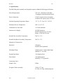
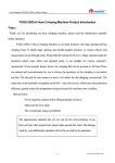
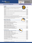
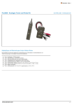
PRO3000
Instruction Manual
Full Extractive Probe Assembly
Part Number 111983-00
8Sep2008
© 2011 Thermo Fisher Scientific Inc. All rights reserved.
Specifications, terms and pricing are subject to change. Not all products are available in all countries. Please
consult your local sales representative for details.
Thermo Fisher Scientific
Air Quality Instruments
27 Forge Parkway
Franklin, MA 02038
1-508-520-0430
www.thermoscientific.com/aqi
WEEE Compliance
This product is required to comply with the European Union’s Waste
Electrical & Electronic Equipment (WEEE) Directive 2002/96/EC. It is
marked with the following symbol:
Thermo Fisher Scientific has contracted with one or more
recycling/disposal companies in each EU Member State, and this product
should be disposed of or recycled through them. Further information on
Thermo Fisher Scientific’s compliance with these Directives, the recyclers
in your country, and information on Thermo Fisher Scientific products
which may assist the detection of substances subject to the RoHS Directive
are available at: www. thermoscientific.com/WEEERoHS.
Thermo Fisher Scientific
WEEE Compliance
Thermo Fisher Scientific
WEEE Compliance
Where to Get Help
Service is available from exclusive distributors worldwide. Contact one of
the phone numbers below for product support and technical information
or visit us on the web at www.thermoscientific.com/aqi.
1-866-282-0430 Toll Free
1-508-520-0430 International
We continue to support our customers with advanced online resources.
Our Air Quality Instruments Online Library allows our customer’s access
to product documents and information on a constant basis.
Available 24-hours a day and seven-days a week, the online library provides
quick access to information regardless of time zone or office hours.
To register for an account or log in, please visit
www.thermoscientific.com/aqilibrary.
Thermo Fisher Scientific
Where to Get Help
PRO3000
TFS
Claims For Damaged Shipments
A.
The Thermo Fisher Scientific (TFS) PRO3000 is shipped ready for
operation. Immediate inspection of the TFS PRO3000 should follow upon receipt.
Inventory of the container should be checked against the enclosed packing list. If
there is a shortage of items, the operator should immediately contact TFS. If the
contents are damaged, the carrier and TFS should be notified immediately.
B.
The following documents are necessary to support claims:
1.
Original freight bill and bill of lading.
2.
Original invoice or photocopy of original invoice.
3.
Copy of the packing list.
4.
Photographs of damaged equipment and container.
NOTICE
Material contained in this manual is proprietary information of TFS. The TFS manual is to be
used only for the installation, operation, and servicing of this product. For further
information or assistance contact:
Thermo Fisher Scientific
All rights reserved. No part of this publication may be reproduced or stored in a retrieval
system or transmitted in any form or by any means, electronic, mechanical photocopying,
recording, or otherwise, without the prior written permission of TFS.
REVISION HISTORY
Revision
Pages Affected
Revision
No.
0
First issue
1
Added heated probe barrel information
Rev 1
September 08, 2008
All
All
Revision Date
May 30, 2008
Sept 8, 2008
ii
PRO3000
TFS
TABLE OF CONTENTS
1.0
PRODUCT DESCRIPTION ................................................................................ 1-1
1.1 Introduction.................................................................................................... 1-1
1.2 Probe Assembly Hardware ............................................................................ 1-1
1.3 Specifications................................................................................................. 1-3
2.0
THEORY OF OPERATION................................................................................ 2-1
2.1 General........................................................................................................... 2-1
2.2 Gas Flow Functional Description .................................................................. 2-1
2.2.1 Sampling Mode............................................................................... 2-1
2.2.2 Purge Mode..................................................................................... 2-2
2.2.3 Calibration Mode ............................................................................ 2-2
3.0
INSTALLATION AND OPERATION ............................................................... 3-1
3.1 Site Location and Preparation........................................................................ 3-1
3.2 Limitations at the Probe Site.......................................................................... 3-1
3.2.1 Stack Temperature Extremes .......................................................... 3-1
3.2.2 Ambient Temperature Extremes ..................................................... 3-2
3.2.3 Process Pressure.............................................................................. 3-2
3.3 General Installation........................................................................................ 3-3
3.3.1 Probe Assembly Enclosure ............................................................. 3-3
3.3.2 Air Supply/ Calibration Gas Line ................................................... 3-4
3.3.3 Sample Line .................................................................................... 3-4
3.3.4 Power .............................................................................................. 3-4
3.3.5 Control and Data Lines ................................................................... 3-4
3.4 Probe Assembly Start-up .............................................................................. 3-4
4.0 MAINTENANCE ...................................................................................................... 4-1
4.1 General........................................................................................................... 4-1
4.2 Required Maintenance Equipment ................................................................ 4-1
4.3 Heated Filter Replacement ............................................................................ 4-1
4.4 Trouble Shooting ........................................................................................... 4-2
4.4.1 Zero Drift - Full System.................................................................. 4-2
4.4.2 Span Drift - Full System ................................................................. 4-2
4.4.3 Low Sample Flow Rate................................................................... 4-2
4.4.4 Low Span Reading.......................................................................... 4-2
4.4.5 High Dew Point/Condensation in Sample Lines ............................ 4-3
5.0 RETURNING ASSEMBLIES FOR REPAIR ........................................................... 5-1
5.1 Obtaining Replacement Parts ........................................................................ 5-1
5.2 Spare Parts List, PRO3000 ............................................................................ 5-1
6.0 APPENDIX................................................................................................................ 6-1
Drawing #
Rev Sheet Description
07040004
0
1 of 1 Filter, Assy, Heated, Extractive, Fiber Filter
07990181
0
1 of 1 Probe, Assy, Heated Barrel, for PRO3000
XXXX-7121-D 0,
1 of 2 Source Extractive Probe Flow Diagram
XXXX-7131-D 0,
1 of 2 Source Extractive Probe Wiring Diagram
XXXX-7151-D 0,
1 of 2 Source Extractive Probe Assembly
XXXX-7151-D 0,
2 of 2 Source Extractive Probe Assembly
Rev 1
September 08, 2008
iii
PRO3000
1.0
TFS
PRODUCT DESCRIPTION
1.1 Introduction
The installation and operation manual provides instruction for basic installation, preventive
maintenance, corrective maintenance, and trouble shooting procedures for the PRO3000 full extractive
probe assembly that was developed to provide a lower cost, more reliable alternative to existing
sampling systems. This manual contains four sections:
Section 1 - Product Description: Hardware description, instrument operating parameters,
and physical characteristics.
Section 2 - Theory of Operation: Complete functional description.
Section 3 - Installation and Operation: Instructions for installation and operation of the
probe assembly.
Section 4 - Maintenance: Routine inspection, trouble shooting, corrective procedures, and
repair/replacement for major assemblies.
1.2 Probe Assembly Hardware
The PRO3000 probe assembly consists of an enclosure containing a probe barrel (optional heated probe
barrel), a heated filter assembly, purge/calibration gas valves and temperature controlling electronics
(see Figure 1.2-1). The PRO3000 is attached to the stack by a four-inch pipe flange, or may be fitted
with a 2.5, 3 or 6-inch flange to suit existing sampling ports. The probe barrel is inserted into the stack
through an opening in the back of the assembly enclosure.
Figure 1.2-1 PRO3000 Probe Box
Rev 1
September 08, 2008
1-1
PRO3000
TFS
The probe assembly consists of a stainless steel probe barrel and a heated filter assembly shown in
Figure 1.2-2. A heated, high capacity, sub-micron filter is housed in a stainless steel filter body that is
located within the heated filter assembly, and can be easily replaced during preventive maintenance.
The sampling probe barrel is typically a section of heavy wall tubing with an outer diameter of 5/8
inches and an inner diameter of .425 inches. Material for the probe barrel is selected for compatibility
with the process stream and is most frequently supplied in 316 stainless steel.
The sample probe is housed in a fiberglass enclosure that measures approximately 20 inches (H) by 20
inches (W) by 10 inches (D). The enclosure is designed to protect instruments and electrical controls
from highly corrosive atmospheres. Enclosure material other than the standard fiberglass may be
selected to suit special ambient conditions at the sampling point.
HEATED FILTER ASSEMBLY
PROBE BARREL
SAMPLE/PURGE
CAL GAS
Figure 1.2-2 PRO3000 Heated Probe Assembly
Rev 1
September 08, 2008
1-2
PRO3000
TFS
1.3 Specifications
The PRO3000 probe assembly was designed to operate within the following specifications.
Power Requirements:
120 VAC, 300 Watts (1300 Watts
if equipped with heated probe barrel)
Power Connection:
CSA/UL Approved screw terminal.
Terminal wire capacity up to 10 AWG.
Ambient Operating Temperature Range:
-25° C (-13° F) to 50° C (122° F)
Maximum Process Temperature:
600° C (1112° F)
Calibration Gas Flow Rate:
5.0 L/min minimum
Instrument Air Supply:
60 PSIG minimum
80 PSIG maximum via 1/2 inch
tubing - 0.300 inch I.D. min.
Heated Filter Assembly Temperature:
300° F ± 5° F
Heated Probe Barrel Assembly Temperature:
300° F ± 5° F
Materials of Construction:
Enclosure:
Fiberglass
Stainless Steel (optional)
Mounting Flange:
Stainless Steel, 4 inch standard pipe
Optional: 2.5 to 6 inch
Heated Filter Body:
316 Stainless Steel
Probe Barrel:
316 Stainless Steel
Hastelloy C-276 (optional)
Connecting Lines/
Sample Lines:
Weight of Probe Assembly:
Rev 1
Teflon
39 lbs. (17.7 kg)
52.5 lbs. (23.8 kg) with heated probe
September 08, 2008
1-3
PRO3000
2.0
TFS
THEORY OF OPERATION
2.1 General
The PRO3000 full extractive probe assembly is used to extract and condition a continuous
sample from a stack or duct for transport to a gas analysis system.
2.2 Gas Flow Functional Description
Operation of the probe assembly consists of three modes: Sampling, Purge, and Calibration
Modes.
2.2.1 Sampling Mode
Process gas enters the sampling system at the probe barrel tip. The process gas moves down the
probe barrel at a flow rate of 2.5-5 L/min. From the sampling probe, the gas enters the probe
enclosure and flows into the heated filter, shown in cross section in Figure 2.2.1-1.
The filter element is temperature controlled at 300° F ± 5° F by a band heater element and an
external electronic temperature controller. The filter element is selected for its inertness to the
process gas and is a borosilicate glass fiber element having collection efficiency rating of 0.1
micron. The filter element may be removed by removing the filter cap. A port is provided to
introduce purge air and calibration gas. The heated filter body is fabricated from 316 stainless
steel to minimize sample contamination due to unwanted reactions with the process gas.
After passing through the heated filter element, the filtered process gas flows through a heat
traced umbilical which is maintained at 300°F ±5° F.
Process gas is pulled through the heated filter and the heated Teflon® sample line by a sample
transport pump located in sample chiller assembly in the remote analysis system. From the
sample line, the process gas flows through a sample chiller, an orifice protection filter, through a
flow control orifice and then through the sample transport pump to the bypass vent. This bypass
vent flow is used to establish a reasonable transport time (usually less than 20 seconds). The
bypass flow can be used by other gas analyzers attached to the bypass vent. The flow control
orifice is selected to obtain a desired flow rate to the remote analyzer. This sample is then
drawn to a gas analyzer via an internal pump in order to generate an electrical signal
proportional to the specific gas being analyzed. From the remote analyzer, the diluted process
gas flows to a vent manifold.
2.2.2 Purge Mode
The probe is cleaned periodically by introducing high-pressure purge air from the purge air
solenoid valve (SV1 & SV2) into the filter body and exiting into the process through the sample
probe. The analysis system controller operates the purge solenoid valve automatically. A
manual purge may be initiated from the controller at any time but the preferred method is to
automatically energize the purge/cal gas solenoid valve. Purge frequencies may vary from every
15 minutes for applications with extremely heavy particulate concentrations to several hours for
cleaner applications. The purge pulse lasts approximately 10 seconds. Longer purge times
Rev 1
September 08, 2008
2-1
PRO3000
TFS
could result in heated filter cooling.
2.2.3 Calibration Mode
The PRO3000 probe assembly is calibrated by passing a gas of known concentration through all
the components in the sample analysis system and adjusting the response of the gas analysis
system to equal the value of the known calibration gas. Calibrating in this manner allows for
compensation of the total system for losses in filter elements or other pneumatic components,
and in process gas flow rates. A typical calibration gas flow path is as follows:
From the calibration cylinder, the calibration gas flows from a flow controlling device and
calibration gas valve located in the valve/ switch chassis, through the calibration gas line to the
cal gas check valve and then to the cal gas inlet in the tee fitting which supports the heated filter
assembly. The gas enters the filter body through the calibration gas inlet. The remote
calibration gas solenoid valve allows the flow of calibration gas to be initiated remotely through
a controller in the remote analysis system. From the inlet tee fitting, the calibration gas passes
through all system components at the same flow rates and conditions as the process sample gas.
Rev 1
September 08, 2008
2-2
PRO3000
TFS
3.0 INSTALLATION AND OPERATION
3.1 Site Location and Preparation
The 40 CFR Performance Specification Two (2) provides a guide to proper site selection and
lists several points that should be considered for most applications. The most accurate readings
will usually be obtained when the guidelines of Performance Specification Two (2) are followed.
The PRO3000 extractive probe conditioning assembly is installed on a four (4) inch pipe flange.
The pipe flange must be installed on a pipe nipple extending six (6) inches from the outer wall
of the stack. The pipe nipple is used to allow clearance behind the conditioning assembly for
installation of the four (4) 1/2-inch X 1 3/4-inch stainless steel mounting bolts. Also allow a
clear space, at least the width of the probe enclosure, in front of the enclosure door to allow the
door to be opened. The four (4) inch pipe flange must be aligned as shown in Figure 3.1-1. A
slip-type pipe flange is recommended to insure that the conditioning assembly can be leveled.
The extractive probe assembly should be installed in a location that will allow maintenance
personnel access to the front of the enclosure. All maintenance can be performed from the front
of the unit.
3.2 Limitations at the Probe Site
The placement of the PRO3000 probe assembly is important to achieve its maximum reliability.
3.2.1 Stack Temperature Extremes
The PRO3000 probe barrel may be supplied using several different materials. Specific
limitations for each probe barrel type must be considered separately.
A) 316 stainless steel probe barrel
A 316 stainless steel probe barrel is used at temperatures up to 1200° F with lengths up
to six (6) feet. Additional lengths can be use with the optional probe barrel support.
B) Hastelloy C-276 Probe Barrel:
A Hastelloy C-276 probe barrel may be used in installations that require abrasion
resistant material for the probe with lengths up to six (6) feet. Additional lengths can be
use with the optional probe barrel support. It is best to use the shortest possible probe
barrel length for response times and consistent with good sampling practice.
Rev 1
September 08, 2008
3-1
PRO3000
TFS
22.5°
90
.0°
(NOTE-1)
52"
48"
(NOTE-4)
(NOTE-3)
7"
(NOTE-5 & 6)
(NOTE-2)
5°
1
4
1
4
VIEW 'A'-'A'
FLANGE WELDED TO PIPE SPOOL
IN THIS CONFIGURATION
UNLINED PROBE
EXTENDING INTO STACK
5/8" TUBE 316 SS
(NOTE-4)
MAINTENANCE
CLEARANCE
(NOTE-7, 8, 9)
(DETAIL-A)
10.32
1. DO NOT ALLOW BURRS ON INSIDE DIAMETER OF
4" SCHEDULE 40 PIPE (SUPPLIED BY CUSTOMER)
2. WELD PIPE TO STACK USING 1/4" FILLET WELD
3. (A) - USE THESE FOUR HOLES FOR PROBE INSTALLATION
4. PROBE LENGTH WILL MEET US EPA 1 METER PENETRATION
REQUIREMENT; MAY BE SHORTENED, IF NECESSARY,
TO PLACE PROBE TIP AT CENTER OF GAS STREAM
48" (MINIMUM)
72" (MAXIMUM)
STACK WALL
NOTES:
5. ALLOW 7" CLEARANCE BETWEEN FLANGE AND WALL
OR FLANGE AND INSULATION
CATWALK OR FLOOR
6. CUSTOMER IS TO ENSURE THE STRUCTURAL INTEGRITY
OF THE STACK OR DUCT AT ALL PENETRATIONS
7. ALLOW 16" CLEARANCE FOR DOOR OPENING
8. ALLOW CLEARANCE IN FRONT OF PROBE
BOX FOR PROBE REMOVAL
48"
(RECOMMENDED MINIMUM)
9. CLEARANCE FOR MAINTENANCE
Figure 3.1-1 PRO3000 Probe Box Installation
3.2.2 Ambient Temperature Extremes
The PRO3000 probe assembly may be operated at a maximum ambient temperature of 50° C
(140° F). Optimum operation of the sampling system will always be achieved if a sampling
location is selected with moderate temperatures.
3.2.3 Process Pressure
The sampling system should not be installed in sampling locations that have pressures which
exceed ± 30 inches H2O. Positive pressure ducts are a special problem in that the maintenance is
complicated by process gases escaping into the area of the maintenance personnel when the filter
body is opened for maintenance. Positive pressure stacks or ducts may be easily sampled if a
small portion of the stream can be vented to atmosphere and the probe is then allowed to sample
this atmospheric vent. The probe typically extracts between 2.5 and 5.0 L/min.
Rev 1
September 08, 2008
3-2
PRO3000
TFS
3.3 General Installation
3.3.1 Probe Assembly Enclosure
The probe assembly is shipped in two separate containers. The probe enclosure is installed first
and then the probe is installed through an opening in the back of the enclosure into the stack. To
install the probe assembly, perform the steps as outlined in the following three sections.
Probe Enclosure Installation
Install the enclosure on the four (4) inch flange using a proper flange gasket and four 1/2 inch X
1 3/4 inch stainless steel bolts, (See Figure 3.3.1-2).
22.5°
FULL FACE
FLANGE GASKET
(SUPPLIED BY CUSTOMER)
'A'
4" SCH 40 PIPE
(NOTE-6)
PROBE
BOX
(NOTE-1)
90
.0°
1/2"-13 UNC SS NUT,
LOCK AND FLAT WASHER.
(SUPPLIED BY VENDOR)
(NOTE-2)
4" 150# RF FLANGE
(SUPPLIED BY CUSTOMER)
'A'
VIEW 'A'-'A'
NOTES:
1. DO NOT ALLOW BURRS ON INSIDE DIAMETER OF
4" SCHEDULE 40 PIPE (SUPPLIED BY CUSTOMER)
FLANGE WELDED TO PIPE SPOOL
IN THIS CONFIGURATION
2. (A) - USE THESE FOUR HOLES FOR PROBE INSTALLATION
Figure 3.3.1-2 Customer Pipe Spool Installation
A) Inspect the probe barrel assembly for proper flange spacing and orientation (factory set),
Figure 3.3.1-2.
B) Install the probe flange gasket (factory supplied) over the process end of the probe barrel to
be used to seal process gases from the enclosure.
C) Insert the probe barrel assembly through the flange porthole in the back of the enclosure with
the bend downward. Align the three-hole probe-mounting flange and flange gasket to the threehole pattern of the enclosure flange porthole.
D) Insert the three (3) supplied 1/4-20 X 1-3/4 inch bolts through the probe mounting flange
into the threaded holes, and tighten.
E) If equipped with a heated probe barrel, connect the probe barrel heater leads and the probe
barrel RTD leads to the terminal strip in the lower compartment.
Rev 1
September 08, 2008
3-3
PRO3000
TFS
Probe Head Installation
A) Connect the sample/purge tube.
B) Connect the calibration tube.
C) Connect the probe filter heater band heater to the terminal strip in the lower compartment.
Verify that the band heater is tightly clamped to the heated filter body.
D) Insert the temperature controller RTD into the hole provided, install the retaining screw and
connect the leads to the terminal strip in the lower compartment.
Check all connections.
3.3.2 Calibration Gas Line
Connect the Teflon® calibration gas line to the appropriate 3/8" inch stainless steel compression
tube fitting located on the right side of support plate in the enclosure.
3.3.3 Air Supply/Sample Line
Connect the Teflon® sample line and purge air line to the appropriate 3/8-inch compression type
tube fittings located on the left side of support plate in the enclosure. The maximum length for
the sample and calibration lines varies with individual applications. (Refer to the specific
installation drawings for each application.)
3.3.4 Control and Signal Lines
The control and signal lines are part of the tubing/wiring umbilical. Connect the control lines
and signal lines using specified shielded cable for the heated filter temperature control and
signal. (Refer to specific installation drawings for each application.)
3.4 Probe Assembly Start-up
The probe assembly may be started up as follows:
A) Locate the probe head temperature controller, located in the probe controller CTL3000 in the
rack. Confirm that the proper parameters are entered into the temperature controllers (Refer to
the CTL3000 series probe controller manual).
B) Verify that the band heater is tightly clamped to the heated filter body.
C) Turn on the controller AC power switch at the rack.
D) Insert a thermocouple temperature probe in one of the test port located above the RTD port
in the heated filter body and allow the temperature to stabilize. This temperature should be 300°
Rev 1
September 08, 2008
3-4
PRO3000
TFS
F.
E) Increase or decrease the temperature adjustment of the CTL3000 heated filter temperature
controller to obtain a probe head temperature of 300° F ± 5° F. Allow temperature to stabilize to
confirm that the heater circuitry is controlling properly. The temperature of the heated filter may
be adjusted as required. (If equipped with a heated probe barrel, perform the same adjustment
on the heated probe barrel temperature controller.)
F) Turn on the main air supply from the air clean-up assembly (if supplied) and adjust the air
supply to 60PSI.
G) Initiate a purge cycle on the probe assembly from the system controller.
The PRO3000 probe assembly is now ready to be calibrated with the complete monitoring
system.
Rev 1
September 08, 2008
3-5
PRO3000
4.0
TFS
MAINTENANCE
4.1 General
The following procedures are designed to allow the maintenance technician to accomplish all necessary
maintenance procedures on the PRO3000 probe assembly.
4.2 Required Maintenance Equipment
To perform maintenance on the sample system, the following equipment is required.
A.
Normal hand tools
4.3 Heated Filter Replacement
NOTE: The existing heated filter must be replaced with a new one each time the filter cap is
removed, (the filter is slightly crushed to seal). Once a crushed filter is removed, it will not seal
properly and can not be used again.
CAUTION: THE STAINLESS STEEL FILTER BODY OPERATES AT 300° F AND CAN
CAUSE SEVERE BURNS. USE EXTREME CARE WHEN WORKING IN THE UPPER
SECTION OF THE PROBE ENCLOSURE.
A) Remove the heated filter cap.
B) Remove the filter from the mandrill of the heated filter cap.
C) Inspect the filter body and cap for particulate accumulation around the filter seats. Clean the
filter body and seat by wiping with a soft cloth.
D) Install a new filter element onto the cap mandrill, then insert the cap and filter into the filter
body. Tighten the filter cap until it contacts the filter body.
4.4Trouble Shooting
4.4.1 Zero Drift - Full System
Zero drift is independent of the dilution system, as any dilution of a zero gas will still
cause a zero indication on the analyzer. Check the analyzer location for large
temperature changes or other changes in the analyzer utilities. Please see the system
manual for zero drift calculations.
4.4.2 Span Drift - Full System
Span drift may be caused by many different variables throughout the monitoring system.
Most problems with the sampling system will be indicated by a failure to pass the daily
span calibration. Failure to pass the daily calibration is subdivided into several different
Rev 1
September 08, 2008
4-1
PRO3000
TFS
problem areas that would cause a high or low indication on daily calibration. For each
possible problem, a corrective action is listed. Please see the system manual for span
drift calculations.
4.4.3 Low Sample Flow Rate
Possible Problem - Leak between filter body and probe barrel, sample outlet or purge
inlet.
Corrective Action: Remove the probe barrel/heated filter assembly, plug the probe
barrel and sample outlet and pressurize to 30 psi. Check for a leak at the probe barrel,
sample outlet fitting or cal gas inlet. If a leak is detected, tighten the fitting and repeat
the leak check.
Possible Problem - Leak around filter cap.
Corrective Action: Replace cap o-ring.
4.4.4 Low Span Reading
Possible Problem - Dirty Main Filter element.
Corrective Action: Replace filter element.
Possible Problem - Leak at filter body cap.
Corrective Action: Replace filter cap o-ring. Replace filter.
Possible Problem - Leak at sample and cal gas valve connections.
Corrective Action: Check for leaks. Tighten connections as required.
Possible Problem - Leaky purge/cal gas valve.
Corrective Action: Replace valve.
4.4.5 High Dew Point/Condensation in Sample Lines
Possible Problem - Failure of filter heaters or solid state relay.
Corrective Action: Check heater and heater solid state relay. Replace if defective.
Rev 1
September 08, 2008
4-2
PRO3000
TFS
5.0 Returning Assemblies for Repair
Should it become necessary to return any assembly, sub-assembly, or component for repair or
replacement, contact the factory prior to shipment for specific information such as return
authorization number, shipping instructions, price, time to repair, etc. Also include pertinent
facts describing the nature of the problem. Ship all components to the following:
Thermo Fisher Scientific
5.1 Obtaining Replacement Parts The following information must be included in all purchase
orders for parts:
A. TFS Model and S/N of major assembly
B. Part Number (found in parts tables)
C. Description of part
5.2 Spare Parts List, PRO3000
Part Number
Description
Recommended Quantity
25503012
O-ring, filter body
2*
26002018
Filter, 0.1 Micron, STD
4*
45510062
Valve, 2 way NC 120V
1/4NPT-3/16 orifice
1*
53010098
Heater band, 300 Watt, 1.5”
wide, 120 VAC
2*
53040025
RTD, .25” x 1.5”
HEATER, ROD, 95",
120VAC, 1000W
1*
53040051**
1*
1*
RTD, PROBE, 24" 316
SHEATH, 12" FG
* THESE PARTS ARE RECOMMENDED AS A MINIMUM FROM THE TFS SERVICE
DEPARTMENT TO AID IN ACQUIRING 98 % UP TIME.
53040128**
**THESE PARTS USED IN THE HEATED PROBE ONLY.
Teflon® is a registered trademark of E. I. duPont de Nemours & Company, Inc.
Gore-tex® is a registered trademark of W. L. Gore & Associates, Inc
Rev 1
September 08, 2008
5-1
PRO3000
TFS
6.0 APPENDIX A
Drawing #
Rev
07040004
0
1 of 1
Filter, Assy, Heated, Extractive, Fiber Filter
07990181
0
1 of 1
Probe, Assy, Heated Barrel, for PRO3000
XXXX7121
0,
1 of 1
Source Extractive Probe Flow Diagram
XXXX7131
0,
1 of 1
Source Extractive Probe Wiring Diagram
XXXX7151
0,
1 of 2
Source Extractive Probe Assembly
XXXX7151
0,
2 of 2
Source Extractive Probe Assembly
Rev 1
Sheet
Description
September 08, 2008
6-1
Warranty
Warranty
Seller warrants that the Products will operate or perform substantially in
conformance with Seller's published specifications and be free from defects
in material and workmanship, when subjected to normal, proper and
intended usage by properly trained personnel, for the period of time set
forth in the product documentation, published specifications or package
inserts. If a period of time is not specified in Seller’s product
documentation, published specifications or package inserts, the warranty
period shall be one (1) year from the date of shipment to Buyer for
equipment and ninety (90) days for all other products (the "Warranty
Period"). Seller agrees during the Warranty Period, to repair or replace, at
Seller's option, defective Products so as to cause the same to operate in
substantial conformance with said published specifications; provided that
(a) Buyer shall promptly notify Seller in writing upon the discovery of any
defect, which notice shall include the product model and serial number (if
applicable) and details of the warranty claim; (b) after Seller’s review, Seller
will provide Buyer with service data and/or a Return Material
Authorization (“RMA”), which may include biohazard decontamination
procedures and other product-specific handling instructions; and (c) then,
if applicable, Buyer may return the defective Products to Seller with all
costs prepaid by Buyer. Replacement parts may be new or refurbished, at
the election of Seller. All replaced parts shall become the property of Seller.
Shipment to Buyer of repaired or replacement Products shall be made in
accordance with the Delivery provisions of the Seller’s Terms and
Conditions of Sale. Consumables, including but not limited to lamps,
fuses, batteries, bulbs and other such expendable items, are expressly
excluded from the warranty under this warranty.
Notwithstanding the foregoing, Products supplied by Seller that are
obtained by Seller from an original manufacturer or third party supplier are
not warranted by Seller, but Seller agrees to assign to Buyer any warranty
rights in such Product that Seller may have from the original manufacturer
or third party supplier, to the extent such assignment is allowed by such
original manufacturer or third party supplier.
In no event shall Seller have any obligation to make repairs, replacements
or corrections required, in whole or in part, as the result of (i) normal wear
and tear, (ii) accident, disaster or event of force majeure, (iii) misuse, fault
or negligence of or by Buyer, (iv) use of the Products in a manner for which
Thermo Fisher Scientific
Warranty
they were not designed, (v) causes external to the Products such as, but not
limited to, power failure or electrical power surges, (vi) improper storage
and handling of the Products or (vii) use of the Products in combination
with equipment or software not supplied by Seller. If Seller determines
that Products for which Buyer has requested warranty services are not
covered by the warranty hereunder, Buyer shall pay or reimburse Seller for
all costs of investigating and responding to such request at Seller's then
prevailing time and materials rates. If Seller provides repair services or
replacement parts that are not covered by the warranty provided in this
warranty, Buyer shall pay Seller therefor at Seller's then prevailing time and
materials rates. ANY INSTALLATION, MAINTENANCE, REPAIR,
SERVICE, RELOCATION OR ALTERATION TO OR OF, OR
OTHER TAMPERING WITH, THE PRODUCTS PERFORMED BY
ANY PERSON OR ENTITY OTHER THAN SELLER WITHOUT
SELLER'S PRIOR WRITTEN APPROVAL, OR ANY USE OF
REPLACEMENT PARTS NOT SUPPLIED BY SELLER, SHALL
IMMEDIATELY VOID AND CANCEL ALL WARRANTIES WITH
RESPECT TO THE AFFECTED PRODUCTS.
THE OBLIGATIONS CREATED BY THIS WARRANTY
STATEMENT TO REPAIR OR REPLACE A DEFECTIVE PRODUCT
SHALL BE THE SOLE REMEDY OF BUYER IN THE EVENT OF A
DEFECTIVE PRODUCT. EXCEPT AS EXPRESSLY PROVIDED IN
THIS WARRANTY STATEMENT, SELLER DISCLAIMS ALL
OTHER WARRANTIES, WHETHER EXPRESS OR IMPLIED, ORAL
OR WRITTEN, WITH RESPECT TO THE PRODUCTS,
INCLUDING WITHOUT LIMITATION ALL IMPLIED
WARRANTIES OF MERCHANTABILITY OR FITNESS FOR ANY
PARTICULAR PURPOSE. SELLER DOES NOT WARRANT THAT
THE PRODUCTS ARE ERROR-FREE OR WILL ACCOMPLISH
ANY PARTICULAR RESULT.
Warranty
Thermo Fisher Scientific