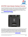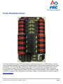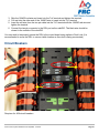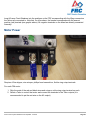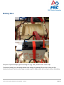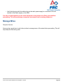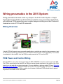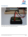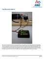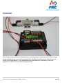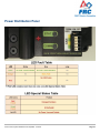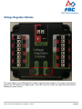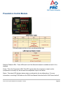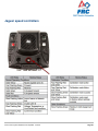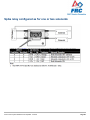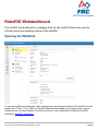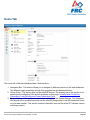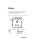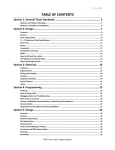
1
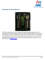
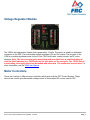
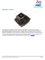
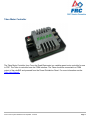
2015 CONTROL SYSTEM
HARDWARE
2015 Control System Hardware
Table of Contents
General Hardware .............................................................................. 3
2015 FRC Control System Hardware Overview ...................................................... 4
Wiring the 2015 FRC Control System.................................................................... 20
Wiring CAN Jaguars in the 2015 System .............................................................. 47
Updating CAN Jaguar Firmware ............................................................................ 51
Wiring pneumatics in the 2015 System ................................................................. 56
Updating and Configuring Pneumatics Control Module and Power Distribution
Panel...................................................................................................................... 61
Status Light Quick Reference ................................................................................ 76
RoboRIO .......................................................................................... 90
RoboRIO Webdashboard....................................................................................... 91
RoboRIO FTP ...................................................................................................... 101
RoboRIO User Accounts and SSH ...................................................................... 103
RoboRIO Brownout and Understanding Current Draw ........................................ 106
2015 Control System Hardware
General Hardware
2015 Control System Hardware Last Updated: 1/1/2015
Page 3
2015 Control System Hardware
2015 FRC Control System Hardware Overview
The goal of this document is to provide a brief overview of the hardware components that
make up the 2015 FRC Control System. Each component will contain a brief description
of the component function, a brief listing of critical connections, and a link to more
documentation if available. Note that for complete wiring instructions/diagrams, please
see the Wiring the 2015 Control System document.
National Instruments roboRIO
The NI-roboRIO is the main robot controller used for FRC 2015. The roboRIO includes a dual-core ARM
Cortex™-A9 processor and FPGA which runs both trusted elements for control and safety as well as
team-generated code. Integrated controller I/O includes a variety of communication protocols (Ethernet,
USB, CAN, SPI, I2C, and serial) as well as PWM, servo, digital I/O, and analog I/O channels used to
connect to robot peripherals for sensing and control.The roboRIO should connect to the dedicated 12V
port on the Power Distribution Panel for power. Wired communication is available via USB or Ethernet.
Detailed information on the roboRIO can be found in the roboRIO User Manual.
2015 Control System Hardware Last Updated: 1/1/2015
Page 4
2015 Control System Hardware
Power Distribution Panel
The Power Distribution Panel (PDP) is designed to distribute power from a 12VDC battery to various
robot components through auto-resetting circuit breakers and a small number of special function fused
connections. The PDP provides 8 output pairs rated for 40A continuous current and 8 pairs rated for
30A continuous current. The PDP provides dedicated 12V connectors for the roboRIO, as well as
connectors for the Voltage Regulator Module and Pneumatics Control Module. It also includes a CAN
interface for logging current, temperature, and battery voltage. For more detailed information, see the
PDP User Manual.
2015 Control System Hardware Last Updated: 1/1/2015
Page 5
2015 Control System Hardware
Pneumatics Control Module
The PCM is a device that contains all of the inputs and outputs required to operate 12V or 24V
pneumatic solenoids and the on board compressor. The PCM is enabled/disabled by the roboRIO over
the CAN interface. The PCM contains an input for the pressure sensor and will control the compressor
automatically when the robot is enabled and a solenoid has been created in the code. The device also
collects diagnostic information such as solenoid states, pressure switch state, and compressor state.
The module includes diagnostic LED’s for both CAN and the individual solenoid channels. For more
information see the PCM User Manual.
2015 Control System Hardware Last Updated: 1/1/2015
Page 6
2015 Control System Hardware
Voltage Regulator Module
The VRM is an independent module that is powered by 12 volts. The device is wired to a dedicated
connector on the PDP. The module has multiple regulated 12V and 5V outputs. The purpose of the
VRM is to provide regulated power for the D-Link 1522 RevB radio, custom circuits, and IP vision
cameras. Note: The two connector pairs associated with each label have a combined rating of
what the label indicates (e.g. 5V/500mA total for both pairs not for each pair). The 12V/2A limit is
a peak rating, the supply should not be loaded with more than 1.5A continuous current draw. For
more information, see the VRM User Manual.
Motor Controllers
There are a variety of different motor controllers which work with the FRC Control System. These
devices are used to provide variable voltage control of the brushed DC motors used in FRC.
2015 Control System Hardware Last Updated: 1/1/2015
Page 7
2015 Control System Hardware
Jaguar Motor Controller
The Jaguar Motor Controller from VEX Robotics (formerly made by Luminary Micro and Texas
Instruments) is a variable speed motor controller for use in FRC. The Jaguar can be controlled using
either the PWM interface or over the CAN bus. The Black Jaguar can also be used to convert from
RS232 (from the BDC-Comm PC program) to the CAN bus. The Jaguar should be connected using one
of these control interfaces and powered from the Power Distribution Panel. For more information, see
the Jaguar Getting Started Guide, Jaguar Datasheet and Jaguar FAQ on this page.
2015 Control System Hardware Last Updated: 1/1/2015
Page 8
2015 Control System Hardware
Talon Motor Controller
The Talon Motor Controller from Cross the Road Electronics is a variable speed motor controller for use
in FRC. The Talon is controlled over the PWM interface. The Talon should be connected to a PWM
output of the roboRIO and powered from the Power Distribution Panel. For more information see the
Talon User Manual.
2015 Control System Hardware Last Updated: 1/1/2015
Page 9
2015 Control System Hardware
Talon SRX
The Talon SRX motor controller is a CAN-enabled "smart motor controller" from Cross The Road
Electronics/VEX Robotics. The Talon SRX has an electrically isolated metal housing for heat
dissipation, making the use of a fan optional. The Talon SRX can be controlled over the CAN bus or
PWM interface. When using the CAN bus control, this device can take inputs from limit switches and
potentiometers, encoders, or similar sensors in order to perform advanced control such as limiting or
PID(F) closed loop control on the device. For more information see the Talon SRX User Manual.
2015 Control System Hardware Last Updated: 1/1/2015
Page 10
2015 Control System Hardware
Victor 888 Motor Controller / Victor 884 Motor Controller
The Victor 888 Motor Controller from VEX Robotics is a variable speed motor controller for use in FRC.
The Victor 888 replaces the Victor 884, which is also usable in FRC. The Victor is controlled over the
PWM interface. The Victor should be connected to a PWM output of the roboRIO and powered from the
Power Distribution Panel. For more information, see the Victor 884 User Manual and Victor 888 User
Manual.
2015 Control System Hardware Last Updated: 1/1/2015
Page 11
2015 Control System Hardware
Victor SP
The Victor SP motor controller is a PWM motor controller from Cross The Road Electronics/VEX
Robotics. The Victor SP has an electrically isolated metal housing for heat dissipation, making the use
of the fan optional. The case is sealed to prevent debris from entering the controller. The controller is
approximately half the size of previous models. For more information, see the Victor SP User Manual.
2015 Control System Hardware Last Updated: 1/1/2015
Page 12
2015 Control System Hardware
Spike H-Bridge Relay
The Spike H-Bridge Relay from VEX Robotics is a device used for controlling power to motors or other
custom robot electronics. When connected to a motor, the Spike provides On/Off control in both the
forward and reverse directions. The Spike outputs are independently controlled so it can also be used to
provide power to up to 2 custom electronic circuits. The Spike H-Bridge Relay should be connected to a
relay output of the roboRIO and powered from the Power Distribution Panel. For more information, see
the Spike User's Guide.
2015 Control System Hardware Last Updated: 1/1/2015
Page 13
2015 Control System Hardware
Axis M1013/M1011/206 Ethernet Camera
The Axis M1013, M1011 and Axis 206 Ethernet cameras are used for capturing images for vision
processing and/or sending video back to the Driver Station laptop. The camera should be wired to a 5V
power output on the Voltage Regulator Module and either the D-Link 1522 RevB (if used on the robot)
or the ethernet port of the roboRIO. For more information, see Configuring an Axis Camera and the Axis
206, Axis M1011, Axis M1013 pages.
2015 Control System Hardware Last Updated: 1/1/2015
Page 14
2015 Control System Hardware
Microsoft Lifecam HD3000
The Microsoft Lifecam HD3000 is a USB webcam that can be plugged directly into the roboRIO. The
camera is capable of capturing up to 1280x720 video at 30 FPS. For more information about the
camera, see the Microsoft product page. For more information about using the camera with the
roboRIO, see the Vision Processing section if this documentation.
2015 Control System Hardware Last Updated: 1/1/2015
Page 15
2015 Control System Hardware
D-Link DAP-1522 Rev B
The D-Link DAP-1522 Rev B robot radio is used to provide wireless communication functionality to the
robot. The device can be configured as an Access Point for direct connection of a laptop for use at
home. It can also be configured as a bridge for use on the field. The robot radio should be powered by
one of the 5V outputs on the VRM and connected to the roboRIO controller over Ethernet. For more
information, see Programming your radio for home use and the D-Link DAP1522 Support Page.
2015 Control System Hardware Last Updated: 1/1/2015
Page 16
2015 Control System Hardware
120A Circuit Breaker
The 120A Main Circuit Breaker serves two roles on the robot: the main robot power switch and a
protection device for downstream robot wiring and components. The 120A circuit breaker is wired to the
positive terminals of the robot battery and Power Distribution boards. For more information, please see
the Cooper Bussmann 18X Series Datasheet (PN: 185120F)
2015 Control System Hardware Last Updated: 1/1/2015
Page 17
2015 Control System Hardware
Snap Action Circuit Breakers
The Snap Action circuit breakers, MX5-A40 and VB3 series, are used with the Power Distribution Panel
to limit current to branch circuits. The MX5-A40 40A MAXI style circuit breaker is used with the larger
channels on the Power Distribution Panel to power loads which draw current up to 40A continuous. The
VB3 series are used with the smaller channels on the PDP to power circuits drawing current of 30A or
less continuous. For more information, see the Datasheeets for the MX5 series and VB3 Series.
2015 Control System Hardware Last Updated: 1/1/2015
Page 18
2015 Control System Hardware
Robot Battery
The power supply for an FRC robot is a single 12V 18Ah battery. The batteries used for FRC are sealed
lead acid batteries capable of meeting the high current demands of an FRC robot. For more information,
see the Datasheets for the MK ES17-12 and Enersys NP18-12. Note that other battery part numbers
may be legal, consult the 2015 FRC Manual for a complete list.
Image credits
Image of roboRIO courtesy of National Instruments. Images of Jaguar Motor Controller, Talon SRX,
Victor 888 Motor Controller, Victor SP Motor Controller, and Spike H-Bridge Relay courtesy of VEX
Robotics, Inc. Lifecam, PDP, PCM, and VRM photos courtesy of FIRST. All other photos courtesy of
AndyMark Inc.
2015 Control System Hardware Last Updated: 1/1/2015
Page 19
2015 Control System Hardware
Wiring the 2015 FRC Control System
This document details the wiring of a basic electronics board for bench-top testing.
The images shown in this section reflect the setup for a Robot Control System using a
roboRIO and Talon SR motor controllers. The setup is similar for Jaguars, Talon SRXs,
Victor 884/888s, or Victor SPs.
Gather Materials
Locate the following control system components and tools
• Kit Materials:
◦ Power Distribution Panel (PDP)
◦ roboRIO
◦ Pneumatics Control Module (PCM)
2015 Control System Hardware Last Updated: 1/1/2015
Page 20
2015 Control System Hardware
◦
◦
◦
◦
◦
◦
◦
◦
◦
◦
◦
◦
◦
◦
◦
◦
◦
◦
◦
◦
Voltage Regulator Module (VRM)
DAP1522 Radio (with power supply and Ethernet cable)
Robot Signal Light (RSL)
2x Talon SR speed controllers
2x PWM cables
2x PWM y-cables
120A Circuit breaker
4x 40A Circuit breaker
6 AWG Red wire
10 AWG Red/Black wire
18 AWG Red/Black wire
22AWG yellow/green twisted CAN cable
2x Andersen SB50 battery connectors
6AWG Terminal lugs
16x Yellow ring terminals (from bag of assorted crimp terminals)
12V Battery
Red/Black Electrical tape
Dual Lock material or fasteners
Zip ties
1/4" or 1/2" plywood
• Tools Required:
◦ Wago Tool or small flat-head screwdriver
◦ Very small flat head screwdriver (eyeglass repair size)
◦ Philips head screw driver
◦ 5mm Hex key (3/16" may work if metric is unavailable)
◦ 1/16" Hex key
◦ Wire cutters, strippers, and crimpers
◦ 7/16” box end wrench or nut driver
Create the Base for the Control System
For a benchtop test board, cut piece of 1/4” or 1/2" material (wood or plastic) approximately 24" x 16".
For a Robot Quick Build control board see the supporting documentation for the proper size board for
the chosen chassis configuration.
2015 Control System Hardware Last Updated: 1/1/2015
Page 21
2015 Control System Hardware
Layout the Core Control System Components
Layout the components on the board. One layout that should work is shown in the images above.
2015 Control System Hardware Last Updated: 1/1/2015
Page 22
2015 Control System Hardware
Fasten components
Using the Dual Lock or hardware, fasten all components to the board. The image shows an example of
possible Dual Lock placement.
2015 Control System Hardware Last Updated: 1/1/2015
Page 23
2015 Control System Hardware
Attach Battery Connector to PDP
Requires: Battery Connector, 6AWG terminal lugs, 1/16" Allen, 5mm Allen, 7/16" Box end
1. Attach terminal lugs to battery connector.
2. Using a 1/16" Allen wrench, remove the two screws securing the PDP terminal cover.
3. Using a 5mm Allen wrench (3/16" will work if metric is not available), remove the negative (-) bolt
and washer from the PDP and fasten the negative terminal of the battery connector.
4. Using a 7/16" box end wrench, remove the nut on the "Batt" side of the main breaker and secure
the positive terminal of the battery conenctor
2015 Control System Hardware Last Updated: 1/1/2015
Page 24
2015 Control System Hardware
Wire Breaker to PDP
Requires: 6AWG red wire, 2x 6AWG terminal lugs, 5mm Allen, 7/16" box end
Secure one terminal lug to the end of the 6AWG red wire. Using the 7/16" box end, remove the nut from
the "AUX" side of the 120A main breaker and place the terminal over the stud. Loosely secure the nut
(you may wish to remove it shortly to cut, strip, and crimp the other end of the wire). Measure out the
length of wire required to reach the positive terminal of the PDP.
1. Cut, strip, and crimp the terminal to the 2nd end of the red 6AWG wire.
2. Using the 7/16" box end, secure the wire to the "AUX" side of the 120A main breaker.
3. Using the 5mm, secure the other end to the PDP positive terminal.
2015 Control System Hardware Last Updated: 1/1/2015
Page 25
2015 Control System Hardware
Insulate PDP connections
Requires: 1/16" Allen, Electrical tape
1. Using electrical tape, insulate the two connections to the 120A breaker. Also insulate any part of
the PDP terminals which will be exposed when the cover is replaced. One method for insulating
the main breaker connections is to wrap the stud and nut first, then use the tape wrapped
around the terminal and wire to secure the tape.
2. Using the 1/16" Allen wrench, replace the PDP terminal cover
2015 Control System Hardware Last Updated: 1/1/2015
Page 26
2015 Control System Hardware
Wago connectors
Put Wago video embed here.
The next step will involve using the Wago connectors on the PDP. To use the Wago connectors, insert a
small flat blade screwdriver into the rectangular hole at a shallow angle then angle the screwdriver
upwards as you continue to press in to actuate the lever, opening the terminal. Two sizes of Wago
connector are found on the PDP:
• Small Wago connector: Accepts 10AWG-24AWG, strip 11-12mm (~7/16")
• Large Wago connector: Accepts 6AWG-12AWG, strip 12-13mm(~1/2")
To maximize pullout force and minimize connection resistance wires should not be tinned (and ideally
not twisted) before inserting into the Wago connector.
2015 Control System Hardware Last Updated: 1/1/2015
Page 27
2015 Control System Hardware
Motor Controller Power
Requires: Wire Stripper, Wire Crimper, Small Flat Screwdriver, Phillips Head Screwdriver, 10AWG red
and black wire, 8x yellow ring terminals
For each of the 4 Talon SR motor controllers:
1. Strip the ends of the 10AWG red and black wire and crimp a yellow ring terminal on each
2. Using the Phillips head screwdriver, remove the Talon SR power input screws (side with the red
+) and secure the wires to the Talon.
3. Measure the wire needed to reach the Wago connector pair to be used (large 40A terminal
pairs). Make sure to consider the wire that will be stripped and inserted into the connector.
4. Cut and strip the wire, then insert into the Wago terminals
2015 Control System Hardware Last Updated: 1/1/2015
Page 28
2015 Control System Hardware
Weidmuller Connectors
A number of the CAN and power connectors in the system use a Weidmuller LSF series wire-to-board
connector. There are a few things to keep in mind when using this connector for best results:
• Wire should be 16AWG to 24AWG (consult rules to verify required gauge for power wiring)
• Wire ends should be stripped approximately 5/16"
• To insert or remove the wire, press down on the corresponding "button" to open the terminal
After making the connection check to be sure that it is clean and secure:
• Verify that there are no "whiskers" outside the connector that may cause a short circuit
• Tug on the wire to verify that it is seated fully. If the wire comes out and is the correct gauge it
needs to be inserted further and/or stripped back further.
2015 Control System Hardware Last Updated: 1/1/2015
Page 29
2015 Control System Hardware
roboRIO Power
Requires: Wire stripper, very small flat screwdriver, 18AWG Red and Black
1. Strip ~5/16" on both the red and black 18AWG wire and connect to the "Vbat Controller PWR"
terminals on the PDB
2. Measure the required length to reach the power input on the roboRIO. Take care to leave
enough length to route the wires around any other components such as the battery and to allow
for any strain relief or cable management.
3. Cut and strip the wire.
2015 Control System Hardware Last Updated: 1/1/2015
Page 30
2015 Control System Hardware
4. Using a very small flat screwdriver connect the wires to the power input connector of the
roboRIO (red to V, black to C)
Voltage Regulator Module Power
Requires: Wire stripper, small flat screwdriver (optional), 18AWG red and black wire
1. Strip ~5/16" on the end of the red and black 18AWG wire.
2. Connect the wire to one of the two terminal pairs labeled "Vbat VRM PCM PWR" on the PDP.
2015 Control System Hardware Last Updated: 1/1/2015
Page 31
2015 Control System Hardware
3. Measure the length required to reach the "12Vin" terminals on the VRM. Take care to leave
enough length to route the wires around any other components such as the battery and to allow
for any strain relief or cable management.
4. Cut and strip ~5/16" from the end of the wire.
5. Connect the wire to the VRM 12Vin terminals.
Pneumatics Control Module Power (Optional)
Requires: Wire stripper, small flat screwdriver (optional), 18AWG red and black wire
Note: The PCM is an optional component used for controlling pneumatics on the robot.
2015 Control System Hardware Last Updated: 1/1/2015
Page 32
2015 Control System Hardware
1. Strip ~5/16" on the end of the red and black 18AWG wire.
2. Connect the wire to one of the two terminal pairs labeled "Vbat VRM PCM PWR" on the PDP.
3. Measure the length required to reach the "Vin" terminals on the VRM. Take care to leave enough
length to route the wires around any other components such as the battery and to allow for any
strain relief or cable management.
4. Cut and strip ~5/16" from the end of the wire.
5. Connect the wire to the VRM 12Vin terminals.
2015 Control System Hardware Last Updated: 1/1/2015
Page 33
2015 Control System Hardware
Radio Power and Ethernet
Requires: Wire stripper, small flat screwdriver (optional), DAP1522 power supply, DAP 1522 Ethernet
cable
1. Cut off the "Wall wart" of the DAP1522 power supply (the end that plus into the AC wall outlet). It
is recommended to leave a small pigtail on the wall-wart if you wish to retain it for future use.
Leave the radio side of the wire as long as possible in case you decide to relocate your radio
later.
2. Strip ~5/16" off of each wire on the power cord.
2015 Control System Hardware Last Updated: 1/1/2015
Page 34
2015 Control System Hardware
3. Locate the wire with the white stripes on it (one wire has white stripes, the other has writing) and
attach it to either of the two red terminals on the "Radio Power" supply of the VRM.
4. Connect the other wire (with writing on it) to the black terminal immediately to the right of the red
terminal used above.
5. Plug the barrel connector into the back of the DAP1522
6. Plug the Ethernet cable into any of the four ports on the back of the DAP 1522 and into the
roboRIO.
Note: If you wish to verify the polarity of the radio power connection using a DMM or Continuity tester,
the connector is center pin positive. This means that the wire connecting to the red terminal should be
connected to the center of the connector, the wire connecting to the black terminal should be connected
to the outside of the connector.
2015 Control System Hardware Last Updated: 1/1/2015
Page 35
2015 Control System Hardware
RoboRIO to PCM CAN
Requires: Wire stripper, small flat screwdriver (optional), yellow/green twisted CAN cable
Note: The PCM is an optional component used for controlling pneumatics on the robot. If you are not
using the PCM, wire the CAN connection directly from the roboRIO (shown in this step) to the PDP
(show in the next step).
1. Strip ~5/16" off of each of the CAN wires.
2015 Control System Hardware Last Updated: 1/1/2015
Page 36
2015 Control System Hardware
2. Insert the wires into the appropriate CAN terminals on the roboRIO (Yellow->YEL, Green>GRN).
3. Measure the length required to reach the CAN terminals of the PCM (either of the two available
pairs). Cut and strip ~5/16" off this end of the wires.
4. Insert the wires into the appropriate color coded CAN terminals on the PCM. You may use either
of the Yellow/Green terminal pairs on the PCM, there is no defined in or out.
PCM to PDP CAN
Requires: Wire stripper, small flat screwdriver (optional), yellow/green twisted CAN cable
2015 Control System Hardware Last Updated: 1/1/2015
Page 37
2015 Control System Hardware
Note: The PCM is an optional component used for controlling pneumatics on the robot. If you are not
using the PCM, wire the CAN connection directly from the roboRIO (shown in the above step) to the
PDP (show in this step).
1. Strip ~5/16" off of each of the CAN wires.
2. Insert the wires into the appropriate CAN terminals on the PCM.
3. Measure the length required to reach the CAN terminals of the PDP (either of the two available
pairs). Cut and strip ~5/16" off this end of the wires.
4. Insert the wires into the appropriate color coded CAN terminals on the PDP. You may use either
of the Yellow/Green terminal pairs on the PCM, there is no defined in or out.
Note: The PDP ships with the CAN bus terminating resistor jumper in the "ON" position. It is
recommended to leave the jumper in this position and place any additional CAN nodes between the
roboRIO and the PDP (leaving the PDP as the end of the bus). If you wish to place the PDP in the
middle of the bus (utilizing both pairs of PDP CAN terminals) move the jumper to the "OFF" position and
place your own 120 ohm terminating resistor at the end of your CAN bus chain.
2015 Control System Hardware Last Updated: 1/1/2015
Page 38
2015 Control System Hardware
PWM Cables
Requires: 2x PWM Y-cable, 2x PWM cable
For each pair of Talon SRs:
1. Connect 1 PWM Y-cable to the two Talons. The brown wire on the Y-cable should face the inside
of the Talon (towards the B mark on the device)
2. Connect the PWM cable to the Y-cable. The brown wire on the Y-cable corresponds to the black
wire on the regular PWM cable.
2015 Control System Hardware Last Updated: 1/1/2015
Page 39
2015 Control System Hardware
3. Connect the PWM cable to one of the PWM ports on the roboRIO. The black wire should be
towards the outside of the roboRIO. It is recommended to connect the left side to PWM 0 and
the right side to PWM 1 for the most straightforward programming experience, but any channel
will work as long as you note which side goes to which channel and adjust the code accordingly.
Robot Signal Light
Requires: Wire stripper, 2 pin cable, Robot Signal Light, 18AWG red wire, very small flat screwdriver
1. Cut one end off of the 2 pin cable and strip both wires
2. Insert the black wire into the center, "N" terminal and tighten the terminal.
2015 Control System Hardware Last Updated: 1/1/2015
Page 40
2015 Control System Hardware
3. Strip the 18AWG red wire and insert into the "La" terminal and tighten the terminal.
4. Cut and strip the other end of the 18AWG wire to insert into the "Lb" terminal
5. Insert the red wire from the two pin cable into the "Lb" terminal with the 18AWG red wire and
tighten the terminal.
6. Connect the two-pin connector to the RSL port on the roboRIO. The black wire should be
closest to the outside of the roboRIO.
You may wish to temporarily secure the RSL to the control board using zipties or Dual Lock (it is
recommended to move the RSL to a more visible location as the robot is being constructed)
Circuit Breakers
Requires: 4x 40A circuit breakers
2015 Control System Hardware Last Updated: 1/1/2015
Page 41
2015 Control System Hardware
Insert 40-amp Circuit Breakers into the positions on the PDP corresponding with the Wago connectors
the Talons are connected to. Note that, for all breakers, the breaker corresponds with the nearest
positive (red) terminal (see graphic above). All negative terminals on the board are directly connected
internally.
Motor Power
Requires: Wire stripper, wire crimper, phillips head screwdriver, 8x blue ring crimp terminals
For each CIM motor:
1. Strip the ends of the red and black wires and crimp on a blue ring crimp terminal on each
2. Select a Talon to control that motor and connect the terminals to the Talon outputs (it is
recommended to put the red wire on the M+ output)
2015 Control System Hardware Last Updated: 1/1/2015
Page 42
2015 Control System Hardware
Battery Box
Requires: Plywood Scraps, plywood cutting tool (e.g. saw), wood screws, velcro wrap
Construct a battery box. the design shown uses scraps of plywood left over from cutting out the
electronics board. Use the velcro wrap to make a pair of straps which will overlap to secure the battery
2015 Control System Hardware Last Updated: 1/1/2015
Page 43
2015 Control System Hardware
STOP
STOP!!
Before plugging in the battery, make sure all connections have been made with the proper polarity.
Ideally have someone that did not wire the robot check to make sure all connections are correct.
• Start with the battery and verify that the red wire is connected to the positive terminal
• Check that the red wire passes through the main breaker and to the + terminal of the PDP and
that the black wire travels directly to the - terminal.
• For each motor controller, verify that the red wire goes from the red PDP terminal to the Talon
input labeled with the red + (not the white M+!!!!)
• For each device on the end of the PDP, verify that the red wire connects to the red terminal on
the PDP and the red terminal on the component.
2015 Control System Hardware Last Updated: 1/1/2015
Page 44
2015 Control System Hardware
• Verify that the wire with the white stripe on the radio power supply is connected to the red
terminal of the Radio supply on the VRM
It is also recommended to put the robot on blocks so the wheels are off the ground before
proceeding. This will prevent any unexpected movement from becoming dangerous.
Manage Wires
Requires: Zip ties
Now may be a good time to add a few zip ties to manage some of the wires before proceeding. This will
help keep the robot wiring neat.
2015 Control System Hardware Last Updated: 1/1/2015
Page 45
2015 Control System Hardware
Connect Battery
Connect the battery to the robot side of the Andersen connector. Power on the robot by moving the
lever on the top of the 120A main breaker into the ridge on the top of the housing.
2015 Control System Hardware Last Updated: 1/1/2015
Page 46
2015 Control System Hardware
Wiring CAN Jaguars in the 2015 System
This article describes how to connect Jaguar speed controllers to the CAN bus of the
2015 FRC Control System
2015 FRC Control System CAN wiring
The 2015 FRC Control System uses simple twisted pair wiring for the CAN connections with Weidmuller
wire-to-board connectors on the components allowing you to wire to them directly. The wiring is labeled
with CAN High (CANH) as Yellow and CAN Low (CANL) as Green.
2015 Control System Hardware Last Updated: 1/1/2015
Page 47
2015 Control System Hardware
Jaguar CAN Wiring
The Jaguar uses an RJ-45 connector for the CAN connection. The center two pins of the connector are
used for the CAN wiring. If crimping to a 6P6C connector, pin 3 is CANH and pin 4 is CANL. If using a
6P4C connector, pin 2 is CANH and pin 3 is CANL. If connecting to a standard telephone cable with
standard wire colors, Red will be CANH and Green will be CANL
2015 Control System Hardware Last Updated: 1/1/2015
Page 48
2015 Control System Hardware
Wiring Jaguars into 2015 FRC Control System
The recommended method of wiring the 2015 FRC Control System CAN Bus is to utilize the built-in
termination of the roboRIO on one end of the bus and the selectable termination (set to On) of the
Power Distribution Panel on the other end of the bus. To do this with CAN Jaguars you will need to
create two adapter cables from the twisted pair wiring to the RJ-45 connector of the Jaguar. Use the
descriptions of the color schemes and pinouts above to connect CANH from your twisted pair to CANH
of the RJ45 and CANL to CANL. After the first Jaguar you can add additional Jaguars to the bus using a
straight-pinned (sometime called a reverse-cable because the tabs will face opposite directions) 6P4C
or 6P6C telephone cable as described in the Jaguar Getting Started Guide. After the last Jaguar in the
chain you will use another adapter cable to wire from the Jaguar to the PDP.
Alternate termination
If you do not wish to use the built-in termination on the PDP you may set the PDP termination to Off.
You will the need to terminate the end of the bus with your own 120 ohm termination resistor. This can
be crimped directly into the RJ connector and plugged into the last Jag on the bus or (recommended)
connected to stub wires which are crimped into the connector (the stub wires crimp into the contacts
more securely and provide better insulation than crimping the resistor directly).
2015 Control System Hardware Last Updated: 1/1/2015
Page 49
2015 Control System Hardware
RS-232 Adapter
Though the 2015 Control System has a native CAN interface, an RS-232 to RJ-45 adapter is still
necessary for updating Jaguar firmware from a PC using BDC-Comm (more details on this process in
the next article). Details on making this adapter can be found in the Jaguar Getting Started Guide.
2015 Control System Hardware Last Updated: 1/1/2015
Page 50
2015 Control System Hardware
Updating CAN Jaguar Firmware
To use CAN Jaguars with the 2015 Control system, teams will have to update them to
the latest version of the firmware. The recommended method to do so is by using the
serial interface and the BDC-Comm software tool.
Cable and configuration
Using BDC-Comm requires a serial port (or USB->Serial adapter) on a Windows PC. You will also need
a DB-9 to RJ-11 adapter cable. Instructions for building this cable if necessary can be found on page 24
and 25 of the Jaguar Getting Started Guide.
For updating firmware it is recommended to have the minimum number of devices on the bus. For Black
Jaguars this means that you should connect the DB-9 to RJ-11 cable directly to the left RJ-11 port
(when looking at the Jaguar with the fan housing at the back) on the Jaguar being updated and nothing
should be connected to the right port. For Grey Jaguars, you will need to have one Black Jaguar serve
as the RS232 to CAN bridge; connect the DB-9 to RJ-11 cable to the left port of a Black Jaguar and a
RJ-11 to RJ-11 "reverse" cable between the right port of the Black Jaguar and either port of the Grey
Jaguar (for details on this cable, see the CAN cable section on Page 23 of the Jaguar Getting Started
Guide.)
Running BDC-Comm
Navigate to C:\Users\Public\Documents\FRC and double click on the BDC-Comm executable.
2015 Control System Hardware Last Updated: 1/1/2015
Page 51
2015 Control System Hardware
Using BDC-Comm
1. Select the correct COM port to match the serial connection you are using. If you're unsure, you
can open Control-Panel->Device Manager and expand the "Ports (COM&LPT)" listing to view
descriptions of all of the ports. In the second image above, you can see that COM1 is the
regular serial port and COM4 is an internal port for some Intel technology that's part of the
computer.
2. Verify that this menu title reads "Status: Connected". If not, click on the menu and select the
Connect button
3. Click Enumerate
2015 Control System Hardware Last Updated: 1/1/2015
Page 52
2015 Control System Hardware
4. Verify that a Board ID shows up in this box. If you are updating a Grey Jag (so you have 2 Jags
on the bus), select the Board ID for the Jag you want to update.
5. Select File->Update Firmware
Selecting Firmware
1.
2.
3.
4.
Click the browse button
Select the correct firmware to upload (Jaguar for Grey Jaguars, black-jag for Black Jaguars)
Click OK
Click Update
2015 Control System Hardware Last Updated: 1/1/2015
Page 53
2015 Control System Hardware
A progress bar should appear indicating the status of the update process. When the update completes,
the progress bar dialog will disappear and the Firmware Version field on the BDC-Comm page should
update to reflect the new firmware.
Troubleshooting
The section lists troubleshooting steps for some common issues encountered when attempting to
update Jaguar firmware.
Unable to Connect to Serial Port
If BDC-Comm is unable to connect to the serial port it may be because the port is already in use by
another program, cannot be accessed by the user running the program or it may indicate an issue with
the driver for the port or adapter.
1.
2.
3.
4.
Restart the computer, then re-open BDC-Comm and try again.
Close as many programs as possible, restart BDC-Comm and try again.
Re-open BDC-Comm by right clicking on it and selecting Run as Administrator and try again.
Follow any vendor instructions to re-install the drivers for your USB to Serial converter and try
again.
Board ID does not appear
If the lights on the Jaguar are behaving normally but the device will not enumerate (Board ID does not
appear in the box), check that all cables are correctly made and properly secured. Check if you can
contact another Jaguar using the same cables and computer, if another Jaguar works properly you
need to verify that the spring contacts of the Jaguar CAN port are not bent or pressed in. Carefully
pulling these contacts outwards may result in better connection, causing the Jaguar to function properly
again.
Jaguar LED off
If the Jaguar is properly powered and the Jaguar LED does not light at all, there are two possible
causes:
1. The Jaguar has been damaged to the point it does not properly power on.
2. The Jaguar firmware has been erased or corrupted and the Jaguar is stuck in the bootloader.
2015 Control System Hardware Last Updated: 1/1/2015
Page 54
2015 Control System Hardware
Jaguars in the second scenario can be revived by using the Recover Device menu option from inside
BDC-comm
2015 Control System Hardware Last Updated: 1/1/2015
Page 55
2015 Control System Hardware
Wiring pneumatics in the 2015 System
Wiring pneumatics has been made very simple in the 2015 Control System. A single
Pneumatics Control Module is all that will be needed for many pneumatics applications,
with additional PCMs supporting more complex designs including more than 8 solenoid
channels or a mix of 12V and 24V solenoids.
Wiring Overview
A single PCM will support many pneumatics applications, providing an output for the compressor, input
for the pressure switch and outputs for up to 8 solenoid channels (12V or 24V selectable). The module
is connected to the roboRIO over the CAN bus and powered via 12V from the PDP.
PCM Power and Control Wiring
The first PCM on your robot can be wired from the PDP VRM/PCM connectors on the end of the PDP.
The PCM is connected to the roboRIO via CAN and can be placed anywhere in the middle of the CAN
chain (or on the end with a custom terminator). For more details on wiring a single PCM see Wiring the
2015 FRC Control System. Additional PCMs can be wired to a standard Wago connector on the side of
the PDP and protected with a 20A or smaller circuit breaker. Additional PCMs should also be placed
anywhere in the middle of the CAN chain.
2015 Control System Hardware Last Updated: 1/1/2015
Page 56
2015 Control System Hardware
The Compressor
The compressor can be wired directly to the Compressor Out connectors on the PCM. If additional
length is required, make sure to use 16AWG wire for the extension.
2015 Control System Hardware Last Updated: 1/1/2015
Page 57
2015 Control System Hardware
The Pressure Switch
The pressure switch should be connected directly to the pressure switch input terminals on the PCM.
There is no polarity on the input terminals or on the pressure switch itself, either terminal on the PCM
can be connected to either terminal on the switch. Ring or spade terminals are recommended for the
connection to the switch screws (note that the screws are slightly larger than #6, but can be threaded
through a ring terminal with a hole for a #6 screw such as the terminals shown in the image).
2015 Control System Hardware Last Updated: 1/1/2015
Page 58
2015 Control System Hardware
Solenoids
Each solenoid channel should be wired directly to a numbered pair of terminals on the PCM. A single
acting solenoid will use one numbered terminal pair. A double acting solenoid will use two pairs (as
shown in the image above). If your solenoid does not come with color coded wiring, check the
datasheet to make sure to wire with the proper polarity.
2015 Control System Hardware Last Updated: 1/1/2015
Page 59
2015 Control System Hardware
Solenoid Voltage Jumper
The PCM is capable os powering either 12V or 24V solenoids, but all solenoids connected to a single
PCM must be the same voltage. The PCM ships with the jumper in the 12V position as shown in the
image. To use 24V solenoids move the jumper from the left two pins (as shown in the image) to the right
two pins. The overlay on the PCM also indicates which position corresponds to which voltage. You may
need to use a tool such as a small screwdriver, small pair of pliers, or a pair of tweezers to remove the
jumper.
2015 Control System Hardware Last Updated: 1/1/2015
Page 60
2015 Control System Hardware
Updating and Configuring Pneumatics Control
Module and Power Distribution Panel
This document describes the process of updating the firmware on the Cross the Road
Electronics CAN devices as of roboRIO Rev C with image v8. Some of these steps will
be removed as the software continues to mature.
Accessing CAN Node Settings
Open the WebDash by using a browser to navigate to the roboRIO's address (172.22.11.2 for USB, or
"roboRIO-####.local where #### is your team number, with no leading zeroes, for either interface). You
should see a page that looks like the image above, with the CAN devices listed out below the CAN
Interface.
2015 Control System Hardware Last Updated: 1/1/2015
Page 61
2015 Control System Hardware
Note: The discovery order (e.g. "1st device found") is needed to separate devices of the same
type but has no actual significance. You may see the PDP or a Jaguar or Talon SRX discovered
first on your CAN network, even if the PCM is the first node in your CAN chain.
Troubleshooting
If you do not see any nodes below the CAN Interface entry try the following:
• Check the CAN cabling. If the LEDs on the PCM and PDP are red then they are not seeing
CAN. Note that just because the LEDs on the devices are green does not mean the CAN
cabling to the roboRIO are correct, they will turn green if the two other devices can see each
other on the CAN network.
• Try refreshing the page. The device polling is done once every five seconds and the webpage
itself doesn't always react to the Refresh button so if in doubt force a refresh by using the
browser's refresh button or closing and re-opening the page.
• Make sure the CAN Interface is expanded. Double clicking the CAN Interface entry (or clicking
the triangle to the left of the entry if present) will collapse the tree, repeating will expand it.
• Try restarting the browser. Occasionally the Silverlight plugin may crash or lock up resulting in
the CAN devices silently not refreshing.
Settings
To access the Settings page of one of the CAN nodes, select the node by clicking on it's entry in the list.
The settings for that node will then be displayed in the right pane.
2015 Control System Hardware Last Updated: 1/1/2015
Page 62
2015 Control System Hardware
Setting CAN IDs
Each device comes with the CAN ID set to a default value of 0. If using only a single device of that type
it is recommended to leave the ID at the default value to allow for the use of default Opens/
Constructors. If using multiples of a particular device type (I.E. 2 PCMs or 4 Talon SRXs) you will need
to change the node ID of all but one device. To change the node ID:
• Highlight/Select the Device ID and replace it with your desired ID.
• Press "Save". The "Save button will depress and the "Refresh" button will appear.
• The PDP, PCM and Talon SRX require no additional action to save the new ID. For CAN
Jaguars, a notice will appear instructing you to push the user button within 5 seconds. After
doing so, click Refresh and verify that the new Device ID has been set.
2015 Control System Hardware Last Updated: 1/1/2015
Page 63
2015 Control System Hardware
ID Ranges
The valid ID ranges for each type of device are:
•
•
•
•
Pneumatics Control Module (PCM) ID - 0 to 62 (inclusive)
Power Distribution Panel (PDP) ID - 0 to 62 (inclusive)
Jaguar ID- 1 to 63 (inclusive)
Talon SRX ID- 0 to 62 (inclusive)
Since the ID ranges for different products don’t overlap there is no issue with two or more CAN nodes of
different types having the same Device ID (e.g. a PDP with ID=0, a PCM with ID=0, and a Talon SRX
with ID=0 on the same bus). Using multiple devices of the same type, such as multiple PCMs or multiple
Jaguars with the same node ID will result in a conflict. The web plugin supports a strategy that will allow
for recovery of this condition for all devices other than Jaguars, but the devices are not properly usable
from within a robot program while in this state. To recover Jaguars which have been set to the same ID
you will have to remove all but one of the devices from the bus, then set the devices to non-conflicting
IDs.
If you select an invalid ID you will get an immediate prompt like the one shown above.
Changing the PDP ID while using C++\Java WPILib is not recommended as there is no way to change
the desired node ID in the library. PCM node IDs may be set as desired and addressed using the
appropriate Open or Constructor of the Solenoid or Double Solenoid class.
2015 Control System Hardware Last Updated: 1/1/2015
Page 64
2015 Control System Hardware
Updating CAN Node Firmware
This page can also be used to update the device firmware. To load new firmware you must be logged in:
1.
2.
3.
4.
Click "Login" at the top right of the page.
Enter the User Name "admin"
Leave the Password field blank.
Click Ok.
2015 Control System Hardware Last Updated: 1/1/2015
Page 65
2015 Control System Hardware
Updating Permissions
If you would like to skip the Login step in the future you can set up Permissions to allow firmware
updates:
2015 Control System Hardware Last Updated: 1/1/2015
Page 66
2015 Control System Hardware
1.
2.
3.
4.
5.
6.
7.
Click the Lock Icon in the far left pane.
Click the Permissions tab.
Select Firmware Update from the list.
Click Add below the second large box.
Select "everyone"
Click Ok.
Click Save.
Update Firmware
The firmware on a CAN Node is updated from the Setting's page for that node. To update the firmware
of a CAN Node, press the Update Firmware button.
2015 Control System Hardware Last Updated: 1/1/2015
Page 67
2015 Control System Hardware
Select New Firmware
CTRE Devices use a file format call CRF (Cross The Road Firmware). Using the dialog, browse to the
correct location on your computer and select the new firmware file, then click Open. Firmware for CTRE
devices can be found in the C:\Users\Public\Documents\FRC folder.
2015 Control System Hardware Last Updated: 1/1/2015
Page 68
2015 Control System Hardware
Confirmation
On the dialog that appears, click Begin Update.
2015 Control System Hardware Last Updated: 1/1/2015
Page 69
2015 Control System Hardware
Update Complete
If the update completes successfully, you should see a confirmation message near the top of the page
and the Firmware Revision should update to match the new file.
2015 Control System Hardware Last Updated: 1/1/2015
Page 70
2015 Control System Hardware
Troubleshooting
Since ten seconds is plenty of time for power/CAN to be disconnected, an error code will be reported if
a reflash is interrupted or fails. Additionally the Software Status will report “Bootloader” and Firmware
Revision will be 255.255 (blank). If a CAN Device has no firmware, it’s bootloader will take over and
blink green/yellow on the device’s corresponding LED. It will also keep it’s device ID, so the RIO can still
be used to set device ID and reflash the application firmware (crf). This means you can reflash again
using the same web interface (there is no need for a recovery button).
2015 Control System Hardware Last Updated: 1/1/2015
Page 71
2015 Control System Hardware
Self-Test
Pressing Self Test will display data captured from CAN Bus at time of press. This can include fault
states, sensor inputs, output states, measured battery voltage,etc…
At the bottom of the section, the build time is displayed for checking what firmware revision is installed.
The image above is an example of pressing “SelfTest” with PCM. Be sure to check if PCM is ENABLED
or DISABLED. If PCM is DISABLED then either the robot is disabled or team code is talking to the
wrong PCM device ID (or not talking to the PCM at all).
2015 Control System Hardware Last Updated: 1/1/2015
Page 72
2015 Control System Hardware
Sticky Faults
After enabling the robot and repressing “SelfTest” we see the PCM is enabled but an intermittent short
on the compressor output reveals itself in a sticky fault.
Sticky faults persist across power cycles. They also cause orange blinks on the device LED. The PCM
will orange blink to signal a sticky fault only when the robot is disabled. The PDP will orange blink
2015 Control System Hardware Last Updated: 1/1/2015
Page 73
2015 Control System Hardware
anytime it sees a sticky fault (since PDPs are not output devices they don’t care if robot is enabled or
not).
Clearing Sticky Faults
To clear Sticky Faults, double click Self Test in a rapid fashion. If the faults don’t clear you may need to
triple click, or rapidly click until you see the "Faults cleared!" text appear.
2015 Control System Hardware Last Updated: 1/1/2015
Page 74
2015 Control System Hardware
PDP Self-Test
Here’s an example for PDP. Notice here this PDP sees a temperature of 98.09C (don’t worry this board
does not have the temp sensor populated). With this firmware, no temp fault is recorded because this
hardware revision does not have the temp sensor populated.
2015 Control System Hardware Last Updated: 1/1/2015
Page 75
2015 Control System Hardware
Status Light Quick Reference
Many of the components of the FRC Control System have indicator lights that can be
used to quickly diagnose problems with your robot. This guide shows each of the
hardware components and describes the meaning of the indicators. Photos and
information from Innovation FIRST and Cross the Road Electronics.
Robot Signal Light (RSL)
• Solid ON - Robot On and Disabled
• Blinking - Robot On and Enabled
• Off - Robot Off, roboRIO not powered or RSL not wired properly.
2015 Control System Hardware Last Updated: 1/1/2015
Page 76
2015 Control System Hardware
RoboRIO
Power
• Green - Power is good
• Amber - Brownout protection tripped, outputs disabled
• Red - Power fault, check user rails for short circuit
Status
2015 Control System Hardware Last Updated: 1/1/2015
Page 77
2015 Control System Hardware
•
•
•
•
•
On while the controller is booting, then should turn off
2 blinks - Software error, reimage roboRIO
3 blinks - Safe Mode, restart roboRIO, reimage if not resolved
4 blinks - Software crashed twice without rebooting, reboot roboRIO, reimage if not resolved
Constant flash or stays solid on - Unrecoverable error
Radio
Not currently implemented
Comm
•
•
•
•
Off - No Communication
Red Solid - Communication with DS, but no user code
Red Blinking - E-stop
Green Solid - Good communication with DS
Mode
•
•
•
•
Off - Outputs disabled (robot in Disabled, brown-out, etc.)
Amber/Orange - Autonomous Enabled
Green - Teleop Enabled
Red - Test Enabled
RSL
See above
2015 Control System Hardware Last Updated: 1/1/2015
Page 78
2015 Control System Hardware
Power Distribution Panel
2015 Control System Hardware Last Updated: 1/1/2015
Page 79
2015 Control System Hardware
Voltage Regulator Module
The status LEDs on the VRM indicate the state of the two power supplies. If the supply is functioning
properly the LED should be lit bright green. If the LED is not lit or is dim, the output may be shorted or
drawing too much current.
2015 Control System Hardware Last Updated: 1/1/2015
Page 80
2015 Control System Hardware
Pneumatics Control Module
Solenoid Channel LEDs - These LEDs are lit red if the Solenoid channel is enabled and not lit if it is
disabled.
Comp - This is the Compressor LED. This LED is green when the compressor output is active
(compressor is currently on) and off when the compressor output is not active.
Status - The status LED indicates device status as indicated by the two tables above. For more
information on resolving PCM faults see the PCM User Manual. Note that the No CAN Comm fault will
2015 Control System Hardware Last Updated: 1/1/2015
Page 81
2015 Control System Hardware
not occur only if the device cannot see communicate with any other device, if the PCM and PDP can
communicate with each other, but not the roboRIO you will NOT see a No Can Comm fault.
2015 Control System Hardware Last Updated: 1/1/2015
Page 82
2015 Control System Hardware
Jaguar speed controllers
2015 Control System Hardware Last Updated: 1/1/2015
Page 83
2015 Control System Hardware
Talon speed controllers
The LED is used to indicate the direction and percentage of throttle and state of calibration. The LED
may be one of three colors; red, orange or green. A solid green LED indicates positive output voltage
equal to the input voltage of the Talon. A solid Red LED indicates an output voltage that is equal to the
input voltage multiplied by -1(input voltage = 12 volts, output equals -12 volts). The LED will blink it’s
corresponding color for any throttle less than 100% (red indicates negative polarity, green indicates
positive). The rate at which the led blinks is proportional to the percent throttle. The faster the LED
blinks the closer the output is to 100% in either polarity.
The LED will blink orange any time the Talon is in the disabled state. This will happen if the PWM input
signal is lost, or in FRC, when the robot is disabled. If the Talon is in the enabled state and the throttle is
within the 4% dead band, the LED will remain solid orange.
Flashing Red/Green indicate ready for calibration. Several green flashes indicates successful
calibration, and red several times indicates unsuccessful calibration.
2015 Control System Hardware Last Updated: 1/1/2015
Page 84
2015 Control System Hardware
Victor speed controllers
LED Indicator Status:
Green - full forward
Orange - neutral / brake
Red - full reverse
Flashing orange - no PWM signal
Flashing red/green - calibration mode
Flashing green - successful calibration
Flashing red - unsuccessful calibration
2015 Control System Hardware Last Updated: 1/1/2015
Page 85
2015 Control System Hardware
Victor-SP speed controllers
Brake/Coast/Cal Button/LED - Red if the controller is in brake mode, off if the controller is in coast mode
Status
The Status LEDs are used to indicate the direction and percentage of throttle and state of calibration.
The LEDs may be one of three colors; red, orange or green. Solid green LEDs indicate positive output
voltage equal to the input voltage of the Victor-SP. Solid Red LEDs indicate an output voltage that is
equal to the input voltage multiplied by -1(input voltage = 12 volts, output equals -12 volts). The LEDs
will blink in the corresponding color for any throttle less than 100% (red indicates negative polarity,
green indicates positive). The rate at which the LEDs blink is proportional to the percent throttle. The
faster the LEDs blink the closer the output is to 100% in either polarity.
The LEDs will blink orange any time the Victor-SP is in the disabled state. This will happen if the PWM
input signal is lost, or in FRC, when the robot is disabled. If the Victor-SP is in the enabled state and the
throttle is within the 4% dead band, the LED will remain solid orange.
Flashing Red/Green indicate ready for calibration. Several green flashes indicates successful
calibration, and red several times indicates unsuccessful calibration.
2015 Control System Hardware Last Updated: 1/1/2015
Page 86
2015 Control System Hardware
Talon-SRX speed controllers
2015 Control System Hardware Last Updated: 1/1/2015
Page 87
2015 Control System Hardware
Spike relay configured as a motor, light, or solenoid switch
2015 Control System Hardware Last Updated: 1/1/2015
Page 88
2015 Control System Hardware
Spike relay configured as for one or two solenoids
2015 Control System Hardware Last Updated: 1/1/2015
Page 89
2015 Control System Hardware
RoboRIO
2015 Control System Hardware Last Updated: 1/1/2015
Page 90
2015 Control System Hardware
RoboRIO Webdashboard
The roboRIO web dashboard is a webpage built into the roboRIO that can be used for
checking status and updating settings of the roboRIO.
Opening the WebDash
To open the myRIO web dashboard, open a web browser and enter the address of the roboRIO into the
address bar (172.22.11.2 for USB, or "roboRIO-####.local where #### is your team number, with no
leading zeroes, for either interface). See this document for more details about mDNS and roboRIO
networking: RoboRIO Networking
2015 Control System Hardware Last Updated: 1/1/2015
Page 91
2015 Control System Hardware
Home Tab
The home tab of the web dashboard has 5 main sections:
1. Navigation Bar - This section allows you to navigate to different sections of the web dashboard.
The different pages accessible through this navigation bar are discussed below.
2. Device listing - This section lists out the roboRIO devices. The primary use of this section is for
selecting and configuring CAN devices as shown on this page: Updating and Configuring
Pneumatics Control Module and Power Distribution Panel
3. System Settings - This section contains information about the System Settings. The Hostname
field should not be modified manually use the roboRIO Imaging tool to set the Hostname based
on your team number. This section contains information such as the device IP, firmware version
and image version.
2015 Control System Hardware Last Updated: 1/1/2015
Page 92
2015 Control System Hardware
4. Startup Settings - This section contains Startup settings for the roboRIO. These are described in
the sub-step below
5. System Resources - This section provides a snapshot of system resources such as memory and
CPU load.
Startup Settings
• Force Safe Mode - Forces the controller into Safe Mode. This can be used with troubleshooting
imaging issues, but it is recommended to use the Reset button on the roboRIO to put the device
into Safe Mode instead (with power already applied, hold the rest button for 5 seconds). Default
is unchecked.
• Enable Console Out - This enables the on-board RS232 port to be used as a Console output. It
is recommended to leave this enabled unless you are using this port to talk to a serial device
(note that this port uses RS232 levels and and should not be connected to many
microcontrollers which use TTL levels). Default is checked.
• Disable RT Startup App - Checking this box disables code from running at startup. This may be
used for troubleshooting if you find the roboRIO is unresponsive to new program download.
Default is unchecked
• Disable FPGA Startup App - This box should not be checked.
• Enable Secure Shell Server (sshd) - It is recommended to leave this box checked. This
setting enables SSH which is a way to remotely access a console on the roboRIO. Unchecking
this box will prevent C++ and Java teams from loading code onto the roboRIO using the Eclipse
plugins.
• LabVIEW Project Access - It is recommended to leave this box checked. This setting allows
LabVIEW projects to access the roboRIO.
2015 Control System Hardware Last Updated: 1/1/2015
Page 93
2015 Control System Hardware
Remote File Browser
Using the Remote File Browser requires setting a password for the admin account, which is not
recommended (it will break C++ and Java program download/execution). Use FTP instead.
2015 Control System Hardware Last Updated: 1/1/2015
Page 94
2015 Control System Hardware
Network Configuration
This page shows the configuration of the roboRIO's network adapters. It is not recommended to
change any settings on this page. For more information on roboRIO networking see this article:
RoboRIO Networking
2015 Control System Hardware Last Updated: 1/1/2015
Page 95
2015 Control System Hardware
Software Management
This tab shows the NI software installed on the roboRIO. It is not recommended to make any
changes on this page.
2015 Control System Hardware Last Updated: 1/1/2015
Page 96
2015 Control System Hardware
Time Configuration
The roboRIO has no battery backup so time configuration is lost each time the device boots. It is not
recommended to make any changes on this page.
2015 Control System Hardware Last Updated: 1/1/2015
Page 97
2015 Control System Hardware
Web Services Managaement
This section shows the Web Services running on the roboRIO. It is not recommended to make any
changes on this page.
2015 Control System Hardware Last Updated: 1/1/2015
Page 98
2015 Control System Hardware
Web Server Configuration
This page shows the configuration of the roboRIO webserver. It is not recommended to make any
changes on this page.
2015 Control System Hardware Last Updated: 1/1/2015
Page 99
2015 Control System Hardware
Installed Configuration Tools
This page shows the configuration tools installed and enabled on the roboRIO. It is not recommended
to make any changes on this page.
2015 Control System Hardware Last Updated: 1/1/2015
Page 100
2015 Control System Hardware
RoboRIO FTP
The roboRIO has both SFTP and anonymous FTP enabled. This article describes how to
use each to access the roboRIO file system.
SFTP
SFTP is the recommended way to access the roboRIO file system. Because you will be using the same
account that your program will run under, files copied over should always have permissions compatible
with your code.
Software
There are a number of freely available programs for SFTP. This article will discuss using FileZilla. You
can either download and install FileZilla before proceeding or extrapolate the directions below to your
SFTP client of choice.
Connecting to the roboRIO
To connect to your roboRIO:
1.
2.
3.
4.
5.
Enter the mDNS name (roboRIO-TEAM.local) in the "Host" box
Enter "lvuser" in the Username box (this is the account your program runs under)
Leave the Password box blank
Enter "22" in the port box (the SFTP default port)
Click Quickconnect
2015 Control System Hardware Last Updated: 1/1/2015
Page 101
2015 Control System Hardware
Browsing the roboRIO filesystem
After connecting to the roboRIO, Filezilla will open to the \home\lvuser directory. The right pane is the
remote system (the roboRIO), the left pane is the local system (your computer). The top section of each
pane shows you the hierarchy to the current directory you are browsing, the bottom pane shows
contents of the directory. To transfer files, simply click and drag from one side to the other. To create
directories on the roboRIO, right click and select "Create Directory".
FTP
The roboRIO also has anonymous FTP enabled. It is recommended to use SFTP as described above,
but depending on what you need FTP may work in a pinch with no additional software required. To FTP
to the roboRIO, open a Windows Explorer window (on Windows 7, you can click Start->My Computer).
In the address bar, type ftp://roboRIO-TEAM.local and press enter. You can now browse the roboRIO
file system just like you would browse files on your computer.
2015 Control System Hardware Last Updated: 1/1/2015
Page 102
2015 Control System Hardware
RoboRIO User Accounts and SSH
Note: This document contains advanced topics not required for typical FRC
programming
The roboRIO image contains a number of accounts, this article will highlight the two used
for FRC and provide some detail about their purpose. It will also describe how to connect
to the roboRIO over SSH.
RoboRIO User Accounts
The roboRIO image contains a number of user accounts, but there are two of primary interest for FRC.
Admin
The "admin" account has root access to the system and can be used to manipulate OS files or settings.
Teams should take caution when using this account as it allows for the modification of settings and files
that may corrupt the operating system of the roboRIO. The credentials for this account are:
Username: admin
Password:
Note: The password is intentionally blank.
Lvuser
The "lvuser" account is the account used to run user code for all three languages. The credentials for
this account should not be changed. Teams may wish to use this account (via ssh or sftp) when working
with the roboRIO to ensure that any files or settings changes are being made on the same account as
their code will run under.
SSH
SSH (Secure SHell) is a protocol used for secure data communication. When broadly referred to
regarding a Linux system (such as the one running on the roboRIO) it generally refers to accessing the
command line console using the SSH protocol. This can be used to execute commands on the remote
2015 Control System Hardware Last Updated: 1/1/2015
Page 103
2015 Control System Hardware
system. A free client which can be used for SSH is PuTTY:
http://www.chiark.greenend.org.uk/~sgtatham/putty/download.html
Open Putty
Open Putty (clicking OK at any security prompt). Then set the following settings:
1. Host Name: roboRIO-TEAM.local (where TEAM is your team number)
2. Connection Type: SSH
Other settings can be left at defaults. Click Open to open the connection. If you see a prompt about
SSH keys, click OK.adm
2015 Control System Hardware Last Updated: 1/1/2015
Page 104
2015 Control System Hardware
Log in
When you see the prompt, enter the desired username (see above for description) then press enter. At
the password prompt press enter (password for both accounts is blank).
2015 Control System Hardware Last Updated: 1/1/2015
Page 105
2015 Control System Hardware
RoboRIO Brownout and Understanding Current
Draw
In order to help maintain battery voltage to preserve itself and other control system
components such as the radio during high current draw events, the roboRIO contains a
staged brownout protection scheme. This article describes this scheme, provides
information about proactively planning for system current draw, and describes how to use
the new functionality of the PDP as well as the DS Log File Viewer to understand
brownout events if they do happen on your robot.
roboRIO Brownout Protection
The roboRIO uses a staged brownout protection scheme to attempt to preserve the input voltage to
itself and other control system components in order to prevent device resets in the event of large
current draws pulling the battery voltage dangerously low.
Stage 1 - Output Disable
Voltage Trigger - 6.8V
When the voltage drops below 6.8V, the controller will enter the brownout protection state. The following
indicators will show that this condition has occurred:
•
•
•
•
•
Power LED on the roboRIO will turn Amber
Background of the voltage display on the Driver Station will turn red
Mode display on the Driver Station will change to Voltage Brownout
The CAN\Power tab of the DS will increment the 12V fault counter by 1.
The DS will record a brownout event in the DS log.
The controller will take the following steps to attempt to preserve the battery voltage:
• PWM outputs will be disabled. For PWM outputs which have set their neutral value (all speed
controllers in WPILib) a single neutral pulse will be sent before the output is disabled.
• 6V User Rail disabled (this is the rail that powers servos on the PWM header bank)
• GPIO configured as outputs go to High-Z
• Relay Outputs are disabled (driven low)
• CAN-based motor controllers are sent an explicit disable command
2015 Control System Hardware Last Updated: 1/1/2015
Page 106
2015 Control System Hardware
The controller will remain in this state until the voltage rises to greater than 7.5V or drops below
the trigger for the next stage of the brownout
Stage 2 - User Voltage Rail Disable
Voltage Trigger - 6.3V
When the voltage drops below 6.3V, the User Voltage Rails are disabled. This includes the 5V pins (or
3.3V is the jumper has been set) in the DIO connector bank, the 5V pins in the Analog bank, the 3.3V
pins in the SPI and I2C bank and the 5V and 3.3V pins in the MXP bank.
The controller will remain in this state until the voltage rises above 6.3V (return to Stage 2) or
drops below the trigger for the next stage of the brownout
Stage 3 - Device Blackout
Voltage Trigger - 4.5V
Below 4.5V the device may blackout. The exact voltage may be lower than this and depends on the
load on the device.
The controller will remain in this state until the voltage rises above 4.65V when the device will
begin the normal boot sequence.
2015 Control System Hardware Last Updated: 1/1/2015
Page 107
2015 Control System Hardware
Avoiding Brownout - Proactive Current Draw planning
The key to avoiding a brownout condition is to proactively plan for the current draw of your robot. The
best way to do this is to create some form of power budget. This can be a complex document that
attempts to quantify both estimated current draw and time in an effort to most completely understand
power usage and therefore battery state at the end of a match, or it can be a simple inventory of current
usage. To do this:
1. Establish the max "sustained" current draw (with sustained being loosely defined here as not
momentary). This is probably the most difficult part of creating the power budget. The exact
current draw a battery can sustain while maintaining a voltage of 7+ volts is dependent on a
variety of factors such as battery health and state of charge. As shown in the NP18-12 data
sheet, the terminal voltage chart gets very steep as state of charge decreases, especially as
current draw increases. This datasheet shows that at 3CA continuous load (54A) a brand new
battery can be continuously run for over 6 minutes while maintaining a terminal voltage of over
7V. As shown in the image above (used with permission from Team 234's Drive System Testing
document), even with a fresh battery, drawing 240A for more than a second or two is likely to
2015 Control System Hardware Last Updated: 1/1/2015
Page 108
2015 Control System Hardware
cause an issue. This gives us some bounds on setting our sustained current draw. For the
purposes of this exercise, we'll set our limit at 180A.
2. List out the different functions of your robot such as drivetrain, manipulator, main game
mechanism, etc.
3. Start assigning your available current to these functions. You will likely find that you run out
pretty quickly. Many teams gear their drivetrain to have enough torque to slip their wheels at
40-50A of current draw per motor. If we have 4 motors on the drivetrain, that eats up most, or
even exceeds, our power budget! This means that we may need to put together a few scenarios
and understand what functions can (and need to be) be used at the same time. In many cases,
this will mean that you really need to limit the current draw of the other functions if/while your
robot is maxing out the drivetrain (such as trying to push something). Benchmarking the "driving"
current requirements of a drivetrain for some of these alternative scenarios is a little more
complex, as it depends on many factors such as number of motors, robot weight, gearing, and
efficiency. Current numbers for other functions can be done by calculating the power required to
complete the function and estimating efficiency (if the mechanism has not been designed) or by
determining the torque load on the motor and using the torque-current curve to determine the
current draw of the motos.
4. If you have determined mutually exclusive functions in your analysis, consider enforcing the
exclusion in software. You may also use the current monitoring of the PDP (covered in more
detail below) in your robot program to provide output limits or exclusions dynamically (such as
don't run a mechanism motor when the drivetrain current is over X or only let the motor run up to
half output when the drivetrain current is over Y).
Measuring Current Draw using the PDP
The FRC Driver Station works in conjunction with the roboRIO and PDP to extract logged data from the
PDP and log it on your DS PC. A viewer for this data is still under development.
In the meantime, teams can use their robot code and manual logging, a LabVIEW front panel or the
SmartDashboard to visualize current draw on their robot as mechanisms are developed. In LabVIEW,
you can read the current on a PDP channel using the PDP Channel Current VI found on the Power
pallete. For C++ and Java teams, use the PowerDistributionPanel class as described in the Power
Distribution Panel article. Plotting this information over time (easiest with a LV Front Panel or with the
SmartDashboard by using a Graph indicator can provide information to compare against and update
your power budget or can locate mechanisms which do not seem to be performing as expected (due to
incorrect load calculation, incorrect efficiency assumptions, or mechanism issues such as binding).
2015 Control System Hardware Last Updated: 1/1/2015
Page 109
2015 Control System Hardware
Identifying Brownouts
The easiest way to identify a brownout is by clicking on the CAN\Power tab of the DS and checking the
12V fault count. Alternately, you can review the Driver Station Log after the fact using the Driver Station
Log Viewer. The log will identify brownouts with a bright orange line, such as in the image above (note
that these brownouts were induced with a benchtop supply and may not reflect the duration and
behavior of brownouts on a typical FRC robot).
2015 Control System Hardware Last Updated: 1/1/2015
Page 110