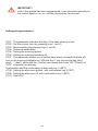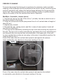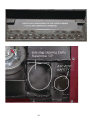
1
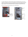
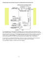
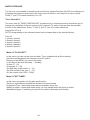
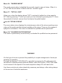
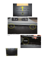
PRODUCTION STOVE AND BOILERS
PELLET AND ALTERNATIVE FUEL
USER MANUAL
Pasian srl
Sogliano Cavour (Le)
www.pasianpellets.it
www.pasian.eu
1
2
Dear customer
Thank you for choosing our product, with which you can burn different types of combustibles:
pellet, washed peanut, almond shells, hazelnuts, pine nuts, corn mixed, always getting the maximum savings.
In this manual you will find all the information you need to know the product, assembly drawings
of stoves and thermostoves and information necessary to perform proper maintenance.
If you have any problems, on customer service area is at your disposal.
In this manual, unless otherwise clearly indicated, the terms like stove, boiler, apparatus,are
used indistinctly product to indicate our generic device.
Best regards
PASIAN SRL
ATTENTION
Pasian reserves the right to make changes to its products that may not be reflected in this manual because it is not substantial. Any aesthetic changes are due to the seasonal nature of
the collections.
Pasian reserves the right to change, at its own sole opinion, all the technical and constructive
details deemed appropriate. All measurements are considered as merely indicative.
3
IMPORTANT
Make sure that the dealer completes the following box with the details of the
authorised specialist who will help you if you have any problems in using your new
pellet stove.
AUTHORISED SPECIALIST
Company_________________________________________________________
Full name_________________________________________________________
Address____________________________N°____________________________
Postal Code______________City______________________________________
Country__________________________________________________________
Tel_______________________________Fax____________________________
All Pasian products are manufactured according to the following directives:
-89/106 CEE (Construction Products)
-89/366 CEE (EMC Directive)
-2004/108 CE (EMC Directive)
-2006/95 CE (Low Voltage Directive)
All PASIAN products are manufactured with attention to the individual components in order to protect both the user and the installer from injury. It is recommended to the authorized personnel to pay particular attention to electrical
connections, especially with regard to the stripped conductor must not escape in
any way from the terminal to avoid possible contact with the live parts of the conductor.
This instruction manual is an integral part of the product: make sure that it always
accompanies the appliance, even if transferred to another owner or user or is
transferred to another place. If it is damaged or lost, please request a copy from
the area technician.
4
INDEX
- Package
- General safety
- Operating Instructions
- Positioning the stove
- Connecting to the network
- Installation the flue
- Drain fumes
- Fuel
- Control panel and remote control
- First Time
- Stove work
- Switching off
- Setting the temperature
- Overview of the flame
- Using the thermostat
- Displays functions on the display
- Periodic cleaning
- Useful in case of problems
- Mounting details of the thermostoves Connection electronic board
- Appendix A
- Warranty
- Technical service
- Appendix: how to clean stoves and boilers
This booklet was produced by the Technical Study Pasian srl.
It reiterates its recommendation to follow the instructions given in the booklet, especially those
relating to the installation of thermostoves and maintenance to ensure proper functioning of nosrti products.
Pasian srl shall be relieved any liability in both civil and criminal damage to property and persons caused by installation, cleaning and maintenance do not conform to what is stated in this
manual
5
Package Contents
Dear customer, will find in the package some supplied accessories:
Brazier for pellet
- Ashes tray
- Power cable
- Pump cable (if applicable, on thermostoves and boilers)
- Deflector slows- fumes (on models MiniBijou, Coccinella, Aurora) Plate slows- fumes * (model-Eletta and Supernova)
- This instruction manual
- Brazier (internal burner)for various combustibles (optional, depending on the version)
* On some models (Eletta and Supernova channeled, etc..) There are two plates: in case of doubt,
consult your dealer or service representative.
6
GENERAL SAFETY RULES
ATTENTION: Read all instructions carefully before installation, use and
maintenance.
-FOR INSTALLATION OF THE BURNER MUST BE STRICTLY OBSERVED THE LAWS FOR
THE DISCHARGE OF FUMES IN FLUE. THE PERIODIC MAINTENANCE OF THE PRODUCT
MUST BE ASSIGNED TO A SPECIALIZED TECHNICIAN IN THE FLUE'S DRAUGHT.
-Connect the suction hose (positioned on the back of the stove)to the outside.
-Put in the upper part of the combustion chamber the deflector “slows-fumes”(the
deflector is a trapezoid metal situated on models ‘MiniBijou’, ‘Coccinella’ and ‘Aurora‘.
-For “Eletta” and “Supernova” models make sure that, before the stard, the ‘slows
fumes’ grate is properly positioned in the upper part of the combustion chamber.
-Do not place in a closed space;avoid burdening the walls,because you risk jeopardizing the proper air flow. Maintenance operations may make necessary interventions on the back of the stove,so it is advised not to block access.
-For the ignition of the stove never use flammable liquids and always keep closed
the door of the fuel tank.
-Do not install the pellet stoves and the boilers in local with little ventilation,or in
places unprotected from the weather and humidity.
-Never open the door of the boiler when the burner is running.
-Turn off the power before removing the burner cover.
-Make sure that the combustible used is of good quality, and that the material doesn’t clog the duct fall of pellets, make sure that the boiler easily reaches the set
temperature, and if necessary correct the calibration of the combustible's supply
in relation to the quality of the same.
7
-Check that the ignition and combustion occur in a regular manner, otherwise,
check the calibration of the burner, check the operation at full, at minimum
power and in the modulation phase .
-If during the ignition phase is after about 10 minutes, not seen the flame, immediately turn off the burner,because the pellet used could have a moisture content too
high and could cause an explosion and barrels within the combustion chamber.
-Do not touch the metal parts and electrical burner or boiler when it is in operation.
-Perform the cleaning operations only when the burner is turned off.Don’t touch the
stove when you are barefoot or when parts of the body are wet or humid.Before any
operation disconnect the power plug, but only after the burner has completed its
shutdown.
-Check the combustion residue, if too hard, you should change the combustible. Its
poor quality can cause the clogging of the grid and the channel of descent of the
pellets with continuous alarm signals.
-The stove must not be used by children or unassisted disabled persons.
-Should be checked periodically by an authorized technician the correct draft in the
boiler. The absence of draft in the chimney (obstruction of the same or of the suction
tube of the combustion air or the presence of residual material in the grate which
stage the holes) alters the functioning of the burner during ignition leads to an excessive dose combustible in the grate.The excessive smoke in the combustion
chamber can create fumes with a violent blaze accompanied by possible outbreaks
- The automatic ignition timing combustible's is very delicate and to avoid problems
in this fase, it is advisable to keep clean the boiler and the burner and ensure the
hermetic closure of the doors of the combustion chamber .If the burn pot is full of
ash, you must remove it, empty it so that liberate all the holes in the base of it and
then put it back in its seat.
-This stove must be destined for the use for which it has been expressly realised.
Pasian disclaims any civil or criminal liability for damage or personal injury caused
by poor installation or resulting from misuse.
-Never carry out repairs. Follow the normal maintenance and cleaning instructions in
this manual. For any need or questions, please contact your dealer.
8
- Incorrect installation or poor maintenance, not conforming to the provisions of this
manual, could cause damage to property, animals and people and invalidate the
product warranty , as well as any kind of tampering, of combustible use inappropriate or without due precaution, or repairs with non-original spare parts is dangerous for the operator's safety and raises Pasian from all liability both civil as
criminal
-Pasian’s pellet burner has been designed to function in any climatic condition (also
critical), however in particularly adverse conditions (strong wind, freezing) the safety
systems may intervene switching off the stove .
If this occurs, contact the technical after-sales service and always disable the safety system.
-Do not pull, disconnect, unplug the cables exit from the burner.Do not leave the
packaging elements within reach of children or unassisted disabled persons.
-In case of fire of flue,use suitable systems to smother the flames and require the
intervention of firefighters.
-before removing the protective panel remove the burner from the power supply:
this operation can only be performed by authorized and qualified personnel.
Caution: Do not use on pressurized boilers or gas boilers
9
Operating Instructions
When purchasing our product, the stove is set for pellet operation, it is advisable, however, to make the proceedings of the switch to a qualified technician.
The choice of the combustible is not binding: you can choose to change or through
the display, if the stove is equipped with the optional "shortcut", or by contacting one
of our technicians.
Before using the command "shortcut" is necessary, in any case, set the second program from one of our authorized technician.
Despite the versatility of our products is recommend to not change constantly the
type of combustible to use in order to not compromise the correct operation of the
stove.
- Do not manually enter the combustible in the brazier (internal burner);
- Before each connection check that the grate is clean;
- Do not wash the interior and exterior with water to prevent corrosion and leakage
on electrical parts, use a soft cloth for the surfaces and only when the stove is cold
and not in use
Positioning the stove
For the positioning of the stove is recommended choosing such a position as to
allow hot air to circulate more easily, encountering the least number of obstacles,
so as to have a uniform distribution of heat.
For the installation of thermostoves (see plumbing diagrams on the following
pages) the ideal point is in the immediate vicinity of the manifolds flow and return
of the heating system.
The installation of the stove and chimney must comply with the rules in force in the
country and restrictions as may be determined by the control orders, also is necessary to check the positioning of the chimneys, of the flue and the same way as installation distances of the exhausts, the distances of legal limitations due to local
regulations or condominium or contracts.
In the vicinity of the heater can be installed appliances working softly or that not
cause any depression in the room from the external environment.It may not be installed in rooms where there are hoods with or without exhaust or ventilation ducts
of the collective type
10
During installation it is necessary to respect the distances shown in the figure
and remind that the maintenance interventions can also be carried out on the
rear side, which must not be at no time blocked.
Beams and wooden or combustible materials must be placed outside the radiation area of the hearth or adequately insulated.
In the case in which the space above the generator exists coverings made of
combustible or heat sensitive must be interposed, a protective membrane made
of insulating material and non-combustible.
Elements of combustible or flammable material like wooden furniture, curtains,
etc.. directly exposed to the hearth must be placed at a safe distance. The installation must guarantee easy access for cleaning the appliance itself, of the
exhaust gas and the flue.
The device must be able to use the necessary air to ensure the orderly functioning through external air intakes. The air vents must have a total free section of
at least 80 cm and must always be completely free.
11
Installation canalized stove
Some stove models are equipped with a further hot air outlet posteriorly: through the
pipes is possible to heated optimally also rooms adjacent to the same stove.
The tubes have a diameter of 80 mm or 100 mm depending on the version and must
be chosen in order to withstand the heat: is therefore necessary to avoid plastic
pipes.
Installation pellet insert on sliding base [page 65]
The stove comes with a iron sliding base that allows the installation in an pre-existing fireplace, that allow to slide so facilitated the insert both for the loading of the
pellets in the tank whether for any maintenance or cleaning at the end of the season.
Installation of boiler insert on fixed base
In the assembly of this model you must prearrange of the lateral inspection and / or
rear for the ordinary and extraordinary maintenance of the unit.
In any case 'should refer to the technical support service.
For optimal mounting and for every doubt about the installation, do always refer to
your dealer and / or technical assistance.
12
Connecting to electric network
- The stove must be connected to an electrical system with conductor to land as required by regulations 73/23 CEE and 2006/95 CE low voltage and must be properly
connected.
- Verify that before turning on the unit, the connection cable not be in contact with
hot parts of the stove or not crushed by it, to avoid dangerous short circuits.
Installation of the flue
The installation of the flue is a very important and delicate because if defective, it can
interfere with the correct operation of the stove: the Installation should be done and
checked by qualified personnel.
Before switching on, make sure that the size and the height of the
flue is adequate for a good draft and that it is not
clogged or incorrectly installed, it must also have a predominantly
vertical and be properly spaced from combustible materials or
flammable materials through an air gap or suitable insulating material.
The draft must be a minimum of 12PA (the optimal is 15Pa).The horizontal sections of
the flue (preferably to be avoided) must have
a slope of between 5-10 ° in such a way as to avoid the deposition of ash; for
lengths> 2m is strongly recommended an increase in the barrel section
flue (ex. from 80 mm to 100 mm).
The vertical section must have a height> 1.5 m and at the base is indispensable
put a T inspection fumes (fitting T 90 ° with inspection)
Use the fewest number of curves possible to avoid obstructions and reduce the
load losses.
Is highly recommended to place a discharge for the collection of ashes
in the inlet point of the flue on the output of pipe union of flue and in the places in which
it could deposit ashes, blocking the flue.
Is, also forbidden not use networks and other devices that may obstruct the end
the flue (including cappelletti for gas boilers), is instead recommend the use
of T chimneys shaped or H or open hats that leave breathe
completely stove in operation (see next page).
To mount the smoke channels, non-fl ammable elements will have to be used, ideal
for resisting fuel products and any condensation.
The use of flexible metal and asbestos cement pipes to connect the appliances to the
flue is forbidden,even for pre-existing smoke channels.
There must be continuity between the smoke channel and the flue so that the flue
does not lean on the generator. The smoke channels must not cross rooms where the
installation of the combustion appliances is not allowed.
13
Detail of a CAP suitable
for closing the FLUE
ABSOLUTELY
NOT SUITABLE
T fitting 90 °for inspection to
be installed at each change of
direction
14
Drain fumes
Directly on the outer wall
The flue gas shown in Fig. 1 is the
solution required for the disposal of
fumes even when the fan is turned off, for
example in case of a power failure.
The difference of the minimum
of 1.5 meters between the rear discharge
and the terminal "T"
external, ensures the fumes
combustion residues.
Vertical duct with external or internal
In fig. 2 is represented the best solution
with exhaust fumes over the roof.
Proceed as in the previous point providing installing a fitting "T" with inspection
plug. The duct internal or external must
be suitably fixed and equipped with a
chimney for the protection from the rain.
On flue
In fig. 3 is seen the discharge of a classic flue.
Use a drain to "T" with the inspection plug and
adequate support brackets .
If the flue is too large is recommend restore it
by introducing a porcelain or a stainless steel
pipe of the maximum diameter of 150 mm,
closing ermetically the input and output parts.
Pasian strongly recommended to follow the patterns of assembling
the chimney illustrated in this booklet in order to not undermine the
proper functioning of our products.
15
At least the flue (absolutely not mechanical type's) must meet some basic requirements:
- Have an internal section equivalent to that of the chimney
- Have a useful outlet section not less than twice the internal stack
- Be so constructed as to prevent the penetration of rain, snow, and foreign bodies in
such a way that even in case of winds in any direction and at any angle to assure
the discharge of the combustion products
- Be positioned in order to ensure an adequate dispersion and dilution of the combustion products and in any case outside the reflux area in which is favored the formation of counterpressures.
The device must also be able to use the necessary to ensure smooth operation. The
air vents must have a total free section of at least 80 cm ² and must be protected
provided that THE PROTECTION NOT REDUCE THE MINI SECTION INDICATED
(DO NOT USE GRIDS).
If the combustion air is withdrawn directly from outside through a pipe is necessary
to fit a curve downwards to protect it against the wind and shall not be positioned
any grill or similar.
16
Combustible
The Pasian production born with the intent to offer equipment for home heating capable of burning perfectly ecological and alternative fuels.
With us not have to choose the combustible but you can use: pellet (but only high
quality), peanut washed and cleaned, mixed corn, almond shells without having to
make structural changes to the equipment. You'll be FREE to use that which best fits
to your needs.
Note that the use of different fuels is SUBJECT to the intervention of an authorized
technician for the calibration of the unit and the use of appropriate braziers : for any
questions you may contact the assistance that will provide all the answers you need.
It's forbidden use different combustibles to your liking and it's necessary to pay close
attention to the various braziers. Any abuse raises Pasian from any liability.
Pellet
Pellets are manufactured by wire drawing compressed sawdust's produced during
processing of the
natural wood, dried and without paint: the compactness of the material is given
from the lignin contained in the wood itself, and not with glues or binders, which is
totally free.
The market offers different types of pellets: the diameter varies between 6 and 8 mm
with a standard length until to 30 mm; if of good quality has a density of around
600 kg / mc3 with a water content of up to 8%of its own weight.
The pellet is ecological, in fact, are reused wood's residues and the emissions reduced; but also economically, in fact to the low operating costs are combined a technical
advantage undeniable: while a good wood can
reach a calorific power of 4.4 kW / kg (after 18 months), the
pellet ensures a calorific value of 5.3 kW / kg. Finally is comfortable the storage,
in dry places, facilitated by packing in 15 kg bags.
ATTENTION
Pasian recommends using only certified combustible.
pellets used must be compliant whit norms:
Ö-Norm M 7135,
DIN plus 51731,
UNI CEN/TS 14961
the use of low quality pellets or other material not conforming,
damage your stoves unctions and can determine the end of the
warranty and annexed producer’s responsibilities.
17
”Nocciolino” (peanut oil)
“Nocciolino” is the result of the separation, through a machinery, of the kernel from the olive pulp,
namely the result of the transformation of waste (pomace) produced by the oil mill.
Used as combustible for boilers, stoves and fireplaces, has granular form and can be sold in bulk
or bagged in comfortable bags of 15 or 20 kg.
Its calorific value is comparable to that of the pellets, equivalent to
about 4800 kcal / kg, and thanks to the cheap purchase cost, there are considerable energy savings, with margins of 80% in terms of saving costs to operate and maintain than traditional fossil
combustible's
The Pasian stoves and boilers are the only ones that can burn many types of chopped combustible, without requiring significant changes.
In the picture you can see the differences between the braziers: on the left for the
pellets and the combustible of similar size and on the right the grate for washed
nocciolino.
On the Eletta/Supernova/CP30 and bigger model the brazier is of round kind.
The transition from pellet to washed nocciolino must still be performed by an
authorized service te-chnician to the control of the flue draft, for the amendments
set to the program-ming and possibly on the grate itself.
18
Corn
Corn is an ecological fuel, with high calorific value, of easy availability and low cost.
Corn or maize is one of the most powerful naturally occurring fuels: you can easily
transport and store and
has a calorific value of about 6200 Kcal / kg (with humidity around 15%).
Corn as the pellets ensures clean combustion, neutral, best of fossil fuels such as
oil, fuel oil, gas and coal, which cause an increase in the content of carbon monoxide and other harmful substances in the atmosphere. Corn is the normal kind: the
price is among the lowest in combustible terms, and cost 18-20 € per quintal, the
yield is more than 6000 kcal / h per kg and burned in stoves and boilers, where the
yield is close to 90%, does not give off fumes and the dry residue is approximately
equal to that of the pellets.
Corn is the normal kind: the price is among the lowest in combustible terms, and
cost 18-20 € per quintal, the yield is more than 6000 kcal / h per kg and burned in
stoves and boilers, where the yield is close to 90%, does not give off fumes and the
Shell
Currently are entering in the market, new environmentally friendly combustibles,
with costs of purchasing virtually nonexistent.
The shells of walnuts, almonds, hazelnuts and pine nuts, properly chopped,
probably are the best natural combusti-ble existent. They haven't practically no
humidity, have a high content of kilocalories, and, as a residue of the food
industry, a very low cost: used in Pasian multifuel stoves and boilers provide
significant savings compared to tradi-tional fuels.
19
Control panel
Key 1: temperature increase
Key 2: lower temperature
Key 3: Set / menu
Key 4: On / off
Key 5: reduce operating power
Key 6: increase operating power
Upper display: State / Power/ Parameter
Lower display: State / Time / Temperature
Remote Control
The remote control (works with batteries MN21 12 volt, not
included) allows to:
- Turn on and turn off the stove: Point the remote control
and press at the same time the top buttons marked "+" sign.
- Vary the power of operation: press the keys 5-6 on the remote control (buttons marked by fire).
- Adjust the thermostat temperature setting: press 1, then
press the keys 1 or 2 (keys marked by the thermometer).
20
First ignition
1.Fill the tank with the combustible (always check that it is filled up to half).
2.Set (with the set button) the type of fuel.
3. Verify that the grate is the right one for the type of chosen combustible and that it
is properly positioned in the seat (on the grate hole corresponding to the resistance).
4.For "MiniBijou", "Coccinella" and "Aurora" models in all versions check the correct
positioning of the deflector in the upper part of the combustion chamber (see figure).
5. For Eletta and Supernova models is necessary to position, prior to ignition, the
plate slows-fumes: the first in the upper part of the combustion chamber (resting on
the side fins , NOT on the brazier), a possible second in the door of upper inspection
(always resting on the side fins and not on pipes).
N.B. models: Eletta and Supernova boiler version, Supernova combined,
CP25 ,CP30(and plus) plate is only one.
6.Check that stove is connected to a power source at 220 V.
7.Set the values of temperature of air and water, as indicated in the following manual.
8. Turn the burner pressing the "key 4" for 3 seconds.
The display will show "LOAD WOOD" and after about 2 min, the fuel will begin to fall
in the brazier, after about 4-5 minutes you will have the ignition of the stove and on
the control panel you will see "ON FIRE" ( stabilization flame's phase). After this
stage, the burner will go into full operation and at this stage it will be possible to vary
the operating power from the KEYS 5/6.
In first hour ventilate the room
9 In "Minibijou","Coccinella" and "Aurora" models, there is a piece of metal shaped
like a trapezoid. It will be inserted into the opening in the upper part of the combustion chamber.
21
In models: [Eletta stove, Eletta Canalized, Eletta combined] Supernova stove and
Supernova Canalized, there are two metal plates: the first place located in the upper
part of the combustion chamber (opening the door glass) on the appropriate side
flaps of support, the second should be seen by opening the inspection door top.
NB. The fumes pass around the plate, front, side and back.
22
-In models: Eletta Idro (thermostove), Supernova Idro (thermostove) and Combined
Supernova, CP25 and CP30 there is only the lower plate.
This shall be placed in the upper part of the combustion chamber (opening the door
glass) on special fins lateriali support.
The models in which there is a single plate are characterized by a flue particular: are
easily recognized because the discharge of the fumes is positioned at the bottom.
23
IMPORTANT
If at the ignition of stove seems that everything works but the pellet is not injected into the combustion chamber is likely to be in action the safety devices.
Check and, if necessary, cleaning the tube bundle of the stove and the flue
to prevent the activation of the safety devices.
In the case of boiler (or thermostove) can be intervened thermostat with manual reset on the rear of the unit: to restore normal operation by press the
corresponding button (protected by a black cap).
The thermostat is easily recognizable: it is characterized, as mentioned, by a
black cap and is positioned on the rear side.
If the problem persists it is advisable to contact the technical assistance.
For each Ignition you need to check the cleaning of the grate, its correct placement of and clean the container compartment of the brazier itself, which
depending on the models is rectangular or round.
24
STOVE IN OPERATING
On the control panel will display "LOAD WOOD" and after about 2 min, the combustible will begin to fall in the brazier, after about 4-5 minutes you will have the starting of the stove and on the control panel you will show "ON FIRE" ( stabilization
flame phase). Once this phase, the stove will go into full operation and at this stage
it will be possible to vary the operating power from the KEYS 5/6 and the temperature by pressing the SET button (3) and then the KEY 1/2. For the first hour it is advisable to ventilate the room.
During normal operation, on the upper part of the display shows the operating power
current (value that can be changed by using the keys 5 and 6 of the control panel),
while in the lower part, temperature achieved around the device.
During this phase the stove (or thermostove) is working to the power set if the ambient temperature is below the set temperature, otherwise the power will automatically switch to the lowest level: in technical terms, we say that the stove is
modulating.
In the case of power cut, when the situation is normalized, the display indicates the
status of a fault with the words "STOP / FIRE" and the suction will be increased for
the expulsion of fumes. Once cooled you reaked re-ignition of the stove.
Switching off
Pressing the KEY 4 on the control panel you can switch off the device.
The display will show "OFF" and the flow of pellets stops automatically. The speed
of the fan suction fumes is automatically increased and the heat exchanger is turned
off when the flue gas temperature is lowered: the total shutdown of the heat generator will occur only below a certain temperature; at this stage is absolutely prohibited
disconnect 'power supply.
Setting the temperature
both the stoves than the thermostoves are equipped with a thermostat with probe for
detecting temperature, that allows to maintain the desired temperature.
During the first use of the product, the pellets start to descend into the combustion chamber after a few minutes, because should become full before the endless screw.
In case of constant misfire, contact your authorized service
technician.
25
To adjust the temperature in the stoves and in the water of the thermostoves,
simply press the KEY 3 (SET) on the control panel (on the lower display will appear the temperature) and to increase or decrease the set value, push the Keys
1 and 2.
To exit programming, press the on / off of the stove.
IMPORTANT
when the set temperature reached, the stove (thermostove) goes into "modulation",in other word, automatically set the fall of combustible using only the required
materials to maintain the set temperature.
In stoves and boilers, above a certain temperature range, after the modulation
phase, it active the automatic turning off indicated by the word "stop fire".
it is possible that during first use the stove emit odors due on paint and silicone used.
THIS DEVICE MUST NOT BE USED AS A WASTE INCINERATOR.
Before lighting the stove you need to check the following points:
- The tank must be full of pellets
- The combustion chamber must be cleaned
- The brazier must be completely free, clean and positioned correctly
- The space below the brazier must be completely free from ash and residues
- Check the hermetic closure of the "fire door", the ash tray and (if present) the
fumes inspection hatch
- Check that the power cord is properly connected
- Position the deflector.
26
FLAME
In order to obtain the proper functioning of our products must be able to "read" the
flame. The PROPERTIES on which the user must pay attention to are essentially:
- form
- color
- character
FORM
In a regular combustion, the flame should have a tapered shape with character "VIVACE", as wide as the brazier from which it develops and the tip tend to vertical or
crushed on the back of the firebox: you must have the feeling that it is pulled upwards and not be direct towards the glass door.
A bad setting of the operating parameters or obstructions in the flue produce a flame
enlarged at the base, with feeble character and tip unguided, slamming against the
glass.
COLOR
A color flame between orange and yellow with dark tip is sign of enlarged flame,
oxygen deficiency and still indicate a problem in combustion.
CHARACTER
- LIVELY: regular combustion;
- SOFT / FEEBLE: irregular combustion.
27
CHRONOTHERMOSTAT
All our products are equipped with a CHRONOTHERMOSTAT that allows to program weekly, for 2 times a day, the time of start and stop of the stove.
To start programming the timer must push for 2 times KEY 3(Set), on the upper display, will show the parameter "UT01" while on the lower will appear the current
day (day 1 = Monday '........ day 7 = Sunday): using the keys 1 and 2 choose the
day that will be stored forever.
if you do not want to use the thermostat you can disable it by setting the value
"UT01" on OFF.
continuing to press the key 3 (set)and at the same time using the keys 1 and 2 can
be programmed parameters “UT02” and “UT03”, at the same way.
The UT04 parameter is reserved for the technical adjustments and should be used
only by technical assistance.
Press repeatedly 3 button (SET) we arrive at "UT05", which indicates the start time
of the stove in the morning, and then "UT06", associated with the shutdown of the
stove in the morning. Both of these settings can be changed by pressing the arrow
keys 1 and 2.
A new pressure of 3 (SET) will bring on "UT07" by pressing 1 will select the day of
the week in the scale of 1 to 7, with key 2 choose if on that day the heater must
ignite or does not turn on in the morning by setting the value to ON or OFF.
For example, if imposed on day 1 on UT07 the value OFF, the stove will not turn on
the morning of Monday, if day4'll set to ON will turn on Thursday morning.
Similarly to what was done for the morning, you can program a second ignition in
the afternoon through parameters "UT08, UT09 and UT10"
DAY 1
MONDAY
TUESDAY
DAY 2
DAY 3
WEDNESDAY
DAY 5
FRIDAY
DAY4
THURSDAY
DAY 6
SATURDAY
DAY 7
SUNDAY
28
IMPORTANT!
even if the ignition has been programmed, it can intervene manually on
the control panel to turn on / off the stove before the time set.
Setting using parameters
UT01 : This parameter indicates the day of the week where you are.
UT02 : Set the current time (by pressing keys 1 and 2);
UT03 : Minute setting (by pressing keys 1 and 2);
UT04 : Technical parameters;
UT05 : Setting the morning ignition;
UT06 : Setting the morning switching off;
UT07 : This parameter allows you to set the days when you want the stove will
turn on the morning timetable set: With the Key 1 you choose the day (day1,
day2,....., day7), while with the 2 button you choose the mode "ON "(Power) or
"OFF" (no power) for that day.
Confirmation and the continuation is done with key 3 (SET).
UT08 : Setting the afternoon ignition, with confirmation key 3 (SET);
UT09 : Setting the afternoon off, with confirmation key 3 (SET);
UT10 : See UT07
29
Display
OFF =STOVE OFF
FUN/ASP = START ASPIRATION CONTROL
LOAD/WOOD = IGNITION CYCLE
FIRE/ON = FLAME STABILIZATION
Po/3° = POWER AND TEMPERATURE DATA
FIRE/STOP = BRAZIER CLEANING CYCLE
MOD/TEMP = TEMPERATURE REACHED MODULATION
MOD/FUMI = MODULATION FOR TEMPERATURE SMOKE'S REACHED
MOD/H20 = MODULATION FOR WATER'S TEMPERATURE REACHED
STOP/FIRE = REACHING MAX TEMPERATURE SETTED
ALAR/FUMI = ALARM EXCESS SMOKE(CLEAN THE FLUE OR CONTACTING TECHNICAL SUPPORT)
ALAR/NO FIRE = IGNITION FAILURE (check the cleaning of the grate and its correct positioning, control the
placement of the deflector plates, check the load of pellets in the tank, if the problem persists contact the technical service)
ALAR/H2O =Excessive water temperature (boilers) (possible presence of air in the system or in the device for
the resolution call the technical support)
ALARM SOND H20 =WATER PROBLEM SENSOR
ALARM SOND FUM = SMOKE PROBLEM SENSOR
ON T = TEMPERATURE PROBLEM SENSOR
COOL FIRE =THERMOSTAT INCORRECTLY INSTALLED
Routine maintenance
Before the ignition must do the following
1. Cleaning the glass (using a dry cloth);
2. Cleaning of the brazier and possible cleaning of the holes;
3. Emptying the ash pan;
4. Suction of the compartment below the grate and of the interior of the combustion chamber;
5. Monitoring for the presence of pellets in the tank
6. Control of the perfect closing of the doors
30
PERIODIC CLEANING
To ensure the proper functioning of our products it is necessary make a periodic
cleaning of the exchanger and of the exhaust of the fumes, so as to remove any deposits of soot which may reduce the heat exchange between the flue gas and the
carrier fluid. We recommend that you do this cleaning monthly or quarterly depending on the quality of the fuel used and the hours of operation.
MiniBijou, Coccinella , Aurora (stove)
1. Unscrew the cap on the side of the stove (*) (4 bolts): the side on which to act is
the same exhaust of the fumes.
2. Clean the vertical tube bundle (are present from 5 to 9 vertical tubes of length of
about 50 cm);
3. Aspirate any residual;
4. Reinstall the cap, making sure to seal this: in case of wear replace it (and call
your service technician)
(*) The cap can be reached by removing the top cover and removing the ceramic on
the side. The top cover is easily removable by unscrewing the screw self-drilling present beneath the stove top and two nuts detectable in the upper part of the tank.
In some models there is also an inner plug: in this case it is possible to perform the
cleaning directly from it.
Even in this case clean the vertical tubes present and aspirate all residues.
Upon reassembly, pay attention to the proper sealing of the cap.
Even in this case clean the vertical tubes present and aspirate the residual
in reassembly, give attention to the proper sealing of the cap.
31
Eletta, Supernova with double plate
1. Open the upper cover;
2. Remove the slows-ashes plate and clean it;
3. Clean with an electrician spring or other appropriate means the vertical tube and reposition the plate;
4. Open the door of the combustion chamber;
5. Remove the slows-ashes plate and clean it;
6. Aspirate any remaining in the combustion chamber and
reposition the plate.
it is highly recommended periodic cleaning of the inlet point of the flues on the filler of the
fumes and the point where they can be deposited ash blocking the flue.
Eletta Supernova ,serie CP with single plate
1. Open the upper cover;
2. Clean with an electrician spring or other appropriate means the vertical tube and
reposition the plate;
3. Open the door of the combustion chamber;
4. Remove the slows-ashes plate and clean it;
5. Aspirate any remaining in the combustion chamber and properly reposition the
plate (almost fully forward).
In addition to the previous points, it is necessary to perform cleaning of the compartments on the sides of the device: they are identifiable behind, right and left of the
ash's tank and need to clean the residual ash and the vertical tube bundle present
in it.
Pasian recommends to carry out the complete cleaning of stoves and thermostove every 2-3 months in case of operation in pellets, at least once a
month in the case of operation at “nocciolino”.
Cleaning should be performed by qualified personnel.
Pasian not liable for damage caused by cleaning's lack or poor maintenance.
WARNING!!!
before carrying out any operation about our products be sure to unplug the stove or
the heater from the power outlet!
32
33
EXTRAORDINARY MAINTENANCE
Door seal: periodically checking and if deteriorated call an authorized technician.
Aspirator: at the end of the season remove all residues.
Cochlea: at the end of season clean the tank and make sure the cochlea is
clean by residues.
Fan and flue smoke tube:Regularly check their cleanliness and proper functioning.
It is advisable that these inspections are carried out by authorized personnel
only and in any case it is appropriate to carry out a general review of the device once a year.
Operation notes
All our products can burn both pellets (up to 8 mm in diameter) that the cited trite
combustibles; for having a correct functioning of the apparatus is necessary use the
braziers suited to the combustible used and modify the operating parameters (entering into the sub menu of programming or using the option direct selection).
Before changing the type of combustible is therefore necessary to perform these two
tasks: setting for each combustible must be performed only by authorized service
personnel. We recommend that you always use a good quality combustible and not
vary continuously it, to not interfere with the correct operation of boilers and stoves.
Pasian recommend to follow as closely as the assembly drawings * of the stoves
contained in this booklet and to conduct periodic maintenance * as indicated in this
manual to ensure proper operation of the products.
Always remember, in the case of thermo-stoves, connect the pump directly on the
electronic control, using the three connectors (Line-Line-Ground Lead) available on
the form.
* Problems of stoves and thermostoves and any damage to property or persons
caused by improper installation or improper maintenance, raise Pasian from any responsibility.
34
advice in case of problems
Anomaly
Possible causes
Possible remedies
pellets not injected into the 1.serbatoio pellets empty 1.Fill tank
combustion chamber
2.motoriduttore cochlea fai- 2. change gear
lure
3. replace the electronic
3.scheda electronic malfun- board
ctioning
4. unlock cochlea
4.coclea locked
5. clean the stove and the
5. stove or chimney
chimney, if you need to call
sporca_INTERVENTO THE service
PRESSURE
6. Unlock thermostat and
6. Speech by resetting ther- contact Technical Support.
mostat.
sudden stop of the stove
1. empty tank
2. pellets not entered
3. intervention safety probe
4. door open or worn Gasket
5. pellets poor
6. low intake of pellets
7. combustion chamber
dirty
8. clogged drain
9. fumes motor not working
1/2. fill tank
3. Let the heater cool
4. close door or replace gasket
5. change the type of pellets
6. assistance
7. clean room
8. clean flue
9. verify the correct operation of the flue gas motor
and replace if necessary
stove is shut down after a
few minutes after power
1. Powering unfinished
2. temporary lack of electricity
3. blocked flue
4. Temperature sensors
faulty
5. pellets of poor quality
6. Failure intake of pellets
1. restore power
2. see manual
3. clean flue
4. replacement
5. change type of pellets
6. pellet hopper fill if empty,
check auger motor and
channel down pellets.
35
Anomaly
Possible causes
the pellets build up in grate, 1. insufficient combustion
glass gets dirty and the
air
flame is weak
2. pellets damp or inadequate or poor-quality
3. fumes motor failure
engine fumes in fault
Possible remedies
1. thorough cleaning stove
and heat exchanger
2. change the type of pellets
3. motor control
1. lack of electrical voltage
2. engine failure
1. check system and fuse
3. defective board
2. replace motor
4. control panel fault
3. replace tab
4. replace panel
Failure to stop combustion 1. temperature sensor fails 1/2/3. check the status and,
air fan
2. fan failure
if necessary, replace filter
3. card fault
The remote control does
not work
1.low batteries
2. remote fault
1. replace batteries
2. replacement remote control
n the automatic position the 1. thermostat set to maxistove always runs at max mum
power
2. room probe fault
3. faulty control panel
1. set the temperature
again
2/3. Verify probe panel and
replace if necessary
Failure to start the stove
1. control system connection
2. replace probe
3. replace fuse
4. clean exhaust duct
5. control the grate and in
the case to change the type
WARNING:
1. lack of electricity
2. flue gases in bulk
3. fuse failure
4. exhaust or flue blocked
5. dirty grate or badly positioned or pellets of poor
qualit
ALL OPERATIONS MUST BE PERFORMED BY A QUALIFIED TECHNICIAN. MAKE SURE BEFORE ANY WORK THAT THE UNIT HAS BEEN DISCONNECTED FROM THE POWER SUPPLY.
36
Mounting details of the thermostoves
The entire production "Pasian IDRO" allows, thanks to exchangers suitably designed, to transfer the heat produced by the combustion to the water, which is heated
and reach, through the hydraulic system, the radiators or the sanitary of the house
(optional).
The ease of installation and the careful design of our products make them suitable
for operation with both traditional equipment (boiler-heating) than with those of the
latest generation (underfloor, ceiling, solar panels, etc..).
Below are diagrams of installation of the systems "HYDRO".
Pasian strongly recommended always to position the circulation pump on the return
line and near the boiler, so that the pump push in the boiler, and to position, in the
case of mounting with closed vessel, an automatic vent valve to the exit of the exit
tube of the thermo-stove.
ATTENTION!
HYDRO VERSIONS ARE SUPPLIED WITHOUT VASE AND CIRCULATOR
[available as an option]
assembly diagram with closed cup
37
scheme with closed cup and kettle for sanitary water
It is important to emphasize that it is necessary to respect the assembly schemes proposed, with the NECESSARY insertion of the circulator on the return
and as the last element before the insertion of the boiler.
At the exit of the flow is necessary an automatic vent valve (valve Jolly) to permit
the air escape which may be present in the boiler.
Boiling water safety
In the case in which there is a shortage of water in the boiler or poor absorption due
to the heat by the plant to block the circulation, may cause an overheating until the
boiling of the water.
A thermostat with manual reset stops the feed motor of the pellet: the thermostat
reset is manual and must be performed by pressing the buttons on the back of the
boiler and covered with screw caps. The intervention of the technical assistance
center for boiler overheating is not covered by warranty.
38
SAFETY FOR CLOSED VESSEL PLANTS
This small summary shows what the UNI 10412-2 indicates as necessary elements for the closed plants
- Safety valve
- Thermostat control of the pump (usually integrated on-board)
- Thermostat alarm sounds
- Temperature display
- Pressure Indicator
- Audible alarm
- Automatic circuit breaker control
- Automatic circuit breaker block (block thermostat)
- Circulation System
- Expansion System
- Dissipation system incorporated with the generator with safety relief valve (self
actuated)
It is important to check periodically the correct pressure of the expansion vessel
and the operation and safety
valves.
39
CONNECTING ELECTRONIC BOARD ON STOVE
40
CONNECTING ELECTRONIC BOARD ON THERMOSTOVES AND BOILER
The installation of a thermostat (available only on thermo-stoves and boilers) [Contact CLEAN OPEN / CLOSE] is accomplished by connecting the two wires to the terminals marked in the figure. To activate the thermostat for a few seconds, press the
power button: after the phase of LOAD WOOD if the thermostat is turned off will
come the words STOP FIRE, which indicates the standby state of the device.
is important to emphasize that these schemes may be regarded as the reference,
since, depending on the version, there may be slight layout changes.
For clarification please contact technical support.
41
LCD display functions
Some models are equipped with a LCD display: in this section is briefly explain its
operation, very similar to the traditional one.
Instructions provided with the stove off
instructions contained in the ignition
phase
42
instructions with stove at work
instructions with stove at modulation mode
MENU
With pressure on the "3" key (MENU) you enter to the menu: This is divided into different voices
and levels that allow you to access the settings and programming the board.
User Menu
To operate in the menu follow the following guidelines:
With the "3" key you enter into the menu or sub menu selected (down one level).
With the button "4" is the inverse operation and exit the menu or submenu where you are (you
are dating
one level)
With the keys "1" and "2" to change the value of a parameter (temperature, time, etc etc)
Use the "5" and "6" you move horizontally between different menu or submenu or between different between different parameters.
43
WATER PRESSURE
The voice is only available in models hydro and boilers (update firmware dec/2010) and allows you
to bypass the pressure control when the termo-stove or boiler is connected to an open vessel.
Press "1" and "2" to make selections "on / off".
"Fans Controller"
The menu item 01 "FANS CONTROLLER" is present only in models ducted air and allows you to
change the ventilation of the two outputs of the channel. For each of the two fans are possible
choices in the table below. Press "1" (fan 2) and "2" (fan 3) to make selections.
setting Fan 2 Fan 3
AUTO corresponding to the selected power level corresponding to the selected power
0 fan off
1 speed 1 speed 1
2 speed 2 speed 2
3 speed 3 speed 3
4-speed 4-speed 4
5 speed 5 speed 5
Menu 02 "CLOCK SET"
In this menu you can set the time and date. The is supplied with a lithium battery
internal clock that permit the autonomy over 3/5 years.
Entering in the MENU you can set the order;
01 the day of the week (Monday ... Sunday)
02 time (0 .. 23)
03 minutes (0 .. 59)
The 04th day of the month (1 .. 31)
The 05th month of the year (1 .. 12)
06, the current year (2000 .. 2099)
Menu 03 "SET TIMER"
In this menu is possible set the start and the stop.
There are eight different possibilities divided into three groups:
Programme Day: 2 starts and stops that are available every day
Weekly program: 4 starts and stops where you can decide when the device is active.
Weekend program: 2 switching on and off only valid for Saturday and Sunday.
44
Menu 3-1 "TIMER MODE"
Allows you to enable and disable all functions globally thermostat. If the value is in the "off" all settings set are disabled.
Menu 3-2 "PROGRAM DAY"
Allows you to activate, deactivate, and set the thermostat's daily functions.
After setting to "on" the first parameter (M-3-2-01) "CHRONO DAY" you can set the two switches
and two shutdowns. For each parameter, you can set the value "off" if you don't want to activate
the timer.
Menu 3-3 "WEEKLY PROGRAM-"
The weekly Group's schedule includes 4 starts and 4 stops. For each pair of on-off you can decide in which days turn ON the pair of corresponding commands.
The first parameter (M-3-3-01) "CHRONO WEEK" allows you to enable or disable all settings in
the weekly time trial.
The first parameter (M-3-2-01) "CHRONO
WEEK" allows you can set 4 starts and 4
stops. For each parameter, you can set the
value of "off" if you do not want to activate
the time parameter, or the timer. After each
pair of timetables there are 7 parameters
corresponding to the 7 days of the week.
Each of these parameters can be set "off"
depending on whether you want to enable or
disable the corresponding program that day of the week. The weekly programmer has 4 independent programs whose effect is made by the combination of 4 individual programs. The weekly
timer can be enabled or disabled. In addition, setting OFF in the voice "time", the clock will ignore
the command Correspondent.
45
The same way for programs 3 and 4.
Menu 3-4 "PROGRAM WEEK-END"
Allows you to enable, disable, and set the chronothermostat function in weekend (ie Saturday and
Sunday). Like the "day" program we have a program of abilitation parameter and 2 pairs of timetables of switching on and off. Schedules will be active as said only on Saturday and Sunday. TIP: In
order to avoid confusion, ignition or shutdown unwanted, activate only one program at a time.
Disable the daily program if you want to use the weekly programme. Turn off the weekend program if you are using the weekly programs in 1,2,3 and 4 parameters. Activate programming weekends only after disabling the weekly schedule.
Menu 04 "SELECT LANGUAGE"
Is it possible select the language among those available.
Menu 05 "STAND-BY MODE"
This menu allows you to activate or deactivate the "STAND-BY" mode.
The stand-by mode indicates a state in which the stove goes out but when the temperature falls
below the set value, the stove is activated automatically .
Once the stand-by menu is set to "On", if the water temperature or the ambient temperature exceeds a certain amount the set values (2 ° C for the ambient temperature and 4 ° for the water temperature) appears on the stove an alternating written "MODULA / STD BY OK". At this point after a
preset time ( 10 minutes for default) if the temperatures do not return to the values set, the stove
turn off and goes into standby mode.
During the shutdown the display shows " WAITING COOLING".
This message is displayed on the display until will occur the conditions for the restart.
46
Menu 06 - "BUZZER MODE"
This mode occurs when is disabled the acoustic signal in case of alarm. When it is
in "On" with the activation of alarms start an acoustic signal.
Menu 07 - "INITIAL LOAD"
Allows you, when the display shows "OFF" a preload of pellets for a time equal to
90". Start by pressing "1" and if you want you can interrupt by pressing the "4". Once
the preload is finished, remove from the brazier the pellet loaded.
Menu 08 "STOVE STATUS"
The menu status stove displays the instantaneous state of the stove reporting some
values of the probe and the internal variables of the stove. There are four pages displayed in succession. This menu is intended for qualified service personnel.
Menu 09, "CALIBRATION TECHNICIAN"
This menu is protected by an access key is intended for qualified service personnel.
WARNING
On this type of stoves is present the possibility of a rapid management of some parameters of operation.
Through the function TYPE PELLET is possible to increase by 5% with each click
the amount of pellets placed inside the brazier, while the function TYPE FIRE leads
to an increase in the speed of the smoke aspirator always 5% with each click.
Use these controls only when absolutely necessary and always after asking always
at the service of technical assistance.
47
WARRANTY pursuant to Legislative Decree February 2, 2002, No. 24
1. Pasian warrants to the purchaser for 24 months the steel structural parts and those not subject
to wear and tear on condition that the buyer fill and save the card as proof of purchase.
This guarantee is valid as long as the buyer:
a) has the unit is installed in accordance with current regulations;
b) makes appropriate use of the device;
c) notify promptly any manufacturing defects.
2. Are excluded from the warranty parts subject to wear, namely: CERAMIC GLASS, GASKETS,
DOOR HANDLES, KNOBS, IN MAJOLICA TILES, SILICONE PAINT, SAFETY FUSE, SEALS
AND INSIDE THE COMBUSTION CHAMBER
3. The warranty does not cover damage caused by:
a) improper installation or improper use of the stove and its components;
b) water or liquid spilled on or pour even accidentally on electronic or electrical components;
c) lightning or power surges;
d) overheating of the stove or use of unsuitable combustiles;
e) impairment of physical or chemical agents;
f) transport or tampering by unauthorized personnel.
4. Pasian do not assumes any responsibility for failure of electrical parts caused by improper connection elettricoo for those where it is not possible accertatre the proper functioning of the electrical installation and grounding correct at time of failure and damage caused by installation of
stoves and connections to chimneys do not conform to what is stated in this booklet.
5. The guarantee covers the delivery and free replacement of defective parts or those considered
as such by our Technical Department. The parts replaced under warranty will be for the period
commencing from the date of purchase always.
6. The replacement of components with non original remove the warranty.
7. There is no compensation for the period of inefficiency of the stove or thermostove awaiting repair.
8. The guarantee is personal and not transferable.
9. If, during the warranty period any defect or failure, the buyer should contact the dealer from
whom the purchase was made, which will check for defects. If the defect is confirmed by the manufacturer, the part will be made available to the customer for free. To facilitate the operations of
replacement please provide the flange standard information at the time of the replace request:
a) name and address of the seller;
b) date of purchase;
c) the name, address and telephone number of the purchaser;
d) the name, address and telefoico installer;
e) date of installation;
f) registration number and model.
10. All transport costs are borne by the customer buyer, such as the right to call, labor costs, travel
expenses and mileage between the home and the customer's home.
11. Pasian guarantees only to the mentioned conditions above and in no event be liable for direct
or indirect damage caused by stoves (stoves) to property or to third parties.
12. The commissioning of the device can be made by authorized technical center or dealer, the
warranty will be valid from the date on your sales receipt or invoice.
48
Receipt WARRANTY (to compile and maintain)
Model and power (thermo) stove
Serial number
Date of purchase
Stamp and signature of retailer
The qualified technician ensures that the installation was carried out in a workmanlike manner
and to have respected all local regulations, including those referring to national and European
standards.
The CAT, after finding that the installation was carried out in accordance with current regulations,
certify that you have made your first start by verifying the proper operation of the stove.
The customer declares that the works have been performed in a workmanlike manner and in accordance with the instructions in this manual and maintenance; certifies that the machine is delivered to the satisfaction of their own and have read the information necessary to make the
correct use and proper operation and maintenance of the stove.
Signature of the Customer
Stamp and signature of technician
Stamp and signature Installer
49
Card before ignition _ Programming
The undersigned authorized technician Pasian __________________, made the first turn
and testing of the pellet stove model number ______________ _____________
Parameter
value
Pr01
Pr01
Pr03
Pr04
Pr05
Pr06
Pr07
Pr08
Pr09
Pr10
Pr11
Pr12
Pr13
Pr14
Pr15
Pr16
Pr17
Pr18
Pr19
Pr20
Pr21
Pr22
Pr23
Pr24
Pr25
Pr26
Pr27
Pr28
Firma_data
It is absolutely forbidden to change the values without the need for technical assistance
authorized Pasian.
50
Model
Power kW
Dimension
and weight
Tank capacity
Chev8 - Minibijou
7,5
50x50x90 cm - 75
kg
circa 14
Coccinella 10/13
10/13
50x57x96.5 cm
90 kg
circa 18
Coccinella 14 can
14
50x57x106.5 cm
110 Kg
circa 18
Coccinella idro
14
50x60x96.5 cm
-120 kg
circa 18
Aurora 18
Aurora 18 can
18
60x57x106,5 cm
130 kg
circa 21
Aurora 20 idro
18
60x62x106,5 cm
150 kg
circa 21
Aurora 24 idro
24
60x74x106,5 cm180 kg
circa 24
Slim
13
107x28x103,5cm
100 Kg
circa 18
Eletta idro
29
51x60x122 cm
200 Kg
circa 30
Supernova 29/can
29
60x60x135,5 cm
190 Kg
circa 40
Supernova idro
34
60x60x128 cm
250 Kg
circa 40
CP25
29
60x60x122 cm
- 200 Kg
circa 30
CP30 - 30 plus
34
60x62x128 cm
- 250 Kg
circa 40 - 70
CP45
45
Inserto 10/can
10
62x62x61 cm
~80 kg
circa 15
Inserto 16
16
69x74.5x71
cm ~100 kg
circa 18
Inserto idro
18
69x75x70 cm
~140 kg
circa 25
[anche NG e Ninfea]
[anche NG e Ninfea]
[anche NG, Ninfea e CP14
[anche CP20]
[anche NG ]
[combinata h 135]
Indicative Values!
70 x85x135 cm
300 kg
51
circa 100
operations performed
on warranty / non-warranty
Date_____________ Type of intervention__________________________________________
Spares and observations ______________________________________________________
___________________________________________________________________________
Signature Customer
Signature and Stamp technical
___________________
____________________________
52
operations performed
on warranty / non-warranty
Date_____________ Type of intervention__________________________________________
Spares and observations ______________________________________________________
___________________________________________________________________________
Signature Customer
Signature and Stamp technical
___________________
____________________________
53
NOTES
____________________________________________________
____________________________________________________
____________________________________________________
____________________________________________________
____________________________________________________
____________________________________________________
____________________________________________________
____________________________________________________
____________________________________________________
____________________________________________________
____________________________________________________
____________________________________________________
____________________________________________________
____________________________________________________
____________________________________________________
____________________________________________________
____________________________________________________
____________________________________________________
____________________________________________________
____________________________________________________
____________________________________________________
____________________________________________________
____________________________________________________
____________________________________________________
____________________________________________________
____________________________________________________
____________________________________________________
____________________________________________________
____________________________________________________
____________________________________________________
____________________________________________________
____________________________________________________
____________________________________________________
____________________________________________________
54
In order to ensure the proper functioning of our products is necessary and indispensable, to perform periodic a cleaning of the heat exchanger and the flue outlet, in order to
remove any deposits of soot that may reduce the thermal exchange between the flue gas
and the carrier fluid.
It is recommended to perform this cleaning on a monthly or quarterly basis in relation
to the quality of the combustibilie used and the device operation’s hours.
We recommend to clean the devices according to the use and the vision of the flame
within the following timetables:
Pellet- 1/2 times for a season
Nocciolino- 2/4 times for a season
Mais- 2/3 times for a season
Triti vari- 2/3 times for a season
The inspection plug is located under the tiles on the sides( or the sheet coating, always
on the Side) or from the side of flue outlet: to localize, needs to remove the tiles from
the same aluminum profiles (or remove the coating).
MODEL : MINIBIJOU
Location of smoke outlet and plug inspection Position: right side
Number of tubes in the pipe bundle: 5
Operations:
1) Lift the “logo/top” on the cover and unscrew the screw underneath it;
2) Unscrew the 6 mm nuts placed inside the pellet tank (the lid of the pellet can be
removed with the utmost attention to the spacers);
3) Lift the lid and place it on the stove’s side (it remains bound to the display cable),
obviously doing a lot of attention;
4) Remove the tiles;
After locating the cap follow these steps:
1) unscrew the cap present on the stove’s side (*) (4 bolts);
2) Clean the vertical tube bundle;
3) Aspirate any residual;
4) Replace the cap being careful to gasket in this (if worn, replace it and contact your
service technician)
On some models there is an inspection plug inside the combustion chamber (fixed
with 4 nuts) that turns out to be very useful for an intermediate cleaning of the tube
bundle.
N.B. In addition to the routine cleaning of the internal exchanger (tube bundle) and
the routine cleaning (brazier etc.), it is necessary to clean the flue on the filler and the
point where the ash can be deposited).
MODEL: Minibijou NG and Chev8
The steps are the same as those described for the model Minibijoux, however, to remove the side trim just remove the fixing screws.
All of the reference images are shown on the following pages
MODEL : Coccinella - Coccinella NG Air [10.13kW]/ CAN[14kW]
Location of smoke outlet and plug inspection Position: right side/ [CAN] side
Number of tubes in the pipe bundle: 7[10.13]/10[CAN]
Operations:
1. Lift the “logo/top” on the cover and unscrew the screw underneath it;
2. Unscrew the 6 mm nuts placed inside the pellet tank (the lid of the pellet can be
removed with the utmost attention to the spacers);
3. Lift the lid and place it on the stove’s side (it remains bound to the display cable),
obviously doing a lot of attention;
4. Remove the tiles;
After locating the cap follow these steps:
1. unscrew the cap present on the stove’s side (*) (4 bolts);
2. Clean the vertical tube bundle;
3. Aspirate any residual;
4. Replace the cap being careful to gasket in this (if worn, replace it and contact your
service technician);
On some models there is an inspection plug inside the combustion chamber (fixed
with 4 nuts) that turns out to be very useful for an intermediate cleaning of the tube
bundle.
N.B. In addition to the routine cleaning of the internal exchanger (tube bundle) and
the routine cleaning (brazier etc.), it is necessary to clean the flue on the filler and the
point where the ash can be deposited).
MODEL : Coccinella Hidro- Coccinella NG Hidro
Location of smoke outlet and plug inspection Position: right side
Number of tubes in the pipe bundle: 12
Operations:
1. Lift the “logo/top” on the cover and unscrew the screw underneath it;
2. Unscrew the 6 mm nuts placed inside the pellet tank (the lid of the pellet can be
removed with the utmost attention to the spacers);
3. Lift the lid and place it on the stove’s side (it remains bound to the display cable),
obviously doing a lot of attention;
4. Remove the tiles;
After locating the cap follow these steps:
1. unscrew the cap present on the stove’s side (*) (4 bolts);
2. Clean the vertical tube bundle;
3. Aspirate any residual;
4) Replace the cap being careful to gasket in this (if worn, replace it and contact your
service technician)
On some models there is an inspection plug inside the combustion chamber (fixed
with 4 nuts) that turns out to be very useful for an intermediate cleaning of the tube
bundle.
N.B. In addition to the routine cleaning of the internal exchanger (tube bundle) and
the routine cleaning (brazier etc.), it is necessary to clean the flue on the filler and the
point where the ash can be deposited).
screw under majolica
nut under cover (in pellet
tank)
MODEL : Aurora Air- Aurora CAN- Aurora Hidro
Location of smoke outlet and plug inspection Position: right side
Number of tubes in the pipe bundle: 9-13 [Hidro 20] - 16 [Hidro24]
Operations:
1. Lift the “logo/top” on the cover and unscrew the screw underneath it;
2. Unscrew the 6 mm nuts placed inside the pellet tank (the lid of the pellet can be
removed with the utmost attention to the spacers);
3. Lift the lid and place it on the stove’s side (it remains bound to the display cable),
obviously doing a lot of attention;
4. Remove the tiles;
After locating the cap follow these steps:
1. unscrew the cap present on the stove’s side (*) (4 bolts);
2. Clean the vertical tube bundle;
3. Aspirate any residual;
4. Replace the cap being careful to gasket in this (if worn, replace it and contact your
service technician)
On some models there is an inspection plug inside the combustion chamber (fixed
with 4 nuts) that turns out to be very useful for an intermediate cleaning of the tube
bundle.
On Hidro models there is an inspection plug to the tube bundle, posed under the first
cover
(for an accurating cleaning of the tube bundle).
N.B. In addition to the routine cleaning of the internal exchanger (tube bundle) and
the routine cleaning (brazier etc.), it is necessary to clean the flue on the filler and the
point where the ash can be deposited).
MODEL : Eletta 29 kW- Eletta NG 29kW
Location of smoke outlet and plug inspection Position: Left side
Number of tubes in the pipe bundle: 18+4 (These last ends, in a compartment accessible from both sides, and the cleaning can be carried out from one side only since the
ash container
is unique)
Operations:
1. Open the upper cover;
2. Clean with an electrician spring or other appropriate means the vertical tube and
reposition the plate;
3. Open the door of the combustion chamber;
4. Remove the slows-ashes plate and clean it;
5. Aspirate any remaining in the combustion chamber and properly reposition the plate
(almost fully forward).
In addition to the previous points, it is necessary to perform cleaning of the compartments on the sides of the device: they are identifiable behind, right and left of the ash’s
tank and need to clean the residual ash and the vertical tube bundle present in it.
N.B. In addition to the routine cleaning of the internal exchanger (tube bundle) and
the routine cleaning (brazier etc.), it is necessary to clean the flue on the filler and the
point where the ash can be deposited).
MODEL : Supernova 34 kW [Normal and Combo version]
Location of smoke outlet and plug inspection Position: Left side
Number of tubes in the pipe bundle: 24+6 (These last ends, in a compartment accessible from both sides, and the cleaning can be carried out from one side only since the
ash container
is unique)
Operations:
1. Open the upper cover;
2. Clean with an appropriate means the vertical tube;
3. Open the door of the combustion chamber;
4. Remove the slows-ashes plate and clean it;
5. Aspirate any remaining in the combustion chamber and properly reposition the plate
(almost fully forward).
In addition to the previous points, it is necessary to perform cleaning of the compartments on the sides of the device: they are identifiable behind, right and left of the ash’s
tank and need to clean the residual ash and the vertical tube bundle present in it.
N.B. In addition to the routine cleaning of the internal exchanger (tube bundle) and
the routine cleaning (brazier etc.), it is necessary to clean the flue on the filler and the
point where the ash can be deposited).
MODEL : Inserto 10 kW [Normal and Canalized version]
Location of smoke outlet and plug inspection Position: Left side
Number of tubes in the pipe bundle: 7
Operations:
1. Slide the insert;
2. Open the cap on the side (fixed with 4 nuts), located on the same side where there is
the fume extractor;
3. Clean with an appropriate cloth means the vertical tube;
4. Aspirate any remaining ashes;
5. close the cover with the appropriate screws, paying carefully to the gasket
In addition to the previous points, it is necessary to perform cleaning of the compartments on the sides of the device: they are identifiable behind, right and left of the ash’s
tank and need to clean the residual ash and the vertical tube bundle present in it.
N.B. In addition to the routine cleaning of the internal exchanger (tube bundle) and
the routine cleaning (brazier etc.), it is necessary to clean the flue on the filler and the
point where the ash can be deposited).
MODEL : Inserto 16 kW
Location of smoke outlet and plug inspection Position: Left side
Number of tubes in the pipe bundle: 7
Operations:
1. Slide the insert;
2. Open the upper cap, fixed with screws or butterflies screw
3. Clean with an appropriate cloth the vertical tube;
4. Aspirate any remaining ashes;
5. Open the cap on the side (posizioned on the side of the flue extractor);
6. Aspirate the residue removed from the tube bundle;
7. Close the cover with the appropriate screws, paying carefully to the gasket;
N.B. In addition to the routine cleaning of the internal exchanger (tube bundle) and
the routine cleaning (brazier etc.), it is necessary to clean the flue on the filler and the
point where the ash can be deposited).
MODEL : Inserto [Hidro]
Number of tubes in the pipe bundle: 13
Operations:
1. Remove the front casing fixed with 4 nuts;
2. Open the cap (also fixed with 4 nuts);
3. Clean with suitable instruments the tube bundle;
4. Remove any residual;
5. Close all caps with the appropriate screws, placing the maximum attention to correct
positioning of the gaskets and the proper sealing of the caps themselves;
N.B. In addition to the routine cleaning of the internal exchanger (tube bundle) and
the routine cleaning (brazier etc.), it is necessary to clean the flue on the filler and the
point where the ash can be deposited).
MODEL : Slim- Slim [Canalized]
Location of smoke outlet and plug inspection Position: Right side (normal version)
Number of tubes in the pipe bundle: 7
Operations:
1. Remove the front grille (where it exits the hot air) fixed with 2 screws;
2. Remove the top cover fixed with 4 nuts (2 on the left side and 2 on the right side);
3. Remove the tiles (move up);
4. Open the cap (fixed with 4 nuts) under the coating on the front side of the flue
extractor;
5. Clean with suitable instruments the tube bundle;
6. Remove any residual;
7. Close all caps with the appropriate screws, placing the maximum attention to correct
positioning of the gaskets and the proper sealing of the caps themselves;
8. Reassemble the stove reinserting the tiles, the top cover and the grid;
On some models there is an inspection plug inside the combustion chamber (fixed
with 4 nuts) that turns out to be very useful for an intermediate cleaning of the tube
bundle.
IMPORTANT:
In this model the outputs of the flue gas ducting and are customizable, so the instructions are only indicative.
For more detailed suggestions, please contact your dealer.
For all boilers of the CP series, the cleaning is done by removing the plug (see the picture), and then acting on the caps indoors.
CP14- Follow Coccinella Hidro’s instructions;
CP 25- Follow Eletta Hidro’s instructions;
CP 30- Follow Supernova Hidro’s instructions;
CP 30 Plus- Follow Supernova Hidro’s instructions;
CP 45- Follow Supernova Hidro’s instructions;
Installing an insert placed on runners
The installation of the insert on runners is a simple task .
It must be secure the base of the insert to the existing base of the chimney with the
appropriate bolts. The base of the chimney itself must be structured so as to be able
to withstand the weight of the insert and to its sliding .
The choice of anchors must be appropriate to the material of the fireplace on which
you install the insert to the order to ensure proper seal and proper alignment of the
parties (recommended measures 12-14 mm).
Operations to be performed :
- Place the insert in the fireplace and pull it complete
- Mark the position of the mounting holes after he " hit " the insert in the fireplace
- Remove the insert, drill the holes and insert plugs seal ,
- Place the insert in the fireplace, pull it out and insert the bolts.
65
Replace the insert making attention to control switch located on the back .
Recommended size piece : between 10-14 mm
Give full attention to the installation level of ' insert ( use a level) for easy scrolling.
Installing a fixed insert
The installation of the fixed insert consists to secure it in the floor of the fireplace.
You must calibrate the size of the blocks based on the difference in height between
the fireplace and the floor insert.
The choice of anchors must be appropriate to the material of the fireplace on which
you install the insert to ensure proper seal and proper alignment of the parties ( the
recommended measures 12-14 mm).
55
Pasian srl
Sogliano Cavour (le)
Tel. +39 (0)836543750 - (0)836 1955170
Fax +39 (0)836543315 - (0)836 1956195
www.pasianpellets.it - www.pasian.eu
info@pasianpellets.it - info@pasian.eu
56