1
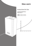
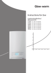
Flexicom sx
High Efficiency Condensing System Boilers
Instructions for Use
To be left with the user
Glow-worm, Nottingham Road, Belper, Derbyshire. DE56 1JT
www.glow-worm.co.uk
www.glow-worm.co.uk
0020003657
1
2
WARNING
GAS LEAK OR FAULT
Turn off the gas emergency control valve immediately. Eliminate all sources of ignition, i.e.smoking,
blowlamps, hot air guns etc. Do not operate electrical lights or switches either on or off.
Open all doors and windows, ventilate the area.
SHEETMETAL PARTS
This boiler contains metal parts (components) and care should be taken when handling and cleaning,
with particular regard to edges.
SEALED COMPONENTS
Technical helpline: 01773 828300
Under no circumstances must the User interfere with or adjust sealed parts.
Customer service call: 01773 828100
General and Sales enquiries Tel: 01773 824639 Fax: 01773 820569
www.glow-worm.co.uk
18sx
G.C. No. 41-315-72
www.glow-worm.co.uk
0020003657-03 02.06
Position of name badge
3
4
Maintenance
Boiler Safety Devices
Boiler Design
Important Information
9
8
7
6
5
CONTENTS
Boiler Operation
These instructions are an integral part of the boiler and must, to comply with the current issue of the Gas Safety
(Installation and Use) Regulations, be left with the user.
Please read these instructions and follow them carefully for the safe and economical use of your boiler.
www.glow-worm.co.uk
Gas Category
Important Information
Gas Safety (Installation and Use) Regulations
Testing and Certification
CE Mark
Any alteration not approved by Glow-worm, could invalidate the
certification, boiler warranty and may also infringe the current issue
of the statutory requirements.
It is important that no alteration is made to the boiler unless
approved, in writing, by Glow-worm.
This boiler is certificated to the current issue of EN 483 for
performance and safety.
This boiler is for use only on G20 natural gas.
In your own interests and that of safety, it is the Law that ALL gas
appliances have been installed by a competent person in
accordance with the current issue of the regulations.
Control of Substances Hazardous to Health
Under Section 6 of The Health and Safety at Work Act 1974, we are
required to provide information on substances hazardous to health.
The adhesives and sealants used in this appliance are cured and give
no known hazard in this state.
The boiler MUST be earthed.
Electrical Connection
The boiler MUST be connected to a permanent 230V ac, 50Hz
supply.
5
3. Directive 89/336/EEC on the approximation of the Laws of the
Member States relating to electromagnetic compatibility.
2. Directive 73/23/EEC on the harmonisation of the Laws of the
Member States relating to electrical equipment designed for use
within certain voltage limits.
1. Directive 90/396/EEC on the approximation of the laws of the
Member States relating to appliances burning gaseous fuels.
The CE mark on this appliance shows compliance with:
Product/production certified by: Notified body 0086.
Type test for purposes of Regulation 5 certified by: Notified body
0087.
This boiler meets the requirements of Statutory Instrument, No. 3083
of the Boiler (Efficiency) Regulations, and therefore is deemed to
meet the requirements of Directive 92/42/EEC on the efficiency
requirements for new hot water boilers fired with liquid or gaseous
fuels.
Connection of the whole electrical system of the boiler, including any
heating controls, to the electrical supply must be through one common
isolator and must be fused to 3 Amps maximum.
The colours of three core flexible cable are, blue - neutral, brown - live,
green and yellow - earth.
All connections must be routed through the Installer Interface.
IMPORTANT NOTE
ALL electrical connections to the boiler
must be permanently fixed to a wall or a
sturdy support feature.
www.glow-worm.co.uk
Description
Boiler Design
These boilers are designed for use as part of a sealed water
central heating system with fully pumped circulation. The
pump, expansion vessel and associated safety devices are all
fitted within the boiler.
The daily pump exercise combined with the built-in frost
sensor will help to maintain and protect the boiler.
Once the controls are set the boiler operates automatically.
Compartment or Cupboard Installations
Ventilation is not required for compartment or cupboard
installations.
Do not use the compartment or cupboard for storage.
The minimum clearances to fixtures are shown in diagram 1.
Pluming from flue terminal
Like all condensing boilers it will produce a plume of
condensation from the flue terminal in cool weather. This is
due to the high efficiency and hence low flue gas temperature
of the boiler. It is normal and not a fault indication.
Electrical Supply Failure
150
5
600
5
150
5
compartment door can be placed a minimum of
* A removable
5mm in front of the appliance but there must be a
www.glow-worm.co.uk
clearance of 600mm minimum from a fixed surface
The boiler will not work without an electrical supply and
normal operation of the boiler should resume when the
electrical supply is restored.
Diagram 1
6
If the boiler does not resume normal operation, check the
external controls, it may be necessary, to "reset" the boiler,
refer to the following section, "Boiler Safety Devices".
12652
Overheat Reset
Condensate Drain Blockage
Boiler Safety Devices
The boiler software is designed to recognise the potential for
an overheat lockout and will shutdown before this happens.
To restart the boiler, press the reset button, see diagram 2.
RESET
°
DIGITAL DISPLAY
A safety discharge valve and discharge pipe is fitted to the
boiler. This valve MUST not be touched. If there is any
discharge from the pipe, switch off the boiler electrical supply,
then call your Installation/Servicing company or Glow-worm
service.
Safety Discharge Valve
As a safety feature the boiler will stop working if the condensate
drain becomes blocked. During freezing conditions this may
be due to the forming of ice in the condense drain external to
the house. Release an ice blockage by the use of warm cloths
on the pipe. The boiler should then restart. Contact your
installation/servicing company or Glow-worm service if the
fault persists.
If, however the boiler fails to resume normal operation and all
services and demands are calling for duty then call your
Installation/Servicing company or Glow-worm service.
Frost Protection
With the gas and electric supplies ON and irrespective of any
room thermostat setting, the integral frost protection device
will operate the pump when the temperature of the boiler
water falls below 8OC.
A timer is used so that the temperature can be checked
periodically. After 10 minutes the pump will be stopped if the
temperature is higher than 10OC or has already reached
35OC.
The burner will only activate if the boiler temperature does
not reach 10OC after 30 minutes or at any time if the
temperature drops to 5OC.
The burner will switch off when the temperature reaches
35OC.
NOTE: Any other exposed areas of the system should be
protected by a separate frost thermostat.
www.glow-worm.co.uk
Diagram 2
7
13124
Frost Protection
Maintenance
Servicing
If the mains electricity and gas services are to be turned off for
any long periods during severe weather, it is recommended
that the whole system, including the boiler, should be drained
to avoid the risk of freezing.
If replacement parts are required contact Glow-worm’s own
service organisation using the telephone number on the
inside front cover of this booklet.
REMEMBER, When replacing a part on this boiler, use only
spare parts that you can be assured conform to the safety and
performance specification that we require. Do not use
reconditioned or copy parts that have not been clearly
authorised by Glow-worm.
Spare Parts
The draining, refilling and pressurising MUST be carried out
by a competent person, contact your installation/servicing
company.
Sealed Water Systems
To ensure the continued efficient and safe operation of the
boiler it is recommended that it is checked and serviced at
regular intervals. The frequency of servicing will depend upon
the site conditions and usage, but in general, once a year
should be enough.
If this boiler is installed in a rented property in the UK there is
a duty of care imposed on the owner of the property by the
current issue of the Gas Safety (Installation and Use)
Regulations, Section 35.
Servicing/maintenance should be carried out by a competent
person in accordance with the rules in force in the countries
of destination.
To obtain service, please call your installer or Glow-worm’s
own service organisation using the telephone number on the
inside front cover of this booklet.
Cleaning
The boiler casing can be cleaned using a mild liquid detergent
with a damp cloth, then a dry cloth to polish.
Please quote the name of the boiler, this infomation will be on
the name badge on the front case.
If in doubt seek advice from the local gas company or Glowworm’s own service organisation using the telephone number
on the inside front cover of this booklet.
www.glow-worm.co.uk
Do not use any form of abrasive or solvent cleaner as you may
damage the paintwork.
8
4.
3.
2.
1.
To operate the boiler follow the instructions as
described on the following pages.
The digital display will indicate the system pressure,
which should read at least 0.7bar (recommended
1.0bar).
Check that the electrical supply to the boiler is ON and
there is no demand from the any external controls.
If you are in any doubt about the boiler being filled
with water contact your installer or Glow-worm's own
service organisation using the telephone number on
the inside front cover of this booklet.
Do not operate the boiler without water.
Check that all isolating valves and the Gas cock,
on the boiler are open, see diagram 3.
Boiler Operation
5.
Set the external controls as required.
Isolating Valves
6.
www.glow-worm.co.uk
ISOLATING VALVES
CH FLOW & RETURN
ISOLATING VALVES
(shown closed)
GAS COCK
(shown closed)
Diagram 3
9
13058
Description
Boiler Operation - User Controls
The boiler User controls consist of a "MODE" button, refer
to diagram 6, which, when pressed and held for 2
seconds, enters the Central Heating function indicated by a
flashing radiator symbol. After 10 seconds of inactivity the
display will reset to indicate the water pressure.
The "SELECTOR" buttons are used to turn OFF and set
the Central Heating temperature (38 - 82OC).
If a fault occurs, indicated by a flashing 'F' and code
number, press the reset button positioned below the digital
display.
www.glow-worm.co.uk
If a fault persists, indicated by a flashing 'F' and code
number, contact your installer/service provider using the
telephone number on the inside front cover of this booklet.
10
13123
DIGITAL DISPLAY
MODE BUTTON
SYSTEM PRESSURE
TEMPERATURE
CENTRAL HEATING
MODE BUTTON
1. Press and hold for 2
seconds for Central Heating
°C
bar
BURNER DEMAND
SELECTOR BUTTONS
Holiday Mode:
Central Heating
de-activated. System
pressure indicated.
Central Heating active with
demand shown by the
temp. & burner symbol
indicate that the burner
is on.
Central Heating activated
but with no demand,
system pressure indicated.
OPERATION
Boiler Operation - Display
°
RESET BUTTON
SELECTOR BUTTON FUNCTION
1. Increase temperature
SELECTOR BUTTON FUNCTION
1. Decrease temperature
2. De-activate Central Heating
www.glow-worm.co.uk
OFF
bar
°C
bar
11
Diagram 6
13118
12
Because of our constant endeavour for improvement, details may vary slightly from those shown in these instructions.
www.glow-worm.co.uk
www.glow-worm.co.uk