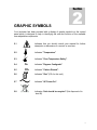
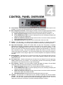
1
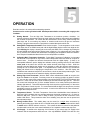
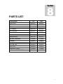
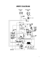
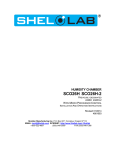
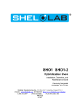
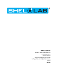
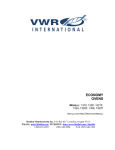
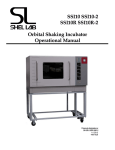
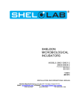
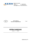
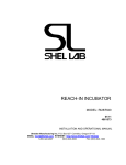
REACH-IN DRY CO2 INCUBATOR SCO31 SCO31-2 SCO40 SCO41-2 PREVIOUSLY DESIGNATED AS 2428 2428-2 2440 2440-2 Revised 12/2013 4861504 INSTALLATION AND OPERATION MANUAL Sheldon Manufacturing Inc. P.O. Box 627 Cornelius, Oregon 97113 EMAIL: tech@Shellab.com INTERNET: http://www.Shellab.com/~Shellab 1-800-322-4897 (503) 640-3000 FAX (503) 640-1366 TABLE OF CONTENTS SECTION 1.0 RECEIVING AND INSPECTION SECTION 2.0 GRAPHIC SYMBOLS SECTION 3.0 INSTALLATION SECTION 4.0 CONTROL PANEL OVERVIEW SECTION 5.0 OPERATION SECTION 6.0 MAINTENANCE SECTION 7.0 TROUBLESHOOTING SECTION 8.0 PARTS LIST UNIT SPECIFICATION SCHEMATICS These units are TUV CUE listed as CO2 incubators for professional, industrial, or educational use where the preparation or testing of materials is done at approximately atmospheric pressure and no flammable, volatile, or combustible materials are being heated. These units have been tested to the following requirements: CAN/CSA C22.2 No. 61010-1:2012 CA N/CSA C22.2 No. 61010-2-010 + R:2009 UL 61010-1:2004 + R:2005-07 + R:2008-10 UL 61010A-2-010:2002 UL 61010-1:2012 EN 61010-1:2010 EN 61010-2-010:2003 IEC 61010-1:2010 IEC 61010-2-010:2003 2 1 Section RECEIVING AND INSPECTION IMPORTANT: READ THIS INSTRUCTION MANUAL IMMEDIATELY. Your satisfaction and safety require a complete understanding of this unit, including its proper function and operational characteristics. Be sure operators are given adequate training before attempting to put the unit in service. NOTE: This equipment must be used for its intended application; any alterations or modifications will void your warranty. 1.1 Inspection: The carrier, when accepting shipment, also accepts responsibility for safe delivery and is liable for loss or damage claims. On delivery, inspect for visible exterior damage, note and describe on the freight bill any damage found and enter your claim on the form supplied by the carrier. 1.2 Inspect for concealed loss or damage on the unit itself, both interior and exterior. If any the carrier will arrange for official inspection to substantiate your claim. Save the shipping crate until you are sure the unit has been delivered in good condition. 1.3 Return Shipment: If for any reason you must return the unit, contact your customer service representative for return authorization and supply data plate information. Please see the manual cover for information on where to reach customer service. 1.4 Make sure that all of the equipment indicated on the packing slip is included with the unit. Carefully check all packaging before discarding. These units are equipped with 6 shelves, 24 shelf clips, CO2 tubing kit and 4 adjustable feet. 3 2 Section GRAPHIC SYMBOLS Your incubator has been provided with a display of graphic symbols on the control panel which is designed to help in identifying the use and function of the available user adjustable components. 2.1 Indicates that you should consult your manual for further description or discussion of a control or user item. 2.2 Indicates "Temperature" 2.3 Indicates "Over-Temperature Safety". 2.4 C Indicates "Degrees Centigrade". 2.5 CO2 Indicates "Carbon Dioxide". 2.6 Indicates "Gas" (CO2 for this unit.) 2.7 Indicates "AC Power On". 2.8 Indicates “Unit should be recycled” (Not disposed of in land-fill) 4 3 Section INSTALLATION Local city, county or other ordinances may govern the use of this equipment. If you have any questions about local requirements, please contact the appropriate local agency. Installation may be performed by the end user. It is unnecessary for this unit to be installed by a technician. Under normal circumstances this unit is intended for use indoors, at room temperatures between 15 and 30C, at no greater than 80% Relative Humidity (at 25C) and with a supply voltage that does not vary by more than 10%. Customer service should be contacted for operating conditions outside of these limits. 3.1 Power Source: The power supply must be properly grounded (earthed) and correctly sized to match the unit data plate rating. VOLTAGE SHOULD NOT VARY MORE THAN 10% FROM THE DATA PLATE RATING. These units are intended for a 50/60 Hz application. If supplied with a detachable cord set, plug the female end into the inlet on the unit and the male plug into the supply. Assure that units requiring a fuse have a fuse installed. This fuse may be at the inlet or part of the cord set male plug. Note that electrical supply to the unit must conform to all national and local electrical codes. 3.2 Location: When selecting a site for the unit, consider conditions which may affect performance, such as heat from steam radiators, ovens, autoclaves, etc. Avoid direct sun, fast-moving air currents, heating/cooling ducts, and high-traffic areas. To ensure air circulation around the unit, allow a minimum of 10cm of clearance between the incubator and surrounding walls, or partitions which might obstruct free air flow. 3.3 Lifting/Handling: These units are heavy and care should be taken to use appropriate lifting devices that are sufficiently rated for these loads. Units should only be lifted from their bottom surfaces. Doors, handles and knobs are not adequate for lifting or stabilization. The unit should be completely restrained from tipping during lifting or transport. All moving parts, such as shelves and trays should be removed and doors need to be positively locked in the closed position during transfer to prevent shifting and damage. 3.4 Leveling: The unit must sit level and solidly. Leveling feet are supplied and should be installed in the four holes in the bottom corners of the unit. With the feet installed and the unit standing upright, each foot can be raised by turning it in a counterclockwise direction. An opposite clockwise rotation will lower that foot. Adjust the foot at each corner until the unit stands level and solid without rocking. 3.5 Cleaning: The unit chamber should be cleaned and sterilized prior to operating. Use a suitable disinfectant that is appropriate to your application. DO NOT USE chlorine-based bleaches or abrasives as this will damage the interior chamber. DO NOT USE spray cleaners that might leak through openings and cracks and get on electrical parts or that may contain solvents that will harm the coatings. Special care should be taken when cleaning around sensors to prevent damage. Warning: Never clean the unit with alcohol or flammable cleaners with the unit connected to the electrical supply. Always disconnect the unit from the electrical service when cleaning and assure all volatile or flammable cleaners are evaporated and dry before reattaching the unit to the power supply. 3.6 Shelves and Interior Parts: Shelving and clips are supplied with the unit. See Figure 1. 5 Figure 1 6 4 Section CONTROL PANEL OVERVIEW 4.1 Power Switch: The main power I/O (On/Off) switch on the panel controls all the power to the incubator. It must be in the I/On position before any systems are operational. 4.2 Main Temperature Controller: Marked C, this controller contains the digital temperature display, UP and DOWN arrow pads, HIGH and LOW alarm indicators and an alarm MUTE indicator. A. B. C. D. Digital Temperature Display indicates the actual temperature within the chamber to .1C. UP and DOWN Arrow Pads are used for inputting the set point, calibrating the display and muting or unmuting the audible alarm. HIGH and LOW Alarm Indicators will light whenever there is an alarm condition associated with the temperature within the incubator. Alarm MUTE Indicator will light whenever the audible alarm has been muted. 4.3 Heating: This pilot lamp is on whenever the temperature controller is energizing the heating element. The element will go on and off as heat is needed to maintain the set point temperature. 4.4 High Limit Thermostat: Marked SET HIGH LIMIT, the High Limit Thermostat is completely independent of the Main Temperature Controller and functions as an override control. If at any time the Main Temperature Control fails in the On position, the chamber temperature is then limited to the High Limit Thermostat set point which is manually set approximately 1C above the Main Controllers set point. Note that the HEATING indicator will continue to function under the control of the High Limit Thermostat. It is not recommended that the unit be allowed to operate for an extended period of time using the High Limit to control temperature as temperature uniformity will suffer. 4.5 Safety Activated: This pilot lamp is on whenever the High Limit Thermostat has taken control of the incubator and shut down the elements. Under normal operating conditions this pilot lamp should never be on. 4.6 CO2 Sample Port: Chamber atmosphere can be taken from the Sample Port at the upper front corner on the left side of the chamber. CO2 concentration can then be checked using a FYRITE gas analyzer or other instrument such as a gas chromatograph. 4.7 CO2 Controller: Marked % CO2, this controller contains the digital CO2 display, UP and DOWN arrow pads, HIGH and LOW alarm indicators, and alarm MUTE indicator. A. Digital CO2 Display indicates the % CO2 content within the incubator chamber to .1%. B. UP and DOWN Arrow Pads are used for inputting the set point, calibrating the display and muting or unmuting the audible alarm. C. HIGH and LOW Alarm Indicators will light whenever there is an alarm condition associated with the CO2% within the incubator chamber. D. Alarm Mute Indicator will light whenever the audible alarm has been muted. 4.8 Injection: This pilot lamp is on whenever the CO2 controller is injecting CO2 into the incubator chamber. Note that there is a rocker switch located at the base of the control panel and just above the door. The door, when opened, trips the switch and disengages injection of CO2. This is an added feature that saves consumption of gas while loading/unloading the chamber. 7 5 Section OPERATION Read this section in its entirety before attempting operation. Connect service cord to grounded outlet. Set temperatures before connecting CO 2 supply to the incubator. 5.1 5.2 5.3 5.4 5.5 5.6 5.7 Getting Started: Turn the High Limit Thermostat to its maximum position, clockwise. An accurate reference thermometer should be used inside the chamber when setting and calibrating the incubator temperature. Be certain that the thermometer can be easily viewed through the glass door and is not touching any shelves or chamber walls as this will give an inaccurate reading. Taping the thermometer to a petri dish is a method that works well for this. Setting Main Temperature Controller: Enter desired set point. To set temperature on the control press either the UP or DOWN arrow pad until the digital display begins to blink from bright to dim. While blinking the display is showing the current set point which can be changed by pushing the UP and DOWN arrow pads until the desired value is reached. If no adjustments are made within five (5) seconds, the controller will default back to displaying the temperature within the chamber. Once set point is established allow 24 hours for the temperature to stabilize. Calibrating Main Temperature Controller: During Main Temperature Calibration it is important that the door not be opened for any reason, and the temperature has been stabile at set point for several hours. Compare the reference thermometer with the digital display. If there is an unacceptable difference put the display into calibrate mode by pressing both the UP and DOWN arrow pads at the same time until the two outside decimal points begin to flash. While the decimal points are flashing the display can be changed to match the reference thermometer by pushing the UP or DOWN arrow pads. If no adjustments are made within five (5) seconds the display will default back to displaying the temperature in the chamber. After the display has restabilized and maintained set point for several hours, check the actual temperature again. If the reference thermometer does not match the display, repeat the calibration. Setting High Limit Thermostat: With the Main control calibrated and stabile at set point, the High Limit needs to be adjusted. Previously turned to its maximum position as stated in section 5.1, now turn the control knob counterclockwise just until the SAFETY ACTIVATED indicator light comes on. Next, turn the control knob clockwise just until the indicator light goes off. Then turn the control knob clockwise two (2) of the smallest divisions on its scale past the point where the indicator light went off. This should adjust the High Limit set point to approximately 1C above the Main Temperature Control set point. It is recommended that the High Limit set point be checked periodically to assure no changes have occurred. A mark on the dial will aid for future reference if changes to this set point occur. Temperature Alarms: The Main Temperature Control has visual/audible alarm indicators for HIGH and LOW conditions that are activated whenever the actual temperature is 1C above or below the set point. There is a built in delay of fifteen (15) minutes on the occurrence of the audible LOW alarm. This prevents the alarm from activating every time the door is opened and the temperature drops. Muting Audible Alarm: The audible alarm can be muted for a single alarm occurrence by pressing and holding down either the UP or DOWN arrow pad for several seconds until the alarm is muted and the MUTE indicator comes on. This means the alarm is muted for that particular condition while it exists, but is not muted indefinitely or for a separate condition that may occur. CO2 Supply: As stated at the beginning of this section, do not connect the CO2 supply to the incubator until the temperatures have been set. Use only MEDICAL GRADE CO2 with an in-line 8 5.8 filter (provided with your tubing kit) from the tank to the incubator. These incubators use CO 2 in small quantities. Precise metering of input is vital for maximum performance and only a twostage CO2 pressure regulator is recommended. Note that some single-stage CO2 pressure regulators have two (2) gauges; be certain you are using only a two-stage regulator. CO2 Regulator: The high-pressure stage of the regulator coming direct from the supply tank must have a range from 0 to at least 2000 PSI (actual tank pressure as read on the gauge). The lowpressure stage should have a range from 0 to at least 40 PSI. The low-pressure gauge indicates actual CO2 pressure into the incubator. Connect the CO2 supply from the low-pressure stage of the regulator to the 3/8" inlet fitting on the left side of the unit marked CO2 TO CHAMBER. CAUTION: CO2 pressure to the incubator inlet is rated from 15 to 20 PSI. DO NOT exceed 20 PSI. 5.9 CO2 Principle of Operation: The microprocessor CO2 control system interprets the information from the CO2 sensor, displays the CO2 concentration directly on the digital display, reads the set point and controls the percentage of CO2 in the incubator chamber. The infrared (IR) sensor operates under the principle that a certain frequency of infrared light is absorbed by CO2. The more CO2 present in the chamber the more light is absorbed. The IR sensor is only sensitive to CO2, so its accuracy is consistent no matter what the conditions are in the incubator. 5.10 Setting CO2 Controller: To set the CO2 percent you desire press either the UP or DOWN arrow pad until the digital display begins to blink from bright to dim. While blinking, the display is showing the current set point which can be changed by pushing the UP and DOWN arrow pads until the desired value is reached. If no adjustments are made within five (5) seconds, the controller will default back to displaying the parameter within the chamber. Once set point is established allow several hours for CO2 to stabilize. 5.11 Calibrating CO2 Controller: During CO2 calibration it is important that the door not be opened for any reason and the CO2 has been stabile for several hours. Using a Digital or CO2 Fyrite gas analyzer, measure the actual CO2% within the chamber via the sample port on the left side of the unit. If there is an unacceptable difference between the display and the CO2 analyzer, get the unit into calibration mode by pressing both the UP and DOWN arrow pads at the same time until the decimal points begin to flash. While the decimal points are flashing the display can be changed to match the analyzer reading by pushing the UP or DOWN arrow pads. If no adjustments are made within five (5) seconds the display will default back to displaying the CO2% in the chamber. After the display has restabilized and maintained set point for several hours, check the actual CO2% again. If the CO2 analyzer does not match the display, repeat the calibration. NOTE: When using the CO2 analyzer, insure that gas is not being injected while the reading is being taken. 5.12 CO2 Alarms: The CO2 controller has visual/audible alarm indicators for HIGH and LOW conditions that are activated whenever the actual CO2 content is 1% above or below the set point. There is a built in delay of fifteen (15) minutes on the occurrence of the LOW audible alarm. This prevents the alarm from activating every time the door is opened and the CO2 content drops. See Section 5.6 for MUTING the audible alarm. Accessory Outlets: There are four (4) outlets inside the chamber for use with equipment not exceeding 1 amp. Note that equipment in the chamber may provide additional heat that could affect the temperature range of the incubator. It is recommended that testing be done with the incubator and any additional equipment to insure that the desired operating conditions can be met. This incubator comes equipped with a 4-20mA board and interface to facilitate communication with an in-house monitoring system. The use of the 4-20mA feature will vary depending on the facility requirements and configuration. If you have any questions about the use of this feature in your application, please email our technical service department at tech@shellab.com or call us at 1.800.322.4897. The values for the conversion are located on the specification page of this manual. CAUTION: this incubator is capable of safely operating at conditions that might otherwise damage certain accessory equipment. Make absolutely certain your accessory equipment is capable of operating under the conditions you intend to run your incubator. 9 6 Section MAINTENANCE NOTE: Prior to any maintenance or service on this unit, disconnect the service cord from the power supply. 7.1 Cleaning: Cleaning and decontamination are recommended on a regular basis. To prepare the incubator for cleaning remove all interior parts such as shelves and shelf clips. First clean the chamber with soap and water, rinse and let dry. To decontaminate use a solution that is appropriate to your application. DO NOT USE chlorine-based-bleaches or abrasives as this can damage the interior chamber. DO NOT USE spray cleaners that might leak through openings and cracks and get on electrical parts or that may contain solvents that will harm coatings. WARNING: Never clean the unit with alcohol or flammable cleaners with the unit connected to the electrical supply. Always disconnect the unit from the electrical service when cleaning and assure all volatile or flammable cleaners are evaporated and dry before reattaching the unit to the power supply. 7.2 Check CO2 supply periodically; do not let it run out. (Automatic tank switches are available from your dealer.) 7.3 Periodically check CO2 supply lines and connections for leaks. Use a liquid soap solution to detect leaks. Wet supply line and connections and look for bubbles. 7.4 Keep the CO2 flow system free of impurities. Erratic CO2 control is usually traceable to the CO2 pressure regulator on the tank, impurities in the tank, or impurities in the solenoid valve. Replace the CO2 in-line filter (2800525) every six (6) months or when the filter has become noticeably dirty on the upstream side. 7.5 There is no maintenance required on electrical components. If the unit fails to operate as specified see Section 7.0 Troubleshooting, before calling for service. If technical assistance is required, see the manual cover for information on where to reach customer service. 10 7 Section TROUBLESHOOTING The incubator is designed so that no internal electrical servicing should be requires under normal conditions. If electrical servicing is necessary, it should be performed by qualified service personnel. FOR PERSONAL SAFETY, ALWAYS DISCONNECT THE POWER BEFORE SERVICING. Always make a visual inspection of the incubator and control console when troubleshooting. Look for loose or disconnected wires or tubing, which may be the source of the trouble. TEMPERATURE Temperature too high 1/ controller set too high-see section 5.2 2/ controller failed on – call Customer Service 3/ wiring error – call Customer Service Display reads "HI" or "400"+ probe is unplugged-call Customer Service Chamber temp spikes over set point and then settles to set point recalibrate – see section 5.3 Temperature too low 1/ high limit set too low – see section 5.4 2/ controller set too low – see section 5.2 3/ unit not recovered from door opening – wait for display to stop changing 4/ unit not recovered from power failure or being turned off – incubators will need 24 hours to warm up and stabilize 5/ element failure – see if heating light is on; call Customer Service 6/ controller failure – confirm with front panel lights that controller is calling for heat 7/ high limit failure – confirm with front panel lights that it is operating correctly 8/ wiring problem – check all functions and compare wiring to diagram in section 8.0, especially around any areas recently worked on Display reads "LO" if ambient room temperature is lower than range of unit – compare set points and ambient temperature to rated specifications in section 8.0 Unit will not heat over a temperature that is below set point 11 1/ check fan motor motion in shadow box and feel for air movement in chamber-if not-call Customer Service 2/ confirm that set point is set high enough –turn High Limit counter clockwise and see if heating light or safety light comes on. 3/ check calibration – using independent certified reference thermometer, follow instructions in sections 5.1 and 5.3 Unit will not heat up at all 1/ verify that controller is asking for heat by looking for controller light – if pilot light is not on continuously, there is a problem with the controller-call Customer Service 2/ do all controller functions work? 3/ is the High Limit set high enough? – for diagnostics, should be fully clockwise with the pilot light never on 4/ has the fuse/circuit breaker blown? Indicated chamber temperature unstable 1/ ±0.1 may be normal 2/ is fan working? – if not-call Customer Service 3/ is ambient room temperature radically changing – either door opening or room airflow from heaters or air conditioning ? – stabilize ambient conditions 4/ calibration sensitivity – call Customer Service 5/ high limit set too low – be sure that High Limit set point is more than 5 degrees over desired Main set point; check if High Limit pilot is on continuously; turn controller knob completely clockwise to see if problem solved then follow instructions in section 5.4 for correct setting. Will not maintain set point 1/ assure that set point is at least 5 degrees over ambient room temperature 2/ see if ambient is fluctuating Display and reference thermometer don’t match 1/ calibration error – see section 5.3 2/ temperature sensor failure – evaluate if pilot light is operating correctly 3/ controller failure – evaluate if pilot light is operating correctly 4/ allow at least two hours to stabilize 5/ verify that reference thermometer is certified Can't adjust set points or calibration 1/ turn entire unit off and on to reset 2/ if repeatedly happens, call Customer Service Calibrated at one temperature, but not at another This can be a normal condition when operating temperature varies widely. For maximum accuracy, calibration should be done at or as close to the set point temperature. CO2 LEVEL Overshoots set point but stabilizes display and CO2 analyzer match 12 1/ turn set point up and down to see if solenoid valve works by feeling and listening to valve 2/ recalibrate with CO2 analyzer, see section 5.11 and section 6.0 3/ fan not operating correctly-call Customer Service 5/ tank pressure too high, see section 5.8 8/ incubator too heavily loaded-redistribute samples on shelves 9/ incubator being operated without shelving 10/ CO2 attached to sample port instead of “CO2 IN” fitting Overshoots set point and continues to rise - display and Fyrite match 1/ debris in solenoid causing it to leak continuously-call Customer Service 4/ controller output failed or shorted-call Customer Service 5/ CO2 sensor or interface failure-call Customer Service 6/ CO2 sensor plugged by debris or condensation-call Customer Service Rises very slowly 1/ 2/ 3/ 4/ 5/ 6/ restrictor partially plugged filter overly dirty or partially plugged CO2 tank regulator set too low, see section 5.8 hose kinked or leaking poor door seal CO2 tank contains mixed gas, not 100% medical grade CO2 Never rises 1/ CO2 tank empty 2/ solenoid failed while closed 3/ CO2 controller output failed while open 4/ CO2 hose blockage 5/ CO2 filter plugged-replace 6/ set point is at 0.0 and has not been reset, see section 5.10 and 5.11 7/Door is open, see section 5.14 Display and CO2 Analyzer reading do not match 1/ calibration error - clear chamber for 12 hrs and confirm at "0" 2/ CO2 sensor, interface or controller failure-call Customer Service Is unstable – display or actual reading varies around set point 1/ confirm that fan is working 2/ poor door seal-check 3/ electronic problem with CO2 sensor, interface or controller-call Customer Service 4/ top of unit exposed to cold air drafts-verify room conditions 5/ unit being operated without shadow box cover 6/ incubator too heavily loaded-redistribute shelf load Can't adjust set points or calibration "locked up" 1/ turn unit off, then on to reset processor in controller 2/ if repeatedly happens, call Customer Service Feeding continuously or abnormally high CO2 usage 1/ leak in plumbing including between regulator and CO2 tankcheck tubing 2/ door being opened too often 13 Won’t hold calibration – CO2 analyzer reading varies but display stable 1/ atmospheric pressure fluctuations 2/ top of unit exposed to cold air drafts 3/ unit being operated without shadow box cover in place 4/ condensation collecting on CO2 sensor 5/ CO2 sensor or interface failure 6/ unit incorrectly calibrated, see section 5.11 7/ taking CO2 Analyzer reading too soon after the door has been opened 8/ air leak around CO2 sensor mounting plate MECHANICAL Door not sealing 1/ check physical condition of gasket 2/ confirm that door latch pulls door in tightly 3/ assure that gasket is in original location Motor doesn't move if shaft rubs or is frozen-call Customer Service Motor makes noise 1) Make sure that the fan or blower wheel is not contacting its housing. Adjust the motor mounting bracket position to re-center the fan or blower wheel, if necessary. 2) Check the fan or blower wheel for damage or out of balance condition. Replace the fan or blower wheel if it is damaged or out of balance. 3) Turn the motor shaft to make sure that it spins freely. If it binds or the bearings make a rubbing or scrapping sound then replace the motor. Solenoid valve buzzing Call Customer Service OTHER Controller on at all times - "locked-up" 1/ turn unit off and on to reset 2/ if cannot change any condition on the front panel, call Customer Service Front panel displays are all off 1/ Check power to unit-call Customer Service Unit or wall fuse/circuit breaker is blown check wall power source Unit will not turn on 1/ 2/ 3/ 4/ check wall power source check fuse/circuit breaker on unit or in wall see if unit is on, e.g., fan or heater, and just controller is off check all wiring connections, esp. around the on/off switch Unit is smoking – Out of box Put unit under vent and run at full power for one hour. Contamination in chamber 1/ see cleaning procedure in operator’s manual 2/ develop and follow Standard operating procedure for specific application; include definition of cleaning technique and maintenance schedule. 14 8 Section PARTS LIST Description 115V 230V Blower Motor 4880504 4880504 CO2 Control 1750668 1750668 CO2 Sensor 8320510 8320510 CO2 Solenoid 8600528 8600529 C02 Filter Hepa 2800525 2800525 Convenience Outlet 6100525 6100531 Door Switch 7850578 7850578 Heating Element 9570715 9570716 High Limit Thermostat 1750862 1750862 I/O Switch 7850532 7850532 Pilot Light, Green 4650554 4650554 Pilot Light, Red 4650553 4650553 Power Cord 1800529 1800500 Temperature Control 1750669 1750669 Transformer 120VAC/12VDC 6750507 6750507 15 UNIT SPECIFICATION Weight Shipping Net SCO31 SCO31-2 (2428 2428-2) SCO40 SCO40-2 (2440 2440-2) 660 lbs, 610 lbs. 850 lbs. 710 lbs. Dimensions SCO31 SCO31-2 (2428 2428-2) SCO40 SCO40-2 (2440 2440-2) Capacity SCO31 SCO31-2 (2428 2428-2) SCO40 SCO40-2 (2440 2440-2) Temperature Exterior WxDxH (in.) Interior WxDxH (in.) 36 x34 x 74 31 x 25 x 62 41 x 34 x 87 35 x 26 x 76.5 Cubic Feet 28 40 Range SCO31 SCO31-2 Amb. +8 to 60C (2428 2428-2) SCO40 SCO40-2 Amb. +8 to 60C (2440 2440-2) 4 TO 20mA Board Conversions CO2 @ 4mA=0% CO2 Temperature @ 4mA=0° Celsius Uniformity Stability + .5C @ 37 + .1C + .5C @ 37 + .1C CO2 @ 20mA=20% CO2 Temperature @ 20mA=70° Celsius 16 PLUMBING DIAGRAM 17 WIRE DIAGRAM Domestic 115V International 230V 18