1
Diamond Cut Millennium/Live User’s Manual
Diamond Cut Millennium/
LIVE-Forensics
User’s Manual
1
Diamond Cut Millennium/Live User’s Manual
User’s Manual
Seventh Edition
(DC MILLENNIUM/LIVE Release 4.5 / 4.5L)
Proprietary Notice:
Diamond Cut Productions, Inc. owns both this software program and its documentation. Both the program and documentation are
copyrighted with all rights reserved by Diamond Cut Productions, Inc. See the License Agreement and Limited Warranty for complete
information.
Published by:
Enhancedaudio.com
2101 Pennsylvania Ave.
Unit 101
York, PA 17404
Info@enhancedaudio.com
www.enhancedaudio.com (Sales)
Copyright 1996 - 2000 by:
Diamond Cut Productions, Inc.
P.O. Box 305,
Hibernia, NJ 07842, United States of America
Notice:
Diamond Cut Productions, Inc. does not recommend the use of any of its products in emergency communications environments where the failure or
malfunction of the product can reasonably be expected to cause compromise of the communications system, or to significantly affect its safety or
effectiveness. Products are not authorized for use in such applications unless Diamond Cut Productions, Inc. receives written assurances, to its satisfaction,
that: (a) the risk of injury, or damage has been minimized; (b) the user assumes all such risks; and (c) potential liability of Diamond Cut Productions Inc. is
adequately protected under the circumstances.
Special Thanks: Konstantin Themelidis and Monica Sanz Aznar (Hash) for the translations. Our crack Beta Test Team…Joe Salerno, Andy Dolph, Florian,
Travis Combel, John Girton, Darryl Monteleone, Jonas Dainius Berzanskis, Dave Tosti-Lane, Bill Thompson, Tom McCormick and our special Beta
Coordinator and chief dishwasher, Kyle Betts.
2
Diamond Cut Millennium/Live User’s Manual
TABLE OF CONTENTS
Diamond Cut Audio Restoration Tools Overview...............................................................................................................9
Getting Started with DC Millennium/LIVE ......................................................................................................................13
INSTALLATION ..................................................................................................................................................................13
Windows 95, 98, 2K and NT Instructions ......................................................................................................................13
CONFIGURATION...............................................................................................................................................................13
BASIC OPERATING MODE OF DC MILLENNIUM/LIVE ...........................................................................................................13
SYNC MODE .....................................................................................................................................................................14
NON-SYNC MODE OF OPERATION .......................................................................................................................................14
SINGLE FILE OPERATIONS ..................................................................................................................................................15
PREVIEW MODE ................................................................................................................................................................15
RESTORING A RECORDING .................................................................................................................................................15
FILTERS AND EFFECTS.......................................................................................................................................................16
DEMO FILE TUTORIAL .......................................................................................................................................................20
COMMON QUESTIONS .......................................................................................................................................................22
TROUBLESHOOTING ..........................................................................................................................................................24
Enjoyment!.........................................................................................................................................................................26
System Requirements.........................................................................................................................................................27
The File Toolbar.................................................................................................................................................................28
OPEN SOURCE ..................................................................................................................................................................28
SAVE FILE ........................................................................................................................................................................28
DELETE SELECTED PORTION .............................................................................................................................................28
COPY SELECTED PORTION .................................................................................................................................................28
PASTE OVER PORTION.......................................................................................................................................................28
CONTEXT SENSITIVE HELP ................................................................................................................................................28
The Play Controls Toolbar ................................................................................................................................................29
REWIND ...........................................................................................................................................................................29
PAUSE ..............................................................................................................................................................................29
FAST FORWARD ................................................................................................................................................................29
RECORD ...........................................................................................................................................................................29
STOP ................................................................................................................................................................................29
PLAY ................................................................................................................................................................................29
LOOPING PLAY .................................................................................................................................................................29
ZOOM-IN ..........................................................................................................................................................................29
ZOOM-OUT .......................................................................................................................................................................30
MULTI-FILTER ..................................................................................................................................................................30
The Filter Toolbar..............................................................................................................................................................31
The Source and Destination Workspace............................................................................................................................32
The DC MILLENNIUM/LIVE Status Bar........................................................................................................................34
Menus .................................................................................................................................................................................35
CD Prep..............................................................................................................................................................................36
QUANTIZE FOR CD AUDIO ................................................................................................................................................36
CHOP FILE INTO PIECES ....................................................................................................................................................36
FIND AND MARK SILENT PASSAGES ...................................................................................................................................36
NORMALIZE GAIN .............................................................................................................................................................36
NORMALIZE GAIN SCALING...............................................................................................................................................36
Edit Menu...........................................................................................................................................................................37
BATCH FILE EDITOR .........................................................................................................................................................37
COPY AND PASTE OVER ....................................................................................................................................................37
CUT..................................................................................................................................................................................37
DEVICE I/O SELECTION .....................................................................................................................................................37
FADE-IN ...........................................................................................................................................................................38
FADE-OUT ........................................................................................................................................................................38
GAIN CHANGE ..................................................................................................................................................................38
3
Diamond Cut Millennium/Live User’s Manual
MAKE WAVES ..................................................................................................................................................................38
MULTI-FILTER ..................................................................................................................................................................39
MUTE ...............................................................................................................................................................................39
GAIN RIDING USING FADE-IN AND FADE-OUT ....................................................................................................................39
PASTE AS NEW FILE ..........................................................................................................................................................39
PASTE CROSSFADE ............................................................................................................................................................40
PASTE INSERT ...................................................................................................................................................................40
PASTE INTERPOLATE .........................................................................................................................................................40
PASTE MIX .......................................................................................................................................................................40
PASTE OVER .....................................................................................................................................................................40
PAUSE FILE ......................................................................................................................................................................41
PLAY FILE ........................................................................................................................................................................41
PREFERENCES ...................................................................................................................................................................41
RECORD FILE ....................................................................................................................................................................42
STOP FILE .........................................................................................................................................................................42
UNDO ...............................................................................................................................................................................42
Effects Menu ......................................................................................................................................................................43
REVERB ............................................................................................................................................................................43
VIRTUAL VALVE AMPLIFIER .............................................................................................................................................44
DYNAMICS PROCESSOR .....................................................................................................................................................48
Automatic Level Control (ALC or AGC)........................................................................................................................49
REVERSE FILE...................................................................................................................................................................49
CHANNEL BLENDER ..........................................................................................................................................................50
PUNCH AND CRUNCH ........................................................................................................................................................50
File Menu ...........................................................................................................................................................................52
OPEN SOURCE ..................................................................................................................................................................52
CLOSE SOURCE .................................................................................................................................................................52
OPEN DESTINATION ..........................................................................................................................................................52
OPEN PLAYLIST ................................................................................................................................................................52
SAVE DESTINATION AS .....................................................................................................................................................52
CLOSE DESTINATION ........................................................................................................................................................52
DELETE FILE.....................................................................................................................................................................52
MAKE DESTINATION THE SOURCE .....................................................................................................................................52
CONVERT MP3 FILES TO WAVE ........................................................................................................................................53
PRINT SETUP ....................................................................................................................................................................53
RESOLUTION CONVERSION ................................................................................................................................................53
EXIT .................................................................................................................................................................................53
FILE LISTINGS...................................................................................................................................................................53
Filter Applications..............................................................................................................................................................55
Filter Menu ........................................................................................................................................................................57
FILTER TOOLBAR ..............................................................................................................................................................57
AVERAGE FILTER T UTORIAL .............................................................................................................................................59
BANDPASS FILTER TUTORIAL ............................................................................................................................................60
BATCH FILE EDITOR .........................................................................................................................................................61
CONTINUOUS NOISE FILTER TUTORIAL ..............................................................................................................................62
A. Attack Time ..............................................................................................................................................................62
B. Release Time............................................................................................................................................................62
C. Attenuation ..............................................................................................................................................................62
D. Graphical Threshold Line ........................................................................................................................................62
E. Threshold Control Grouping ....................................................................................................................................63
F. Keep Residue Function.............................................................................................................................................63
G. Resolution................................................................................................................................................................63
DYNAMIC NOISE FILTER TUTORIAL ...................................................................................................................................63
A. Noise Threshold .......................................................................................................................................................64
B. Filter Frequency ......................................................................................................................................................64
4
Diamond Cut Millennium/Live User’s Manual
C. Attack Time..............................................................................................................................................................64
D. Release Time ...........................................................................................................................................................64
E. Gain.........................................................................................................................................................................64
FILE CONVERSIONS TUTORIAL ..........................................................................................................................................64
A. Mono (L + R) ...........................................................................................................................................................65
B. Mono (Left Only) & Mono (Right Only) ....................................................................................................................65
C. Mono (L - R) ...........................................................................................................................................................65
D. Stereo ......................................................................................................................................................................66
E. Stereo Reverse.........................................................................................................................................................66
F. Time Offset Feature / Azimuth Correction.................................................................................................................66
G. Phase Inversion:......................................................................................................................................................67
GRAPHIC EQUALIZER T UTORIAL........................................................................................................................................67
HIGHPASS FILTER T UTORIAL .............................................................................................................................................67
IMPULSE NOISE FILTER T UTORIAL .....................................................................................................................................68
A. Threshold.................................................................................................................................................................68
B. Size ..........................................................................................................................................................................68
C. Tracking ..................................................................................................................................................................68
D. Preview Mode..........................................................................................................................................................69
E. Vinyl LP Mode .........................................................................................................................................................69
LOW PASS FILTER TUTORIAL ............................................................................................................................................70
MEDIAN FILTER TUTORIAL ...............................................................................................................................................71
HARMONIC REJECT FILTER T UTORIAL ...............................................................................................................................71
NOTCH / SLOT FILTER TUTORIAL.......................................................................................................................................72
PARAGRAPHIC EQUALIZER TUTORIAL ................................................................................................................................72
SPEED CHANGE FILTER T UTORIAL .....................................................................................................................................73
Multi-filter..........................................................................................................................................................................75
Help Menu..........................................................................................................................................................................76
Live (Feed-through) mode .................................................................................................................................................77
Marker Menu.....................................................................................................................................................................78
MARKER PROCEDURE: ......................................................................................................................................................78
View Menu .........................................................................................................................................................................79
TOOLBAR .........................................................................................................................................................................79
STATUS BAR .....................................................................................................................................................................79
FILTER TOOLBAR ..............................................................................................................................................................79
PLAY CONTROLS...............................................................................................................................................................79
SPECTRUM ANALYZER ......................................................................................................................................................79
ZOOM-IN ..........................................................................................................................................................................80
ZOOM-OUT .......................................................................................................................................................................80
ZOOM TO MARKERS ..........................................................................................................................................................82
SYNC FILES ......................................................................................................................................................................82
Sync Mode....................................................................................................................................................................82
Non-Sync mode of operation.........................................................................................................................................82
FILE INFORMATION ...........................................................................................................................................................82
X-Y VECTOR DISPLAY......................................................................................................................................................82
TIME DISPLAY WINDOW ...................................................................................................................................................83
OUTPUT VU METERS ........................................................................................................................................................83
Window Menu....................................................................................................................................................................84
NEW WINDOW ..................................................................................................................................................................84
CASCADE .........................................................................................................................................................................84
TILE .................................................................................................................................................................................84
ARRANGE ICONS ...............................................................................................................................................................84
WINDOW FILE LISTING ......................................................................................................................................................84
PREVIEW MODE ................................................................................................................................................................84
Forensics Menu ..................................................................................................................................................................85
BRICK WALL FILTERS .......................................................................................................................................................85
5
Diamond Cut Millennium/Live User’s Manual
ADAPTIVE FILTER .............................................................................................................................................................85
Automatic Level Control (ALC or AGC) (Dynamics Processor).....................................................................................86
Live Mode (Real-time Feed-through) ................................................................................................................................87
LIVE Log To Disk Mode ...............................................................................................................................................87
How Do I? (Procedures).....................................................................................................................................................88
ANALOG T APE RECORDING TRANSFER TIPS .......................................................................................................................88
AVERAGE FILTER OPERATING PROCEDURE ........................................................................................................................89
BAND PASS FILTER OPERATING PROCEDURE .....................................................................................................................89
CD-R PREP FROM A COMMERCIAL CASSETTE TAPE SOURCE ..............................................................................................90
CD-R PREPARATION FROM A VINYL RECORD SOURCE .......................................................................................................90
CHARACTERIZING THE FREQUENCY RESPONSE AND EQUALIZING AN AUDIO SYSTEM (DC-LIVE)........................................91
CONTEXT SENSITIVE HELP ................................................................................................................................................92
Method #1 ....................................................................................................................................................................92
Method #2 ....................................................................................................................................................................92
CONTINUOUS NOISE FILTER OPERATING PROCEDURE.........................................................................................................93
CONVERTING A DESTINATION FILE INTO A SOURCE FILE ....................................................................................................94
CONVERT WHITE NOISE INTO PINK NOISE .........................................................................................................................94
COPY AND PASTE PROCEDURE...........................................................................................................................................94
CROSSFADE PROCEDURES .................................................................................................................................................95
DE-CLICKING A VINYL LP RECORD ...................................................................................................................................95
DE-CLIPPING (MANUALLY) AN OVER-MODULATED WAVEFILE...........................................................................................96
DELETING A WAVE FILE ....................................................................................................................................................96
DYNAMIC NOISE FILTER OPERATING PROCEDURE ..............................................................................................................97
FADE-IN PROCEDURE ........................................................................................................................................................97
FADE-OUT PROCEDURE.....................................................................................................................................................99
FILE MIXING PROCEDURE .................................................................................................................................................99
FILTER AND EFFECTS PRESETS ..........................................................................................................................................99
GAIN RIDING PROCEDURE ...............................................................................................................................................100
GRAPHIC EQUALIZER OPERATING PROCEDURE ................................................................................................................100
HIGH PASS FILTER OPERATING PROCEDURE ....................................................................................................................101
Removing DC-Offsets Using the High Pass Filter .......................................................................................................101
IMPULSE NOISE FILTER OPERATING PROCEDURE..............................................................................................................101
KEYBOARD CONTROLLED FEATURES (ACCELERATORS)....................................................................................................102
LOW PASS FILTER OPERATING PROCEDURE .....................................................................................................................103
MAKING THE CONNECTIONS ............................................................................................................................................103
Method #1: Using a home stereo tape monitoring loop................................................................................................103
Method #2: Using a DAT with digital ins and outs .....................................................................................................103
Method #3: Using a mixing board and Analog Sound card..........................................................................................104
MANUAL DE-CLICKING PROCESS ....................................................................................................................................104
Method #1 -Manual De-Clicking with “Paste Interpolate”..........................................................................................104
Method #2 - Manual De-Clicking with "Copy and Paste Over"....................................................................................104
Method #3 -Manual De-Clicking with "Mute" .............................................................................................................105
Method #4 -Manual De-Clicking with "Cut"................................................................................................................105
Method #5 -Selective De-Clicking with the Impulse Filter and "Sync Mode."...............................................................105
MEDIAN FILTER OPERATING PROCEDURE ........................................................................................................................106
MUTING PROCEDURE ......................................................................................................................................................106
NOTCH FILTER PROCEDURE ............................................................................................................................................106
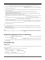
NUDGING THE HIGHLIGHTED PORTION OF A WORKSPACE .................................................................................................107
PLAYING WAVE FILES .....................................................................................................................................................107
Playing a File.............................................................................................................................................................107
Pausing and Resuming Playback ................................................................................................................................108
Playing and Pausing Portions of Wave files using the Right Mouse Button ..................................................................108
Rewinding to Beginning & Fast-Forwarding to End of File.........................................................................................108
QUANTIZING FOR CD AUDIO ...........................................................................................................................................108
PLAYING/EDITING PORTIONS OF A SOURCE OR DESTINATION WAVE FILE ..........................................................................109
6
Diamond Cut Millennium/Live User’s Manual
Playing a portion of your Wave file.............................................................................................................................109
To make a Destination File into the Source File ..........................................................................................................109
PLAYLIST FEATURE.........................................................................................................................................................109
Creating a Playlist......................................................................................................................................................109
Reproducing a Playlist Sequence ................................................................................................................................110
Playlist Export Feature...............................................................................................................................................110
PRINTING HELP-FILE TOPICS ...........................................................................................................................................110
PRINTING A DIAMOND CUT SCREEN.................................................................................................................................110
RECORDING AUDIO SIGNALS ONTO YOUR HARD DRIVE ....................................................................................................111
Recording Procedure..................................................................................................................................................111
System Requirements ..................................................................................................................................................112
Record Transfer to Hard Drive Technical Hints ..........................................................................................................114
REMOVING A LEAD VOCAL FROM A STEREOPHONIC RECORDING ......................................................................................115
RESTORING AN OLD 78 RPM RECORDING .......................................................................................................................116
Clean the Surface of the Recording .............................................................................................................................116
Play the record in a "dry run".....................................................................................................................................117
Clean the Record Surface Once Again ........................................................................................................................117
Set your Pre-amplifier to the Proper Mode..................................................................................................................117
Verify that your Turntable Speed is Correct ................................................................................................................117
Verify that you are Utilizing the Correct Equalization Curve.......................................................................................117
Choose the Best Stylus ................................................................................................................................................118
Fix Record Tracking Problems ...................................................................................................................................119
If it Still Skips, try Half Speed Re-Mastering ...............................................................................................................119
Adjust the Gain and Balance.......................................................................................................................................119
Choose the Appropriate File Conversion Technique....................................................................................................119
Filter out Residual Rumble .........................................................................................................................................120
De-click using the Impulse Filter ................................................................................................................................120
De-Crackle the Recording ..........................................................................................................................................121
De-hiss the Recording ................................................................................................................................................121
Eliminate Line Frequency Hum...................................................................................................................................121
Provide a Fade-In and a Fade-Out Sequence ..............................................................................................................122
Add Your Own Personal Touch to the Transfer ...........................................................................................................122
RESTORING A RECORDED TELEPHONE CONVERSATION ....................................................................................................122
RUMBLE REDUCTION ......................................................................................................................................................123
SELECTIVE FILTERING WITH SYNC MODE ........................................................................................................................124
SIMULATE STEREO FROM A MONOPHONIC SOURCE ..........................................................................................................124
SLIDER CONTROLS OPERATING PROCEDURES ..................................................................................................................124
SPLICING OUT A SECTION OF A WAVE FILE ......................................................................................................................125
Method #1 ..................................................................................................................................................................125
Method #2 ..................................................................................................................................................................125
SPLITTING AND RE-COMBINING STEREO WAVE FILES .......................................................................................................125
TURNING SCREEN-SAVER OFF .........................................................................................................................................126
UNDO PROCEDURE ..........................................................................................................................................................126
USING DC MILLENNIUM/LIVE AS AN AUDIO WAVEFORM ANALYZER ..............................................................................126
Method #1 ..................................................................................................................................................................126
Method #2 ..................................................................................................................................................................127
Method #3 ..................................................................................................................................................................127
Method #4 ..................................................................................................................................................................127
USING THE AUDIO SIGNAL GENERATOR...........................................................................................................................128
ZOOMING-IN & ZOOMING-OUT ON PORTION OF A WAVE FILE ...........................................................................................128
And Now…Some Hardware! ...........................................................................................................................................130
The Owl II..................................................................................................................................................................130
Appendix 1: Glossary of Terms .......................................................................................................................................133
Appendix 2: Language Translations (Deutsch/Español) .................................................................................................162
English.......................................................................................................................................................................162
7
Diamond Cut Millennium/Live User’s Manual
Deutsch......................................................................................................................................................................162
Español......................................................................................................................................................................162
Appendix 3: Preset Listings .............................................................................................................................................166
History..............................................................................................................................................................................173
Diamond Cut Development Timeline ..............................................................................................................................176
License Agreement...........................................................................................................................................................178
LIMITED WARRANTY .................................................................................................................................................180
Diamond Cut Productions Edison Lateral Series CD and Cassette Releases .................................................................181
Additional Restoration Products .....................................................................................................................................182
8
Diamond Cut Millennium/Live User’s Manual
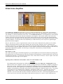
Diamond Cut Audio Restoration Tools Overview
Product Objective: We aim to provide a comprehensive set of tools that will allow the user to remove extraneous noise and
also enhance the sound contained on old audio sources without degrading the content contained on the original. Recognizing
that there is a tradeoff between the degree of noise removed from a source and the fidelity, transient and frequency response
maintained, we have sought to provide the highest level of user control while maintaining ease of use over the variables which
effect the Audio Restoration Process.
Diamond Cut Millennium introduces a “Multi-filter” and Diamond Cut LIVE additionally introduces (feed-through) mode
into its feature set. Both products include 4 new powerful Forensics filters. The “Multi-filter” allows you to cascade at least
24 filters or effects. The “Live” (feed-through) mode allows systems with full duplex capability to bypass the system hard
drive, and use the computer as a “Live” signal processor. In other words, the signal is applied to your computer’s audio input,
is processed by the Diamond Cut algorithms, and then is presented to its output a few hundred milliseconds later. A
tremendous amount of versatility and flexibility has been added, particularly when “Live” is used in conjunction with the
“Multi-filter.” Additional new and innovative features that have been incorporated into both versions of Diamond Cut include
the following:
1.
2.
3.
4.
5.
6.
7.
8.
9.
10.
11.
12.
13.
14.
15.
16.
17.
18.
19.
20.
21.
22.
23.
8 to 24 bit support at up to 48 kHz sampling rate
Sample rate conversions
Variable resolution added to the Continuous Noise Filter
Audio Spectrum Enhancer added to the Dynamic Noise
Filter
Batch File Editor
Slot Filter for isolating sounds in Forensics applications.
Stereo wave file 180-degree phase-inversion
X-Y output display for plotting vector waveforms
Stereo Channel Blender / Crossover Filter & Effect
Speed Enhanced Display Functions (especially on large wave files)
Improved Reverb
Printable 50/60 Hz Turntable Stroboscope discs
Additional factory presets
Additional Keyboard Accelerators
Variable Resolution Spectrum Analyzer
LIVE Log to Disk Mode
Automatic Level Control
Output VU Meters
New Tubes added
Upgraded Spectrum Analyzer
Punch and Crunch Four Band Dynamic Expander/Compressor
Triangle Wave Generator
Diamond Cut Productions, Inc. designed Diamond Cut Audio Restoration Tools primarily to be used for the restoration of
olde phonograph recordings. These recordings often contain priceless performances which are marred by the effects of age,
wear, and the limitations of the media on which they were originally recorded. DC Millennium/LIVE is effective for
"cleaning up" old cylinder recordings, hill and dale Edison Diamond Discs (verticals), old 78's (laterals) (both acoustically and
electrically mastered), and of course, modern vinyl LP's and 45 rpm records. However, the program can also be used for
additional sound restoration, special effects, or professional applications such as:
1.
2.
3.
4.
5.
Single Ended noise reduction of old analog tape recordings.
Cleaning up old optical and magnetic movie soundtracks.
Improving the intelligibility of surveillance recordings.
Improving the intelligibility of recorded telephone conversations.
Applying certain special effects or equalizations to any sound recording.
9
Diamond Cut Millennium/Live User’s Manual
6.
7.
8.
9.
10.
11.
12.
13.
Removing static and noise from radio broadcasts, most particularly from signals carried on the AM and Short Wave
Bands.
Providing a graphical means for analyzing the noise content of audio recordings.
Selective manual modification of recording waveforms.
Providing special audio effects for movie, radio, television or stage theatrical use.
General-purpose audio applications in Forensics laboratories.
Use as an instructional aid for the teaching of the applied principles of Digital Signal Processing.
Cleaning up and enhancing video tape soundtracks.
Personal enjoyment and entertainment.
This program has thus far been used on eight of Diamond Cut Productions compact disc releases of historical musical
material. Its performance can be auditioned on the following Diamond Cut Productions CD’s:
•
•
•
•
•
•
•
•
•
•
Unreleased Edison Laterals I
The California Ramblers - - - Edison Laterals 2
Hot Dance of the Roaring 20's - - - Edison Laterals 3
Eva Taylor with Clarence Williams - - - Edison Laterals 4
Vaughn De Leath, The Original Radio Girl, Edison Laterals 5
B.A. Rolfe and his Lucky Strike Orchestra, Edison Laterals 6
Hot & Rare - - - Hot Tunes from Rare Bands and Recordings
The Marvelous Melodies of Peter Mendoza
Edison Diamond Disc Fox Trots: 1920 - 1923
Rudy Vallee and His Connecticut Yankees: 1928 - 1930
Other labels such as the Smithsonian Collection of Recordings have used this program to clean up several songs on their
"American Songbook Series". And County Records used Diamond Cut to produce their release entitled "Ernest Stoneman
and his Dixie Mountaineers". It was written by two engineers in their spare time to facilitate the very specific needs that
arose in their restoration of the Edison Lateral Collection of Test Pressing Recordings, which is located at the Edison National
Historic Site in West Orange, New Jersey. Rick Carlson and Craig Maier developed this program over a four-year period.
They have now made it available to the general public with the idea in mind that if it solved some audio restoration problems
for themselves, it might also be of use to others confronted with similar problems, particularly for those operating with
significant budgetary constraints.
Here is a list of the functions that DC Millennium/LIVE can perform:
1.
2.
3.
4.
5.
6.
Record Audio signals onto your computer’s hard drive.
Playback Audio signals from your computer’s hard drive.
Display the Amplitude vs. time waveforms that represent your wave file.
Zoom-In and view details of a particular portion of your wave file.
Print the electrical waveform representation of your wave file.
Perform the following group of non-destructive editing on your wave file including:
A. Remove Impulse Noise from a recording including "ticks", "clicks", and "pops."
B. Remove "Crackle" from a recording utilizing a Median Filter.
C. Remove Continuous Noise from an audio signal.
D. Display the frequency domain content of a selected portion of a wave file.
E. Perform a Low Pass Filter function with 1st, 2nd or 3rd order slopes.
F. Perform a Band Pass Filter function with a Finite Impulse Response (FIR) and an Infinite Impulse Response (IIR)
algorithm.
G. Perform a High Pass Filter function with 1st, 2nd or 3rd order slopes.
H. Perform a Dynamic Filter function to reduce "Hiss" from an audio signal.
I. Perform various file conversions such as left plus right, left minus right, etc.
J. Perform an Average filter function.
K. Attenuate Hum or Acoustical Feedback from a recording.
L. Manually interpolate noise events out of your wave file.
10
Diamond Cut Millennium/Live User’s Manual
M. Frequency Equalize your recordings to create a more pleasing tonal balance with the built-in 10-band Graphic
Equalizer.
N. Correct the pitch of a recording with the “Change Speed” Filter, with linear or non-linear time contours.
O. Perform fractional speed remastering from a 45-RPM turntable, and then convert it to normal speed with the “Change
Speed” Filter.
P. Create a wave file “Songlist” with Markers capable of CD data Quantization for glitchless indexing.
Q. Attenuate Buzz from a recording using the Harmonic Reject Filter.
R. Add “tube-warmth” or harmonic enhancer effects
S. Modify the dynamic range of recording
T. Set up a “noise-gate” function
U. De-ess an overly sibilant recording
V. Create or reverse an RIAA equalization curve with the 10 band Paragraphic equalizer. Also, create various 78-RPM
turnover equalization curves.
7.
Perform the following group of destructive editing on your wave file including:
A. Fade in sequence with either a linear or a logarithmic envelope vs. time.
B. Fade out sequence with either a linear or a logarithmic envelope vs. time.
C. Crossfade between two wave file sources with linear or logarithmic timing.
D. Mute a portion of your wave file. This is useful for ridding a file of stubborn "pops" or "thuds."
E. "Gain Ride" to even out variations in the sound level of a recording in non-real time.
Edit Wave files using any of the following commands:
1) Copy
2) Paste Over
3) Paste Insert
4) Cut
5) Interpolate
F. Undo any of the destructive editing that you have performed with any number of levels of the undo function that you
choose to define.
8.
Analyze Audio signals for Amplitude and Frequency content utilizing any of three possible methods, including the use of
a "built-in" spectrum analyzer.
Measure the performance of the electronic components in your audio restoration laboratory with a built-in Audio Signal
Generator that is capable of producing Sine and Square Wave signals (tones) of adjustable frequency and amplitude. It is
also capable of producing white and pink noise using the Random function. Also included is a burst and linear sweep
generator function.
Real time "Preview" of all filter functions for instant evaluation of parametric settings.
Hear the noise being removed by two of the filters through a “Keep Residue” mode.
Add reverb to “dead” recordings.
Create a Stereo Effect on monophonic recordings.
9.
10.
11.
12.
13.
When Diamond Cut Productions introduced its 32-bit version of the program in 1998, we not only added new audio
restoration features, but included some audio enhancement capability as well. Some of the features added at that time
included:
1. A Virtual Valve Amplifier to produce “Tube Warmth.”
2. A Harmonic Exciter for synthesizing missing upper octaves.
3. A Dynamics Processor that includes an expander/gate, compressor, and de-esser.
4. A “Paragraphic” Equalizer, which is an innovative 10-band parametric equalizer with a dual-function graphical display.
5. A real time peak or averaging Spectrum Analyzer, and bar graph amplitude display.
6. Instant bypass mode.
7. Looping of Playback and Previews.
8. Filter and effects factory pre-sets.
9. On-the-fly changes between factory and user pre-sets when in preview mode.
10. A “Find and Mark Silent Passages” detector is provided, to automatically break a wave file into pieces based on silent
sections.
11. Built-in Forward and Reverse RIAA curves, and 78-RPM turnovers.
11
Diamond Cut Millennium/Live User’s Manual
12. Time-Offset for correcting tape Azimuth problems, improving intelligibility, and creating a stereophonic effect from a
monophonic source.
13. Random noise generators (white and pink noise.)
14. A normalize gain function.
15. Over 230 factory presets.
16. A playlist export feature
It is important to emphasize that DC Millennium/LIVE performs most of its editing in a non-destructive manner. The source
file remains non-modified; only the destination file receives the modifications. Not all wave file-editing programs work in this
manner, and some actually modify the source file directly on your hard drive.
It will take some experience to achieve excellent results from the software so don't be afraid to experiment. The preview
feature will allow you to quickly hear the results of parameter setting changes before you commit your computer resources to
the job of a complete file processing. Some PCs are not fast enough to run all of the algorithms in real time, so you may find
yourself making use of the preview function often. The minimum system configuration that we recommend that you use to
run Diamond Cut 32 is a 100 MHz Pentium. A 166 MHz Pentium or higher will generally run most Diamond Cut algorithms
in real time or faster in non-preview mode, and for “Run” mode performance, faster is always better. If you are using “Live”
you will want the fastest computer that you can afford for maximum functionality, performance and versatility.
Most sound restoration jobs will take several passes with different algorithms applied to achieve the best results. Since many
of these algorithms are non-linear systems, the order in which some of the various filters are applied will matter. You will find
more on this topic in the Impulse Filter section of the Help file.
Note 1: DC Millennium/LIVE utilizes the Wave file format for its file system. Other sound file formats are not supported at
this time.
Note 2: Most of the algorithms used in DC Millennium/LIVE use double precision floating point math as opposed to fixed
precision integer math in order to minimize the possibility of introducing digital noise and artifacts into your wave files. The
tradeoff associated with using this method is the time required to process a file being somewhat longer than the fixed precision
integer method.
12
Diamond Cut Millennium/Live User’s Manual
Getting Started with DC Millennium/LIVE
Installation
Congratulations, you’ve just purchased another affordable yet powerful Enhancedaudio.com branded product. You have
our promise that you’ll be satisfied with your results without having to take a second mortgage to get them!
NOTE: Be sure to return the registration card to Enhancedaudio.com Inc. to ensure support, upgrade and bug fix notification.
To install the software please follow these steps:
Windows 95, 98, 2K and NT Instructions
1.
2.
3.
4.
5.
Put the install CD into your drive. If Autorun is enabled, installation will begin immediately. If not:
Press the Start button, choose Run from the pop-up menu
Type in the letter of your CD Rom drive
Press the OK button
The Diamond Cut install program will start. Follow the instructions on the screen.
The software will be installed in a folder called Diamond Cut Productions. A sample wave file is supplied called
DEMO1.WAV.
The Users Manual and Audio Restoration Tutorial are part of the standard Windows help system available from the help
menu.
Configuration
DC Millennium/LIVE does not require any special installation, but it does require that your sound card be installed and
working properly. If you have more than one sound card in your system, make sure the one you wish to use has been selected
in the Device I/O screen (use the Edit->Device I/O menu). Check the Temp File Path under the Edit->Preferences menu. DC
Millennium/LIVE automatically assigns temporary file names for files that are being processed. You should set the temporary
drive path for the disk drive that you wish to use for audio editing. This is usually the drive with the most free disk space.
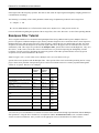
Keep in mind that high quality (44.1kHz) stereo recording consumes 10.5MB of disk space per minute.
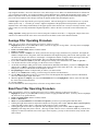
Basic operating mode of DC Millennium/LIVE
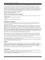
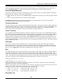
DC Millennium/LIVE always operates in a non-destructive manner. When a file is processed with a DC Millennium/LIVE
filter or effect, the software reads the source file, modifies it with the selected filter or effect, then writes it to the destination
file. The main workspace of DC Millennium/LIVE always has a source and a destination file. This mode of operation has a
few important benefits:
1. The original source file is not modified, leaving it available for instant comparisons with the processed version.
2. The original material can always be recovered if the results of processing are unsatisfactory.
3. Selected sections of the file can be reprocessed using different filter parameters or different filters entirely (see sync
mode).
Because of the non-destructive nature of the filters in DC Millennium/LIVE, there is no undo function for the filters. Instead,
the original source can be copied back to the destination file if a mistake is made. This method greatly speeds up the program
because it does not have to make a copy of the data each time a filter is run.
There is an undo function available for all of the single file commands such as Cut and Paste. These are explained later.
13
Diamond Cut Millennium/Live User’s Manual
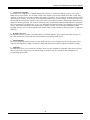
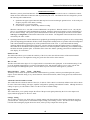
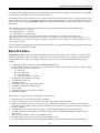
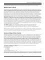
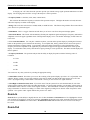
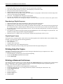
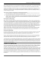
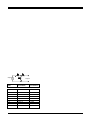
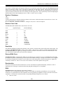
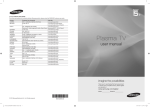
The following diagram illustrates the filtering process:
Original Source material
Source file
DCart Filter
Destination file
Final media
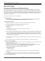
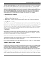
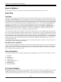
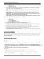
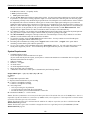
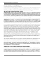
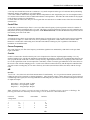
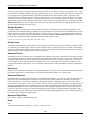
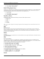
Sync Mode
Sync mode is the default mode of operation for DC Millennium/LIVE. In Sync mode, both the source and destination files
track each other. If you zoom into a section of the source file, the destination file will zoom to the same section. When you
process the source file using a DC Millennium/LIVE filter, the program reads the source file, processes it, and writes it to the
destination file at exactly the same position as the source file. This means that if you want to reprocess a section in the middle
of a song, just highlight the section in the source file that needs processing and run the filter again.
The filtered section will be written to the correct location in the destination file. This mode of operation is useful for changing
the filter parameters for only a section of a song, or for removing noise from a small section of the song without having to
process the entire file.
Note: Sync mode assumes that a destination file exists, and that it is the same size as the original file. This is usually
accomplished through the application of one of the Diamond Cut filters to the entire file. For example, the file conversion
filter can be used to make the destination file into an exact copy of the source file.
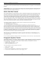
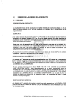
Source file
DCart Filter
Destination file
Sync Mode Operation
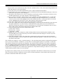
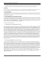
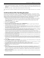
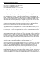
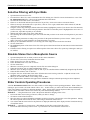
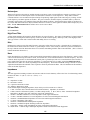
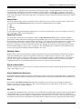
Non-Sync mode of operation
14
Diamond Cut Millennium/Live User’s Manual
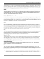
In non-sync mode, the highlighted section of the source file is read and processed by the DC Millennium/LIVE filter. The
processed section is then written to the destination file, starting at the beginning of the file. If a destination file already exists,
it will be overwritten (a prompt warns you of this). This mode is useful when only a section of the source file needs to be
extracted, or for testing a filter’s settings before processing an entire file.
Source file
DCart Filter
Destination file
Non-sync mode operation
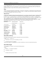
Single file operations
Because of the nature of several operations, the Cut, Copy, Paste, and Fade menu items operate on the file that is currently
selected. This means that a Cut will delete a section of the source file if it is the currently selected file in the workspace.
Likewise, a Fade operation will modify the highlighted section of the selected file (Source or Destination).
All single file operations can be undone by using the Undo menu item. The default number of undo levels is 10. The number
of undo levels is selectable in the Preferences dialog box. The maximum number of undo levels is limited to 100. When you
close DC Millennium/LIVE (Exit the program) all undo information will be lost.
Preview Mode
All the filters in DC Millennium/LIVE have a preview mode. Preview mode lets you hear the result of a filter before writing
the changes to the Destination file. In Preview mode, you will hear the results of the filtered file as it is being processed. If
your computer is fast enough to keep up with the calculations, the entire file can be previewed in this manner. All of the filters
have live controls, which means that adjustments made to a filter’s slide control will be immediately heard in the preview
output.
If your computer cannot keep up with the calculations, you will hear stuttering in the preview output. This is because the
playback is being paused while the computer calculates the next section of music. This stuttering can be minimized by
increasing the number of ”Preview Buffers” in the Preferences Dialog box (Edit->Preferences).
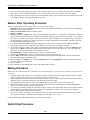
Restoring a Recording
While there are many ways to use DC Millennium/LIVE, the general steps are outlined below. Keep in mind that any of the
filters may be skipped if the particular recording does not suffer from the kind of noise the filter is designed for. You should
always use the least amount of processing that will get the job done. See the section on Filters for a brief description of each
filter’s function. The tutorial on restoring the Demo wave file later in this booklet describes some of these steps in detail.
1. Record the source material
The source material is recorded from an external source into a wave file using the Record function of DC
Millennium/LIVE.
2. De-Click
The Impulse noise filter is used to remove ticks, pops, and other transient noises from the recording.
3. DeHiss
You can use either the Continuous Noise filter or the Dynamic noise filter to remove constant background hiss or other
wideband noise from a recording. This type of noise is the most difficult to remove without effecting the music.
15
Diamond Cut Millennium/Live User’s Manual
4. Filter (HP, LP, Notch, Harmonic Reject, Equalizer)
The High Pass, Low Pass, Notch, Harmonic Reject, and Equalizer are all filters that modify the frequency response of the
recording.
Some examples are:
• High Pass filter for removing rumble
• Notch or Harmonic Reject filter for removing hums, buzzes or feedback.
• Equalizer for adding bass or emphasizing the vocal range.
This step may be performed before the continuous noise filter to remove rumble or high frequency noise. See the help file
for additional examples of which filter to use for a particular problem.
5. Trim, Fade-in/Fade-out
After the processing is done and you are satisfied with the results, you can use the Cut, Fade-in and Fade-out functions to
remove any noise that occurs before and after the recording, such as the sound of the record needle being dropped on the
lead-in groove. Keep in mind that the Cut and Fade functions operate on the selected file. This means that, unlike the
filters, you can modify the source file if you want to.
6. Transfer to final format (CD, Cassette, DAT)
After the restoration process has been completed the file should be transferred to a portable format such as CD, cassette or
DAT. To transfer to cassette or DAT, simply set up the cassette or DAT machine to record from the computers sound card
and play the wave file. If you are restoring an entire album or want to create a master tape, use the Playlist feature.
This allows you to create a list of wave files and play them back in sequence, thus eliminating the time consuming steps
of starting and stopping the recorder between each song.
CD recorders usually have special software that must be used to record the file onto the CD. DC Millennium/LIVE has a
CD quantization feature that lets you perform special processing to ensure glitch free CD masters.
Filters and Effects
The filters are at the heart of the operation of DC Millennium/LIVE. They are used to reshape the sound from its original
form into a more pleasing and noise-free result. The following section lists all of the filters available in DC Millennium/LIVE
along with a description of the type of filtering they perform. The help file contains a table of various sound source defects and
the type of filter to use for each one (search for help on ”Filter Applications”).
• Impulse Noise Filter
This filter is used to remove pops, ticks, clicks, and crackle from audio recordings. It is also useful for the elimination of
”static” interference from AM or Short Wave radio broadcasts. An Impulse looks like a spike or fast change in the audio
signal that is not related to the music. The filter monitors the audio signal for ticks or pops and replaces them with an
approximation of the signal that would have occurred during the tick or pop.
•
Continuous Noise Filter
This filter is useful for reducing background ”Hiss” and other constant noise from a recording or from a noisy FM
radio transmission. It is referred to as a ”Continuous” noise filter because unlike Impulse noise, Hiss is present at all
times. When adjusted properly, this filter can almost completely eliminate all residual noise from a recording.
However, it is easy to overuse this filter and leave the recording sounding dead and lifeless, and also introduce digital
artifacts into the music.
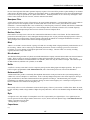
To use this filter, you must first take a sample of a section of noise. This noise template will then be used to decide
what is noise and what is music during the filtering process. It is important to sample a section of the wave file that
does not contain any music so that the filter does not remove signals that contain musical information.
16
Diamond Cut Millennium/Live User’s Manual
The filter graphically shows a frequency spectrum of the sampled noise. This spectrum represents the amount of
noise at each frequency band in the recording. You can use the mouse to move the blue threshold line to tailor the
kind of noise reduction that the filter performs.
This filter should only be used on recordings that have little or no impulse noise, or on recordings which have already
been processed through the Impulse Noise filter.
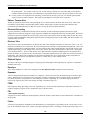
•
Harmonic Reject Filter
The Harmonic Reject filter is used to remove harmonically rich noise from a recording. Noises such as hums and
buzzes from electrical mains, or buzzes from broadcast signals are the most common types. A loose or bad ground
connection on a turntable is a common cause of hum that can be removed with this filter.
The filter removes the fundamental frequency along with a selectable number of harmonics. Harmonics are multiples of
the fundamental frequency that are present in all signals that are not a sine wave. For the US, a hum caused by a faulty
ground will have a fundamental frequency of 60Hz, (50Hz in Europe).
•
Dynamic Noise Filter
This filter is another form of the ”Continuous noise” filter, but it operates on a different principle than the previous filter.
It is also useful for removing ”Hiss” from recordings, but unlike the ”Continuous Noise Filter,” will not introduce any
digital artifacts into the recording. It is much more forgiving of incorrect settings at the expense of less overall hiss
reduction.
The Dynamic Noise filter can also be placed in another mode of operation producing a spectral enhancer. Signals above
the threshold value will be incrementally amplified in this mode.
The Dynamic Noise filter’s operation is based on a moveable Low Pass filter. This low pass filter will attenuate the high
frequency Hiss only when there are no high frequency signals present in the music. This filter should also only be used on
recordings that have no impulse noise.
• Low Pass Filter
This filter is called a Low Pass filter because it only passes through signals that are lower than its set corner frequency. It
attenuates high frequency signals above the corner frequency.
The effect can be similar to turning down the treble control on a home stereo except that the Low Pass filter is much
more flexible. This filter can be somewhat useful for reducing hiss in a recording, but care must be taken not to
reduce the “presence” of a recording by eliminating too much of the high end musical content at the same time.
It is most useful where a recording does not contain any musical information above a certain frequency, and you wish
to eliminate the high frequency noise that would otherwise be present.
•
Band Pass Filter
Band Pass filters are essentially a combination of a low pass filter and a high pass filter. It attenuates both the high
frequency and the low frequency portions of the audio spectrum. It is useful where the recording contains extraneous
noise in the low frequency region such as rumble or thumps, and high frequency noise such as hiss.
This filter can also be very useful for improving the intelligibility of audio recordings, especially speech, by
eliminating the unnecessary portion of the audio spectrum that is not used by speech frequencies to carry useful
information to the listener.
• High Pass Filter
A high pass filter only passes signals that are above or ”higher” than the corner frequency. It reduces the level of low
frequency signals that are below the corner frequency. The effect can be similar to turning down the bass control on a
home stereo. This filter is very useful for reducing turntable rumble, muddiness, and any other extraneous low frequency
noise in a recording.
17
Diamond Cut Millennium/Live User’s Manual
• Notch Filter
A notch filter attenuates signals that are near its center frequency setting. The degree to which it attenuates frequencies
near the center frequency is determined by the bandwidth setting. This filter is useful for removing 50 or 60 Hz hums
from a recording. It is also useful for decreasing any sound system acoustic feedback that may be found on some live
recordings. A “Slot” filter is also provided within the Notch filter menu item for Forensics applications. Multiple slots
can be constructed using the DC Millennium/LIVE Multi-filter.
• Median Filter
The Median Filter can be used to substantially reduce ”crackle” (small impulse noise) from a recording. Use a sample
setting of 3 to 7 for this application. Also this filter is useful for improving the intelligibility of severely distorted signals
and pulling signals out of a very poor signal-to-noise ratio situation (pulling signals out of the mud). It is somewhat
similar in sound performance to a high-order low pass filter.
• Average Filter
This filter sounds similar to that of a low pass filter, although it is somewhat more effective than a low pass filter in
reducing not only ”Hiss” but also ”Crackle” from a sound source. It is most effective on limited bandwidth sources such
as old acoustic recordings made before 1925. This filter is also useful for improving the intelligibility of highly garbled
voice communications recordings.
• Equalizer
The equalizer is a familiar filter that acts like an expanded tone control. The audio spectrum is broken into 10 bands, each
being one octave wide. Each band’s gain (volume) can be independently adjusted to achieve the desired audio result. This
filter is useful for tonal shaping of the finished audio product or to enhance the bass or treble of a recording. It is also
useful for improving the intelligibility of recordings or ”Bringing Out” a particular instrument or vocal.
• File Conversions
The File Conversion filter is not really a filter at all but a way to convert mono files to stereo and visa-versa. It can also be
used to adjust the channel balance or reverse the channels of a stereo recording, or convert a mono source into a stereo
file. It is useful in converting stereo recordings made out of phase (such as old vertically recorded acoustic discs) into a
stereo or mono file that is compatible with modern systems. File Conversions also includes two controls. One set allows
you to adjust the gain levels for each channel. The second control, called Time-Offset, provides a means for azimuth
correction, Forensics audio enhancement, and stereo simulation. A final important use of the file conversion filter is to
simply copy parts of the source file over the destination file. This is one way to revert back to the original source file
(undo) following a bad filter application.
• Crossfade
The Crossfade filter is used to join sections of different wave files into a single wave file. Rather than just abruptly ending
one file and starting another, the Crossfade filter will smoothly fade from one file to another. During the time that the files
overlap, the destination file is gradually faded to silence, while the source file fades from silence to full volume. This filter
is also available from the edit menu as a paste function.
• Change Speed
The change speed filter is used for either fractional speed mastering or for correcting the pitch of an off-speed recording.
If your record skips when played at normal speed, consider playing it at a slower speed and use the change speed filter to
restore the original pitch. If your recording is off-pitch, or contains momentary pitch deviations, use the graphical pitch
vs. time contour graph to correct these deviations.
• Reverb
The Reverb effect is used to add a realistic room sound to a recording. The reverb is capable of simulating different size
rooms, with different kinds of reflective surfaces and decay times. The reverb filter lets you control the overall room size,
decay time, early reflection level, and mix between the original material and reverb sound. Unlike most of the other filters
in DC Millennium/LIVE, the Reverb filter is really an effect, rather than a restoration tool.
18
Diamond Cut Millennium/Live User’s Manual
• Virtual Valve Amplifier
The Virtual-Valve Amplifier is a computer simulation of a number of vacuum tube amplifier circuits. (Valve is the
British term for electron tube. We call it the “Virtual Valve Amplifier, because that sounds cooler than “Virtual Tube
Amplifier.”) Its effect is to add “tube-warmth” to the sound of a recording. This is sometimes desirable to apply to DDD
(purely digital) recordings. It can also be used to add subtle harmonics to very old recordings. A harmonic exciter is also
included with the Virtual Valve Amplifier. This feature allows you to choose the mixture and harmonic distribution to be
added back into the signal path. It is useful for enhancing vocals, and simulating additional bandwidth on recordings that
have lost signal due to generational loss, or age. It is important to note that the Virtual Valve amplifier is using real tube
circuits, and real tube non-linear device characteristics to produce its effect. The wide range of adjustability of this
algorithm will allow you to create an amplifier that runs the gamut in sonic performance from “grit-guitar” to “high-end
audiophile.”
• Dynamics Processor
The dynamics processor provides you with the ability to control the dynamic signal content of the audio envelope of a
wave file. Included are compression, downward expansion, noise gating, and de-essing.
• Channel Blender
The channel blender provides the ability to reduce muddy bass from vinyl recordings, decrease the “ping-pong” effect
from early Stereophonic recordings, and minimize Multi-path distortion from FM stereophonic broadcast recordings.
• Multi-filter
The Multi-filter allows you to cascade up to 24 filters, and to save the combinations’ parametric values under one preset
name for easy recall. This provides you with the ability to construct your own customized filter combinations for
accomplishing specific tasks.
19
Diamond Cut Millennium/Live User’s Manual
Demo File Tutorial
Restoring the DC Millennium/LIVE Demo Wave file
The following is a description of a ”basic” procedure that will restore the DC Millennium/LIVE Demo Audio Wave file,
including settings that will give reasonable (not optimal) results. Its intention is to step you through an audio restoration
process in order to familiarize you with some of DC Millennium/LIVE’s features. The song segment you will be restoring is
titled ”My Sin” (matrix # N-869G) which was performed by the California Ramblers for the Edison Company on 4-25-29. It
can be heard in its complete and restored form on a Diamond Cut Productions release entitled ”The California Ramblers - - Edison laterals 2” (DCP-301D).
It is important to note that the steps are order dependent.
1. Open the Wave file:
1.1 Open the DC Millennium/LIVE demo wave file by using the File, Open Source menu, and select the file called
Demo1.wav. This file is in the \DCMILL\wave file or \DCLIVE\wave file subdirectory.
2. Remove the Ticks and Pops:
The Impulse Noise Filter will be used to remove the ticks, clicks and pops from the Demo Wave file.
2.1 Click on the Impulse Noise Filter that can be found under the Filter Menu.
2.2 Set the Impulse Filter Parameters to the following values:
A. Threshold = 9900
B. Size = 6
C. Tracking = 1
D. Vinyl LP mode is not checked (in other words, this feature is not enabled)
E. Preview Mode is not checked
2.3 Click on ”Run Filter” using the left mouse button. The computer will start processing the file, and depending on the
speed of your computer, will have completed the file after somewhere between 5 to 60 seconds. At the end of this
process, you should note that the statistics dialog box will have indicated that roughly 350 clicks have been removed
from the Source File. This step will have completed the De-Clicking process. The results of this process will be the
file found in the Destination Workspace.
2.4 To hear the results of this process, press the play button on the toolbar (the arrow pointing toward the left). Note: this
step is optional.
2.5 Shut down the Impulse Filter by clicking the Close button on the dialog box, using the left mouse button.
3. Remove Low Frequency Rumble:
The next procedure is intended to remove low frequency ”rumble” from the Demo Wave file. You will be using the DC
Millennium/LIVE High Pass filter.
3.1 Click on the ”Make Destination the Source” function that will be found under the ”File Menu.”
3.2 Next, click ”OK” in the ”Save As” dialog box. DC Millennium/LIVE will automatically assign a Temporary File
name to this new Source file. It can be viewed in the newly opened ”Source Workspace.”
3.3 Click on the High Pass filter that will be found under the Filter Menu.
3.4 Set the following Parameters:
Frequency = 55 Hz
Slope = 18 dB / Octave
3.5 Click on ”Run Filter.” After the filter has completed its operation, the results will be found in the Destination
Workspace.
3.6 To hear the results of this process, once again, click on the play button. You should hear that the rumble on the
original recording is now gone. Your speakers must have good low frequency response to hear the difference.
4. Remove the Hiss and surface noise:
20
Diamond Cut Millennium/Live User’s Manual
This procedure uses the continuous noise filter. The term ”Continuous Noise” refers to the constant background hiss and
crackle that appears on most old recordings.
4.1 Once again, click on the ”Make Destination the Source” feature found under the File Menu.
4.2 Click on ”OK” in the ”Save As” dialog box. The file, which had just been in the Destination Workspace, will now be
found in the newly opened ”Source Workspace.”
4.3 The purpose of the next process is to remove continuous noise from the recording. This includes such noises as hiss
and other random noises. You will be using the ”Continuous Noise Filter.”
4.4 First, you must give the filter a sample of noise to use as a template. To do this, highlight the first ½ second of the
Demo Wave file. To do this, use the left mouse button and drag it until approximately the first 0.5 seconds of the
source wave file is selected. The highlighted sector will be indicated in yellow. Use the play button to be sure that
you have highlighted only lead-in groove noise, and no impulses from stylus drop or music.
4.5 Click on the Continuous Noise Filter, which will be found under the Filter Menu.
4.6 Click on the ”Sample Noise” button found in the filter dialog box. You will see a blue threshold line appear above the
red signal spectrum line. It is only necessary to understand what is going on here if you are an advanced user.
Otherwise just follow the directions. If you are an advanced user, you will find more information on the use of this
filter in other sections of the Help file discussing the Continuous Noise Filter.
4.7 Set the following parameters for the Continuous Noise Filter:
A. Attack Time = 40 msec.
B. Release Time = 80 msec.
C. Attenuation = 100dB
4.8 Highlight the entire source workspace by double clicking with the left mouse button anywhere within the source
waveform display area. It may be necessary to move the Continuous Noise filter dialog box out of the way before
selecting the source waveform.
4.9 Click on the ”Run Filter” button. The results of the Continuous Noise Filter processing step will be found in the
Destination Workspace, after your computer has completed running the algorithm. To hear the results, click on the
play button on the toolbar.
This concludes our example of a ”basic” sound restoration job. The next advancement would be to adjust the filter parameters
more to your own personal taste. Furthermore, you may choose to run the graphic equalizer, low pass filter, or some other
filter after the continuous noise filter has been completed. The variations in the results that you can obtain are tremendous
when you consider all of the various permutations of filters and parameters available for you to choose from. Proficiency in
the use of DC Millennium/LIVE will develop over time as you experience the various results that can be obtained from the
program. Refer to the help file section entitled ”Filter Applications” to help determine what type of filter to use for the various
sound restoration problems which you are encountering.
By using the “Save Settings” feature you can save the ranges of parametric values that have worked well for you for certain
filters as a function of the type of materials you have restored. But most importantly, become familiar with all of the filter
procedures and tutorials found in this Users Guide.
21
Diamond Cut Millennium/Live User’s Manual
Common Questions
This section lists some common questions new users have about DC Millennium/LIVE.
Q Why does the waveform display only show part of my file?
A By default, DC Millennium/LIVE only reads the first few megabytes of a wave file for the initial display. This
adversely affects none of the wave file processing operations. Portions not shown on the display can still be played, filtered
and operated on just as if they were displayed. To set the size of the waveform that will be displayed, use the Preferences
dialog box (under the edit menu) and increase the ”Display Length Limit” to the size of the file you wish to be displayed.
Keep in mind that the larger the display size, the longer it will take to initially open a wave file.
Q How do I control the recording level of the audio signal?
A In Windows 95, there is a speaker Icon in the lower right hand corner of the Taskbar. Double-click on this Icon to bring
up the control panel for your sound card. There are level controls for the Mic or Line inputs of the sound card. Also be sure
that the correct input is selected (Mic, Line, or Aux) for your particular recording setup. For Windows 3.11 systems you
should either use the mixer application that is supplied with your sound card or use the Windows control panel to access the
sound card driver utilities.
Q Why does preview mode sound like it is stuttering?
A All of the filters in DC Millennium/LIVE require a fair amount of processing power. If your computer cannot complete
the processing fast enough to keep up with the audio stream, then the preview mode will stop and start in short bursts that
sound like stuttering. This effect can be reduced or eliminated by increasing the number of ”Preview Buffers” in the
Preferences dialog box. Each “Preview Buffer” adds about 10ms of pre-processing before preview playback starts. So
increasing the Preview buffers to 50 will give approximately 5 seconds of clean (non-stuttering) audio.
Q Will increasing the amount of RAM in my computer make DC Millennium/LIVE run faster?
A DC Millennium/LIVE does not require huge amounts of RAM. If your computer system has 12 to 16 Mbytes of RAM,
then further increases will not appreciably speed up the program. The software uses disk based processing so hard drive speed
and raw processor speed will generally have a greater effect than increased RAM beyond a certain minimum.
Q Will a Pentium Processor with MMX speed up the program?
A No. While a faster clock speed is better regardless of the processor, the MMX feature of all new Pentiums is designed to
speed up Fixed-point operations. DC Millennium/LIVE performs all of its processing using floating-point calculations that are
not affected by MMX.
Q I want to purchase a system optimized for use with the software. What sort of system will provide me with the fastest
performance of all of the various DC Millennium/LIVE filters, effects, and editing features?
A Purchase a computer with the fastest clock speed possible. Check benchmark performance of the CPU chips math coprocessor performance, and specify the one that produces the best results. Keep DC Millennium/LIVE on a different hard
drive from your wave files. And use SCSI hard drives as opposed IDE drives. Look for drives with fast access times.
Purchase a high performance sound card. Lastly, turn off all superfluous programs that may be running in background.
22
Diamond Cut Millennium/Live User’s Manual
Q I am unable to record a wave file using the DC Millennium/LIVE program. What can I do?
A If you press the record button and the recording level meters do not move, check the following items:
1.
2.
3.
Make sure that your music source (CD, tape player, DAT, etc) is connected to the correct input on your sound card. This
should most likely be the LINE or AUX input.
Go to the control panel, and click on the Multimedia Icon. Make sure that the correct audio card is selected as the
recording device and that the recording level is not set to zero.
Most sound cards place a volume control on the task bar. Click on the volume control icon to bring up the level control
screen. Select the recording controls (usually a menu item.) Make sure that the input is enabled. Sometimes the LINE or
AUX inputs are disabled by default.
Q How do I avoid producing dropouts during recording or playback?
A Make sure that you have reviewed all of the following:
1.
2.
3.
4.
5.
Make sure that you are using the latest drivers for your sound card. They can usually be obtained from the card
manufacturers or Microsoft’s web site.
Make sure that the screen saver and all power management functions will not kick-in during recording or playback. By
default, the screen saver has a 1-minute timeout, so after 1 minute of no keyboard or mouse activity, the screen saver will
kick-in. This flurry of disc activity will put a glitch on the recording or playback of wave files.
Turn off all power saving features, or set their timers to a value of time greater than the longest musical selection that you
want to record or play.
Make sure that there is nothing in the Start-Up group. Look in the Windows Start->Programs->Startup group and
remove any programs that may run during your recording session. A notorious culprit is Microsoft’s Fast-Find feature. It
periodically searches the hard disk. It is installed with all Microsoft Office products.
If you are getting desperate, try disabling virtual memory in the Windows control panel. Novice users should not attempt
this because it can seriously affect your PC’s performance.
Q I have a vinyl LP that is very noisy, and still has too many clicks after processing. What can I do?
A Try running the impulse filter twice or more. First run it with the Tracking control set to zero, and adjust the threshold
control to remove just the largest clicks. When done, make the destination the source, and re-run the filter with the Threshold
set back to 1, and adjust the tracking control to get the smaller clicks.
Another thing to try is to use the file reverse feature, and then process the vinyl recording through the impulse noise filter.
When done, re-reverse the file.
Q I have a record with one major scratch on it running from the center to the outside is a spiral pattern. How do I eliminate
the loud “click” which I hear which occurs once per revolution of the record?
A You should use the impulse noise filter in the following way. Set the tracking control to its minimum value. Set the
threshold to its maximum value. Set the “samples” to about five. While in Preview mode, slowly decrease the Threshold
control until you see the click counter increment once for each click, which is occurring. Do not increase the Threshold
control any further than necessary. Next, increase the “Samples” control until the click is not longer audible. This technique
is also useful for getting rid of the clicks produced by cracked 78-RPM shellac records. It is even possible to take a broken 78,
glue it together, and then after transferring it, remove the clicks, which occur at the breakage points.
Q How do I generate a simulated stereo wave file from a monophonic wave file?
23
Diamond Cut Millennium/Live User’s Manual
A Start with a monophonic file that has been de-noised, and convert it to stereo using the File Conversion Filters. Some
stereo effect may be added here by applying a little “Time Offset” during this process. Next, make the destination the source,
to get a new source file. Run the Reverb effect with a Small or Medium hall, setting the decay to a low number and the early
reflections level nearly to zero.
Q Does the order in which I process noise out of a wave file matter?
A Yes. Always remove clicks and pops with the impulse noise filter before de-hissing a recording using either the
continuous noise filter or the dynamic noise filter. And never reduce the bandwidth of an audio signal before applying the
impulse noise filter (and this applies both in the analog side of your signal path as well as the digital side.)
Q My system is stuttering in preview mode. What can I do?
A If you have a Pentium 166 MHz or faster computer, almost all of the software’s filters should run in real time. (The
stereo continuous noise filter is the slowest determinate algorithm, and the impulse filter can stutter if set to aggressively on
any machine.) If you are still getting stuttering, try setting the number of Preview Buffers higher. The Preview Buffers setting
is located in the Edit->Preferences menu. Also, make sure that you are not running any other programs at the same time that
you are running DC Millennium/LIVE. Other programs can use CPU cycles, even if they are seemingly idle.
Q I have an analog tape recording with clipping distortion due to over-modulation during the recording process. Is it
possible to “soften” the clipping sound in order to reduce the harshness produced during the overloads?
A Clipping distortion can sometimes be reduced by utilizing the Impulse noise filter. If the clipping distortion is at the
peaks of the waveform, set the tracking control set to its minimum value, and the threshold set to maximum. Highlight a
segment of the recording which contains distorted and non-distorted material. In preview mode and with accuracy
optimization checked, adjust the Threshold control until the clipping distortion is reduced. In some cases, it may become
necessary to run the Reverse NAB curve before following the above procedure. After the distortion has been reduced with the
impulse filter, it will be necessary to run the NAB curve to re-correct the recordings equalization. These two curves can be
found in the factory preset listing under the Paragraphic Equalizer filter. The reason for the above two steps is that the
saturation overload occurs at the tape-to-tape head interface. The resultant overload is then phase shifted during playback by
the NAB equalization circuit in the tape recorder. Utilizing the Reverse NAB curve places the clipping distortion closer to the
peak of the waveform, where is actually occurred.
Troubleshooting
Listed below are some common causes of problems using DC Millennium/LIVE:
• Exit other programs, especially during recording. While Diamond Cut does not put any restrictions on the types of
programs that may be run while DC Millennium/LIVE is running, closing other programs will increase the chances of a
glitchless recording.
•
Do not use a compressed drive to record digital audio. If you are using a compression utility such as DriveSpace,
DoubleSpace, or Stacker, do not use the compressed drive for audio recording. The overhead of compression will slow
down the recording process and cause dropouts in the recording.
•
Disable any screen saver or background process during recording. When a screen saver becomes active, it can cause a
momentary flurry of disk activity that may cause dropouts in the audio recording. Some programs install a background
task in the “Startup” group of Windows when they are installed. Make sure any program that is run, will not suddenly
cause disk activity. (One such example is Microsoft’s Fast Find application installed with their Office Suite products)
24
Diamond Cut Millennium/Live User’s Manual
•
Make sure your computer will not enter an energy saving mode while recording. Windows 95 has a feature that allows the
hard drives to be powered off after a certain period. Use the control panel’ “Power” application to check the timeout
period.
•
Ensure that you have a Windows 95 version of your sound card driver. Many systems that have been upgraded from
Windows 3.1 to Windows 95 are still using the Windows 3.1 sound card drivers. Check the version of your sound card
driver or ask the manufacturer to verify that the driver was written for Windows 95.
•
Update your sound and video drivers. You should be using the latest drivers that are available for your sound and video
cards. Many problems can be resolved by updating the drivers. Drivers are usually available from the manufacturer via a
Bulletin Board Service (BBS), CompuServe, America On-Line, or the World Wide Web. Contact the manufacturer for
details.
Support
Enhancedaudio.com, Inc. provides support to registered users only.
For support please contact:
Enhancedaudio.com Inc.
2101 Pennsylvania Ave. Unit 101
York, PA 17404
Please have your serial number ready.
Email: support@enhancedaudio.com
Web Page: www.enhancedaudio.com
Fax:
717 699 5662
Phone: 717 843 5833
25
Diamond Cut Millennium/Live User’s Manual
Enjoyment!
Some people will buy this program just for the heck of it and then wonder what to do with it. Have some fun! It can be really
rewarding to take a junky olde recording that has been long forgotten (like a High School play which you recorded on your
$135.00 Webcor) and try to turn it into a "Lerner and Lowe Musical." If you can take an old amateur recording, and make it
seem almost professional in terms of the recording quality, it will get the attention of the folks who were involved with the
original production many years prior. Send everyone free copies of your "restoration" and watch the reaction! Most people
will be thrilled to hear their past presented in such realistic (although sometimes embarrassing) detail.
Or - - Have you ever noticed that you can always tell which records you loved to listen to 20 or 30 years ago just by looking at
them? The ones that are in perfect shape today are the ones you hated, and the ones that make you cringe to listen to today
(because of all of the noise and distortion on them) are the ones you loved back then (sort of ironic, right). Record collectors
will find DC Millennium/LIVE to be a valuable tool for the restoration of some of those old recordings that have not been rereleased on CD yet. Some of the fun is in the process of restoration itself. It is very rewarding to be able to dust away the
cobwebs which time has entangled on your rare record recordings. They often can be made to sound almost as good as new.
And if you purchase a CD-ROM writer (which is compatible with the .WAV file format), then you can enjoy them as you did
years ago, but without the fear of wearing them out.
26
Diamond Cut Millennium/Live User’s Manual
System Requirements
1.
2.
3.
4.
5.
6.
7.
8.
9.
100 MHz Pentium or better. (Note: Real time or faster performance can be achieved on all algorithms when using
platforms based on 166 MHz Intel Pentium processors, or better.)
LIVE’s “live” mode requires a Pentium 300 or faster.
16 bit Stereophonic Sound Card with line level inputs, or a "Digital Only" Card.
8 Mbytes of RAM*
Windows 95, Windows NT 4.0 or higher
An Audio Source
An Audio Reproduction System
A Hard Drive with enough space to accommodate your wave files. A formula is provided to calculate the space
requirement under Recording Audio Signals onto your Hard Drive. (The program requires 2 Mbytes by itself)
Mouse, Keyboard, and Color Monitor
* If your computer has 16 Mbytes of RAM, further increases in the quantity of RAM will not appreciably speed up the DC
Millennium/LIVE algorithms.
27
Diamond Cut Millennium/Live User’s Manual
The File Toolbar
The main DC Millennium/LIVE File Toolbar resides along the top of the program window. It contains 6 control keys, which
are the most commonly used file functions of the program. The toolbar “floats” and can be dragged and dropped anywhere
within the DC Millennium/LIVE window using the mouse. Clicking on them with the left mouse button activates its
functions. Starting from the left-hand side of the screen and moving to the right, you will find the following keys that can be
activated by the use of the left-hand mouse button:
Open Source
This is the key with a file folder icon contained within its perimeter. This button activates the File Open dialog box, allowing
you to define the drive, directory, and the file name that you desire to play or edit utilizing the DC Millennium/LIVE
program.
Save File
This is the key with a disc icon contained within its perimeter. This button activates the Save dialog box, allowing you to save
the active file in a location that you desire.
Delete Selected Portion
This is the key with a scissors icon contained within its perimeter. It is used to delete a highlighted portion of a Source or
Destination Wave file. For more information on this feature, refer to the “Edit Menu” section of the Operating Manual.
Copy Selected Portion
This is the key with an icon consisting of two paper documents contained within its perimeter. It is used to Copy a highlighted
selection of a Wave file from either the Source or Destination Wave file, and place it onto the program's clipboard. For more
information on the use of this control, refer to the Copy and Paste Over section of the “Edit Menu” portion of the User's
Manual.
Paste Over Portion
This is the key with an icon consisting of a clipboard contained within its perimeter. It is used to paste the contents of the
clipboard file over a highlighted portion of a Source or Destination Wave file. For more information on the DC
Millennium/LIVE Copy and Paste over feature, refer to the Copy section of the “Edit Menu” portion of the Users Manual.
Context Sensitive Help
This is the key with the “?” within its perimeter. This button will provide you with on-line context sensitive Help from the
DC Millennium/LIVE Help file. For information regarding the operation of this feature, refer to the “How Do I use Context
Sensitive Help” section of the Users Manual.
28
Diamond Cut Millennium/Live User’s Manual
The Play Controls Toolbar
The Play Controls Toolbar also resides along the top of the program window. It contains 9 control keys that are the most
commonly used recording and zooming functions of the program. The toolbar “floats” and can be dragged and dropped
anywhere within the DC Millennium/LIVE window using the mouse. Clicking on them with the left mouse button activates
its functions. Starting from the left side of the screen and moving to the right, you will find the following keys that can be
activated by the use of the left-hand mouse button:
Rewind
This is the key with the arrow that points to the left and also to a vertical bar. This key is used to return the play pointer to the
beginning of a highlighted portion of your wave file.
Pause
This is the key with two vertical lines contained within its perimeter. When activated, the playback of the wave file will pause
at that location. Play can be resumed by activating the play button, or depressing the spacebar on your keyboard.
Fast Forward
This is the key with an arrow pointing to a vertical line on its right-hand side. When activated, the play pointer will move to
the end of the highlighted portion of your wave file. This feature will be available on a future release of DC
Millennium/LIVE.
Record
This is the button with the red square. It is used to place the DC Millennium/LIVE program into record mode. Please refer to
the section entitled “Recording Audio Signals onto your Hard Drive” for more detailed information on the recording process.
Stop
This is the key with the black square with a green dot contained within its perimeter. It is used to stop either a record or a
playback session.
Play
This is the key with a black arrow, which is pointing towards the right. This key is used to commence a playback process.
The playback will begin at the leftmost portion of the yellow highlight area of your wave file. The keyboard spacebar also
performs this same function. For more information on the DC Millennium/LIVE play feature, refer to the “Play File
Synopsis” section of the Operating Manual.
Looping Play
This is the key with a square containing an arrow pointing back to itself. This key is used to “loop” (repeat) the playing of a
highlighted section or an entire wave file.
Zoom-In
29
Diamond Cut Millennium/Live User’s Manual
This is one of the keys with a magnifying glass icon within its perimeter. It is used to "Zoom-In" on a highlight portion of
either your Source or Destination workspace. The Zoom-In process may be repeated any number of times for a really close
and detailed look of your audio waveforms. However, only the last 5 zoom levels are remembered. Please note that this
function can also be accessed through the View command.
Zoom-Out
This is the other key with a magnifying glass icon within its perimeter. It is the right-most key on the Toolbar. It performs the
inverse function of the Zoom-In key. It allows you to progressively back out of a wave file which you had previously
Zoomed-In on. As with the Zoom-In function, please note that this function can also be accessed through the View command.
For more information on the Zoom feature of DC Millennium/LIVE, refer to the “How Do I” section of the Operating Manual
under “Zooming-In & Zooming-Out on portions of a Wave file.”
Multi-Filter
This enables the Multi-Filter function that allows you to cascade up to 24 filters for simultaneous processing. This feature,
when used with Diamond Cut LIVE provides the additional capability of real-time feed-through operation. In other words,
your computer becomes a real time signal processor. This is useful in live broadcast and forensic audio applications.
30
Diamond Cut Millennium/Live User’s Manual
The Filter Toolbar
The Filter Toolbar also resides near the top of the program window. It contains 18 control keys, which are the most
commonly used filters and effects. This toolbar, like the others, “floats” and can be dragged and dropped anywhere within the
DC Millennium/LIVE window using the mouse. Clicking on them with the left mouse button activates its functions. Starting
from the left-hand side of the screen and moving to the right, you will find the following keys that can be activated by the use
of the left-hand mouse button:
Impulse Filter
Continuous Filter
Harmonic Noise Filter
Dynamic Noise Filter
Low Pass Filter
Band Pass Filter
High Pass Filter
Notch Filter
Median Filter
Averaging Filter
Graphic Equalizer
File Conversions
Change Speed Function
Cross Fade
Reverb
Virtual Valve Amplifier
Compressor
Paragraphic Equalizer
Channel Blender
Brick Wall Filter
Adaptive Filter
Punch and Crunch
For details regarding the use of these filters and effects, please refer to the appropriate sections of this User's Guide.
31
Diamond Cut Millennium/Live User’s Manual
The Source and Destination Workspace
When you open a wave file in DC Millennium/LIVE, two workspaces will appear. The top one, called the Source
Workspace will display an envelope consisting of the program peaks of the wave file just opened. The amount of the wave
file that will be displayed is determined by your "display limit" settings that can be found in the Preferences section of the Edit
Menu. The display will consist of a black signal on a yellow background. The Destination Workspace just below the Source
workspace will contain no waveform information initially, and will contain a gray background color. Both of these two
workspaces display amplitude on the Y-Axis (vertical) and time on the X-Axis (horizontal). When you initially open a file,
the entire file is displayed, and is periodically represented by a sample of the peak of the waveform envelope. When you
Zoom-in on a portion of the waveform, at some value of magnification, you will begin to see continuous waveforms, rather
than impulse representations of your wave file signal. For more information regarding Zooming-In on a wave file or
Zooming-Out on a wave file, please refer to the sections entitled “Zooming-In & Zooming-Out on portions of a wave file.”
Please note that the active workspace is always shown in yellow.
At the top of the two workspaces is a Title bar, which contains the name of the opened Source wave file. Above each of the
wave file workspaces you will see the Sample Rate which was used to create the file on the right-hand side. Next to the
Sample Rate, you will find the mode in which the file was recorded, or processed, being either Stereo or Mono.
After a wave file has been processed by one of the functions under the Filter command, the output of that file will be sampled
just like the Source file and displayed in the Destination workspace just below the Source workspace. It will become
highlighted in yellow just following the completion of a processing session.
At the top of each of the two workspaces, you will see three time displays. Each display indicated in Minutes: Seconds:
Milliseconds. The time display on the right-hand side of the
workspaces indicates the starting time of the portion of the wave
file being displayed in the particular workspace. The time display
on the left-hand side of the two workspaces indicates the ending
time of the displayed portion of the highlighted wave file. When a
file is initially opened, the display on the left will indicate 00 : 00 :
00. The left-hand display will indicate the total time duration of
the opened wave file. If you use the Zoom function, the left-hand
display will now display the start time of the highlighted Zoom-In
portion of the wave file. The right-hand time display will indicate
the end-time of the highlighted Zoomed-In portion of the wave
file. The total time duration of the Zoomed-In highlighted portion
of the wave file will be displayed on the status bar located below
the workspaces.
At the right hand side of each of the two workspaces, you will see two vertically oriented slider controls next to one another.
These are useful for viewing details in a selected portion of a waveform which has been Zoomed-In on. For example, there
may be a small transient that you want to see in more detail that is riding on top of a much larger waveform. The control on
the farthest right is the display gain control. Using your mouse, you can move this control up and down in order to change the
display gain. Moving it down will increase the gain of the display, making the waveform larger on the display. However, it
may get so large as to move the portion of the waveform in which you are interested off of the top or the bottom of the display
screen. The control just to the left of the gain control is the offset control; this is used to move the entire portion of the
waveform in which you are interested back into view. You should experiment with these controls a few times to get a feel for
how they behave, and then you will begin to understand their usefulness.
At the bottom of each workspace, you will see the Time Axis Scroll-bar. This control is also operated by the left mouse
button, and is used to move the play pointer to various locations within the display workspace. Sometimes, there can be a few
second delay when using this slider, so be patient as it performs the calculations to keep up with your commands. When you
are Zoomed-In on a portion of a file, the slider control can be used to move the display start-point within the highlighted field
using either the slider with your mouse, or by using the arrow controls which are located at each end of the slider. The Time
32
Diamond Cut Millennium/Live User’s Manual
Axis Scroll-bar position is always relative to the entire file length, no matter how zoomed-in on a particular waveform you
may be. Clicking on the right arrow button will move the waveform to the left of the workspace 1/10 th of the overall display
length and clicking on the left-hand arrow button will do the same thing, only moving the file in the opposite direction. If you
click on the Scroll-bar (not the slider control itself,) the waveform will move one full frame to the left each time you click.
Note 1: The Time Axis Scroll-bar is inactive when you are fully zoomed-out.
Note 2: By default, the software only reads the first few Megabytes of a wave file for the initial display. No wave file
processing operations are adversely affected by this action. Portions of your wave file not shown on the display can still by
played, filtered and operated on just as if they were displayed. To set the size of the waveform that will be displayed, use the
Preferences dialog box (found under the edit menu) and increase the “Display Length Limit” to the size of the file you wish to
be displayed. Keep in mind that the larger the display size, the longer it will take to initially open a wave file.
33
Diamond Cut Millennium/Live User’s Manual
The DC MILLENNIUM/LIVE Status Bar
The Status Bar resides along the bottom of the program window. Four parameters are displayed therein:
1.
The Program Mode is displayed in the left-hand field. Initially, it will indicate Ready. Clicking on the various toolbar
buttons (from left to right) will enable the following functions and indicate the following operation on the status bar:
A. Open an existing Waveform audio file
B. Save the active Document
C. Delete a Section of a wave file
D. Copy selection and put it on the clipboard
E. Paste Clipboard contents over the selected area
F. Context Sensitive Help
G. Rewind file position to beginning
H. Pause Playback of the selected file
I. Fast Forward to the end of the file
J. Start Recording an Audio file
K. Stop Playback of the Current file
L. Play the selected File
M. Zoom-In to the selected area of the sound file
N. Zoom-Out to the last selected sound file
Note: Clicking on the various menu items will also activate a one-line help text file, which describes each menu item.
1.
2.
3.
4.
The field to the right of the "Program Mode" field shows the number of channels being used by DC
Millennium/LIVE and will indicate either mono or stereo.
The next field moving towards the right-hand side of the display widow shows the sample rate in kHz.
The next field moving towards the right-hand side of the window shows the length of time for the highlighted portion
of the Source or Destination workspace.
The right-hand field indicates the Available Hard Drive Space in Mbytes. This is useful to determine whether or not
there is enough storage space to perform your sound job. To perform this calculation, refer to the section entitled
Recording Audio Signals onto your Hard Drive.
34
Diamond Cut Millennium/Live User’s Manual
Menus
DC Millennium/LIVE provides ten menus that are located across the top of the program window. The program commands
are all provided under these menus. Looking from the left of the screen towards the right, the menu items appear as follows:
The following menu items are described in the sections which follow:
CD Prep
Edit Menu
File Menu
Filter Menu
Effects Menu
Help Menu
Marker Menu
View Menu
Window Menu
Forensics
To activate a particular menu item, point to it with your mouse and click on it with the left mouse button.
35
Diamond Cut Millennium/Live User’s Manual
CD Prep
The CD prep menu contains three features specifically aimed at preparing wave files for CD-R’s. These features include the
following:
Quantize for CD Audio
Chop File Into Pieces
Find and Mark Silent Passages
Normalize Gain
Quantize for CD Audio
This feature moves a marker to a multiple of 2352 Bytes to provide computability with CD data grouping so that glitchless
indexing can occur. This feature is particularly useful when chopping a large (continuous concert type) wave file into pieces
for transfer to CD-R (recordable CD’s). If you have a wave file open, merely click on this menu item and the file will be
properly quantized.
Chop File Into Pieces
This command breaks a long wave file into smaller wave files as defined by the locations of your various markers.
Find and Mark Silent Passages
DC Millennium/LIVE includes a feature, which will automatically find and mark the silent passages of your wave file. This
is particularly useful when you desire to process an entire Vinyl record album in one shot through the various algorithms, and
then break them up into separate wave files at the end of the process. You have the ability to select the threshold of silence,
and the time duration of the silence. After you have invoked this feature, you will see all of the markers moved to the silences
between cuts. You can move the markers manually, if you are not satisfied with the separations that were automatically
determined by the program. After this has been completed, you can chop the file into pieces, and separate wave files will be
created.
Normalize Gain
The DC Millennium/LIVE Normalize Gain feature searches an entire wave file, looking for the peak signal level. Then, it
adjusts the gain applied to the file so that the overall level is below that value. This will provide the best signal to noise ratio
and a reasonable volume balance for each “cut” on your final master. Normalize Gain should be applied before burning a CDROM or making your final tape.
Normalize Gain Scaling
This feature is found under the CD Prep Menu. It allows you to scale the gain of a wave file to values other than 0 dB (fullscale output). The range of adjustment provided is +/- 20 dB, which corresponds to a gain factor range of +/-10. If you apply
gain scaling above 0 dB, some portion(s) of the wave file will be clipped. This could be useful in a situation wherein a single
transient pulse or two are dominant in the wave files amplitude, and “clipping” it is irrelevant to you. If you apply scaling
below 0 dB, all resultant signals shall be below full-scale output.
36
Diamond Cut Millennium/Live User’s Manual
Edit Menu
The Edit Menu allows you access to the various commands related to the setup of DC Millennium/LIVE and also a few of
the program features associated with direct hard-disc wave file editing. The following commands are available in the Edit
Menu.
Copy
Cut
Device I / O
Fade-In
Fade-Out
Multi-filter
Make Waves
Mute
Paste Insert
Paste Interpolate
Paste Over
Pause File
Play File
Preference
Record File
Stop File
Undo
Batch File Editor
A batch file editor is provided, so that you can assemble a group of wave files with similar problems and apply filters and their
associated parameters “offline.” This will allow you to create your setups and then go out and mow the lawn or perform other
chores while your computer and DC Millennium/LIVE are performing their chores unattended by you.
Copy and Paste Over
"Copy" works in conjunction with "Paste Over" and allows you to move segments of a wave file around within itself or to
other wave files. This feature is analogous to the same feature found in programs such as word processors, with the only
difference that in DC Millennium/LIVE, you are working with wave files rather than text. The Copy command takes the
selected (highlighted) portion of a wave file, and places it in a temporary file location.
Cut
The Cut feature is the cousin to the "Mute" function. The difference is that the "Mute" function silences the highlighted wave
file sector, whereas the "Cut" feature completely extracts the segment. This feature is useful when it is necessary to reduce the
musical portion of a segment for a competitive event in which the total length of the program is governed, and you do not want
to eliminate either the beginning or the end of the song to achieve that end. Please note that this feature is only "undo-able"
once.
For more information on the "Cut" command, refer to the “Splicing Out a Sector of a wave file” found in the “How Do I”
section of this manual.
Device I/O Selection
This feature allows you to define the input and output device, which the program will utilize. This will generally consist of
some sort of sound card, either analog to digital, or digital-to-digital. Please note that the input device can be different from
37
Diamond Cut Millennium/Live User’s Manual
the output device. The Device I / O selection will be saved in memory for use in subsequent DC Millennium/LIVE sessions,
and therefore needs not to be defined each time you launch the program.
Fade-In
Fade-in does what the name implies when applied to the beginning of a wave file. You can choose between linear or
logarithmic envelopes, and you can also choose the time period for the fade-in by selecting the portion of the wave file over
which you desire fade-in to occur. Lastly, you can choose the "start level" for fade-in as well as the "stop level." ("Level" is
the start and stop loudness for the Fade-In)
For a procedure describing the use of the Fade-In feature, refer to the “How Do I” section of this manual.
Fade-Out
Fade-out also does what the name implies. It contains all of the features outlined in the "Fade In" description.
For a procedure describing the use of the Fade-Out feature, refer to the “How Do I” section of this manual.
Gain Change
DC Millennium/LIVE provides a gain change feature that is useful for correcting loudness deficiencies on recordings, or to
provide the additional headroom required before running the graphic equalizer filter. Gain change can be very creatively
applied using the contour graphical interface. It can also be utilized globally on a file, or selectively to bring out a weak vocal,
etc.
The following is a summary of the control parameters and the range of adjustment provided for the Gain Change algorithm:
A. Type (Fade In / Fade Out / Gain Change)
B. Slope (Linear / Logarithmic / Curve)
C. Gain Ranges:
1. +20/-100 dB
2. +/-20 dB
3. +/-10 dB
4. +/-3 dB
D. Start Level (dB)
E. End Level (dB)
F. Shape (Gain vs. Time):
1. Straight Line (2 Green Cursors) (start and end gain values)
2. Curved Line (4 Green Cursors) (curvilinear inflection point controls)
The Graph shows you how you have programmed the gain to change as a function of the selected wave file time axis. You
can use the mouse to drag the two green cursors to establish the time relationship that you desire. Often, a flat line is
appropriate; however, sometimes the loudness of old 78’s decreased towards the end of the recording by a few dB. This can
be corrected by a gain correction starting at 0 dB and ending with perhaps 3 dB (depending on the severity of the problem).
The reason this occurred is that the early cutting lathes did not provide automatic gain (or frequency response) compensation
controls. When the curve shape is selected, two additional green cursors appear. The two additional green cursors can be
moved both vertically and horizontally allowing you to create numerous curvilinear gain vs. time relationships.
Important Warning: Digital systems, like analog systems, can be overdriven to the point of “clipping” the signal. This will
produce non-desirous distortion (except on rock n’ roll). Before applying a gain increase to a wave file, study the amplitude of
the signal and be sure that you are not adding so much gain as to exceed the dynamic range of the system which is 2^16
LSB’s. If you do, signals will appear to flatten out horizontally at their peaks on the Source or Destination Workplace
displays.
Make Waves
38
Diamond Cut Millennium/Live User’s Manual
This feature provides you with the capabilities of a programmable audio signal generator. It can produce Sine Square Waves
waveforms of adjustable frequency and amplitude. It is also capable of producing Random waveforms of the white noise
variety. “Make Waves” is useful for calibrating and verifying the performance of the audio equipment used in your sound
restoration laboratory. It will also be useful to help you better understand the functionality of some of the filters provided in
the application. The sweep and Random generator is especially useful for characterizing the frequency response of electrical
and acoustical systems. The following controls with their adjustment range are provided:
1. Start Frequency: 1 to 22,000 Hz.
2. Stop Frequency: 1 to 22,000 Hz.
3. Length: (Duration of the tone burst) 1 Millisecond to 5 Minutes. (Data entry is in seconds.)
4. Amplitude: 0 dB to -96 dB
5. Linear Sweep check box (on or off)
6. Sine, Square, or Random (white noise)* Wave selector
For a procedure describing the use of the Audio Signal Generator, refer to the “How Do I” section of this manual.
*Note: Pink noise can be created by applying the white to pink noise converter found in the Paragraphic equalizer preset
listing.
Multi-filter
The Multi-filter allows you to cascade up to 10 DC Millennium/LIVE filters and/or effects in a chain. Live mode on version
4.0L is also implemented in the Multi-filter allowing your computer to be usable as a feed-through digital signal processor.
Refer to the section on the Multi-filter and Live (feed-through mode) for more details
Mute
This feature uses direct hard disc editing to allow you to mute a selected portion of your wave file. If you find a stubborn
"pop" on a recording that is not removed and replaced with a new signal by the Impulse Noise filter, you can zoom-in on the
pop, highlight it, and mute it. When "mute" is applied for a small period of time, the fact that there is silence during the mute
period will not necessarily be noticeable in playback. Even if it is slightly noticeable, sometimes a "mute" is more desirable
than a loud "pop" or "thud" during playback. Another method for manually "de-popping" a recording involves the use of the
Copy and Paste Over feature. This method, although a bit more complicated to use, produces a better result compared to the
Mute feature. The Mute feature is also useful for getting rid of noise at the beginning or the end of a recording. The Mute
feature is accessible from either the Edit Menu or the right hand mouse button.
For a procedure describing the use of the Muting Feature, refer to the “How Do I” section of this manual.
Note: Do not mute the beginning or the ending of a wave file before operating the impulse noise filter. Doing so will cause it
to function at an extremely slow rate of speed during the muted section, because it will have a very difficult time calculating a
signal to noise ratio on a signal containing all zero’s. Perform the wave file muting function after all other filter operations
have been completed.
Gain Riding using Fade-In and Fade-Out
The Fade-In function in conjunction with the Fade-Out function can be used to adjust the gain on a selected portion of your
wave file. This is useful if you have a portion of a wave file that needs a boost in gain such as a weak vocal, or you have a
portion of a wave file that "blasts." You can increase the gain on a selected portion of the wave file up to 6 dB, or you can
attenuate a portion up to around 96 dB. When using a gain increase, please be aware that it is possible to overload (clip) the
signal. This can add unpleasant distortion products to your wave file.
For a procedure describing the Gain Riding process, refer to the “How Do I” section of this manual.
Paste as New File
39
Diamond Cut Millennium/Live User’s Manual
This feature provides a convenient means to chop a large file into smaller pieces, and assign new wave file names to these
subset files. It is useful for creating a number of wave files that could be listed and quantized for CD-R indexing from a single
large file such as that which you might have from transferring a Vinyl LP, or a concert tape recording to DC
Millennium/LIVE. A popup window will appear in which you can re-define a file name for each “chopped” file subset.
Paste Crossfade
“Paste Crossfade” is the cousin of the Paste Mix feature. It operates in a similar manner, with the difference that there is a
time varying function applied to the gain settings, so that a “crossfade” effect can be produced. This feature is useful when
you want to fade one song (or file) into another, with no “dead-air” in between. When you run Paste Crossfade, you will be
able to adjust the File-1 (clipboard) Start and Stop Gain settings as well as those for the target file (File-2). You have available
four gain controls in total. You will also be able to control the dynamics of the crossfade by selecting Linear In, Log In, or
Log Out. This feature is undo-able when executed under the Edit Menu. The “Paste Crossfade” feature is also available under
the Filter Menu. However, when it is run from the Filter Menu, it is not undo-able.
Paste Insert
"Paste Insert" is a cousin to the "Paste Over" command. The difference is that "Paste Insert" does not wipe out the sector of
the wave file where you desire to place the contents of the "Copy" temporary file. Instead, it appends the "Copy" temporary
file to the desired wave file. When using “Paste Insert”, the temporary file will be inserted at the beginning of the highlighted
area of the target file. Please note that this feature is only "undo-able" once.
Paste Interpolate
Paste Interpolate allows you to manually correct a recording impulse noise defect such as a tick, pop, click or thud. To use
this function, merely highlight the area in the source file in which you are observing a noise event. Next, click on the Edit
Menu, and scroll down to “Paste”. Lastly, click on the Interpolate feature, and the event will be replaced with a new
waveform. This new waveform is calculated by a high order modeling algorithm utilizing up to a maximum of 2048 samples
of data. A more convenient method to access this feature is through the use of the “I” key on your computer keyboard.
Paste Mix
“Paste Mix” allows you to add or “mix” one file (or a portion thereof) to a second file. This feature is useful for creating
“voice-overs,” or inserting special effects on top of a previously created sound track. This feature works in conjunction with
the Copy function. In many cases it will require that two files be opened, one in the Source Workspace, and a second in the
Destination Workspace. But this is not mandatory in that you can “paste mix” a portion of a file back onto itself if desired.
The file that you open in the Source Workspace can be the file onto which you will be mixing. The File which you will be
establishing as the “voice over” or special effect, might be the one opened in your Destination Workspace. In other words,
you can mix the Destination file into the Source File, in this example. The process can also be performed in reverse, wherein
you can mix a portion of the Source file into the Destination File. These processes are undo-able, so that you can experiment
until you are satisfied with the result. To use this feature, you will be highlighting the portion of the Destination File that you
want to mix into the Source file. You will then use the Copy command to place it on a clipboard. Then you will highlight the
Source file location in which you want the voice-over mixed in. When you run Paste Mix, you will be able to adjust the
Source and Destination gain settings over a range of from +12 dB to - 100 dB.
Paste Over
"Paste Over" is the Siamese twin of the "Copy" command. It allows you to insert the portion of the wave file located in the
Copy temporary file location over the top of a different location in your wave file or to other wave files. (This operation will
delete the portion of the wave file that previously had been in the particular location, installing the temporary file in that
position instead.) The "Copy and Paste Over" feature in DC Millennium/LIVE can be used to manually "de-click" or "depop" a sound source, create special effects, or to modify the context of a spoken word (for laughs only, of course.)
Note: Both "Copy" and "Paste Over" can also be accessed by way of the right mouse button. For a procedure describing the
use of the Copy or Paste Over features, refer to the “How Do I” section of this manual. Also of interest may be the topic
describing a “Manual de-clicking Process” in the same section of this manual.
40
Diamond Cut Millennium/Live User’s Manual
Pause File
This command temporarily stops or resumes the playback or record process. It "toggles" between "Pause" and "Play" or
"Record." Its functionality is identical to the Pause button found on the Toolbar. When the system is in "Pause" mode, you
will see a check mark to the left of the command.
For more information regarding the "Pause" button, refer to the Toolbar section of this manual.
Play File
This command is used to commence a playback process. The playback will begin at the leftmost portion of the yellow
highlighted area of your wave file. The keyboard spacebar, the "Play" key on the toolbar or the right mouse button can also be
used to perform this function.
For more information regarding the "Play" button, refer to the Toolbar section of this manual.
Preferences
This feature allows you to define the following parameters:
The drive and directory where you desire to store your temporary wave files.
Waveform Display
Source waveform display on or off.
Destination waveform display on or off.
Single File mode
Note: Turning off the Source or Destination Waveform display will speed up the "boot" time required for your files. If
desired, the various DC Millennium/LIVE Filters can still be run with these displays turned off.
Marker Reaction Time
This parameter allows you to compensate for your and your system’s lagging reaction time when dropping markers on the
fly when using the “M” keyboard accelerator. Its units are calibrated in milliseconds.
Preview Buffers
This parameter applies to preview mode only. It allows you to choose the size of the buffer space that is used by the
preview feature. You can select between 1 to 50 buffers. 1 buffer = 4096 samples. The larger the buffer which you
choose, the longer the sample which you will hear before the system repeats itself (stutters) if your system is not fast
enough to run a particular algorithm in real time. However, the larger the buffer, the longer will be the delay time before
you hear the results of a preview session.
Nudge Size
This parameter defines the resolution of the left and right arrow keys on your keyboard as they apply to the Wave filehighlighting feature of DC Millennium/LIVE. This parameter is defined in terms of samples. After highlighting a
portion of a Wave file, you can fine tune or "nudge" the highlighted area using the left and right arrow keys, and the Shift
key. The resolution of each click on an arrow key is defined by the value of "nudge size."
Undo Levels
This parameter allows you to choose the number of undo levels of destructive editing which DC Millennium/LIVE will
maintain as stored files on your hard drive. The default value for this parameter is 10.
Display Colors
41
Diamond Cut Millennium/Live User’s Manual
This set of parameters allows you to choose the Source and Destination Workspace background and Highlighted colors.
When you click on either parameter, a color palate will appear, and you can click on the color combinations that suit your
vision the best.
Looping
This feature, when checked, will cause a “previewed” section of wave file repeat itself endlessly until the filter or effect is
canceled or the preview button is clicked on a second time. It is a useful feature when trying to fix a relatively small
section of a wave file. It save a lot of keyboard steps in that situation.
Reaction Time
This parameter is used to compensate for you and your system’s reaction time when dropping markers “on-the-fly” when
using the “M” keyboard accelerator.
Auto Save Default Filter Presets
This feature allows you to choose between the action of returning all filter settings to factory values or to your last
personal setting after closing a filter.
Record File
This feature allows you to perform hard disc recording. It behaves in the same manner as the record button on the toolbar.
DC Millennium/LIVE supports sampling rates from 11.025 kHz to 48 kHz, and resolution values from 8 to 24 bits, mono or
stereo. For details on recording, please refer to the section entitled "Recording Audio Signals onto your hard drive."
Stop File
This command is used to stop either a record or a playback session. Its functionality is replicated by one of the buttons found
on the DC Millennium/LIVE Toolbar.
For more information regarding the "Stop" button, refer to the DC Millennium/LIVE Toolbar section of this manual.
Undo
This feature allows you to return to a previous version of a destructively edited file after using such features as Mute, Fade-In,
Fade Out, Cut, and Copy / Paste / Insert. The number of undo levels is only limited by the amount of space available on your
hard drive, and is configurable under the "preferences" command set of the Edit Menu. After an “undo” is performed, it is
removed from the “undo” listing.
For more information on the operation of the undo feature, refer to the “How Do I” section of this manual.
42
Diamond Cut Millennium/Live User’s Manual
Effects Menu
The Effects menu for the DC Millennium/LIVE program contains one item. The effect is Reverb…additional effects will be
added in the future.
Reverb
The reverb effect allows you to impose the acoustical interaction of a real room on a recording. This can be useful when
dealing with recordings, which are completely “dead” as originally mastered. As with the various other filters, the reverb
effect can be applied globally or selectively (using sync mode) to a wave file. The reverb effect can also be used to convert a
monophonic recording to a simulated stereophonic recording. The following controls are provided on the DC
Millennium/LIVE Reverb:
Room Size: (check box)
Small (Club)
Medium (Auditorium)
Large (Concert Hall)
Very Large (Stadium)
Reflections: (check box)
Bright: (Simulation of a very “hard” acoustical environment, as in a stone building)
Warm: (Simulation of a typical auditorium or theater)
Dark: (Simulation of a heavily draped auditorium)
Decay: Control Range 1 to 99 in relative units.
The decay control affects the dampening effect of the algorithm on the reverberated signal. The higher this control is set, the
longer the reverberation “dwell-time.” The lower that this control is set, the quicker will be the decay of the reverberated
waveforms.
Output Mix: (Slider Control) Control Range: 0 to 100 in percentage units
The Output mix determines the amount of the reverb effect that is fed into the system output. When the control is set to zero
(dry), there will be no reverb effect. When the control is set to 99, there will only be the reverb effect, with the source signal
bypassed. Useful ranges of control are usually in the 5 to 25 range, but if you are looking for extreme effects, you can get
them if desired.
Reverb Presets:
The Reverb is equipped with a number of descriptive presets. This is a good place to start from when using the reverb
effect. Choose the desired acoustical environment (which can be selected and previewed “on-the-fly”). After you have
found something close to the sound you desire, revert to the various controls to fine “tweak’” the reverb for the exact
sound you are looking for.
43
Diamond Cut Millennium/Live User’s Manual
Virtual Valve Amplifier
The Virtual Valve Amplifier (VVA) produces a variety of sounds associated with valve (electron tube) based amplifiers.
The effects run the range from a subtle “tube warmth” sound to extreme effects like “guitar amplifier overload” or “fuzz box.”
Also included, is a valve based harmonic-exciter effect. The DC Millennium/LIVE VVA accomplishes these effects through
the use of actual electron tube circuits, which are simulated by your computer. The electronic models of the various tube
amplifier circuits have been derived from the “large-signal” transfer functions of the various tubes and output transformers
you can choose from. This data has been derived from extensive bench measurements of tube amplifier circuits under varying
operating conditions. As such, the effects will sound literally as would be heard if you were to process a signal through a
physical electron tube amplifier.
However, with the VVA, you have a great deal more control over the various sounds that can be produced, since controls,
which are not normally found on electron tube equipment, have been provided. Parameters such as “Operating Point”
(sometimes referred to as “Q” point by engineers) are usually fixed by the amplifier manufacturer. “Drive” is determined by
how loud you play a “physical” amplifier, but with the VVA, the output level remains constant independent of drive due to an
internal gain compensation algorithm. The following is a listing of the controls that are provided on the DC
Millennium/LIVE VVA:
Drive Slider: 1 to 100
This control effects the degree of modulation applied to a given tube amplifier circuit and centered about the operating point.
The higher the drive level setting, the greater will be the production of predominantly even order harmonics due to the circuits
asymmetrical non-linearity. As a result, there will be more “effect” as this control is increased. Also, the “depth” of the effect
is determined in part by the degree of drive applied.
Operating Point (or Harmonic Control) Slider: -100 to zero (in the middle) to +100
VVA Mode:
The operating point control performs two different functions, depending on the Tube Type / Configuration selected.
When a triode or class A amplifier is chosen, it sets the operating point for the particular tube or amplifier configuration
that you have chosen. Operating point is also referred to in engineering terms as “Q” (quiescent) point, and determines
the devices bias value at zero signal input. The distributions of harmonics, which are introduced into the output of the
amplifier, are determined to a large degree by the location of the operating point. When the control is set to + 100, (all the
way up) the devices are operating close to “saturation,” and when the control is set to – 100 (down), the devices are
operating close to “cutoff.” The non-linearity distribution is different near cutoff as compared to operation near
saturation. You can use the control to achieve variations in the desired “tube effect.” Most audio preamplifier tubes such
as the 12AX7 are the most linear in the middle of their dynamic operating curve (control set to the middle position.)
44
Diamond Cut Millennium/Live User’s Manual
Harmonic Exciter Mode:
When the system is placed into harmonic “Exciter” mode, the operating point control reverts to a “Harmonics Control”
which varies the distribution of harmonics that are produced by the VVA. The Harmonic Exciter is designed to provide
the following audio enhancements:
A. Synthesize the upper register harmonics that may have become lost through “generation loss” or due to the poor
frequency response of the master recording.
B. Add “presence” to a vocal recording.
C. Create a more “up-front” sound on any modern recording.
When the control is set to +100, both even and odd harmonics are produced. When the control is set to –100, only the
first 3 to 4 even harmonics of the fundamental are produced. Settings in between will produce varying combinations of
the two extreme settings. The system is placed into harmonic Exciter mode by checking the “Exciter” box listed under
Tube Type / Configuration, located at the bottom of the VVA window. The magnitude of the inserted Exciter effect is
controlled by the “Mix” control.
1.
Operating Point Indicator: Vertical undulations are graphically presented proportional to signal level, drive, and operating
point. The Operating point indicator will have a black background in standby modes of operation and a blue background
with vertical undulations appearing in any of the operational modes of the VVA. A yellow horizontal line during
operation indicates the operating point center value. Also, the dynamic operating mid-point reference is indicated by a
fixed white line on the indicator. The magnitude of the drive level to the amplifier is indicated by yellow undulations plus
and minus about the operation point. So both the effects of the drive and the operating point slider are indicated on the
same display, for convenience.
Detail: 0 to 100
The detail control allows you to control the sensitivity of the VVA to the more delicate nuances of the musical material
presented and processed. The higher the setting, the greater the effect will be on the material.
Mix: 1 to 100
The Mix control affects the degree of VVA signal, which is re-inserted into the signal path. At its maximum setting of 100
(wet), the dominant signal pathway is exclusively through the VVA, and when the control is set to 0 (dry), only the nonprocessed signal is fed through the system. You can choose any level in between which appeals to your taste.
Range Checkbox: -Sweet -Warm -Full Range
The Range control effects the spectral distribution of the harmonic by-products, which are passed through to the systems
output. Its most desirable setting is very much a function of the musical material, which is being processed, and the desired
tube sound.
Advanced Controls Checkbox: On/Off
This enables the more advanced controls of the VVA, if desired. If this control is not checked, defaults values will be chosen
for some of the control settings, tube types, amplifier configuration, operating point and detail controls. Although all of those
settings are preset, you will still have control over the VVA Drive and Mix settings.
Bypass: On/Off
This control allows you to quickly compare the effects of the processed signal produced by the VVA to the unprocessed
signal, while the program is in “Preview” mode.
Settings: Listing
The VVA has a list of pre-sets, which will be a valuable starting point from which to fine tweak the adjustment controls to
your desired taste. These presets are somewhat descriptive to help you in making a choice. The choices can be changed in
real-time while running the program in Preview mode, so that you may compare the various presets.
45
Diamond Cut Millennium/Live User’s Manual
Tube Type Checkbox: Checkboxes for the following Valves (tubes) or circuit configurations:
Triode (12AX7) - This configuration incorporates this high-mu dual triode into a typical RC coupled class A audio preamplifier configuration. This tube was chosen, because it had been and still is the industry standard pre-amplifier valve.
It has a relatively flat linear operating region in the middle of its dynamic operating range, producing relatively lower
levels of distortion compared to some of the other devices offered in the VVA. But, by moving the Operating Point to
either the saturation of cutoff extreme, more “tube-warmth” effect can be produced by this device. This is the same
device as the European ECC83.
Triode (12AT7) - This amplifier configuration utilizes the same type of RC coupled pre-amplifier circuit described
above, only using a 12AT7 high-mu dual triode. The primary difference is that the 12AT7 was designed primarily for RF
mixing applications. As a result, it has a large degree of non-linearity throughout its entire dynamic operating range,
including the middle. As a result, you will be able to obtain a higher level of even harmonic distortion (the pleasing
distortion) in which to add back into the signal path of the VVA. This is the same device as the European ECC81.
Triode (12AU7) - This amplifier configuration is simulating the driver / phase inverter stage of a push-pull power
amplifier. It utilizes the 12AU7 medium-mu dual triode, and, like the previously described circuits, is biased class A and
is RC coupled. This device also has a significant non-linearity in the middle of its dynamic operating curve. (In power
amplifiers, some of this non-linearity is removed via the use of negative feedback, and decreasing the mix control level on
the VVA simulates this phenomenon).
Pentode (6EJ7) - This single stage, high-gain microphone amplifier configuration utilizes a sharp-cutoff pentode. It can
produce a very pleasant “tube-warmth” effect when the operating point is properly set. This device is the same as the
European EF183.
2 Stage Class A - This is an 8 Watt class A power amplifier, consisting of a 12AU7 medium-mu triode driving a single
6L6GC beam power pentode audio output valve. Its effects are distinctive due to convolution of the non-linearities of the
triode interacting with those of the pentode, with both devices operating in class A mode. The 6L6GC is similar in
performance to the industrial 5881, and also the European KT-66.
2 Stage Class AB - This is a 25 Watt class AB power amplifier, consisting of a 12AU7 phase inverter / driver, pushing a
pair of 6L6GC beam power pentodes. Because the circuit is push pull, the output devices produce a more symmetrical
and reduced even-order distortion characteristic distribution. The operating point is fixed at the factory, and cannot be
adjusted for this amplifier configuration.
2A3 Push-Pull -The 2A3 is what some people refer to as a “retro – triode.” It was invented in the 1930’s, had a directly
heated cathode, and produced a high power output at its time of development. It was often found used in theatrical
applications and public address systems. The “Push-Pull 2A3” VVA setting uses the 2A3 triode implemented in a “pushpull” class AB1 power amplifier circuit designed to produce 15 Watts of output power. This configuration exhibits a
more linear output transfer characteristic compared to its Pentode push-pull counterpart. We have included the 2A3 tube
in this particular configuration in the Diamond Cut VVA because a musician friend of ours (Les Paul) recommended that
we do so because of its unique characteristics. He explained to us that he used a push-pull pair of these devices as the
power amplifier to “cut” all of the records that he released from his own home studios. The reason that he used these was
the extremely clean sound that they produced. The particular devices that we used to create the 2A3 VVA models were of
the “dual – plate” variety. The devices used were taken from new (unused) but old stock and were manufactured for the
military by RCA Victor in 1953.
2A3 Single-Ended -This is a single ended class A power amplifier implemented using the 2A3 power triode. It exhibits
reasonably good linearity and about 4 watts of audio in a “single-ended” class A configuration. Its dominant distortion
products are “evens.” This is the only power triode in the Diamond Cut VVA suite of tubes.
Exciter - This check box enables the Harmonic Exciter feature of the DC Millennium/LIVE VVA. For more details on
its performance, please refer to the Harmonic Exciter description under the Operating Point Control description.
46
Diamond Cut Millennium/Live User’s Manual
Transformer Class AB - This check-box enables a push-pull, transformer coupled, 6L6GC based, class AB, 20 Watt
power amplifier having a 12AU7 based driver / phase inverter stage. It produces a distortion dominated by odd order
components.
Just like the other filters and effects; the VVA is equipped with a set of descriptive presets. This is always a good place to
start from when using the VVA. After you have found the preset, which most closely resembles the sound you are looking to
achieve, you can go back a fine “tweak” the control more precisely. After you have found a group of settings that you would
like to keep, use the Save Settings feature to give it a name so that you can recall it in the future.
47
Diamond Cut Millennium/Live User’s Manual
Dynamics Processor
The Dynamics Processor provides you with three functions related to the control of the dynamic range of an audio signal. The
functions are as follows:
Expander
This system is a downward expander. When the signal is below the threshold setting, the dynamic range of the signal is
increased depending on the value of the ratio setting. In other words, the incremental attenuation of the wave file signal is
proportional to the ratio setting below the threshold value. The higher the value of this ratio, the greater the degree of
downward expansion. Signals above the threshold value are passed through the system with no processing applied. When the
ratio control is set to its maximum value (control set all the way up), the system will behave like a Noise Gate. When more
modest values of the ratio control are used, the system can produce some improvement in dynamic range and the signal-tonoise ratio of a wave file. The Expander has the following controls available:
Expander/Gate Checkbox: On/Off
Checking this box will enable or disable the expander/gate function of the Dynamics Processor.
Threshold: -50 dB (control down) to 0.00 dB (control up)
This control establishes the signal level below which the expander performs its process on the wave file signal.
Ratio: 1.00 (control down) to 29.99 (control up)
This control determines the degree of downward expansion applied to the wave file for signals that are below the threshold
value setting. The higher the number chosen, the larger the effect.
Expander bargraph: Horizontal meter indicating from 0 to –40 dB.
This meter indicates the actual value of downward compression in dB, which is being applied to the wave file signal.
Attack: 199.9 mSec to 0.1 mSec
This control is used for both the expander and the compressor functions of the dynamics processor. It determines the time
constant associated with the onset (delay) of any of the dynamic processor effects.
Release: 4.0 Seconds to 0.05 Seconds
This control is also used for both the expander and the compressor function of the dynamics processor. Its setting determines
the delay time associated with the decay of the particular process chosen.
Compressor
This system is an upward compressor. When a wave file signal is above the threshold setting, the dynamic range of the signal
is decreased, the degree of which depends on the value of the ratio setting. In other words, the incremental attenuation of the
signal is proportional to the ratio setting when it is above the threshold value. The higher the ratio value, the greater the
compression. When this value is set to its maximum, the system will behave like a limiter. Signals below the threshold value
are passed through the system with no processing applied. When the ratio control is set to its maximum value (control set all
the way up), the system will produce the largest degree of compression. The Compressor has the following controls available:
Threshold: -50 dB (control down) to 0.00 dB (control up)
This control is similar to the threshold control for the expander, but establishes the signal level above which the compressor
performs its process on the wave file signal.
Ratio: 1.00 (control down) to 29.99 (control up)
This control determines the degree of compression, which is applied to the wave file for signals that are below the threshold
value setting. The higher the number that is chosen, the larger will be the effect.
48
Diamond Cut Millennium/Live User’s Manual
Expander bar graph: Horizontal meter indicating from to +40 dB.
This meter indicates the actual value of compression in dB that is being applied to the wave file signal.
Attack: 199.9 mSec to 0.1 mSec
This control is used for both the expander and the compressor functions of the dynamics processor. It determines the time
constant associated with the onset (delay) of any of the dynamic processor effects.
Release: 4.0 Seconds to 0.05 Seconds
This control is also used for both the expander and the compressor function of the dynamics processor. Its setting determines
the delay time associated with the decay of the particular process chosen.
De-Esser
A de-esser is a form of compressor, which is only reactive to the frequencies associated with the pronunciation of the letter “s”
(ess.) It is necessary to perform this function on over-modulated signals in the “s” frequency range. This occurs due to poor
mike technique, a poor initial mix, improper mike channel equalization, or insufficient “padding” of the mike input circuit
during the recording session. When the frequencies in the sensitive band are detected and are above the threshold setting,
compression will be applied to the degree determined by the compressor ratio control. The attack and release controls are not
active when the compressor is in “De-esser” mode. To place the compressor in the De-esser mode, click on the box by the
same name.
One global control is provided in addition to all of those mentioned above. The output gain allows you to correct for overall
effects (attenuation or gain) that any of the dynamic processor functions may have on the overall output signal level. Presets
have also been provided to get you started with reasonable setup parameters for the various dynamic processor functions.
Automatic Level Control (ALC or AGC)
The Dynamics Processor now includes an automatic level control feature (ALC). Sometimes, these algorithms or systems are
referred to as automatic gain controls or AGC’s. This feature provides upward expansion of signals below the threshold line
and downward compression of signals above the same threshold. This feature is useful in Forensics applications where there
is a large variation in signal levels between several different parties that may be communicating with one another. It is also
useful for the broadcast of lbive sporting events (if you have the LIVE version of the product) in which the crowd reaction is
of interest when the announcer is not speaking. This feature is activated by simply clicking on the ALC box in the Dynamics
Processor. The threshold, attack, and release controls are still active when this function in invoked.
Reverse File
The Reverse file feature does just that - - - it converts a wave file so that it will play in reverse. This has several uses:
1.
2.
3.
Sometimes, it is beneficial for removing stubborn ticks or pops with the impulse filter. By running a reversed file
through the impulse filter, sometimes clicks that were otherwise too difficult to remove, may be removed. Of course,
when the process has been completed, you must re-reverse the file again, so that it may be heard in the normal
forward direction.
The Reverse File feature may be used for reversing metal stamper recordings that have been transferred on standard
turntables that were not capable of running in reverse. Simply record the metal stamper in reverse (using the
appropriate biradial stylus), and then run the “Reverse File” feature to correct the transfer for forward playback.
It provides an interesting effect. Of course, it can also be used to make sure that there are no demonic subliminal
messages recorded in reverse on the music that your children love to listen to!
49
Diamond Cut Millennium/Live User’s Manual
Channel Blender
DC Millennium/LIVE provides a unique effect called the Channel Blender. It serves four purposes.
1.
2.
3.
4.
In the early days of stereo, channel separation was the rage. Sound engineers often literally segregated the recording
artists into separate recording studios in order to maximize the channel separation. This later became know as the
“Ping-Pong” effect. In other words, with stereo separation, if a little was good, and more was better, than too much
was thought to be just enough. The Channel Blender can be used to reduce the extreme stereo separation found on
some of these early stereophonic recordings, restoring them to a more natural sound.
Rumble on Vinyl recordings is dominated by the vertical displacement component of the master recording and
playback stylus. Since bass is acoustically non-directional below about a hundred Hertz, this rumble can be reduced
by summing the signals and then adding them back into the main stereophonic channels below a certain crossover
frequency. The Blend to Mono feature performs this function when it and the “below” function are checked. This
can add clarity and improved bass definition to vinyl recordings, which sound muddy due to excessive rumble. And
keep in mind that rumble is not just a product of the turntable from which you are playing a record, but also involves
the system which mastered it in the first place. So, even though you may have a very expensive turntable, you will
still encounter recordings that are laden with rumble. The recommended frequency for this feature is around 125
Hertz with the “below” box checked. But experiment to determine the best results for the material that you are
dealing with.
FM stereo multi-path distortion, when it occurs, is dominant in the last two octaves of the audio spectrum. By
placing the channel blender in Blend to Mono above the corner frequency setting, you can reduce this distortion with
a tradeoff of channel separation at the upper end of the audio spectrum. Try corner frequency settings starting at
around 5 kHz with the “above” box checked.
Lastly, ambience can be enhanced on a stereo recording by phase inverting one of the channels summing by the L-R
rather than the L+R information back into the main signal path. This is accomplished by phase inverting one of the
two channels.
The Channel Blender has the following unique controls:
1.
2.
3.
4.
5.
Left and Right Channel Blend controls: These two controls take the summed or differenced signal and adds it back
into the respective left and / or right channels. When these controls are set to 0, there is no blending effect. At a
setting of 100, the blending is maximized.
Two check boxes are located in the Left and Right blend control panels. This produces a 180-degree phase inversion
of either of the channels before the summation takes place. Therefore, you can blend in L+R (with the phase
inversion boxes not checked) or you can blend in the L-R signal (with ONE of the two Invert Phase boxes checked.)
The L-R signal contains the ambience information on most stereophonic recordings. If both Invert Phase boxes are
checked, the signal reverts back to L+R, so if ambience enhancement is desired, only check one box.
Blend to Mono Checkbox: This checkbox sums the signal to monophonic above or below the indicated frequency.
You can select a crossover frequency anywhere between 10 and 10,000 Hertz.
Above: This blends to mono all frequencies above the corner frequency setting. This is used to reduce multi-path
distortion from FM broadcasts.
Below: This blends to mono all frequencies below the corner frequency setting. This is used to reduce rumble and
muddy bass on vinyl stereophonic recordings.
Punch and Crunch
Punch and Crunch is a four band dynamic expander (punch) and compressor (crunch). It is useful for a number of applications
such as the following:
1. Adding dynamic range or “Punch” back into severely compressed radio broadcast or vinyl recordings.
2. Adding “dial presence” or “Crunch” (compression) to radio broadcasts, without suffering the “pumping” effect found in
conventional wide-band dynamic compressors.
3. Decreasing the dynamic range of classical music so that it can be more “listen-able” in restaurant or automotive
environments by applying the compressor function.
50
Diamond Cut Millennium/Live User’s Manual
4. Improving the signal-to-noise ratio and dynamic range of old 78 RPM recordings.
5. Improving the intelligibility of forensics recordings.
6. Special Effects creation.
7. etc.
It works by breaking the audio spectrum into four separate bands. Each band is independently expanded or compressed when
its signal exceeds the graphical display of its particular threshold line. The degree to which the bands are expanded or
compressed is modified by using the ratio control. The actual compression or expansion of any particular band is shown by
horizontal bar graphs for each band that are calibrated in dB. The bands are broken into the following “buckets”:
Band 1: 0 to 125 Hz
Band 2: 125 to 900 Hz
Band 3: 900 to 4000 Hz
Band 4: 4000 to 20,000 Hz
The following controls are provided on Punch and Crunch:
1. Graphical Display of the four bands. Each band is represented on this graph and the incoming signal present on each band
will modulate the vertical displacement of each band. Threshold for each band can be dragged with the left mouse button to
the desired position. When the threshold is dragged all the way to the top, that band will have no dynamic compression or
expansion effect. When a band is dragged all the way to the bottom, it will have a maximum compression or expansion effect.
2. Graphical Display of the Expansion or Compression of each band. This graph is horizontally modulated and located
beneath each of the four bands. It is calibrated in dB. It will tell you the amount of compression or expansion being applied to
its associated band.
3. Ratio: This controls the degree of compression or expansion applied to the system. When the system is operating in
compression mode, you can choose up to 30:1 compression. When the system is operating in expansion mode, you can
choose up to 15:1 expansion.
4. Attack: This determines the time constant associated with the onset of this effect and is calibrated in mSec.
5. Release: This determines the time constant associated with the decay time for this effect and is calibrated in Seconds.
6. Output Level: This allows you to adjust the output level of the system. Use this in association with the Overload indicator
to minimize clipping distortion.
7. Mode: This allows you to choose either Expansion (Punch) or Compression (Crunch) modes of operation.
51
Diamond Cut Millennium/Live User’s Manual
File Menu
The File menu contains all of the commands related to wave files, with the exception of the Exit command.
Open Source
This command opens the desired wave file on which you will perform any or many of the DC Millennium/LIVE processes. It
displays a periodic sampling of the file's peak amplitude envelope vs. time in the source graphical workspace. Please note that
the software only supports files in the .wav format at this time.
Close Source
This command closes a previously opened Source and Destination wave file.
Open Destination
This command allows you to define the name and desired storage location of the processed version of the wave file that you
are about to create through the use of the various signal processing tools of the DC Millennium/LIVE program. The use of
this command is optional since the software creates temp files automatically.
Open Playlist
This feature allows you to create a playlist of wave files for reproduction at a later time. It allows a sequence of wave files to
be transferred to an audio medium without having to manually cue up each wave file. For more information, please refer to
the section of the users guide entitled “Playlist Feature.”
Save Destination As
Since DC Millennium/LIVE does not require the Destination workspace file name to be defined before your audio processing
session, this command is used to define a Filename and directory location for your Destination file following the completion
of an audio processing session, should you desire to save it.
Close Destination
This command allows you to close a file that has just been processed from the source file. The working destination file will
have been stored on a temporary basis in a temp.wav file. When you attempt to close the destination file, you will be
prompted to indicate whether or not you want to save it. If you do, then you will be prompted to define a path and a name.wav
for your processed file to be saved in.
Delete File
This feature allows DC Millennium/LIVE to delete a file from a Hard Drive. Since .wav files tend to be huge, this command
will be used often. The software will prompt you to be sure that you want to delete the selected file before doing so.
Remember that every minute of stereo audio sampled at 44.1 kHz consumes 10.584 Mbytes of disc space, which is useful to
know when it comes time to clear up some disc space in order to get ready for your next sound restoration job.
Make Destination the Source
This command takes the file that has just been processed, and makes it the source file in a new workspace window. This is a
useful feature, since most sound jobs require several passes utilizing several different signal-processing techniques to affect a
complete audio restoration. When using this command, the program will prompt you to name the file. You can choose to do
so, or leave it as a temp.wav file. The original source file may be deleted when making the destination the source by using the
appropriate checkbox in the dialog box.
52
Diamond Cut Millennium/Live User’s Manual
Note: Be aware that all Temp Files are deleted at the end of your DC Millennium/LIVE session.
Convert MP3 Files To Wave
Both Diamond Cut LIVE and Millennium provide a means for converting MP3 files into waves for editing. Though you
have the ability to then retransfer to MP3, you will again lose a generation of fidelity in the process. The process of
converting is extremely simple:
1. Click on the File menu with the left mouse button
2. Click on the “Open Source”
3. Under the “Files of Type” selector box, find .mp3 and click on it
4. Click on “Open”
5. The file conversion will begin
6. After a period of time, a waveform will appear in the Source Workspace. This is a 16 bit, converted wave file
representation of the MP3 file. The original MP3 file determines the sample rate and number of channels.
7. It will have the same name as the MP3 file except it will have the .wav extension
8. If there is already an existing .wav with the same name as the .mp3, a number will be added to the end of the name to
distinguish it.
Note: No actual editing takes place on the MP3 file…only the subsequent wave file.
Print Setup
This command opens the Print Setup dialog box in which you can define the following parameters:
Choose the Default Printer or choose some other printer
Choose the orientation of your printout sheet:
1. Portrait (This orients the paper vertically)
2. Landscape (This orients the paper horizontally)
Choose the paper parameters which you desire:
1. Size (Default value is 8 1/2 inches x 11 inches)
2. Paper Source (Choose between the paper cassette or manual feed)
Print (This feature will be available on future releases of DC Millennium/LIVE)
This command prints the present DC Millennium/LIVE screen.
WYSIWYG (What You See Is What You Get)
Resolution Conversion
The DC Millennium/LIVE “Save Source As” and the “Save Destination As” features provide a file resolution conversion
function. You can convert to or from any of the following file resolution formats:
1.
2.
3.
4.
8 bit (+/- 128 counts)
16 bit (+/- 32,768 counts)
20 bit (+/- 524,288 counts)
24 bit (+/- 8,388,608 counts)
Exit
Res Ipse Loquitur
Note: Exiting will also clean up all temp files. It will ask you if you want to save any unsaved files with Temp names before
you can exit.
File Listings
53
Diamond Cut Millennium/Live User’s Manual
The four most recently opened files are displayed at the bottom of the File Menu command listing. The most recently opened
file is shown at the top of the listing and is labeled number 1. Up to three more files will be shown (provided that they had
ever been opened in the past) below file number 1, and are labeled 2 through 4. You can directly open any of these files by
clicking the left mouse button on the one that you desire.
54
Diamond Cut Millennium/Live User’s Manual
Filter Applications
The following Sound Restoration jobs typically benefit from the application of the following DC Millennium/LIVE filter
types.
Sound Restoration Type
Sound Defect
Filter Type
Early Acoustical Cylinders
and Discs
"Pops"
Impulse Noise
"Crackle"
"Distortion"
"Hiss"
Average or Median
Low Pass Filter
Dynamic Noise Filter or
Continuous Noise
Highpass or Continuous Noise
Filter
Graphic Equalizer
Cut
Copy and Paste Insert
Speed Change Filter / Fractional
Speed Mastering
"Rumble"
"Thin"
"Reverse Skip"
"Forward Skip"
Skip / Miss-tracking
LP's & 45 RPM Records
Magnetic Tape Recording
"Ticks"
Impulse Noise
"Pops"
"Distortion"
"Rumble"
"Shrill"
"Reverse Skip"
"Forward Skip"
Noise between Cuts
Impulse Noise
Low Pass Filter
High Pass Filter
Graphic Equalizer
Cut
Copy & Paste Insert
Dynamics Processor – Expander
/ Gate
Channel Blender
Muddy Bass on
Stereo Recordings
Stereo “Ping-pong”
effect
"Hiss"
“Highs Loss”
AM Radio or Short Wave
Radio
AM Broadcast
“Smeared Stereo
Image”
Clipping Distortion
"Static"
"Whistle"
FM Stereo Broadcast
Multi-path Distortion
Live Recording
"Feedback"
"Hum"
"Mic 'P' Pop"
"Dead"
‘Digital Sound”
Telephone Conversation
Surveillance Recording
Buzz
"Intelligibility"
"Noisy"
"Muffled or Garbled"
Variation in loudness
between parties (near
party/ far party gain
compensation)
Cancellation of
Radio / or TV using a
reference track
Channel Blender
Dynamic Noise Filter or
Continuous Noise Filter
Time Offset (azimuth
correction)
Time Offset (azimuth
correction)
Impulse Noise Filter
Dynamic Noise Filter or
Continuous Noise Filter
Notch Filter (Europe - 9 kHz)
(US - 10 kHz)
Dynamics Processor / De-Esser
or Channel Blender
Notch Filter
Notch Filter
Highpass Filter
Dynamic Noise Filter (spectral
enhancement mode)
Virtual Valve Amplifier / Tube
Warmth
Harmonic Reject Filter
Bandpass Filter
Continuous Noise Filter
Median Filter (large sample size)
Dynamics processor /
Compressor
File Conversions (Left – Right)
55
Diamond Cut Millennium/Live User’s Manual
Noise isolation and
identification
"Pops"
Slot Filter
"Crackle"
"Thuds"
"Hollow"
Median
Highpass Filter
Graphic Equalizer
Television / Video
Vertical Sync Pulse
Bleed-through buzz
Any Sound Source
Mike “P” Pop
Harmonic Reject Filter –
30 Hz United States
25 Hz Europe
Highpass Filter selectively
applied
Lowpass Filter selectively
applied or Impulse Filter
Lowpass Filter selective applied,
or use the Dynamic Processor/
De-esser
Optical Movie Soundtracks
Clipping Distortion
De-Ess (excessive
sibilance of the
pronunciation of the
letter “S.”
Pitch incorrect
Line Frequency
“Buzz”
Too much dynamic
range
Top Octave missing
Recording lacks
“warmth”
Too much Reverb
Weak Vocal
No Ambience
Impulse Noise
Change Speed Filter
Harmonic Reject Filter
Dynamic Processor
Virtual Valve Amplifier /
Harmonic Exciter
Virtual Valve Amplifier
Continuous noise filter
Gain Change selectively applied
Reverb
56
Diamond Cut Millennium/Live User’s Manual
Filter Menu
The following is a listing of DC Millennium/LIVE filters that are available through the Filter Menu or from the Filter toolbar.
This section of the manual provides tutorials for each filter. Procedures for the use of each filter will be found in the “How do
I” section of the manual.
You’ll notice a slight difference between the Filter menus of both LIVE and Millennium, though there is little difference in
the functionality. The LIVE filter menu just allows you access to the LIVE Multi-Filter, where the Millennium Filter menu
allows you access to the standard Multi-Filter.
Average Filter
Bandpass Filter
Batch Filter
Continuous Noise Filter
Dynamic Noise Filter
File Conversions
Graphic Equalizer
High Pass Filter
Harmonic Reject Filter
Impulse Noise
Low Pass Filter
Median Filter
Notch Filter
Parametric Equalizer
Filter Toolbar
The following lists show what each Icon on the Filter toolbar represents in right to left order. The Filter toolbar floats, and can
be dragged and dropped anywhere within the DC Millennium/LIVE Window.
Impulsive Noise Filter
Continuous Noise Filter
Harmonic Reject Filter
57
Diamond Cut Live/Millennium Users Manual
Dynamic Noise Filter
Low Pass Filter
Band Pass Filter
High Pass Filter
Notch Filter
Median Filter
Average Filter
Graphic Equalizer
File Conversions
Speed Change Filter
Cross Fade
Reverb Effect
Virtual Valve
Compressor
Paragraphic EQ
Channel Blender
Brick Wall Filter
Adaptive Filter
Punch and Crunch
These are the commands, which are at the heart of the program. This is the group of commands that you will be using to
perform the audio restoration of a wave file. Although DC Millennium/LIVE provides you with a large variety of filter types,
often only one or two are required to accomplish an adequate sound restoration job on a particular wave file. The most
important (and also the most complex) filters are the Impulse Filter and the Continuous Noise filter. Which filter is required
depends on the type of audio degradation you are attempting to correct. A table showing which filter should be used to correct
a particular sound restoration problem can be found in the section entitled Filter Applications. A brief synopsis (tutorial) for
each filter's function is listed at the bottom of this section of the Help file. Click on the item that you are interested in. Please
do not panic by all of this technical gobbledygook; it is here for the technocrat, but it is not necessary to understand in order to
use the program. The functionality of all of these filters will be reduced to practice with some very simple and practical
examples which makes the use of these filters much more intuitive found in another portion of the Operating Manual entitled
“Restoring an Olde 78 RPM Recording."
The use of the DC Millennium/LIVE filters is a serial process. You will choose one filter and then run it creating a
Destination File. If you desire further processing with another filter, you will make the Destination file into a Source file and
repeat the process for each filter that you want to run. Some sound restoration jobs will require only the application of one
filter, and will therefore be completed in one pass. However, some sound restoration jobs may require the application of as
many as 3 or 4 filters, depending on the condition of the raw source material.
Each filter will have several parameters that can be adjusted or characteristics that can be selected. Numeric values can be
adjusted utilizing the left mouse button in conjunction with the slider control provided by DC Millennium/LIVE. The values
are varied by pointing the mouse to the slider, and then holding down the left mouse button as you drag the slider up or down.
The parametric value is indicated in the numeric display window at the top of each slider control. Direct numeric entry of a
value is possible if you desire to achieve a finer degree of resolution on a particular parameter compared to that, which is
obtainable with the slider control. This is accomplished by using the mouse to place the cursor on the number you desire to
edit. Click on the left mouse button. Then, use the keyboard to enter the desired value, remembering to delete the previous
value. When you are running a filter in “Preview Mode” the slider controls will be “live.” In other words, you will be able to
hear the effect of any changes that you make to a slider control setting almost immediately.
Most of the parameter settings for any of these filters will vary considerably depending on the content of your particular wave
file and your own personal taste. Therefore, it is very difficult for DC Millennium/LIVE to provide a deterministic set of
values to use for different audio sources that will be adequate for solving a particular sound restoration problem. You will
have to experiment to determine the values most to your own particular liking. However, we have in some cases, provided
suggested settings to start with for some of the examples in the Help file. These settings assume that the wave file that you are
working with was sampled at 44.1 kHz. If you are using wave files recorded at a different sampling rate, the provided values
will not necessarily be effective.
58
Diamond Cut Live/Millennium Users Manual
The maximum bandwidth of your processing system will be determined by our chosen sampling rate, and is dictated by
sampling theorem. The "top-end" performance of some filters will, therefore, also be limited by your chosen sample rate. For
example, if you choose to sample at 22.05 kHz, the maximum system bandwidth will be around 10 kHz. As a result, the 16
kHz graphic equalizer control will do nothing to the signal. The same will apply for any filter set to any value higher than 10
kHz. The restriction becomes even greater when you sample at 11.025 kHz. The maximum bandwidth will become only
around 5 kHz and filters set to any value higher than this will not be effective.
The processing time requirement for any of these filters will be extremely variable and will depend on the following variables:
1.
2.
3.
4.
5.
6.
The clock speed of your computer.
The sample rate for your wave file. 48.0 kHz stereo will take the most time and 11.025 kHz monophonic will take the
least amount of time to process.
The parameters that you choose for any particular filter. For example, choosing a 6 dB / Octave slope will take less time
than what will be required if you choose 12 dB / Octave or (even more demanding) 18 dB / Octave.
Non-Linear filters such as the Impulse Noise filter and the Continuous Noise Filter require more time with poorer source
audio material. The processing time for these depends on the number of "events" which are measured by the algorithm,
and must be enacted upon by DC Millennium/LIVE to correct them.
The length of the Source wave file.
The type of Source wave file, either Stereo or Mono, with Stereo taking about twice as long to process compared to
Mono.
Each of the filters is provided with the following controls, which they share in common:
A. Preview Mode: This feature allows you to be able to hear the effects of the parametric changes in real time “Preview” is a
button located on each filter’s dialog box. To hear the filters settings, merely click on the Preview button.
B. Run: This control button will start the processing effect of the filter. In preview mode, you will hear the results. In nonpreview mode, the results of the processing will be deposited in the Destination Workspace at the completion of the
process.
C. Close: This button shuts down the particular filter.
D. Save Settings: This will save the parametric settings you have chosen for the filter under a name that you can define. This
feature facilitates quick recall of commonly used filter settings. This feature works in conjunction with the “Save As” and
the “Delete” buttons.
E. Bypass: This feature allows you to hear the effect of the filter immediately as compared to the original unfiltered wave
file.
F. Save and Delete Settings: This feature allows you to save commonly used parameters associated with any of the filters or
effects. A scrollbar is provided for ease of selection. You can switch live between presets while in preview mode.
G. Presets: Each of the filters and effects come with a grouping of factory pre-sets. These presets are a useful starting point
for the use of any of the algorithms. Click on the one which best describes the process that you want to achieve. Then
fine “tweak” the controls for the most desirable results.
Important Note:
It is important to turn off your screen saver whenever running any of the filter functions. Otherwise, these algorithms will run
more slowly than they should due to their mathematically intensive nature. A description of the method for turning off your
screen saver can be found in Step #1 of the Recording Procedure section the Help File, or refer to the section on “turning
screen saver off.”
Average Filter Tutorial
This is another filter that has no analog equivalent. Its audio performance sounds somewhat similar to that of a low pass filter,
although it is somewhat more effective than a low pass filter in reducing not only "Hiss" but also "Crackle" from a sound
source. It is most effective on limited bandwidth sources such as old acoustic recordings made before 1925. Its interface to
the operator is similar to the Median Filter, with the difference being that instead of calculating the median value of a sample
window to pass into the Destination workspace, the average value of a group of samples is passed through. You select the
number of samples on which the average value is calculated with a slider control in its dialog box. The greater the number of
samples, the higher the degree of smoothing effect on the waveform. The higher the degree of smoothing, the greater the loss
59
Diamond Cut Live/Millennium Users Manual
in the higher end of the frequency spectrum. This filter is most useful for improving the intelligibility of highly garbled voice
communications recordings.
The following is a summary of the control parameters and the range of adjustment provided for the Average Filter:
A. Samples: 2 - 100
B. Preview Mode Button: On / Off (The slider control can be adjusted “live” when preview mode is on.)
For more information regarding the operation of the Average Filter, refer to the “How Do I” section of the Operating Manual.
Bandpass Filter Tutorial
This is a digital simulation of a conventional analog Bandpass filter having a Butterworth response. Bandpass filters are
passive to frequencies within the Bandpass region, but they attenuate frequencies above and below the two corner frequencies.
Bandpass filters have both an upper and a lower corner frequency, and like the low pass and the high pass filter, the corner
frequencies are defined as the frequencies at which the signals either above the upper corner or below the lower corner are
attenuated by 3 dB. Three slopes are provided for the Bandpass Filter, just like the Low Pass and the High Pass. They are 6
dB / Octave, 12 dB / Octave, and 18 dB / Octave. This filter can be very useful for improving the intelligibility of audio
recordings, especially speech by eliminating the unnecessary portion of the audio spectrum which is not used by speech
frequencies to carry useful information to the listener.
Note: The higher order (12 and 18 dB / Octave) Bandpass filters are of the Butterworth type.
Special effects can be produced with the Bandpass filter. These special effects can be useful when producing movies or stage
plays or shows and a particular sound producing device and its environment needs to be accurately reproduced through the
"House" P. A. System. Here are a few examples:
Simulation
1930's Vintage Table Top Radio:
Low
Frequency
Control
830 Hz
High
Frequency
Control
2000 Hz
Modern cheap Table Top Radio:
265 Hz
6100 Hz
Loud "Walkman" personal stereo as heard
by person nearby:
Modern Stereo System as heard from the
next room:
1950's Vintage Juke Box:
3650 Hz
9800 Hz
95 Hz
4100 Hz
30 Hz
2700 Hz
AM Transistor Pocket Radio:
1395 Hz
2110 Hz
Telephone Receiver sound from "off the
hook":
Night Club Band as heard from Parking
Lot:
Olde Acoustic Phonograph:
2700 Hz
2895 Hz
85 Hz
240 Hz
870 Hz
2390 Hz
Public Address System at Outdoor Event:
300 Hz
3000 Hz
Modern High End Audio System:
15 Hz
19,999 Hz
Bandpass Filter Response Limits:
5 Hz
19,999 Hz
Slope
18 dB /
Octave
18 dB /
Octave
18 dB /
Octave
12 dB /
Octave
12 dB /
Octave
18 dB /
Octave
18 dB /
Octave
12 dB /
Octave
18 dB /
Octave
12 dB /
Octave
6 dB /
Octave
You can create your own simulations of sound devices and acoustic environments through experimentation with the Bandpass
filter parameters. Using the above simulations, in conjunction with the DC Millennium/LIVE reverb, can further enhance
various acoustical environments. Once you discover the appropriate values, write them down for future reference.
60
Diamond Cut Live/Millennium Users Manual
Cascading this filter (using the Multi-filter) can embellish these sound simulations with others like the Virtual Valve Amplifier
to add distortion, and the Reverb to add room acoustical effects.
The Bandpass filter can also be used as a tool to determine if any useful audio information exists in a particular portion of the
audio spectrum; it becomes sort of an audible wave analyzer when used in this manner. For more information on this mode of
operation, refer to the “Using DC Millennium/LIVE as an Audio Waveform Analyzer” portion of the “How Do I” section of
this manual.
The following is a summary of the control parameters and range of adjustment provided for the Bandpass Filter:
A. Low Frequency: 5 - 19,999 Hz.
B. High Frequency: 5 - 19,999 Hz.
C. Filter Slope: 6, 12, 18 dB / Octave.
D. Preview Mode Button: On / Off (The slider controls can be adjusted “live” when preview mode is on.)
Note: The frequency range of adjustment up to 19,999 Hz is only effective when utilizing a 44.1 kHz sampling rate. At a
22.05 kHz sampling rate, the maximum effective frequency setting will be 10 kHz, and at an 11.025 kHz sampling rate, this
value will drop to 5 kHz.
For more information regarding the operation of the band-pass filter, refer to the Band Pass Filter Operating Procedure section
of the “How Do I” section of this manual.
Batch File Editor
DC Millennium/LIVE provides a batch file editor feature so that you can run a filter or series of filters on a set of wave files
and not be in attendance with your computer. This will allow you to create your filter setups, and then go out and do some
spousal mandated chores while your computer is having your fun for you. The batch file editor includes the following
controls:
1.
2.
A “Filter Menu” which contains all of the DC Millennium/LIVE filters
A “File Time Range Selector” which allows you to select the time interval of the wave files on which you desire to apply
the filter / filters. You can select between
A. Entire File
B. Last XX Seconds
C. First YY Seconds
D. Range from XX to YY Seconds
3. The wave file listing which you will create
4. A “Select Filter Preset” box
5. “Run Batch” button
6. “Save Batch” button (for saving a batch listing)
7. “Load Batch” button (for recalling a batch)
8. “Close” button
9. “Add Files” button to bring up the file manager
10. “Delete Files” button
The following is a typical sequence for operating the batch file editor:
1.
2.
3.
4.
5.
6.
7.
8.
9.
Under the “Filter” menu, click on the “Batch File Editor.”
Choose a filter that you wish to run a batch of wave files on by using the left mouse button. *
Select the desired filter preset for your batch processing. If the desired settings have not already been saved under a
preset name, you can double click on the filter icon and then set the parameters you desire for the batch-processing run.
Click on “Add Files.”
Select the desired wave files from the file manager. The file listing will appear in the wave file listing box.
To delete a particular wave file from your batch-mode listing, click on it, which will highlight it, and then click on
“Delete Files.”
When your list is complete, click on the “Run Batch” button.
The Batch listing can be saved by clicking on the “Save Batch” button.
To recall a particular batch, click on the “Load Batch” button and select the desired batch using the file manager.
61
Diamond Cut Live/Millennium Users Manual
* Note: If multiple filters are to be run, use the multi-filter to create your filter sequence.
Continuous Noise Filter Tutorial
This is one of two different types of non-linear filters that can be used to reduce noise from a signal source. Like the Dynamic
Noise Filter, it is useful for reducing "Hiss" from a recording or from a noisy FM radio transmission. However, unlike the
Dynamic Noise Filter, it will also reduce lower frequency noise. When adjusted carefully, it can almost completely eliminate
all residual noise from a recording. However, when compared to the Dynamic Noise Filter, this filter is a bit trickier to adjust
so as to avoid the introduction of digital noise artifacts into the Destination wave file. It also can have some detrimental
effects on the "presence" and the musical transient content of a wave file when not properly adjusted.
This filter takes a sampling of your file and converts it into the frequency domain utilizing a Fast Fourier transform. Next it
marches along to the next time interval and performs another Fourier transform. It keeps repeating this process until the entire
wave file is converted into samples which are no longer representing the time domain, but strictly represented in the frequency
domain, with the appropriate voltage, phase and frequency co-efficient for each window contained in memory. The entire
audio spectrum is divided in 1000 bands by a 2000 point fast Fourier transform (FFT) algorithm. When a signal in a particular
band exceeds a threshold that you can define graphically, then that particular band is allowed to pass from the input of the
algorithm to the output of the algorithm. Lastly, the entire file is then re-converted back into the time domain via an inverse
fast Fourier Transform. So effectively the only time during which bandwidth is provided at any of the 8000 frequency buckets
is when there is a useful signal present in that particular bucket. Otherwise, the various frequency bands are substantially
attenuated.
The following is a summary of the control parameters functionality and range of adjustment provided for the Continuous
Noise Filter:
A. Attack Time
This is the time required for any of the filters to "open up" on the leading edge of a signal that exceeds the threshold line on
the spectral graph.
This represents the time constant normalized value at 1 kHz. The time constant for filter frequencies operating above 1 kHz
will be shorter than the setting, and the time constant for filter frequencies operating below 1 kHz will be longer.
(The Attack time constant value is weighted with a -1 slope across the audio spectrum.) A good value to start with for the
Attack Time parameter is around 25 Milliseconds. The total range of adjustment for Attack time is 10 to 200 milliseconds.
B. Release Time
This is the time allowed for any of the filters to "close down" or "decay" following a signal that falls below the threshold line
on the spectral graph. All remaining characteristics of the Release time Constant are the same in nature as the Attack time
Constant. A good value to start with for the Release Time parameter is around 50 to 100 Milliseconds. If there is too much
filter "breathing", lengthen this time until you are satisfied. The total range of adjustment for Release time is 10 to 500
Milliseconds.
C. Attenuation
This control sets the degree of attenuation for signals that are present and below the threshold line. The greater the
Attenuation, the greater the noise reduction. However, the greater the noise reduction, the greater the loss of the sense of
"Ambiance". So you must make a careful judgment as the correct tradeoff between noise reduction and ambiance for the
material you are dealing with. A good value for the Attenuation parameter is around 10 dB to start with. If there is too much
lose in signal ambiance, decrease this value. If you desire more noise reduction, increase this value. If you increase the
attenuation too much, you will begin to introduce some digital aliasing artifacts into the Destination wave file. The total range
of adjustment for Attenuation is 0 to 100 dB.
D. Graphical Threshold Line
62
Diamond Cut Live/Millennium Users Manual
This feature controls the threshold value above which a signal at a particular frequency must exceed before it is passed through
to the output of the algorithm without attenuation. It works in conjunction with the “sample noise” button. Although the
continuous noise filter has 1000 discrete frequency bands, it would be inconvenient to have to set each of them. DC
Millennium/LIVE provides 10 inflection points (shown as blue dots connected by blue lines on the graph of amplitude vs.
frequency) that can be moved along both the frequency and the amplitude axis. The software will place these inflection points
automatically at approximately 10 dB above the noise floor after you perform the "sample noise" function. Try these settings
first to find out if the results are acceptable. Thereafter, if there seems to be some noise that needs more attenuation at a
particular frequency, adjust the threshold upwards utilizing the left mouse button at the frequency of interest until you are
satisfied with the results. The graphical threshold line is adjustable “live” when preview mode is enabled.
E. Threshold Control Grouping
a)
Up & Down “Shift Threshold” Control - This feature allows you to globally shift the entire threshold line up or down
independent of frequency. The feature consists of an up and down arrow box. It is operated via the left mouse button. The
amplitude resolution of the control is 4 dB / click. After clicking on either of the arrows, you will see the entire threshold
line shift in the direction of the chosen arrow.
b) “Reset” Control - This feature will restore all of the threshold line inflection points to their original default settings.
F. Keep Residue Function
When enabled, the “Keep Residue” function will allow you to “preview” (hear) or process to the Destination Workspace the
algebraic difference between the Source File and the Filters Output. In essence, you will be listening to the noise which would
have been removed from the Source File had this function not been enabled. It is sometimes useful via this function to be able
to hear just how much of the real audio signal along with the noise components which you are removing from the source
signal. However, it is only fair to warn the user not to make final adjustments using this feature, as that technique can be quite
deceptive. It is always best to optimize your parametric settings for the best results while listening to the actual processed
filter output signal (ie. “Keep Residue” function off).
G. Resolution
The resolution of the continuous noise filter can be adjusted. Large values of resolution produce the largest degree of noise
reduction, while the best transient response will be preserved with smaller values. You will have to experiment with the
various binary weighted values to determine the best resolution for the material, which you are dealing with. Listen for the
best levels of noise reduction attainable while minimizing any digital artifacts.
IMPORTANT: This parameter cannot be adjusted while the filter is previewing or running.
Warning: If the parameters for the Continuous Noise filter are set incorrectly, it has the propensity to produce extremely
strange sounds (digital artifacts)...some of them quite comical. If you hear the "birdies", back down on the attenuation setting
and / or some of the graph inflection points and they should disappear.
For more information regarding the operation of the Continuous Noise Filter, refer to the “How Do I” section of this manual.
Dynamic Noise Filter Tutorial
(Analog Noise Filter)
This is a digital simulation of a dynamic analog filter. It is useful for dynamically attenuating "Hiss" from old record
recordings or from old magnetic tape recordings. It performs better than a fixed low pass filter because it only attenuates high
frequencies when there is no high frequency information present above the setting of its "threshold" adjustment. Sometimes
this technique is referred to as "single-ended noise reduction". The dynamic noise filter's lowpass corner frequency is
frequency modulated by a rectified envelope signal that represents the amplitude of the signal content above a particular lowpass corner. So, normally, the bandwidth of this filter is limited until some high frequency content is measured by its high
frequency detector. When this occurs, the bandwidth of the filter is opened up to allow the frequency of interest to pass
through. When the signal diminishes again below a threshold value, the filter closes back down to a smaller bandwidth. The
user has the ability to adjust a number of parameters with this filter, including noise threshold, filter frequency, attack time
(the time constant associated with the signal whose job it is to increase the low pass filter frequency corner), release time (the
63
Diamond Cut Live/Millennium Users Manual
time constant associated with the signal whose job it is to decrease the low pass filter frequency corner after a high frequency
event has ceased) gain and filter slope (either 6 dB or 12 dB). This filter should only be used on recordings that contain little
or no impulse noise, or on recordings that have already been processed through the Impulse Noise filter first.
The Dynamic Noise Filter provides the following slider controls:
A. Noise Threshold
The value of rectified and averaged high pass signal voltage above which the output of the Dynamic Noise Filter starts to raise
its corner frequency. Moving the noise threshold slider control vertically raises its value. This control must be adjusted so
that when there are no highs present in the source material, background "Hiss" is attenuated, but when "highs" (such as cymbal
crashes or the pronunciation of the letter "S") the filter "opens up".
B. Filter Frequency
The 1st order high pass corner filter frequency which drives the Dynamic Noise Filter Detector / Rectifier / Attack & Release
Time Constant circuitry. For modern reel to reel tapes, this parameter will be operated generally up in the 4 to 6 kHz range.
For early 78's, it will be operated in the 1 to 3 kHz range. The Filter Frequency parameter range is from 200 Hz to 19.99 kHz.
Experimentation will be required to determine the best settings.
Note: The frequency range of adjustment up to 19,999 Hz is only effective when utilizing a 44.1 kHz sampling rate or higher.
At a 22.05 kHz sampling rate, the maximum effective frequency setting will be 10 kHz, and at an 11.025 kHz sampling rate,
this value will drop to 5 kHz.
C. Attack Time
The Attack Time slider adjusts the time constant (in milliseconds) associated with the rising edge of a high pass signal
envelope. Fast music will require smaller values of attack time compared to slow music. The range of adjustment for the
Attack Time parameter is 1 to 300 milliseconds.
D. Release Time
The Release Time slider adjusts the time constant (in milliseconds) associated with the falling edge of a high pass signal
envelope. This parameter will also require smaller values for fast music compared to the requirements of slow music. Also,
the release time will almost always be set to a period of time greater than the Attack time for the algorithm to sound natural.
The range of adjustment for the Release Time parameter is 1 to 500 milliseconds.
E. Gain
Gain controls the amount of dynamic high pass filter signal that is summed back into the output of the filter. This allows you
to obtain upward or downward expansion of the high frequency portion of the audio spectrum. The "neutral" setting for this
would be 0 dB that represents no expansion or compression. Setting this value greater than 0 dB will be produce a "Spectral
Enhancer" function. Values of 0 dB and lower produce a Single Ended Noise Reduction function used to de-Hiss a sound
source. This control is calibrated in dB.
Note: The controls can be adjusted “live” when the preview mode button is clicked.
For more information regarding the operation of the Dynamic Noise Filter, refer to the “How Do I” section of this manual.
File Conversions Tutorial
This will be the first step that you will perform in any sound restoration project. This feature provides a number of file
conversion options that can provide a certain degree of noise reduction in and of themselves. Gain adjustments can also be
performed during the file conversion process. The following File Conversion options are available:
From Stereo to –
1.
Mono (L + R): This option adds the wave file Left Channel Input to its Right Channel Input before feeding it into the
Destination workspace.
64
Diamond Cut Live/Millennium Users Manual
2.
3.
4.
5.
6.
Mono (Left Only) & Mono (Right Only): These options choose only one of the two wave file inputs to be used in the
file conversion-processing step.
Mono (L - R): This option subtracts the Right wave file signal from the Left signal before feeding it into the Destination
workspace.
Stereo: This option maintains the wave file in stereo through the file conversion-processing step. It can be used to adjust
the gains of the two signals if they are incorrect while maintaining their independence.
Stereo Reverse: This option will reverse the left and right channels during the wave file conversion-processing step. It
can also be used to adjust the gains of the two signals at the same time, if they are incorrect.
L = L+R R = L-R: This option provides monophonic mix to the left channel, and provides the ambient signal from a
stereo recording to the right channel.
From Mono to –
1.
2.
Mono: This option merely provides a clone of the original wave file.
Stereo: This option converts a monophonic single-track file into two single-track monophonic files.
Below is a more detailed tutorial on the various File conversion options and their specific application:
A. Mono (L + R)
This is generally used to convert a lateral cut record (like a typical 78, or a monophonic LP) which is monophonic to start
with, but which has been transferred to the hard drive with a stereo cartridge, and convert these two signals into one signal on
which you will perform further processing. The advantage of this simple conversion is that some of the noise content of the
record will cancel out during this process, in particular, low end rumble, and even some higher frequency surface noise. This
process alone can provide up to 6 dB of signal-to-noise improvement (depending on the condition of your source) compared to
the use of only one of the lateral groove walls (i.e. using the left only or the right only signal.)
Important Note: It is advisable to set both gain controls to - 6 dB to avoid overloading of the Destination channel during this
mixing process, unless your recording is extremely under-recorded to start with. Minus 6 dB is the default value for the two
gain settings in the Mono (L + R) File Conversion feature.
B. Mono (Left Only) & Mono (Right Only)
Sometimes, 78-rpm laterals are worn unevenly due to years of improper tracking of the tone arm that played the particular
record. Therefore, it is sometimes useful to compare the Left Only groove wall with the Right Only groove wall to hear if
that is the case. If you hear a significant difference between one of the two groove walls, you should then compare the quieter
of the two with the Mono (L + R) signal for comparison. Choose the quietest of the three possibilities for your Destination
file.
C. Mono (L - R)
This feature takes the algebraic difference between the left channel and the right channel audio signals and feeds it into the
destination file. It has three applications:
1.
2.
3.
If you have transferred vertical cut records such as cylinders or Edison Diamond Discs utilizing a stereophonic cartridge,
and haven't previously extracted the vertical signal component from that signal, this feature will enable you to do so. Just
as you would have done with the laterals, it is useful to listen to the Left Only signal and compare it with the Right Only
signal to make sure that no significant tracking damage has been done to the record over the years. Choose the quieter of
the two for subsequent comparison to the Mono (L - R) signal. Generally you will find that the Mono (L - R) signal has
the best signal- to-noise ratio for vertical (hill and dale) recordings. Pathe (groove width modulated 78’s) recordings
should also be converted to monophonic utilizing the Mono (L - R) feature.
This feature can also be used to compensate for gain imbalances between the left channel and the right channel of the
analog equipment used to make the transfers into your computer system. When listening to a lateral monophonic
recording in Mono (L - R), you can adjust the gain control sliders until you hear a maximization of the noise and garble
on the recording, and a minimization of the useful information content of the recording. This will provide the best setting
of the gain controls when you finally make the file transfer utilizing the Mono (A + B) file conversion feature.
It can be used to “cancel” a television or radio broadcast out of a surveillance recording. The surveillance recording
would have had to be recorded in stereo, with the surveillance signal on one track and also with a “reference” track
65
Diamond Cut Live/Millennium Users Manual
containing the broadcast. This technique will not completely cancel out the source radio or television source, but will
attenuate it somewhat. Use the gain controls and preview to obtain the most effective degree of cancellation.
D. Stereo
This algorithm preserves a truly stereophonic wave file in stereo through the sound editing and sound restoration process. It
allows you to adjust the channel levels to bring them more into balance if they are not balanced to begin with.
E. Stereo Reverse
This algorithm transposes the left and right channels from the source file before it is transferred into the destination file. This
algorithm also allows you to, while reversing the channels, adjust the channel levels to bring them more into balance if they
are not balanced to begin with.
F. Time Offset Feature / Azimuth Correction
The file conversion routine includes a “Time Offset” feature. It is mounted horizontally on the file conversion control panel.
For normal file conversion operations, this control MUST be set to zero. The time-offset algorithm provides you with the
ability to retard or advance the timing between two stereo tracks. This will work with a stereo-to-stereo conversion or a mono
to stereo conversion. The range of adjustment is + / - 20 milliseconds; when the control is set to its center (zero), the time
offset between the two stereo channels will be zero milliseconds.
This feature has three applications:
1.
Analog Magnetic tape recording azimuth correction:
When analog magnetic tapes are recorded or reproduced, the gap of the respective head (recording or playback) should ideally
be perfectly normal (perpendicular) to the direction of the tape movement. If, in either of the two mentioned processes, the
respective head gap is off-normal (off-azimuth,) two types of signal degradation will occur. The first phenomenon results in
the loss of the high-end of the audio spectrum frequency response. The second effect produces a phase shift of one channel
with respect to another thereby “smearing” a stereophonic image. If you are reproducing a monophonically recorded cassette
tape via a stereophonic playback machine, the effect of azimuth misalignment on high frequency loss can be somewhat
improved by compensating using the “Time Offset” feature (the same applies when a monophonic half-track reel-to-reel tape
is reproduced on a quarter track machine.) To compensate for the effect of azimuth misalignment, adjust the “Time Offset”
control until the best high frequency response is heard with your stereo system placed in monophonic playback mode while
previewing. If you are dealing with stereophonic source materials, it is hard to determine the correct phasing by merely
adjusting the “Time Offset” for the best image. But, if you place your stereo system in monophonic mode with a stereo tape
source, and follow the same procedure just described (use the “Time Offset” feature to adjust for the optimal high frequency
response), this will also correspond to proper left channel to right channel phasing, and will therefore produce the best stereo
image. Of course, you must place the system back in stereo mode after the file conversion has been completed in order to
appreciate the results.
2.
Improving the Intelligibility of Forensics recordings:
It has been shown that audio signals, which are very difficult to discern, can be made more intelligible when the brain is
presented with the same signal twice with a short time interval in-between. The human brain processes the information that
arrives at each ear independently by the left and right brain. The information is then shared and compared between the left
and right hemispheres. Comprehension of the information results from the interaction of both hemispheres communicating
with one another. When a delay is injected between the information heard by the left ear and the right ear, the intelligibility
factor is improved. This phenomenon was discovered by one of the British intelligence agencies (MI-5) in the late 1950’s.
The technique involves the use of stereophonic headphones (so that each ear is acoustically isolated from the other,) and an
adjustable delay inserted between the two reproducers. The Time Offset feature can be used for this application. First, use the
standard techniques for cleaning up the Forensics recording. Then apply the monophonic signal to the file conversion
algorithm using the “Time Offset” in preview mode with headsets to adjust for the best intelligibility. This may improve your
ability to transcribe conversations, which would otherwise be impossible to discern. This technique does not work with
loudspeaker reproduction.
66
Diamond Cut Live/Millennium Users Manual
3.
Stereo Simulation
The “Time Offset” feature is one of several methods provided by DC Millennium/LIVE that will produce a stereophonic
effect. Merely start with a monophonic file, and convert it to a stereophonic file with some value of “Time Offset” applied.
Adjust the “Time Offset” control to produce the spatial effect that you desire while using preview.
G. Phase Inversion:
180-degree phase inversion can be added to either channel by checking the appropriate box. This feature can be used to
correct for out of phase stereo masters wherein the cutting head was connected incorrectly to the cutting head power amplifier.
Please note that if both boxes are checked, you are right back where you started. You must only check one of the two boxes to
correct for a phase-inverted channel.
Note: The gain and the Time Offset controls on the file converter routines can be adjusted “live” after the preview mode
button has been clicked.
Graphic Equalizer Tutorial
The Graphical Equalizer is the digital equivalent to the analog Graphical Equalizer found in many sound systems. It is found
under the Filter Menu and is entitled "Equalizer." Its primary advantage is that it can be applied to a wave file without having
to resort to adding an analog step in your sound restoration process. This results in decreased noise and distortion on your
final product. The equalizer has ten bands containing the following center frequencies:
31 Hz, 62 Hz, 125 Hz, 250 Hz, 500 Hz, 1,000 Hz, 2,000 Hz, 4,000 Hz, 8,000 Hz, 16000 Hz
The amplification and attenuation range for each band is + / - 12 dB. An additional feature is provided to allow a “shelf”
function (this is a "pull out" in the frequency response curve, sometimes referred to as the adding of a "zero" in order to form a
pole-zero pair) below 31 Hz and above 16000 Hz. A "Reset Levels" feature is provided. Clicking on "Reset Levels" will
return all of the Graphical Equalizer slider controls to their 0 dB position. Since the graphic equalizer adds gain to your signal,
a latching overload indicator is provided. If, at any time during the processing of a file through the graphic equalizer, the
output signal exceeds the dynamic range of the system, the indicator will turn red and latch until the filter is re-run.
Note 1: The top equalizer band of 16,000 Hz is only effective when using a sample rate of 44.1 kHz or higher; it becomes
ineffective at sampling rates of 22.05 kHz and 11.025 kHz. The 8,000 Hz band will also be rendered ineffective when using a
sampling rate of only 11.025 kHz.
Note 2: The graphic equalizer controls can be adjusted “live” when the preview mode button is clicked.
Note 3: Since the graphic equalizer can actually increase the gain of the system, it is possible to produce clipping which will
result in unpleasant distortion products to appear in the Destination Workspace. This usually occurs when excessively
boosting the bass portion of the spectrum. The overload indicator will change from green to red, and latch in that condition if
there has been an overload. The latch will be reset, following a re-run of the algorithm, provided that the overload condition
has been cleared.
For more information regarding the operation of the Graphic Equalizer, refer to the “How Do I” section of this manual.
Highpass Filter Tutorial
This is a digital simulation of a conventional analog high pass filter having a Butterworth response. This filter attenuates
frequencies below the highpass corner frequency. Just like the Bandpass and the Lowpass filter, this filter has three slopes
available. They are 6 dB / Octave, 12 dB / Octave, and 18 dB / Octave. This filter is very useful for reducing the effects of
turntable rumble, or microphone seismic effects from creating "muddiness" on an audio recording. It can also be used to
eliminate any DC offset that may have developed on a wave file. To reduce turntable rumble, start with a setting of 60 Hz and
18 dB / Octave, and then adjust the parameters until you are satisfied. This filter is also useful when selectively applied for
reducing microphone "P" popping effects on the vocal track of multi-track recordings wherein an adequate windscreen had not
67
Diamond Cut Live/Millennium Users Manual
been utilized in the session. Effective settings typically are 120 Hz with a slope of 18 dB / Octave (selectively applied to the
event).
Note: The higher order (12 and 18 dB / Octave) highpass filters are of the Butterworth type.
The following is a summary of the control parameters and range of adjustment provided for the Highpass Filter:
A. Frequency: 5 - 19,999 Hz.
B. Slope: 6, 12, 18 dB / Octave
C. Preview Mode Button: On / Off (The slider controls can be adjusted “live” when preview mode button is activated.)
Note: The frequency range of adjustment up to 19,999 Hz is only effective when utilizing a 44.1 kHz sampling rate. At a
22.05 kHz sampling rate, the maximum effective frequency setting will be 10 kHz, and at an 11.025 kHz sampling rate, this
value will drop to 5 kHz.
For more information regarding the operation of the high-pass filter, refer to the “How Do I” section of this manual.
Impulse Noise Filter Tutorial
This filter is a non-linear algorithm that is used to eliminate pops, ticks, clicks, and crackle from audio recordings. It is also
useful for the elimination of "static" interference from AM or Short Wave radio broadcasts. These signals generally look like
impulses (although sometimes referred to as "spikes"), and therefore the name impulse filter. The algorithm essentially
monitors for fast events (high dv/dt's), and when their value exceeds a threshold value, the algorithm blanks out the portion of
the file wherein the fast event occurred, and re-inserts a waveform which is an approximation of the signal which would have
occurred during the event. The phase of the inserted signal is aligned to match the point in time in the signal so that there is no
discontinuity, and therefore almost no artifact injected into the wave file.
The following is a summary of the control parameter functionality and range that can be adjusted on the Impulse Noise Filter:
A. Threshold
This is the voltage derivative signal level above which the program decides that an impulse noise event has occurred. It has a
range of adjustment from 1 to 12,000 (in DAC counts). A good starting point for the threshold value is 1/3rd of the full-scale
value of the envelope of your wave file. For example, if the wave file is almost full scale in amplitude (+/- 32,000 counts) set
the threshold at around 10,000.
For 78 RPM records, start with a Threshold value of 1000, and adjust up or down depending on the results obtained. Lower
values of Threshold will produce a higher degree of de-clicking. If it is set too low, however, you will produce distortion on
your recording. If you do not want to start at 1000, use the 1/3rd of full-scale rule for your initial setting.
Note: Threshold should be set to its lowest value (slider down) for Vinyl LP applications. Adjustments should be made using
the Tracking adjustment for these applications.
B. Size
This is the number of samples during which the "click" or "pop" event must remain to be defined as an impulse noise event. It
has a range of adjustment from 2 to 25 samples. Short "clicks" require a smaller setting compared to longer "pops." A good
range of values to start with for Vinyl LP applications is in the 10 to 15 range. A good range of values to use for non-Vinyl
(like 78-RPM records) is between 3 to 7 samples.
C. Tracking
This is the value of rectified output voltage from a high pass filter that is used to modulate the threshold voltage of the filter.
When there is a lot of high frequency information present on the recording, like the crashing of cymbals, it is desirable to
move the threshold higher in value so that the transients contained in such sounds are not mistaken to be impulse noise events.
Tracking has a range of adjustment from 1 to 100 (in relative units.) Tracking is most useful on "high fidelity" recordings
which contain a lot of "real" high frequency information such as loud dynamic cymbal crashes, or exaggerated sibilant sounds,
which may be interpreted by the Impulse Filter as impulse transients.
68
Diamond Cut Live/Millennium Users Manual
Most 78's de-click best with the tracking turned all the way down (to a setting of 1). For LP's, start with a setting of around 25
to 30, and adjust the value upwards if distortion is heard on high frequency passages or sibilant sounds, until the distortion
disappears. However, if the tracking is set too high, adequate de-clicking may not be obtained.
Note: Tracking should be set to its lowest value (slider down) for non-Vinyl LP applications. Adjustments should be made
using the Threshold adjustment in these applications. If the threshold control is set too high, the Impulse filter will not
completely de-click your recording. If it is set too low, the filter will create distortion on your recording, especially on the
higher registers of the audio scale.
D. Preview Mode
When enabled, this allows you to hear quickly the results of your chosen settings. If your computer is a slower model, the
system may "stutter" when this is enabled, however, the feature can still be quite useful for finding the best settings, since the
"stutter" will not appear on the final product. The slider controls can be adjusted “live” when the preview mode is enabled.
Preview mode is invoked merely by clicking on the “Preview” button on the filter dialog box.
E. Vinyl LP Mode
When this is enabled, a different type of detector algorithm is utilized which is more optimized for the wider bandwidth and
narrower clicks and pops encountered with Vinyl LP's. Vinyl mode works most effectively on wave files that are sampled at
44.1 kHz. When this mode is turned off, the detector is more optimized for slower and wider impulse noise. Unlike most of
the other controls, you cannot switch Vinyl LP mode on or off “live” when preview mode is invoked. Use the following table
for determining the correct mode for this selector based on the type of material you are working with:
Sound Source
--------------------------------
Vinyl LP Mode
------------------------------
Vinyl LP (Stereo or Mono)
"On"
45 RPM
"On"
FM Impulse Noise
"On"
FM Stereo Impulse Noise
"On"
Acoustical 78's
"Off"
Electrical 78's
"Off"
Cylinders
"Off"
Hill and Dales
"Off"
Movie Soundtrack "Pops"
"Off"
AM or Short-wave Static
"Off"
Note: When you run the Impulse Filter, a dialog box will appear which indicates the Clicks / Second and the Total Clicks
Processed. The Clicks/Second statistic is relative to the timing of your wave file, and not the time frame in which your
computer is processing the data. This feature is provided to help you determine if you are "trashing" (creating distortion)
your wave file due to Thresholds or Tracking values that are set too low. When the algorithm's parameters are set too
aggressively, the Clicks / Second number will become extremely high, which could be an indication of impending distortion of
your wave file (although it depends largely on the condition of your Source material).
69
Diamond Cut Live/Millennium Users Manual
F. Optimization Mode
DC Millennium/LIVE provides you with two alternative replacement algorithms. One choice is “Speed” and provides the
fastest processing of your file, but will not necessarily put back the most accurate representation of the signal that should have
been in the location of an impulse event in the first place. The second is “Accuracy” which utilizes a high order modeling
algorithm for the replacement waveform. This choice will take your computer longer to process a file, but produces better
sounding and more comprehensive results.
For more information regarding the operation of the Impulse Noise Filter, refer to the “How Do I” section of this manual.
Note 1: Do not mute the beginning or the ending of a wave file before operating the impulse noise filter. Doing so will
dramatically slow down the filter, because it will have a difficult time calculating the signal to noise ratio of a signal
containing all zeros. Mute the extraneous noises from the beginning and the ending of your wave file at the end of all of your
audio restoration processes.
Note 2: There will be occasions wherein 78-RPM recordings will benefit from the de-clicking action of the vinyl mode impulse
filter in conjunction with the tracking control. If the clicks are small and short, it is worth giving it a try.
Note 3: Multiple passes through the impulse filter, especially in vinyl mode while using the tracking control, can produce
ever-improving results.
G. Hind Quaternion Mode (HQ Mode)
Diamond Cut Millennium and Live versions have included an enhancement to the Impulse filter called Hind Quaternion mode
(a name related to this new method used in the click detector portion of the impulse filter). This mode can be used with 78’s,
vinyl, or any source containing impulsive type noise or clipping distortion. Its operation couples several related variables in
this new detector algorithm together in a logical ratiometric relationship allowing you to vary them with one control. The Size
slider controls these new variables. The other controls on the impulse filter still perform their previously defined functions. In
HQ mode, you will find that you have a much larger degree of control of the detector algorithm, especially through the use of
the Size control. Small fast rise time clicks will be detected optimally with small values of Size while larger and slower events
will be best detected with larger settings. The advantage of this new mode is an improvement in the ability of the detector to
reject musical transients while still maintaining good click sensitivity.
Low Pass Filter Tutorial
This is a digital simulation of a conventional low pass filter. It is created using an Infinite Impulse Response (IIR) algorithm
having a Butterworth characteristic. Frequencies below the "corner frequency" are passed through to the output, and
frequencies above the corner are attenuated. The degree to which higher frequencies are attenuated is determined by the slope
(order) of the filter. Three slopes are provided. They are 6dB / Octave, 12 dB / Octave, and 18 dB / Octave. The higher the
slope, the more attenuation will occur to frequencies above the corner frequency. The corner frequency is the frequency that
you choose, and it is defined as the frequency at which the signal has been attenuated by 3 dB. This filter can be somewhat
useful for reducing hiss in a recording, but care must be taken not to reduce the presence of a recording by eliminating too
much of the high end musical content at the same time. When used selectively, this filter can also be used either to “De-Ess”
an overly sibilant vocal, or reduce harsh harmonic distortion products that may have resulted from occasional master recording
overloading (clipping).
Note: The higher order (12 and 18 dB / Octave) lowpass filters are of the Butterworth type.
The following is a summary of the control parameters and range of adjustment provided for the Low Pass Filter:
A. Frequency: 5 - 19,999 Hz
B. Filter Slope: 6, 12, & 18 dB / Octave
C. Preview Mode Button: On / Off (The slider control can be adjusted “live” when preview mode is on.)
Note: The frequency range of adjustment up to 19,999 Hz is only effective when utilizing a 44.1 kHz sampling rate. At a
22.05 kHz sampling rate, the maximum effective frequency setting will be 10 kHz, and at an 11.025 kHz sampling rate, this
value will drop to 5 kHz.
70
Diamond Cut Live/Millennium Users Manual
For more information regarding the operation of the low-pass filter, refer to the “How Do I” section of this manual.
Median Filter Tutorial
The Median Filter can be used to substantially reduce "crackle" (small impulse noise) from a recording. There is no analog
equivalent to the Median Filter. This filter defines a window of samples, and for that window, determines which sample is the
median value within the grouping (median meaning middle value). That value is the one that is passed along to the destination
file, and then the window moves over 1 sample and re-evaluates the median, again passing the new median value to the
destination file. This filter is useful for improving the intelligibility of severely distorted signals and it is also useful for
pulling signals out of a very poor signal-to-noise ratios situation (pulling signals out of the mud). It is somewhat similar in
sound performance to a high-order low pass filter. (The median value of a string of sorted numbers is the one in the middle of
the string. In other words, if you have seven sorted numbers, the fourth number will be the median value). The DC
Millennium/LIVE Median Filter allows you to choose the number of samples over which the median value is determined by
the algorithm. The range is from 3 to 20 samples. The higher this value, the higher the attenuation of high frequency signal
and/or noise. Also, the higher the setting, the longer the processing time required for the filter. The most useful settings will
generally be found to be from 3 to 7 samples. Outside of that range, you may hear a significant degradation of the top end of
your recording, depending on its bandwidth. Even at 7 samples, you will notice some "fuzziness" intermodulating with the
upper end of the spectrum on some recordings. So always start with 3 to 5 samples when using the Median filter, and choose
the smallest value that produces an effective de-crackling result. It is also important to note that the higher the number of
samples chosen, the longer it will take your computer to calculate the Median values to process your wave file. At some point,
your system will likely process in non "real-time."
The following is a summary of the control parameters and range of adjustment provided for the Median Filter:
A. Samples: 3 - 20
B. Preview Mode Button: On / Off (The slider control can be adjusted “live” when preview mode is on.)
For more information regarding the operation of the Median Filter, refer to the “How Do I” section of this manual.
Note: De-Crackling will generally be best accomplished with a “Samples” setting around 3. Intelligibility improvement of
extremely distorted or garbled voice recordings will generally be accomplished with “Samples” settings anywhere between 5
through 17. You will have to experiment to determine the best settings for solving a particular problem.
Harmonic Reject Filter Tutorial
The Harmonic Reject filter, which is sometimes referred to as a “comb” or “multiple notch” filter is used to attenuate periodic
noises that contain harmonics. It is capable of attenuating either the odd or even harmonics of the selected fundamental
frequency. This filter is very effective for attenuating a form of hum (line frequency related) noise that is rich in harmonics.
This type of noise is sometimes referred to as “Buzz.” Noise, such as this can be introduced into an audio recording from
sources such as light dimmers or switch mode computer power supplies. “Buzz” can contain odd harmonics of the power line
frequency, all the way through the entire audio spectrum. A 60-Hertz square wave is, by definition, the fundamental
component of the waveform plus all the odd harmonics of that frequency up to infinity. The many band rejects (tines) of the
Harmonic Reject filter will attenuate all of the harmonics contained within the audio spectrum. Should you encounter wideband line frequency related noise that is asymmetrical, it can produce some even harmonics. An example of noise containing
even harmonics would be that produced by an unsymmetrical trapezoidal or square waveform. The Harmonic Reject filter can
be placed in a mode in which it will attenuate the “evens” rather than the “odds” if you should encounter such noise.
The following is a summary of the control parameters and range of adjustment provided for the Notch Filter:
A. Frequency (Fundamental): 5 – 5,000 Hz
B. Attenuation: 0 to 100 dB
C. Filter Harmonics:
A. Odd Only
B. Even Only
D. Maximum Harmonic Number: 1 to 500
This filter incorporates the “Keep Residue” feature. This allows you to hear or keep only the noise component of the original
signal. This feature is useful for “tuning” the filter to the maximum level of noise, so that when you actually run the filter with
the “Keep Residue” feature turned off, the noise left behind will be minimized. Lastly, the keep residue function also allows
71
Diamond Cut Live/Millennium Users Manual
you to produce “slot” filters, provided the slots that you need are harmonically related. See Appendix 1 for more details about
slot filters.
Application Hint: For severe 60 Hz buzz situations, run at least two passes of the filter. The first pass run with a setting of 60
Hz, odd, and 500 harmonics. The second pass, run with a setting of 30 Hz, odd, and 500 harmonics. This sequence can be
repeated more than once for further buzz reduction.
Notch / Slot Filter Tutorial
This is a digital simulation of a second order notch / slot filter. It attenuates all frequencies near its center frequency setting.
The degree to which it attenuates frequencies adjacent to the center frequency is determined by the bandwidth setting. This
filter is useful for removing 50 or 60 Hz hum from a recording (or harmonics thereof). It is also useful for decreasing any
sound system acoustic feedback that may be found on some live recordings. It can be used to attenuate the heterodyning
"whistle" which is sometimes heard on AM broadcast radio reception. Some audio restoration engineers also use this filter to
remove some "Hiss" from recordings. For this application, the filter's center frequency is set somewhere in the 8 to 12 kHz
range, with a bandwidth of 0.25 Octave or less. Experimentation is the only way to determine its effectiveness in minimizing
"Hiss" from your particular source material. Also, it is important to note that this method is not the most effective for "Hiss"
removal. Instead, consider using either the Continuous Noise filter or the Dynamic Noise filter.
The following is a summary of the control parameters and range of adjustment provided for the Notch Filter:
A. Center Frequency: 5 - 19,999 Hz
B. Bandwidth: 0.01 Octaves to 2.00 Octaves
C. Preview Mode Button: On / Off (The slider controls can be adjusted “live” when preview mode is on.)
This filter incorporates the “slot filter” feature. Essentially, a slot filter produces the inverse response of a notch filter. This
allows you to hear or keep only the residual component of the original signal. This feature is useful for “tuning” the notch
filter to the maximum level of noise, so that when you actually run the notch filter with the “slot filter” feature turned off, the
noise left behind will be minimized. The slot filter function is also useful in Forensics applications, wherein one is interested
in isolating a very particular sound that exists in a very specific and narrow frequency band. If multiple slots are required, use
the Multi-filter with multiple notch/slot filters in the chain, or consider using the Harmonic Reject filter in “Keep Residue”
mode, provided the slots, which are required, are harmonically related.
Note: The frequency range of adjustment up to 19,999 Hz is only effective when utilizing a 44.1 kHz sampling rate. At a
22.05 kHz sampling rate, the maximum effective frequency setting will be 10 kHz, and at an 11.025 kHz sampling rate, this
value will drop to 5 kHz.
For more information regarding the operating procedure for the Notch Filter, refer to the “How Do I” section of this manual.
Paragraphic Equalizer Tutorial
The Paragraphic Equalizer is a unique form of a parametric equalizer. It combines the graphical representation of its transfer
function (frequency response curve) with the versatility of a parametric equalizer. Additionally, it provides you with up to 10
bands of equalization. It differs from the graphic equalizer in that three parameters are adjustable for each band:
1. Frequency: (Hertz - 10 to 20 kHz_
2. Amplitude: (attenuation or gain - +/- 20 dB)
3. Octaves: (Q or bandwidth - 0.05 to 3.0)
The following additional controls and displays are provided:
1.
2.
3.
4.
Number of filters: (1 to 10)
Output Gain: (+ / - 20 dB)
Reset Levels: (Resets Paragraphic to zero dB and factory default frequencies)
Overload indicator: (Illuminates when full-scale output {clipping} occurs.
72
Diamond Cut Live/Millennium Users Manual
The Parametric Equalizer displays its frequency domain transfer characteristic graphically. Therefore, it is referred to as the
DC Millennium/LIVE “Paragraphic” equalizer. It can be modified using your mouse by dragging the inflection point dots,
and modifying the bandwidth using the octave control. You simply draw the shape of the response, which you desire, and the
algorithm adjusts the parameters to match the response curve. Each band is represented by a single square “dot” on the graph.
The “active” dot will be the larger one displayed. That is the dot for which the parameters are being displayed numerically on
the control panel. You can use the mouse to drag any of the dots, which actually represents a frequency inflection point,
wherever you wish. If you want to sharpen or widen the response of any inflection point, use the octave control to achieve the
desired curve for a highlighted dot. It is often very useful to use the spectrum analyzer, found under the View menu, in
conjunction with the Paragraphic Equalizer. You will then be able to see the exact effect that you are imposing on the wave
file signal.
Under the Settings menu, you will find a number of useful audio restoration functions, including the RIAA and inverse RIAA
curves. Also, various inverse RIAA curves with a variety of turnover frequencies are available. These features enables you to
use a standard RIAA pre-amplifier to transfer acoustical and electrically recorded 78 RPM records to your hard drive, and recompensate at another point in time, without having to purchase specialized hardware.
Note 1: As with all of the DC Millennium/LIVE filters, sample theorem dictates useful bandwidth for the algorithms. The
paragraphic equalizer will only have useful bandwidth up to about 10 kHz with a 22.05 kHz sample rate, and about 5 kHz at
11.025 kHz.
Note 2: Many of the Paragraphic equalizer presets such as the RIAA, Reverse RIAA and NAB curves are defined over the
entire audio spectrum consisting of at least 20 Hz to 20 kHz band spread values. Therefore, the use of any sampling rates less
than 40 kHz will invalidate the accuracy of these curves. We recommend using only 44.1 kHz or higher in order to properly
realize these equalization curves.
Note 3: Random white noise can be converted to pink noise by feeding it through the appropriate preset under the Paragraphic
equalizer.
Speed Change Filter Tutorial
The Change Speed Filter is designed for use in several applications:
1. It can be used to correct the speed of a recording.
2. It can be used for fractional speed mastering. This feature is important in any of the following three instances:
A. You have available a 45 RPM turntable but do not own a 78 or an 80 RPM turntable.
B. You want to play 80 RPM records, but only have a 78.2 RPM turntable with no Your turntable will play all speeds,
but the record you are attempting to transfer is so warped that the stylus skips off the record due to the vertical
undulations.
3. It can make speech transcription easier by slowing it down to the rate at which you can scribe.
4. It can be used to produce interesting special effects.
The following is a summary of the control parameters and the range of adjustment provided for the Change Speed filter:
A. Starting Pitch Control: -50% to +100%
B. Ending Pitch Control: -50% to +100%
C. Display Pitch Range (3 ranges): +/-1%
+/-10%
+100 / -50%
D. Shape (Pitch vs. Time): Straight Line (2 Green Cursors)
Curved Line (4 Green Cursors)
E. Graphical linear or curvilinear Pitch inflection points (green square cursors on graph)
The Graph shows you how you have programmed the speed to change as a function of the selected wave file time axis. You
can use the mouse to drag the two green cursors to establish the time relationship that you desire. Often, a flat line is
appropriate; however, sometimes the speed of the cutting lathe would slow down towards the end of the recording. The reason
this occurred is that some of the early recording lathes used wind up mechanical motors with governors rather than electrical
73
Diamond Cut Live/Millennium Users Manual
hysteresis synchronous motors. To correct this defect, a pitch decrease (negative pitch slope) is necessary towards the end of
the recording. When the curve shape is selected, two additional green cursors appear. The new green cursors can be moved
both vertically and horizontally allowing you to create numerous curvilinear pitch vs. time relationships. Curvilinear
correction is useful for fixing the speed of non-capstan based tape recordings that have been transferred using a capstan-based
machine. It can also be used to create interesting special effects when used in conjunction with the looped preview or looped
play mode.
74
Diamond Cut Live/Millennium Users Manual
Multi-filter
DC Millennium/LIVE provides the capability of cascading up to10 filters together and running them as if they were a single
filter. The elements of the string of cascaded filters can all be unique, or repetitions of the same filter or a combination
thereof. This allows you the flexibility to construct your own favorite sequence of filters, along with their presets, and be able
to save the cascade along with all of the filter parameters under one single preset name.
The filter combination thereby created can by previewed or run like any other single filter. If you have version 4.0L (Live)
you can also run all of the filters in the chain through a full duplex sound card, using the computer as a digital signal
processor. For details on this mode of operation, please refer to the section on Live mode.
The best way to envision the Multi-filter is to merely view it as another DC Millennium/LIVE filter that can be customized
and sequenced. To create a customized sequence of filters merely click on the Multi-filter icon, and the multi-filter dialog box
will pop up. On the left, you will see the source input to the system. On the right of the screen, you will see the output. The
input is that wave file which is present in the source window, (or in the case of version 4.0L, it can be the sound card input
signal) as is the case with any other filter. The output of the filter can be previewed or run just like any other filter. If you
have Diamond Cut LIVE, it can be run in “Live” (feed-through) mode as well.
The Multi-filter can be activated by either of two methods. It can be found under the Edit Menu, or it can be found as an icon
on the toolbar. The icon located just to the right of the Zoom-Out icon is the Multi-filter.
To create your filter sequence, merely drag and drop the desired filters from the filter selection into the signal pathway in your
prescribed order. If you want to change the order of the filters in the cascaded chain, merely click on the filter in the pathway,
and drag it to a new location. To get rid of a filter, simply drag it away from the signal pathway with the left mouse button
releasing the button when the filter is away from the signal stream.
To view the parameters of any given filters in the multi-filter, double click on the filter icon in the cascaded chain and the
particular filter dialog box will pop-up. Adjust the parameters to the values that you desire, and they shall be saved as part of
the sequence of filters that you have just constructed. As with all of the filters, the parameters may be previewed while
adjusting the parameters. Be aware that when long chains of filters have been created, there will be a delay in time before the
controls react to your changes. If you desire to delete a filter, drag the filter out of the chain and release the mouse button.
After you have developed a chain which you find to be particularly effective for a certain type of task, you can save it’s
settings under a descriptive name just like any other DC Millennium/LIVE filter for ease of recall later.
It is important to note that improved audio performance will be achieved using the multi-filter as opposed to a sequence of
wave file processing. The reason is that there will not be the quantization error buildup since the Multi filter will maintain the
highest possible resolution for the signal throughout the process from the first filter to the last one in the sequence. Single
filing processing must always convert back to wave file as the intermediate step between filter operations, producing a buildup
of quantization errors.
75
Diamond Cut Live/Millennium Users Manual
Help Menu
The DC Millennium/LIVE program contains an extensive Help file. The following types of information are available:
• DC Millennium/LIVE program Overview
• Tutorial Information on each filter
• Step by Step procedures for utilizing each filter and editing feature
• Audio Restoration process procedures
• Practical Hints on recording procedures
• Extensive Glossary with definitions, tables of values, and appendix information.
• Licensing Agreement, Warranty, and program History information
The DC Millennium/LIVE Help file is context sensitive. For more information on the use of this feature, refer to the “How
Do I” section of this manual.
Important Note: Features which have not been implemented in this particular version of DC Millennium/LIVE but which
may be provided in future releases of the program will be described in italics.
76
Diamond Cut Live/Millennium Users Manual
-through) mode
Live (feed through) mode allows you to by-
-through
ed back
out of the output of the sound card for use "live.” This feature is only available on Version 4.0L.
Live mode is intended for professional applications such as broadcasting, or surveillance work where a signal needs to be
processed in real time without the intervening process of hard drive recording.
This feature requires a full duplex sound card and a fast computer. We recommend the fastest computer that you can afford,
since the faster that your computer can perform the mathematical functions
mode. System “stuttering” is an indication that you have exceeded your computer's ability to keep up with the data processing
in real time. Also, latency (the time delay for processing) is reduced as the speed of your computer is increased. For
Multi-
mbers of cascaded filters.
Live mode is accessed through the Multi-filter
Icon. To adjust the input parameters for your sound card, double click on the input icon (the turntable) and a dialog box will
pop-up. The following input parameters are adjustable:
• Mono or Stereo
• Sampling Rate (up to 48 kHz)
• Resolution (8 bit to 24 bit)
• Input level indicators are also provided
Adjust the parameters appropriately. Keep in mind that stereo signals will consume about twice the computer resources
compared to monophonic signals. So, if you do not need stereo, do not use the Live mode in stereo, else you will be adding
extra latency to the signal and reduce the number of filters which can be run without stuttering.
Drag and drop the filters of interest into the signal path. Adjust their parameters by double clicking on each filter, producing
its dialog box.
To run the “Live” mode, merely click on the “Live Preview” button, and the signal will be processed through the filters in the
signal path. To adjust the output level, double click on the output device (the loudspeaker icon) and a dialog box will appear
to facilitate this function. You can also make waves in real time using the Live mode. This feature is also contained in the
output device dialog box.
Note: When using “Live” mode, it is not advisable to connect the soundcard I/O in an effects loop on a mixing console.
Doing so can produce echo effects due to the latency of the computational process. Instead, connect the soundcard directly in
the signal pathway, which you desire to process.
77
Diamond Cut Live/Millennium Users Manual
Marker Menu
DC Millennium/LIVE provides you with movable red timing markers that can be placed within either the Source or
Destination workspace. They are the wave file equivalents to bookmarks. You will find them to be useful tools when
utilizing such editing features as the Copy, Cut, Mute, etc. features of the product. The marker menu is also complimentary to
the CD Prep menu. It is very useful when you need to take a very long wave file and Chop it up into smaller files manually for
indexing onto a CD-R (recordable CD ROM). The following commands are provided under the Marker Menu, all of which are
controlled by the left mouse button:
1.
2.
3.
Add Markers: This feature adds up to 100 markers to the desired Workspace.
Clear All Markers: This feature erases all existing markers.
Highlight Marked Area: This feature highlights in Yellow the area of a wave file located between two previously defined
red markers.
Note: The right mouse button can also be used to implement the following two marker functions:
A. Add a Marker
B. Clear a Specific Marker
Marker Procedure:
1.
2.
3.
4.
5.
6.
7.
The following is a procedure for using the DC Millennium/LIVE markers:
Using the left mouse button and the mouse drag process, highlight the approximate area of the wave file that you are
interested in.
Click on the "Marker" menu.
Click on "Set Markers" and you will see two red vertical lines appear. One will be at the beginning and the other will be
at the end of the highlighted portion of your wave file.
To hear the portion of the wave file between the two red markers, click on the "Marker" menu and then the "Play Marked
Area" feature with the left mouse button.
To move either of the markers, point the mouse at the small red blocks in the lower corners of the markers. To move a
marker, click down on the left mouse button and drag the marker to the desired location.
To erase the two markers, click on the "Marker" menu. Next click on the "Clear Markers" feature.
To drop markers “on-the-fly”, just hit the “M” key during playback.
78
Diamond Cut Live/Millennium Users Manual
View Menu
The View menu allows you to access commands that effect the manner in which files, controls, and parametric displays are
presented to the user. To activate a particular feature, click on it with the left mouse button. Once it has been activated, a
check mark will appear next to the command.
Toolbar
This is the set of buttons at the top of the DC Millennium/LIVE window which facilitates many of the most often used
commands which you will be utilizing. For details, refer to the section entitled "The DC Millennium/LIVE Toolbar." It can
be enabled or disabled by clicking on Toolbar with your mouse. A check mark next to the command indicates that it is
enabled.
Status Bar
This is the set of indicators at the bottom of the DC Millennium/LIVE window. It is used to display alpha and numeric data
regarding the performance of the program. Four sets of parameters are displayed here. For details, refer to the section entitled
Status Bar. It can be enabled or disabled by clicking on "Status Bar" with your mouse. A check mark next to the command
indicates that the feature is enabled.
Filter Toolbar
This is the second row of buttons under the toolbar. Each button represents a filter in the filter menu. The order of the buttons
is the same as the toolbar. The last Icon corresponds to the Reverb filter which is in the Effects menu. Selecting this menu item
will display or hide the filter toolbar.
Play Controls
This command brings up the hard disc record and play control panel.
Spectrum Analyzer
This command brings up the Diamond Cut floating spectrum analyzer. This Analyzer can be used with any of the Diamond
Cut filters or effects. It is connected to the output of the filter or effect, so that you can see, in the frequency domain, how you
have affected the file. If you want to compare the output of the filter or effect to the input, use the bypass function on the filter
or effect window. Since the Diamond Cut spectrum analyzer utilizes constant Hertz per frequency band, it will display white
noise as a flat, horizontal line. This is unlike octave weighted real time audio analyzers in which white noise produces a
diagonal, positive sloped line, and pink noise produces a flat horizontal line. Conversely, pink noise displayed on the
Diamond Cut spectrum analyzer will be displayed as a negative sloped diagonal line. Keep in mind that the use of the
spectrum analyzer will slow your system down slightly. Therefore, when you are done using it, shut down the spectrum
analyzer in order to maximize processing speed. The following displays are provided on the Diamond Cut spectrum analyzer:
1. A frequency vs. amplitude graph of the signal is presented. The vertical axis indicates 0 dB at the top and ranges down to –
100 dB at the bottom. The horizontal axis indicates frequencies from 10 Hz (left) to a little over 20 KHz (right.)
2. Two digital readouts indicate the frequency and amplitude of signals feeding the spectrum analyzer. One signal is the peak
value and the other is user defined.
The following controls are provided:
1. Display Mode:
·
Fast: Shows the spectrum in almost real time.
·
Slow: Shows the spectrum with slower ballistics.
79
Diamond Cut Live/Millennium Users Manual
·
Averaging: On / Off: This allows the system to provide you with the average signal spectrum rather than a real time
display. The averaging interval will be as long as the analyzer is left in operation.
2. Frequency Bands: 3 selections (1024, 2048, or 4096 bands)
This selection determines the frequency resolution of the spectrum analyzer. The higher the number selected, the better
will be the frequency resolution of the display.
3. Range: This scales the vertical axis to 100 dB, 50 dB, or 20 dB full scale. This feature along with the offset control allows
you to hone in on a particular signal.
4. Hold Button: This is a “toggle” function and will allow you to freeze or un-freeze the spectral display update.
5. Show Peak Button: This feature will automatically find the peak amplitude signal and display its Frequency and Relative
Amplitude value in the upper right hand corner of the Spectrum Display screen. The marker and display for this feature are
red in color.
6. User Controlled Marker: You can place a marker anywhere you want on the spectral display by clicking the left mouse
button on the peak that you are interested in measuring. To accomplish this, merely point the mouse cursor to the peak of
interest and click the left mouse button. A green marker will appear at that location and a yellow digital display of the
frequency and relative amplitude of the signal that you pointed to will appear in the upper left hand corner of the spectral
display. To read another value, merely click the mouse again, pointing to a new spectral line. The marker and the display will
then be updated.
7. Frequency Resolution: The spectrum analyzer has the ability to display frequencies with the following values of
resolution:
·
10.77 Hz
·
2.69 Hz
·
1.35 Hz
·
0.67 Hz
You can choose any value you desire by selecting the appropriate setting.
8. Offset Slider Control: This allows you to move the centering of the spectral display up or down. It is of particular value
when the “Range” control is set to a high sensitivity value such as 50 dB or 20 dB, and the signal appears to be off of the
screen. By using the Range control and the “Offset Slider” control, you can zoom-in on a signal of interest.
9. Ultra High resolution Forensics mode: If you click on 0.67 Hz, the system will re-scale the horizontal (X) axis of the
spectral graph to indicate 500 Hz full scale rather than 20 KHz. To augment this capability, use the Range control setting at
20 dB and the Offset control to zoom in on the signals of interest. This combination of features are particularly useful when
trying to determine if a forensics recording is a “dubb” of the original by looking for two discrete “hum” frequencies on the
spectrum. Two separate “hum” signals indicates the presence of a “dubb.”
Zoom-In
Zoom-In allows you the ability to magnify the time axis of either the Source or Destination wave file. Highlight the desired
area in which you would like to zoom-in on, and click on Zoom-In, and the time scale will be expanded. This feature can also
be accessed via the Zoom-In icon on the toolbar. DC Millennium/LIVE will remember the last 5 zoom-in levels that you
have used.
Zoom-Out
80
Diamond Cut Live/Millennium Users Manual
Zoom-Out reverses a Zoom-In process. This feature, like Zoom-In, can also be accessed via a toolbar icon.
81
Diamond Cut Live/Millennium Users Manual
Zoom to Markers
When two markers have been chosen, this command will zoom directly into that portion of the wave file.
Sync Files
Sync Mode
This feature, when enabled, mutually synchronizes the Filter and other commands such as Zoom-In and Zoom-Out between
the Source and the Destination wave files. This feature is useful for selective filtering or viewing of a portion of a wave file.
For example, if you run a particular filter, and then find a sector (or sectors) that needs further filtering, you can highlight only
the portion that needs the additional processing, and the highlighted portion will be enacted upon by the particular algorithm.
Sync mode will also accommodate different filters being applied to different sectors. Also, when enabled, highlighting and
Zooming-In on a particular area of a source file will correspondingly Zoom-In on the same timing co-ordinates in the
Destination file. The converse is also true such that Zooming-In on particular set of co-ordinates in a Destination file will
also cause the Source file to contain the same Zoom-In co-ordinates. This feature is of particular use when you want to
visualize how a particular filter may have modified a waveform from your Source file. Clicking on it with your mouse
enables this feature. When it is active, a check mark will appear to the left of it.
To use Sync Mode to apply selective filtering to a Wave file, it is first necessary to create a Destination file from your Source
file. This can be done through the normal processing procedure of any of the filters, or it can be accomplished with one of the
file conversion options such as Mono to Mono or Stereo to Stereo. Thereafter, merely highlight the portion of the Source file
that needs filtering, click on the appropriate filter, select the appropriate filter values and run the filter. Only the highlighted
sector of the two files will be enacted upon by the filter, with the results appearing in the Destination file. If another filter (or
the same filter that you had just been working with) is then required to be applied to another portion of the wave file, just
repeat the outlined process.
For a detailed step-by-step procedure for performing "Selective Filtering" utilizing the "Sync Mode," refer to the “How Do I”
section entitled “Selective Filtering with Sync mode.”
Non-Sync mode of operation
In non-sync mode, the highlighted section of the source file is read and processed by the filter. The processed section is then
written to the destination file starting at the beginning of the file. If a destination file already exists, it will be overwritten (a
prompt warns you of this). This mode is useful when only a section of the source file needs to be extracted, or for testing a
filter’s settings before processing an entire file.
File Information
The following information will be displayed regarding the current highlighted wave file when “File Information” is clicked:
1.
2.
3.
4.
5.
6.
7.
File Name
File Path
File Size (Bytes)
Length (Time)
Channels (Mono/Stereo, etc.)
Sample Rate (kHz)
Bits Per Sample
8. Last Modified (Date)
X-Y Vector Display
DC Millennium/LIVE provides a useful X-Y vector display under the View Menu. This feature is primarily used to align the
azimuth of analog tape deck recording and playback heads. To do so, a known pre-recorded azimuth alignment tape is
required containing a fixed frequency tone. The X-Y Vector display in conjunction with your azimuth tape and the Time
82
Diamond Cut Live/Millennium Users Manual
Offset feature can be used to fine-tune a recorders azimuth alignment without the necessity of having to take a screwdriver to
your tape deck’s head alignment adjustment screws. The goal here is to correct the azimuth of the wave file using the File
Conversions Filter with the Time Offset slider control. Preview the wave file with the X-Y Vector Display showing, and
adjust the Time Offset slider control until a 45 degree positive sloped (up and to the right) straight line is seen on the display.
That will be the optimum value of azimuth correction.
The following features will be found on the X-Y Vector display:
1.
2.
3.
4.
X-Axis displacement (Horizontal) which corresponds to the Left Channel Input
Y-Axis displacement (Vertical) which corresponds to the Right Channel Input
X-Axis gain control slider (Horizontal in position)
Y-Axis gain control slider (Vertical in position)
Here is a listing of some vector displacements, which can be observed on the X-Y Vector Display. They have the following
meaning and are sometimes referred to as Lissajous figures:
1.
2.
Straight line at 45 degrees with a positive (up and to the right) slope = Signals are in phase and are Monophonic.
Straight line at 45 degrees with a negative (down and to the left) slope = Signals are out of phase and are Monophonic. Ex.
An example of a situation that could cause this would be a mis-wired Phono cartridge.
3. Straight horizontal line only = Monophonic Right channel only signal.
4. Straight vertical line only = Monophonic Left channel only
5. Straight line at 45 degrees with a negative (down and to the left) slope = Signals are 180 degrees out-of- phase
6. Circle = Signals are 90 degrees phase shifted
7. Frozen figure “8” = Signals are frequency phased locked to one another but 2:1 in frequency ratio.*
8. Moving figure “8” = Signals are not frequency locked, but are abut 2:1 in frequency ratio.*
9. Random pattern of squiggly lines on the screen = Stereophonic audio signal
10. Etc.
*Note: In these examples, the right channel would be twice the frequency of the left input. If the figure 8 were lying on its
side, then the left channel would be twice the frequency of the right input.
Time Display Window
Both LIVE and Millennium have a new feature which displays all of the time related parameters associated with a source or
destination workspace. To activate this feature, click on “Time Display”, which can be found under the View Menu. A
display window will appear containing four sets of timing numbers. This window can be dragged and placed anyplace on
your workspace. The following time related parameters are displayed:
1.
2.
3.
4.
Cursor Location (largest numerals)
Start Location of a highlighted area (small numerals)
Stop Location of a highlighted area (small numerals)
Span- this represents the total time of a highlighted area (small numerals)
Output VU Meters
Two 100 segment VU meters can be displayed which will indicate the output of any filter multiple filters that are being used
by LIVE or Millennium. These meters indicate the level of the left and right channels and have both average and peak
reading ballistics. They are calibrated to indicated values from –50 dB to 0 dB, with 0 dB being full-scale output. Any signal
above that level will be clipped by the system. These meters can be activated or de-activated under the View Menu. Also,
they can be “dragged and dropped” anywhere on your desktop workspace using your left mouse button.
83
Diamond Cut Live/Millennium Users Manual
Window Menu
The Window Menu contains all of the commands that affect the manner in which the files are displayed to the user. The
following commands are available:
New Window
The "New Window" command allows you to open up another view of the file that you had been working with. To do so, click
utilizing the left mouse button on the "Window" Menu, and then click on "New Window", and a replicate window will appear
on your display.
Cascade
The "Cascade" command arranges all of the open Windows so that they appear on the display one behind the other. The most
recently opened Window will appear closest to you, with the remainder arranged in the order in which they were opened.
Tile
The "Tile" command arranges all of the open Windows so that they appear on the display in a matrix configuration (in the
same plane) on your display. This feature is used when you need to see all of the workspaces concurrently.
Arrange Icons
The "Arrange Icons" command allows you to use the left mouse button to arrange the "iconized" windows in the pattern in
which you would like to see them.
Window File listing
A listing of all of the open files is provided at the bottom of the Window Menu. The file that is active will have a check mark
indicated to the left of the file name.
Preview Mode
Preview Mode is designed to allow you to quickly hear the effect of a particular filter’s setup parameters on your Source wave
file. Instead of having to process the entire file in order to hear the effect of your chosen settings, you can simply highlight
with your mouse a representative portion. When you bring up any of the filters, you will see in its dialog box a button to click
on called "Preview." Set your filter parameters to your first guess as to the correct settings, and then click on " Preview."
You will hear, after a small delay time, the results of the filter and its settings on your Source file. While the filter is being
previewed, you can adjust the filter’s slider controls to change any parameter and hear the results in the preview. This allows
you to quickly find the proper setting for a filter’s parameter. (Note: Do not type values from the keyboard into the filters' edit
controls, these values will not be used, and only slider movements are recognized.)
The sound may "stutter" depending on the speed of your computer, the complexity of the filter that you have chosen, and the
particular parametric settings you have chosen. This "stuttering" effect is due to your computer’s inability to keep up with the
mathematical calculations of the filter algorithm in "real time." If you are using either a fast computer, or a simple algorithm,
the computer will not "stutter." In either case, do not be concerned about this effect ending up in your final product! The
stuttering can be eliminated, or at least delayed by increasing the number of "Preview Buffers” (located in the Preferences
dialog box). This causes the program to pre-calculate more audio before starting playback.
When you finally decide to perform the complete processing of your source wave file, you will need to highlight the entire
Source wave file, and click on the “Run Filter” button in the filter dialog box. It is not necessary for your computer to be able
to perform the final processing in real time, and so no stuttering will remain behind. But despite the "stuttering" in preview
mode, once you get used to its idiosyncrasies, you will find it a valuable tool for establishing the desired settings for all of the
filter parameters. Computer platforms that use a Pentium 200 MHz processor or better will run all of the algorithms in realtime or faster.
84
Diamond Cut Live/Millennium Users Manual
Forensics Menu
Surveillance, two-way radio, and noisy telephone communications place special burdens on noise reduction software. DC
Millennium/LIVE come complete with a special set of filters aimed at Forensics applications that can be found under the
Forensics Menu. Besides being useful in Forensics applications, these filters can also be used to clean-up live broadcasts of
telephone call-ins on talk radio stations
A comprehensive discussion of the topic of Forensics audio noise reduction is well beyond the scope of this manual. There
are one-week courses available on Forensics audio for those who are interested. Contact Tracer Technologies Inc. for more
details. However, for the purposes of this manual, we shall keep things fairly simple. Noise encountered in Forensics
applications can be categorized into several basic groups.
1.
2.
3.
4.
5.
Out of band noise
This type of noise is rejected with the brick-wall band-pass filter
In band repetitive noise at a level lower than the target signal
This type of noise is rejected with the brick-wall band-stop filter
In band random noise at a level lower than the target signal
This type of noise is rejected by the standard
Diamond Cut continuous noise filter found under the Filter menu.
In band repetitive noise at a level equal to the target signal
This type of noise can be attenuated by the adaptive filter set up for coherent mode of operation.
In band random noise at a level equal to the target signal.
This type of noise can be reduced by using the adaptive filter set up for random mode of operation.
Four unique filters are provided under two sub-categories of the Forensics Menu to help attack the above-mentioned noise
situations. All of these filters are based on Finite Impulse Response (FIR) algorithms. The first filter is called the “brick-wall”
filter set. Included are some filters found elsewhere in the toolbox, except these filters exhibit extremely sharp slopes outside
of their pass-bands. Additionally, an adaptive filter is provided which uses a mathematical model of the time domain
waveform in order to reject noises, which are either coherent or random depending on its setting.
Note - It is important to note that these Forensics filters are not optimized for “high fidelity” but more for improving
intelligibility of speech or the discernment of subtle sounds buried in noise.
Brick Wall Filters
The Brick Wall Filters include the following choices of filter shapes:
1.
2.
3.
4.
Low-pass: Only allows signals below the corner frequency to be fed to its output.
High-pass: Only allows signals above its corner frequency to be passed to its output.
Band-pass: Allows only the signal at its chosen frequency and within its bandwidth limit setting to be passed to its
output.
Band-stop: Rejects all signals at its chosen frequency and within its bandwidth limit setting.
Several controls are provided:
A. Frequency (Hertz)
B. Length (Samples) – The larger the value of this parameter, the greater the degree of rejection past the filters corner
frequency setting.
C. Upper Frequency Control- Sets the upper limit for the filter’s bandwidth. *
D. Lower Frequency Control- Sets the lower limit for the filter’s bandwidth. *
*Note – Only applies to the Band-pass and the Band-stop filter.
Adaptive Filter
85
Diamond Cut Live/Millennium Users Manual
The Adaptive filter adjusts itself to remove a modeled signal representing the unwanted time domain waveform while
preserving the target signal. It works best with a reference signal containing only the noise to be rejected. This can be
obtained from a second surveillance track with its mic located near the noise source in the room such as a Jukebox or a
television set. However, it can also use its own signal as a reference in conjunction with a time delay function. Additionally,
it provides a processed signal and keeps residue mode of operation for rejecting different types of noises. The following
controls are included with the adaptive filter:
A. Convergence (Adaptation Speed)
B. Filter Length (Samples) – The larger that this number is set for the more signal inflection points can be modeled in the
time domain signal in order to be rejected or maintained.
C. Reference Signal – (signal to be compared to)
a. Right Channel
b. Left Channel
c. Time Delay
D. Time Delay (Samples) for use in time delay reference mode only
E. Adapt / Freeze button – Selects adapt or freeze coefficients mode of operation. Usually this is activated in Adapt mode
for the first 5 seconds of noise.
F. Keep Residue button- Allows the operator to use the error signal rather than the output signal from the Adaptive filter.
Automatic Level Control (ALC or AGC) (Dynamics Processor)
Note:
Many Forensics specialists have also found the automatic level control feature (ALC) in the Dynamics Processor to be very
useful in their work. Though this info can also be found under the Dynamics Processor, we thought it would be easier if we
put it in 2 sections of the manual.
Sometimes, these algorithms or systems are referred to as automatic gain controls or AGC’s. This feature provides upward
expansion of signals below the threshold line and downward compression of signals above the same threshold. This feature is
useful in forensics applications where there is a large variation in signal levels between several different parties that may be
communicating with one another. It is also useful for the broadcast of live sporting events (if you have the LIVE version of
the product) in which the crowd reaction is of interest when the announcer is not speaking. Simply clicking on the ALC box
in the Dynamics Processor activates this feature. The threshold, attack, and release controls are still active when this function
in invoked.
86
Diamond Cut Live/Millennium Users Manual
Live Mode (Real-time Feed-through)
“LIVE” mode…included only in Diamond Cut LIVE allows signals to be fed into your computer sound card and then
directly into the filters and effects algorithms. After processing, they are then fed back out of the sound card and back into
your audio system. This process bypasses the necessity for hard disc recording prior to signal processing. This feature
requires the use of a full-duplex sound card in order to function. This feature is particularly useful for real time audio
restoration as may be required by radio stations desiring to play old vinyl or 78’s directly on the air. It is most effective and
has the least latency with very fast computers.
LIVE Log To Disk Mode
You can now “Log to Disk” (to your hard drive) the output content of the signal path being used in Live mode. This can be
useful if it is necessary to create an archive recording of surveillance or a broadcast session. To perform this function, merely
click on the “Log to Disk” toggle button on the Live screen. Thereafter, whenever you click on the “Live” button, whatever
signal is being processed will be logged to the disk under the Filename indicated below the “Log to Disk” toggle button.
87
Diamond Cut Live/Millennium Users Manual
How Do I? (Procedures)
The general process for utilizing the DC Millennium program involves three basic steps. First, you must transfer your audio
material onto your computer hard drive, whether it is in the Analog or the Digital format to begin with. Next, you will be
processing the Wave file utilizing the DC Millennium program and its various features, creating "Destination" files from the
"Source" file. Lastly, you will transfer the final "Destination" file back out of your computer to some other usable audio
format. This format could take the shape of a DAT or an analog reel-to-reel master tape, or it could take the form of a writeonce CD-ROM located in your computer. Below is a listing of the detailed procedures provided in the DC Millennium/LIVE
Help file that may provide you with important details on the use of the various DC Millennium/LIVE features that you will be
needing for your sound restoration process.
Note: Obviously DC LIVE eliminates the need for any hard drive recording at the beginning of this process. It will allow you
to record to your hard drive if you choose to.
Analog Tape Recording Transfer tips
Analog tape recording was developed in Germany sometime in the early 1940’s. This technology was brought to the United
States sometimes after the end of WW-II. Ultimately, tape recording replaced other methods of audio recording, such as direct
to disc mastering, acetate and wire recording. Early recorders held the recording media (ferrous oxide) on paper tape backing.
The grainy texture of paper produced discontinuities with the contact with the recording and playback heads, producing
numerous analog artifacts. Later, more sophisticated backings were employed to get around that problem, but new problems
were introduced which only showed up in subsequent years. Some of the problems that were introduced are of concern to the
audio restoration engineer or hobbyist, since the effects of age on the tape backing may have degraded the material. Care in
handling and pre-processing the tape should be considered when transferring old tape recordings to your hard drive for
restoration. The following pre-processing and handling precautions should be taken depending on the tape medium.
Paper Backed Tape: This type of tape was recorded monophonically. The signal is located in the center of the tape.
Therefore, a full track playback head is optimal for the best reproduction. If this is not available, use the two inner tracks of a
4-track playback machine summed together. If this is not available, re-adjust (if you have the mechanical inclination to do so)
the playback-head until the tape players output signal is maximized. Also, adjust the azimuth for the best reproduction of the
upper registers of the audio spectrum.
Acetate Backed Tape: Acetate tape was used through the 1950’s and halfway through the 1960’s. If it is uncertain whether
or not you are dealing with acetate backed tape, hold the reel up to a light bulb looking through the layers of tape. If the view
appears to be translucent, the tape is very likely to be acetate. This tape backing deteriorates over time, often giving off the
odor of acetic acid (vinegar.) This deterioration can cause playback problems, because the tape changes dimension, and often
bows, not allowing it to pass over the playback heads of the tape deck evenly. This produces dropouts if not properly dealt
with. The only way to deal with this problem is to increase the tape take up reel tension. Some sophisticated machines have
controls or internal adjustments to facilitate this. Simpler machines will require more imagination on your own part. Another
alternative is to install pressure pads on your machine's playback head. In either case, realize that the increased tension
required to force the tape to pass evenly and flatly across the playback head will increase head-wear. But that may be a
worthwhile price to pay if you are transferring a priceless tape for restoration and digital archiving.
Mylar and Polyester backed Tape: Mylar and polyester backing provides a superior backing for magnetic audiotape.
However, there were some manufacturing problems which were widespread in the US tape manufacturing industry using this
technology in the mid to late 1970’s over the 9 year period which followed. The problem involved a chemical breakdown of
the binder, which affixes the oxide layer. This chemical breakdown process produces what has become known in the industry
as “sticky shed syndrome.” It leaves a residue on the tape path components of the tape player, and distorts the location of the
oxide layer as it passes the mechanism. This produces a permanent degradation of the frequency response of the tape
recording. Therefore, a pre-processing step is necessary if you believe that you have a tape from this era having a Mylar or
polyester backing. The standard process is to bake the tape is a pre-heated electric oven (between 120 to 125 degrees F) for
around 4 to 5 hours. (The “H” fields produced by an electric oven are not high enough in level to modify the position of the
88
Diamond Cut Live/Millennium Users Manual
tapes magnetic domains.) Do not use microwave ovens, and avoid gas ovens. Make sure that the thermostat is calibrated on
your oven before proceeding. Use a high performance external thermometer to establish the temperature setting, and be sure
that the temperature of the oven is stable before placing the tape therein. The tape should be transferred shortly after this
process has been completed, since the tape will begin to degrade quickly after performing this process.
Cassette Tape: Cassette tape transfers present special problems. Since the head gaps for cassette machines are very small,
and the speed is only 1 – 7/8 inches per second, a slight mis-alignment of the playback head will produce a pronounced
distortion of the stereo image and the fidelity of the upper registers of the musical scale. It may be necessary to use the “Time
Offset” feature to correct tape azimuth mis-alignment problems. Refer to the File Conversions section of this manual for
details.
Analog Tape Hiss: Analog tape hiss can be removed using the Continuous noise filter. A “fingerprint” sample of the noise
will have to be taken before the noise can be removed. Refer to the Filters section of the manual for details.
Average Filter Operating Procedure
Note: The Average Filter and the Median Filter both use similar procedures.
1. Highlight the portion of your Wave file on which you desire to apply the Average Filter. (You may choose to highlight
the entire file or any portion thereof.)
2. Click on the Filter Menu with the left mouse button.
3. Click on "Average."
4. Choose the number of Samples over which you desire the moving average calculation to be performed. The higher the
number of samples chosen, the greater will be the attenuation of the higher frequency portion of the audio spectrum. You
can choose any integer value from 2 to 100 samples. The higher the number of samples chosen, the longer will be the
processing time requirement for the algorithm. This is accomplished utilizing the slider control.
5. If you desire to hear the results of your filter settings before creating a new "Destination" file, click on "preview."
6. You will hear the effect of the averaging over the chosen value of "samples."
7. As the filter is running in either preview mode or normal mode (Destination File Mode), you will see a dialog box that
indicates the "% Done" of the filter algorithm on the selected portion of the Source Wave file. Also, at the top of the
Dialog box you will see indicated the "Total Samples to Process:"
8. Keep adjusting the number of samples until you achieve your desired effect.
9. When you are satisfied with a setting, you will no longer use the Preview Mode button.
10. Click on Run, and the filter will process your source Wave file through the filter algorithm, and create a Destination
Wave file containing the output of the filter.
11. When this process is complete, you will see the Destination File become highlighted in Yellow, at the same time that
the Source File becomes unselected.
12. Click on "Close".
For more information on the Average Filter, refer to the Average Filter Tutorial.
Band Pass Filter Operating Procedure
Note: The Band Pass, Low Pass, and High Pass Filters all use similar (although not identical) procedures.
1. Highlight the portion of your Wave file on which you desire to apply the Band Pass filter. (You may choose to highlight
the entire file or any portion thereof.)
2. Click on the Filter Menu with the left mouse button.
3. Click on "Band Pass."
4. Make an initial determination of what band of frequencies you desire to pass through the Band Pass filter.
5. Utilizing the right mouse button in conjunction with the Low Frequency slider control, select the lower corner frequency
of the range that you have chosen. (The range for this control is 5 Hz to 19.999 kHz)
6. Utilizing the right mouse button in conjunction with the High Frequency slider control, select the upper corner
frequency of the range that you have chosen. (The range for this control is 5 Hz to 19.999 kHz) Note: If you desire finer
frequency resolution for either the lower or the upper corner frequency, you may use direct numeric entry, instead of the
slider controls.
89
Diamond Cut Live/Millennium Users Manual
7.
9.
10.
11.
12.
13.
14.
15.
Choose the Filter
which you desire. This slope will symmetrically effect both the upper and lower corner rolloff
rates.
degree of attenuation of all frequencies outside of the selected pass band range.
If you desire to
the results of your filter settings before creating a new "Destination" file, click on "preview."
You will hear the effect of the settings that you have chosen, after a short delay. (The system may repeat [stutter] if your
computer is too slow to keep up in real time with the algorithm. This repeating pattern will not appear in the final
Destination processing of the filter.)
As the filter is running in either preview mode or normal mode (Destination File Mode), you will see a dialog box which
indicates the "% Done" of the filter algorithm on the selected portion of the Source Wave file. Also, at the top of the
Dialog box you will see indicated the "Total Samples to Process:”
Keep adjusting the Low Frequency and High Frequency sliders as well as the Slope parameters until you achieve the
effect you desire and are satisfied with the results.
When you are satisfied with a group of settings, you will no longer need to invoke the Preview function.
Click on Run, and the filter will process your Source Wave file through the Bandpass Filter algorithm, and create a
Destination Wave file containing the output of the filter.
When this process is complete, you will see the Destination File become highlighted in Yellow, at the same time that
the Source File becomes unselected.
Click on “Close”
Note: If the low frequency control is set to a higher frequency than the high frequency control setting, a “no pass” filter will
be created. This is of little useful value, but is allowable by DC Millennium/LIVE.
For more information on the Band Pass Filter, refer to the Bandpass Filter Tutorial.
CD-R Prep from a Commercial Cassette Tape Source
1.
2.
3.
Record side one of your cassette tape, creating one continuous wave file at a 44.1 kHz sample rate.
Record side two of your cassette tape, creating a second continuous wave file at a 44.1 kHz sample rate.
Using the Mute and/or Cut function found under the Edit menu, eliminate excess lead in from the two waffles. Do the
same thing at the end of the wave files to eliminate excess “dead-time.”
4. Run the Continuous noise filter to remove wideband noise such as hiss and rumble.
5. Enhance the recording by running any of the audio enhancement tools such as either of the equalizers, dynamics
processor, reverb, or Virtual Valve amplifier.
6. Click on the CD Prep Menu.
7. Click on Find and Mark Silent Passages.
8. Check to be sure that the markers have located themselves correctly between “cuts.” Adjust them if necessary.
9. Click on “Quantize for CD Audio.”
10. Click on “Chop File into Pieces.”
11. Repeat the above process for side two of your Cassette tape.
12. Using your CD-R software, create a recording list from the wave files, which you have just created.
CD-R Preparation from a Vinyl Record Source
1.
2.
3.
4.
5.
6.
7.
8.
Record side one of your record, creating one continuous wave file at a 44.1 kHz sample rate.
Record side two of your record, creating a second continuous wave file at a 44.1 kHz sample rate.
Using the Mute and/or Cut function found under the Edit menu, eliminate excess lead in time and the “needle-drop” from
the two wave files. Do the same thing at the end of the files in order to eliminate the “needle-lift” and excess “deadtime.”
Run the Impulse noise filter using vinyl mode on each file in order to remove ticks and clicks.
Run the Continuous noise filter to remove wideband noise such as tape hiss.
Enhance the recording by running any of the audio enhancement tools such as either of the equalizers, dynamics
processor, reverb, or Virtual Valve amplifier.
Click on the CD Prep Menu.
Click on Find and Mark Silent Passages.
Diamond Cut Live/Millennium Users Manual
Check to be sure that the markers have located themselves correctly between “cuts.” Adjust them if necessary.
10.
11. Click on “Chop File into Pieces.”
12.
13. Using your CDthat ROM” (make your CD.)
Characterizing the Frequency Response and Equalizing an Audio
-LIVE)
The following describes how you can use the Diamond Cut Live version of the software to characterize the frequency
volves the use of
random (white) noise in conjunction with the Diamond Cut spectrum analyzer used in “Live” mode. The general theory is to
it Hertz,
in this case). Then, a signal representing a portion of the acoustical output of the system will be fed back into the software
er in
Diamond Cut Live will display the real time result of this measurement. If the sound system has an equalizer in the signal
will be required to perform this measurement and/or system equalization:
Equipment:
1.
2.
4.
6.
7.
8.
High quality fullFlat responding Electret microphone (can be purchased for about $20.00 at most electronics dealers.)
Mic stand for the Electret micphop
Diamond Cut “Live” Software
Pentium Computer with a minimum 200 MHz clocking speed.
Optional: In some cases you will need a small mixer with a microphone input if your sound card is not designed to
Optional: 1/3rd
(Please note that an octave weighted 10these devices is needed only if your goal is to equalize your sound system. If you are merely interested in
characterizing your system, an equalizer is
Set the Electret microphone on a stand and locate it a few feet in front of the listening spot most often used. Aim it
2.
Connect the output of the Electret microphone to the microphone input of your sound card. If you do not have a
to be compatible with the line input of your sound card. In that case, the microphone would be connected to one of
4.
sound card.
Connect the output of the sound card to an auxiliary set of line level inputs on your sound syst
Defeat all tone controls on the sound system. If there is an equalizer in your system, make sure that it set for “flat.”
Procedure:
1.
-minute stereo wave file containing white noise. This is accomplished by using the “Make Waves”
ound under the “Edit” menu. Set the parameters as follows:
Waveshape: White Noise
B.
C. Amplitude: 91
Diamond Cut Live/Millennium Users Manual
2.
3.
4.
5.
6.
7.
8.
9.
10.
11.
12.
13.
14.
15.
16.
D. File Type: Stereo
E. Sample Rate: 44.1 KHz
Run the generator by clicking on “OK”. After the computer performs this process, you should see a signal in the
Source display. This process may take a minute or so.
Make sure that the “Output Device I/O” is set to the high performance sound card in your system.
*See the optional System Stimulus method outlined below.
Open up another copy of the Diamond Cut Live software. It can be found by going to Programs/Diamond Cut
Audio/DC Live.
Set the “Output Device I/O” of the second version of the program to a sound card other than the one that you are
using for the test. This is found at the bottom of the “Edit” menu. Perhaps, choose the sound card that came with the
computer for this setting since it does not have to be high performance.
Set the “Input Device I/O” of the second version of the program to the high performance sound card in your system.
Click on the “Live” button on the second version of the program.
Click on the View Menu and bring up the spectrum analyzer.
Set the spectrum analyzer as follows:
A. Display Mode: Slow
B. Range: 50 dB
C. Frequency Bands: 4096
D. Frequency Resolution: 2.69 Hz
Activate the system by clicking on “Live Preview” in the Multi-filter box.
Using the “Offset Control” on the spectrum analyzer, center the signal on the screen.
Play “looped” the wave file using the first version of the program that was used to create the wave file. Adjust the
volume on your sound system until the “hissing” sound is at a moderate listening level.
Re-adjust the “Offset Control” on the spectrum analyzer for the best view of the signal.
The spectrum analyzer should now be displaying the frequency response of your system. The horizontal (x) axis
indicates frequency and the vertical (y) axis indicates relative amplitude in dB.
If the displayed signal is not flat and you desire it to be, you can engage your systems graphic equalizer and adjust it
until the spectrum display is as “flat” as is possible.
*Optional System stimulus method:
Rather than using two versions of the software program operating at the same time on your computer, you can create a CD
ROM of the wave file containing the white noise signal. Play this CD on your system CD player while using the spectrum
analyzer operating in “Live” mode. This method has the added potential benefit of including your sound system’s CD player
in the measurement results.
Context Sensitive Help
Method #1
1.
2.
3.
4.
Point the mouse pointer to the portion of the DC Millennium/LIVE program display about which you would like some
Help file information.
Depress the special function key F1.
Helpfile information will appear in a window. This information is usually only summary procedural information on the
particular topic. For more detailed information, refer to the actual Helpfile, and look for tutorial information on the topic
of interest.
When done, click on the - button at the top left-hand side of the Help window.
Method #2
1.
2.
3.
4.
Using the left mouse button, click on the button with the ? contained within its perimeter on the toolbar.
A black, mouse controlled ? will appear next to the mouse pointer.
Move the pointer to the area of the program display about which you would like some Helpfile information.
Click on the left mouse button.
92
Diamond Cut Live/Millennium Users Manual
5.
6.
Helpfile information will appear in a window. This information is usually only summary procedural information on the
particular topic. For more detailed information, refer to the actual Helpfile, and look for tutorial information on the topic
of interest.
When done, click on the - button located at the top left-hand side of the Help window.
Note: Under some circumstances, Method #2 will not activate the context sensitive Helpfile. When this occurs, use method
#1.
Continuous Noise Filter Operating Procedure
This filter is the most mathematically complex of all of the DC Millennium/LIVE algorithms. It will, therefore, take the
longest amount of processing time to complete its calculations. This algorithm will benefit the most from the use of a high
clock rate computer. This filter is also the most difficult filter to use correctly. Aliasing artifacts can be produced when the
settings are not correct for the particular Wave file you are attempting to "de-noise." The first time you use it, it will be
worthwhile to spend about an hour playing around with it in order to become familiar with its behavior.
1. Highlight a quiet portion of the Source Wave file. Often, this sector will be found at the beginning or at the end of the
file, as with the lead-in or the exit groove of a record or the lead in of a tape recording. The idea here is to capture a
section of noise only, but no signal. This will become the noise floor baseline for the subsequent operation of the
Continuous Noise Filter.
2. With the left mouse button, click on "Filter."
3. Next, click on "Continuous Noise."
4. When the Continuous Noise Dialog Box appears, click on "Sample Noise."
5. Some calculations will be made in the ensuing moments. When they are complete, a graph will appear showing the
Amplitude (in dB) versus the Frequency of the Wave file noise floor.
6. The measured sample noise spectrum is shown in red. The noise threshold value versus frequency is shown in blue. You
can set the blue graph threshold value, although DC Millennium/LIVE will automatically choose some settings for the
threshold limit line that is a good place to start.
7. If you choose to change the graphical threshold contour, follow the procedure outlined in steps 7 through 10. Using your
mouse, place the pointer on the left-most blue threshold marker on the graph (one of ten blue dots).
8. Depress the left mouse button and move the dot either up or down so that it remains somewhere above the red line graph
at the bottom end of the spectrum. The higher this line is from the red line, the greater will be the degree of noise
reduction at frequencies near this particular dot. If the dot is placed below the red graphical line, no noise reduction will
be applied to these frequencies. This is sometimes the preferable setting for the blue threshold line near the bottom end of
the audio spectrum (below a few hundred Hertz).
9. Next, move the next blue threshold marker just to the right of the first one, and using the mouse, set it somewhere above
that particular frequency on the spectrum graph.
10. Repeat this process until all ten threshold markers are located somewhere above the "noise floor" graphical representation
of your wave file. Now the blue line should be located above the red line at all frequency locations. Note that the best
contour can only be achieved by not only moving the markers along the vertical axis, but along the horizontal (frequency)
axis as well.
11. Set the "Attack" time initially to 25 milliseconds.
12. Set the "Release" time initially to 50 or 100 milliseconds. (The "Release" time constant should always be set longer than
the "Attack" time constant for a realistic sounding operation of the filter.)
13. Set the "Attenuation" control initially to 10 dB. (Higher numbers results in higher levels of noise reduction.) Too much
noise reduction will produce digital artifacts and detract from the "ambiance" of the recording.
14. Highlight the portion of your Wave file on which you desire to apply the Dynamic Noise Filter. (You may choose to
highlight the entire file or any portion thereof.)
15. Run the Filter.
16. Play the section that you have just processed, and determine which parameters need modification. If there is a "lagging"
response to audio signals, decrease the "Attack" time. If there is a "swell" of noise following an audio crescendo,
decrease the "Release" time. If portion of the audio spectrum is sounding dull, lower the "threshold" line at the frequency
of interest. If a portion of the audio spectrum is sounding noisier compared to the rest then raise the "threshold" at the
frequency range of interest.
17. When you are satisfied with the results, re-run the Wave file (in its entirety) to achieve the final processed results in the
"Destination" workspace.
93
Diamond Cut Live/Millennium Users Manual
Important Note: The threshold line inflection points can be adjusted “live” when you are running the filter in “Preview
Mode.” You will be able to hear the effects of modification that you make to the threshold line almost immediately.
For more information on the Continuous Noise Filter, refer to the Continuous Noise Filter Tutorial.
Converting a Destination File into a Source File
1.
2.
3.
4.
5.
This operation assumes that you have already processed a Source File, thereby having created a Destination File. This
would have been accomplished by utilizing one of the Filter commands. This command is a convenience providing a
simple method for performing many serial operations on your original sound source with a minimum number of computer
manipulations.
Click on File.
Click on Make Destination the Source . . .
If a "Save As" Dialog Box appears, click on O.K. provided that the Destination still has a temporary name.
A new window will be opened, with the previous Destination File appearing in the new Window's Source workspace.
Convert White Noise into Pink Noise
1.
2.
3.
4.
5.
6.
7.
8.
Under the Edit menu, click on “make waves” using left mouse button.
Select “Random” noise, with the amplitude set to –10 dB, and the length set to 5 or 10 seconds.
Click “OK”, and a random white noise file will be created in the Source window.
Click on the “Filter” menu, using the left mouse button.
Click on the Paragraphic Equalizer.
In the preset menu at the bottom of the Equalizer, find and click on the “White to Pink noise Converter.”
Run the filter.
Pink noise will now be found in the Destination window.
Copy and Paste Procedure
1.
Determine the section of the wave file that you desire to copy for the "copy and paste" operation.
Note: You may use the Zoom-In feature if you desire to copy a very small portion of the wave file.
2.
At the beginning of the sector of the wave file which you desire to copy, click down on the left mouse button and keep
holding it down as you drag the timing bar (with the mouse) towards the right of the workspace.
3. Stop dragging the mouse at the end of the desired "copy" sector of the wave file.
4. Release the left mouse button. You will notice that the sector between the two timing bars will remain highlighted in
yellow. This will be the "copy" sector.
5. Click the right mouse button anywhere in the workspace area and a pop-up window will appear, providing you with
three choices.
6. Click the right mouse button on "copy" and the highlighted sector will be transferred to a temporary storage location on
your hard drive.
7. After the transfer is complete, highlight the area in your wave file where you desire to "paste over" the previously copied
segment using the previously mentioned mouse drag procedure outlined in steps # 2 through 4.
8. Click the right mouse button again anywhere in the workspace area.
9. This time, click on "Paste Over."
10. The "Copy and Paste Over" operation will be completed shortly thereafter.
11. If you are not satisfied with the results of this procedure, you may undo the operation with the command of the same
name. For more information, click here on "Undo."
Important Note:
The timing rules used by "Copy and Paste Over" are as follows:
94
Diamond Cut Live/Millennium Users Manual
A. Copy and Paste Over operations always begin at the leftmost timing marker of the Highlighted area of the workspace.
B. If the "Copy" sector is shorter than the "Paste Over" sector, the length of insertion is determined by the length of the
"Copy" sector of the Wave file.
C. If the Copy sector is longer than the "Paste Over" sector, the length of insertion is determined by the length of the
"Paste Over" sector of the Wave file.
Crossfade Procedures
Method # 1: Using the Edit Menu Crossfader Important Note: This method of crossfading is undo-able.
1. Open the File (song) into the Source Workspace which you desire to be the first in your crossfade timing sequence.
2. Open the File (song) into the Destination Workspace which will be the segue (second song) in your crossfade timing
sequence.
3. Highlight, using the mouse drag procedure, the file to which you will be crossfading in the Destination Workspace. You
must highlight the file from the point of segue all the way to the end of the song, assuming that you desire to maintain the
entire song in the sequence.
4. Click on “Copy” under the Edit Menu. This procedure may take a bit of time as this relatively large file is copied onto the
clipboard.
5. Next, highlight the end of the file located in the Source Workspace. The area that you highlight will determine the
crossfade timing interval. The longer you make this interval, the slower will be the crossfade sequence.
6. Click on “Paste” under the Edit Menu.
7. Next, click on “Paste Crossfade” under the paste menu.
8. Set the gain controls in the dialog box as follows: (default values will work)
File 1 Levels:
Start = -100 dB
Stop = 0.00 dB
File 2 Levels:
Start = 0.00 dB
Stop = -100 dB
9. Choose the crossfade timing that you desire. Linear usually produces a pleasing effect.
10. Click on “OK”
11. After the processing has been completed, you may click on the play button on the Toolbar to hear your results.
12. If you are not satisfied with the timing, or the gains used by the crossfade sequence, you can undo using the “Undo
Levels” under the Edit Menu.
Method #2: Using the Filter Menu Crossfader
Warning: Using the Filter Menu Crossfader is not undo-able
1. Open a Source File which you desire to be the segue song in a crossfade sequence.
2. Open a Destination File that you desire to be the first number in the crossfade sequence.
3. Highlight the Source File up to the end of the file.
4. Highlight the Destination File segment at its ending where you desire the crossfade to occur.
5. Click on the Crossfade feature under the Filter Menu.
6. Set the Gain Controls as follows: (Default settings are correct)
File # 1 Level
Start = -100 dB
Stop = 0.00 dB
File #2 Level
Start = 0.00 dB
Stop = -100 dB
7. Choose the Crossfade timing that you desire. Linear produces a pleasing result on most material.
8. Click on “Do Crossfade.”
9. The final results will reside in the Destination Workspace following processing. The entire Source File will be appended
to the Destination file following the crossfade sequence.
De-Clicking a Vinyl LP Record
95
Diamond Cut Live/Millennium Users Manual
Important Note: Vinyl LP mode works best on Wave files that have been sampled at 44.1KHz. The setting examples given
1.
Download the Vinyl LP Wave file into
using the "Open" command.
Highlight the portion of your Wave file on which you desire to apply the Impulse Noise Filter. (You may choose to
3.
4.
5.
Click on the Filter Menu with the left Mouse button.
7.
Click on "Vinyl LP". An "x" will appear in the box adjacent to the feature.
Set the Threshold Control to its minimum setting of 1.
nge to start with.
Set the "Size" control to a value somewhere in the range of 10 to 15 samples.
9.
-clicked. If it is not, lower the
-clic
process until a good balance is established of minimum sibilant distortion and minimum click feedclicking, but leaving a bit of an artifact
10. When you determine the best setting of the control for your particular Wave file, click on Run filter. When the filter has
completed its operation, the results will appear in the "Destination" workspace.
Note:
Mode.
DC Millennium/LIVE controls, Vinyl LP mode can not be turned on or off “live” in Preview
-Clipping (manually) an Over Modulated Wavefile
Sometimes in the process of digitizing an analog signal into a wave file, clipping can occur if proper attention had not been
occasionally requiring more than the full-
recording system. This produces “flat-
following is a procedure for manually de-
-modulated digit
Bring up the wave file having clipping distortion into the Source workspace.
2.
3.
4.
5.
7.
gain of entire wave file by –
The resulting areas of the signal that have been clipped will be obvious after you perform this operation by simple
– cut”
-In on the areas that appear to have be
-topping” of the problem section
Using the mouse and cursor, highlight the area of the waveform which is “flatperformed one clipped event at a time. You should not highlight a section of the waveform that has multiple
-topped),
tion of the waveform.
Depress the “I” key (to interpolate the peak of the signal.
-clipping a stereo wave file and prefer to apply the correction to only one channel, use “Ctrl I” to
interpolate the right channel only or the “Shift I” to interpolate the left channel only.
8.
substantially decreases the distortion produced due to the clipping at that point in the signal.
through the wave file for all signals that are “clipped,” repeating the procedure outlined above.
Deleting
1.
2.
3.
Click on File
Click on Delete File
Choose the Drive
he Delete File Dialog Box
Directory from which you desire to delete a Wave file.
96
Diamond Cut Live/Millennium Users Manual
4.
5.
6.
7.
•
•
Click on the Filename that you desire to delete in the Filename field. *
Another dialog box will appear, inquiring whether you are sure that you want to delete the chosen file.
If you click on "yes", the file will be deleted.
If you change your mind, and click on "no", the DC Millennium/LIVE program will revert back to its initial window, and
the file will not be deleted.
Note 1: Multiple files that are sequential in the file listing can be deleted in one operation. This is accomplished by
clicking on the first item on the list, and then dragging the mouse pointer down to the last file you desire to delete. The
files that are about to be deleted will be highlighted.
*Note 2: Multiple files that are not sequential in the file listing can also be deleted in one operation. This is
accomplished by holding down the CTRL key at the same time that you click on the appropriate item you wish to delete
with the left mouse button. The files that are about to be deleted will be highlighted.
Dynamic Noise Filter Operating Procedure
Important Note: Most of the parameter settings for this filter will vary considerably depending on the content of your
particular Wave file. You will have to experiment to determine the values most to your liking. The values used below in the
Procedure Example will get you started.
1. Highlight the portion of your Wave file on which you desire to apply the Dynamic Noise Filter. (You may choose to
highlight the entire file or any portion thereof.)
2. Click on the "Filter Menu" with the left mouse button.
3. Click on "Dynamic Noise Filter."
4. Set the Noise Threshold slider all the way down; this is the minimum threshold position of the slider control.
5. Set the Filter Frequency to around 1.5 kHz.
6. Set the Attack Time to about 5 mSec. (Unless you are attempting to obtain some sort of special effect, the Release Time
should always be set to a value greater than or equal to the Attack Time.)
7. Set the Release Time to around 50 mSec.
8. Set the Gain Control to 0 dB. (This control should only be set to higher numbers if a “Spectral Enhancement” effect is
desired.) This will modify the "effective bandwidth" of your recording by incrementally amplifying the high end of the
spectrum when there is enough highs present to trip the detector. This can be used to increase the "presence" of a
recording, or to enhance the sound of a vocalist.) If more noise reduction is desired set the gain control to higher negative
values.
9. Click on "Preview."
10. Listen to the "Previewed" version of the processing parameters that you have just set.
When the filter is operating properly, "Hiss" will be reduced, but when there is high frequency content on the recording,
the filter should "open up" and pass through the "highs". If the Threshold is set too high, the filter will never open up, and
the Wave file will sound "dull" although "Hiss" may be reduced. If the Threshold is set to low, the filter will always be
opened up to full bandwidth, and there will be no noise reduction. If the Attack time is set too long, there will be a delay
heard before the filter changes bandwidth on musical high frequency transients such as cymbal crashes. If the Release
time is set too long, there will be a residual "Hiss" left behind after a high frequency musical event, which will decay out,
but too slowly.
11. When you determine the best setting of the controls for your particular Wave file, click Run filter. When the filter has
completed its operation, the results will appear in the Destination Workspace.
For more information on the Dynamic Noise Filter, refer to the Dynamic Noise Filter Tutorial.
Fade-In Procedure
Note: Fade-In runs under the edit menu, and unlike the various Filter functions, operates on the selected file (which can be
the source file.)
1. Listen to the beginning portion of your wave file.
2. Determine the position near the beginning of your wave file during which you desire to produce a "Fade-In" effect.
3. At the beginning of the sector of the wave file that you desire to apply the "Fade-In" effect, click down on the left mouse
button and keep holding it down as you drag the timing bar (using the mouse) towards the right of the workspace.
4. Stop dragging the mouse when you arrive at a location just prior to the actual beginning of the signal portion of the wave
file.
97
Diamond Cut Live/Millennium Users Manual
5.
Release the left mouse button. You will notice that the sector between the two timing bars will remain highlighted in
yellow. This is the sector during which you have chosen to apply a "Fade-In" effect.
6. You can click the right mouse button to hear if you have chosen the correct portion of the wave file to apply the "FadeIn."
7. Click on the Edit Menu function.
8. Under the Edit menu, Click on Fade In - - 9. Choose the type of Fade In which you prefer; either Linear or Logarithmic.
10. Set the "Start Level" slider to zero gain (all the way down.) The default setting for this control is zero gain.
11. Set the "Stop Level" slider to 0 dB (unity gain.) The default setting for this control is unity gain.
12. Click on OK. The "Fade-In" function will be performed on the chosen portion of the wave file.
Note: After a Fade-In function has been performed, there may be a sector of your wave file containing some noise at the very
beginning just prior to the start of the Fade-In. This can be eliminated with the Mute function.
98
Diamond Cut Live/Millennium Users Manual
Fade-Out Procedure
Note: Fade-Out runs under the edit menu, and unlike the various Filter functions, operates on the selected file (which can be
the source file.)
1. Listen to the "end" portion of your wave file. You may have to go into the Preferences menu to allow the end of the wave
file to be displayed if the number of Mbytes has been selected for display is not sufficient. Please refer to the section
entitled "Display length limit" in the "preferences" section of the Edit Menu for more information on this topic.
Alternatively, you can simply "Zoom-In" on the ending portion of the file, even if it is not showing a modulated envelope.
2. Determine the position near the end of your wave file wherein you desire to apply the "Fade Out" effect.
3. At the beginning of the sector of the wave file at which you desire to apply the "Fade-Out" effect, click down on the left
mouse button and keep holding it down as you drag the timing bar (with the mouse) towards the right of the workspace.
4. Stop dragging the mouse when you arrive at a location in the file where you want total silence to occur.
5. Release the left mouse button. You will notice that the sector between the two timing bars will remain highlighted in
yellow. This is the sector during which you have chosen to apply the "Fade-Out" effect.
6. You can click the right mouse button to hear if you have chosen the correct portion of the wave file to apply the "FadeOut."
7. Click on the Edit Menu function.
8. Under the Edit menu, Click on Fade Out - - 9. Choose the type of "Fade Out" which you prefer, either Linear or Logarithmic.
10. Set the "Start Level" slider to 0 dB (unity gain.) Unity gain is the default setting for this control.
11. Set the "Stop Level" slider to zero gain (all the way down). Zero gain is the default setting for this control.
12. Click on OK. The "Fade-Out" function will be performed on the chosen portion of the wave file.
Note: After a "Fade-Out" has been performed, there may be a sector of noise after the "fade-out" and the end of your wave
file. This can be eliminated with the Mute function.
File Mixing Procedure
Open a Source File and a Destination File
1. Highlight the sector of one of the two files that you desire to mix into the other.
2. Click on “Copy” under the Edit Menu. The file segment will be transferred to your clipboard.
3. Next, highlight the location in your target file in which you desire to mix the file that is now on your clipboard.
4. Click on “Paste Mix” which is found under the Paste Menu.
5. Set the Level 1 Gain to the desired setting. (This will be the level of the file which is located on your clipboard)
6. Next, Set the Level 2 Gain the desired setting. (This will be your “target” file level)
7. Click on Copy under the Edit Menu.
8. When the processing is completed, you may hear the results by clicking on the play button on the toolbar.
9. If you are not satisfied with the results, you may undo using the “Undo Levels” under the Edit Menu.
Important Note: The example above utilized a separate Source and Destination File. The File Mixing procedure can be
performed on only one file, using one sector of the file to be mixed into another sector, if desired.
Filter and Effects Presets
DC Millennium/LIVE is shipped with a large number of filter and effect presets. It also facilitates customized filter presets,
which you can save under your own desired name for quick recall. The following describes how to save, recall, and delete a
filter setting.
Saving a Setting:
1.
2.
3.
4.
Establish the desired filter settings and states for a particular filter application.
Click on the “Save” button.
Using your mouse, place the cursor at the beginning of the data entry field, and double click the left mouse button.
Delete any characters in the data field with the “delete” key on your keyboard.
Type in a descriptive name for your setting (up to 32 characters in length).
99
Diamond Cut Live/Millennium Users Manual
5.
Click on “OK”. Your setting will then have been saved.
Recalling a Setting:
1.
2.
With the left mouse button, click on the down arrow located on the right hand side of the setting list (located at the bottom
of the Filter Dialog Box).
With the left mouse button, single click on the filter setting preset description you desire from the listing.
Deleting a Setting:
1.
2.
3.
4.
With the left mouse button, click on the down arrow located on the right hand side of the setting list (located at the bottom
of the Filter Dialog Box).
With the left mouse button, single click on the filter setting preset which you desire to delete.
With the left mouse button, click on the “Delete” button.
A question box will appear. If you still desire to delete the particular filter preset, click on “yes.” If you do not, click on
“no.”
Gain Riding Procedure
1.
2.
3.
4.
5.
6.
7.
8.
9.
10.
11.
12.
13.
14.
15.
16.
17.
Determine the portion of your wave file during which you would like to "slew" (change) the gain up to or down to a
new value. (If this is to be done on a relatively small portion of the wave file, it may be useful to Zoom-In on the sector
of interest.)
At the beginning of the sector of the wave file at which you desire to modify the gain, click down on the left mouse button
and keep holding it down as you drag the timing bar (with the mouse) towards the right of the workspace.
Stop dragging the mouse when you arrive at the location where you want the gain to have achieved the new level.
Release the left mouse button. You will notice that the sector between the two timing bars will remain highlighted in
yellow. This is the sector during which the gain of the system will slew from the existing value to a new value.
You can use the right mouse button to hear if you have chosen the correct portion of the wave file for the gain slew to
occur.
Under the Edit menu, Click on either "Fade-In" or "Fade-Out."
Choose the type of slew curve you prefer, either Linear or Logarithmic.
Set the "Start Level" slider control to unity gain.
Set the "Stop Level" slider control to the desired new gain for the segment of interest. This can be up to + 6 dB
(amplification) or up to - 96 dB (attenuation).
Click on OK. The gain "slewing" will be performed during the highlighted portion of the wave file.
Select the portion of the wave file that you desire to remain at the new gain setting utilizing the same "mouse drag"
procedure outlined above. This will be the "dwell" sector for the gain riding procedure.
Again, under the Edit menu, Click on either "Fade-In" or "Fade-Out."
Next, change the "Start Level" slider to the same value as the "Stop Level" slider. This will be your new gain setting
(dwell).
Click on OK. The gain modification will be applied to the highlighted portion of your wave file for its highlighted
duration or dwell time.
Next, select the portion of your wave file during which you desire the gain to slew back down to its original value (or
another new value) utilizing the "mouse drag" procedure outlined earlier.
Again, under the Edit menu, click on either Fade In or Fade Out.
Change the "Stop Level" slider back down to unity gain (or whatever new gain you desire) leaving the "Start Gain"
setting where it had been.
Click on OK. The gain will slew back to the unity gain value during the highlighted time interval.
Graphic Equalizer Operating Procedure
1.
2.
Click on the Filter Menu.
Click on "Equalizer."
100
Diamond Cut Live/Millennium Users Manual
4.
Using your Mouse, adjust the frequency band slider control up or downwards as desired. This can be accomplished either
the cursor with the mouse and depressing the left mouse button to move the control, or by utilizing
the up and down arrows associated with each of the 10 controls.
being attenuated or amplified.
Moving the slider upwards produces amplification of frequencies in the band up to 12 dB. Moving the slider downwards
The controls for the Graphic Equalizer are active during preview mode, and therefore can be adjusted "on the fly."
For more information on the Graphic Equalizer, refer to the Graphic Equalizer Tutorial.
High Pass Filter
Note:
Highlight
2.
3.
4.
Low Pass, and Band Pass Filters all use similar (although not identical) procedures.
Wave file on which you desire to apply the High Pass filter. (You may choose to highlight
Click on
"Filter Menu" with the left mouse button.
on "High Pass."
the "Frequency"
with the "Frequency" slider control. When the control is all the way down, the setting will be 5 Hz, and when it is all the
depending on the goals of the audio restoration process.) If you desire finer frequency resolution, you may also use direct
5.
6.
7.
Choose the Filter
which you desire. Click on either 6 dB / Octave, 12 dB / Octave, or 18 dB / Octave. The
steeper the slope, the higher will be the degree of attenuation of al
If you desire to hear
results of your filter settings before creating a new "Destination" file,
on "preview."
ystem may repeat (stutter) if your
computer is too slow to keep up in real time with the algorithm. This repeating pattern will not appear in the final
8.
As the filter is running in either preview mode or normal mode (Destination File Mode), you will see a
that
indicates the
of the filter algorithm on the selected portion of the Source Wave file. Also, at the top of the
Dialog box you will see indicated the "Total Samples to Process:"
9.
g the Frequency and Slope parameters, and testing the various settings using the "Preview" mode
you
are
with the results.
When you are
with a group of settings, you will no longer need to use the Preview mode button.
11.
Run,
Wave file containing the output of the filter.
When this
is complete
Destination File become
in Yellow, at the same time that
13. Click on "Close."
For more information on the High Pass filter, refer to the High Pass Filter Tutorial.
Removing DCThe High Pass Filter can be used to remove DC Offsets from wave files that have the same. To do so, set the High Pass Filter
to 20 Hz and 6 dB per octave.
Operating Procedure
2.
3.
Highlight the portion of y
highlight the entire file or any portion thereof.) Sometimes, when confronted with extremely stubborn clicks or pops, or
radio "static" it may be useful to use the Zo -In feature first before running the Impulse Noise Filter on a "grouping."
"Filter Menu" with the left mouse button.
"Impulse Noise."
101
Diamond Cut Live/Millennium Users Manual
4.
5.
6.
Start with the "Threshold" control at a setting of approximately 1000 for 78's.
Start with a "Size" setting of between 3 to 7 samples for non-Vinyl applications, and use a setting somewhere in the 10 to
15 sample range for Vinyl LP and 45 RPM record applications.
If you are de-clicking a Vinyl LP record, click "Vinyl LP" on with the left mouse button.
(Note: This feature is also utilized for 45-RPM records) If you are de-clicking a 78-RPM record or something similar, make
sure "Vinyl LP" is turned-off. (It is important to note that Vinyl LP mode works best on Wave files that have been sampled at
44.1 kHz.)
7.
If you are de-clicking a Vinyl LP record, set the threshold control to its lowest value, and perform all of your adjustments
with the tracking control, starting with a setting of 25 to 30. If you are de-clicking a 78-RPM record or something similar
set the tracking control to its lowest value and perform all of your adjustments with the threshold control.
8. Click on "Preview."
9. Listen to the "Previewed" version of the processing parameters that you have just set. If your computer is too slow, it will
"hick-up" or "stutter." (Do not be concerned that your final sound restoration will sound like this, since it will not!) Try to
listen "through" the stutter to judge what the Filter is doing. If the "stutter" is too annoying to make a judgment of the
performance of the filter settings use Run filter mode on a selected portion of the wave file directly into the "Destination"
workspace. Alternately, run the filter, and then listen to the Destination Workspace in order to make judgments regarding
your settings. Iterate until you are satisfied with the results.
10. When the filter is running, you will see a display of "Clicks / Second" and "Total Clicks Processed."
Generally speaking, when the threshold is set too low, the program will begin to react to sound transients rather than just
noise transients. If the "Clicks / Second is greater than 30, there is a good chance you are catching sound transients, and
creating distortion on the output of the filter. Most records will show less than 10 clicks per second when the settings are
correct (except in extreme circumstances). Keep adjusting the threshold setting until the clicks are being removed and
distortion is not being produced on the filter output. (The distortion that can occur will be most prevalent on the sibilant
sounds.) Keep in mind that lower value settings of the threshold control will cause the algorithm to be more sensitive to
removing clicks and pops. However, if it is set too low, distortion will also be produced on the sibilant sounds.
11. If the algorithm is capturing the larger impulses but not the smaller ones, try decreasing the "Size" adjustment, and reevaluate the results. (You may also have to decrease the threshold control.)
12. When you determine the best setting of the controls for your particular Wave file, click Run filter. When the filter has
completed its operation, the results will appear in the "Destination" workspace.
For more information on the Impulse Noise Filter, refer to the Impulse Noise Filter Tutorial.
Keyboard Controlled Features (accelerators)
The following features are controllable via your computer keyboard:
1. Context Sensitive Help - Special Function Key, F1
2. Highlight area "Nudge" - Left and Right Arrow and Shift keys
3. Play Wave file - Spacebar
4. OK to dialog box question - Enter key
5. Slider Control up and down movement - Up and Down Arrow keys
6. Switch between functions - Tab key
7. Keyboard Accelerators for use on the Menu Commands - Use the Alt key in conjunction with the
Underlined (first letter of the command) to activate the function.
8. Deleting multiple Wave files in one operation - Use the Alt key in conjunction with the left mouse button and the Delete
File command which is found in the File Menu.
9. Manually interpolating a highlighted noise event of a Source Wave file - Use the “I” key.
10. “Ctrl-I”- Interpolate right channel only.
11. “Shift-I”- Interpolate left channel only.
12. Zoom-In on a selected area – Use the “z” key.
13. Zoom-Out by a factor of 4 – Use the Shift “z” key combination.
14. Zoom-Out to the last zoomed selection – use the “x” key.
15. Select the displayed waveform – use the “a” key.
16. To select a highlighted area in the source file, hit “s”.
17. To select a highlighted area in the destination file, hit “d”.
102
18.
20.
21.
23.
25.
l- selects the entire source screen.
“Page Up”
“Page Down” moves the viewable area to the right one frame.
zooms out X4.
Your
presents a menu which al
To drop markers on- -fly while playing a wave file, hit “ ”.
To Nudge the stop position of the selected section of a wave file, use the right and left arrow keys.
on of the selected section of a wave file, use the shift in conjunction with the left and right arrow
keys.
Low Pass Filter
Note:
1.
3.
4.
5.
6.
7.
ntical) procedures.
the portion of your Wave file
the entire file or any portion thereof).
Click
Filter Menu with the left mouse button.
on "Low Pass."
the "Frequency"
with the "Frequency" slider control. When the control is all the way down, the setting will be 5 Hz, and when it is all the
way up, the
depending on the source material and the goals of the audio restoration.) If you desire finer frequency resolution, you
may also use direct numeric
Choose the Filter
which you desire. Click on either 6 dB / Octave, 12 dB / Octave, or 18 dB / Octave. The
steeper the slope, the higher will be the degree of attenuation of all frequencies above the "Frequency" setting.
u desire to hear
results of your filter settings before creating a new "Destination" file,
on "preview."
computer is too slow to keep up in real time with the algorithm. This repeating pattern will not appear in the final
Destination processing of the filter.)
8.
dialog box whic
indicates the "% Done"
Dialog box you will see indicated the "Total Samples to Process:”
Keep adjusting
various settings using the "Preview" mode until
are satisfied
10. When you are satisfied
11. Click on Run,
rithm, and create a Destination
Wave file containing the output of the filter.
12.
process is
, you will see the Destination
highlighted in Yellow, at the same time that
13. Click on "Close."
For m
There are many methods for connecting your computer to a sound system in order to be able to use
Computer Aided tool for the rest
Method #1: Using a home stereo tape monitoring loop
1.
2.
-amplifier with magnetic phono equalization
Connect your line level sound card input to one of the pre amplifier's tape recording output.
Connect your line level sound card output to one of the pre amplifiers tape monitoring inputs.
with digital ins and outs
103
as a
Diamond Cut Live/Millennium Users Manual
1.
2.
3.
4.
5.
Connect a stereophonic magnetic phono pickup system to an audio pre-amplifier with magnetic phono equalization
inputs.
Connect the DAT machine analog output to a tape monitoring input on the pre-amplifier.
Connect the DAT machine analog input to a tape output on the pre-amplifier.
Connect the Digital Output of the DAT machine to the Digital Input of a "Digital-Only" sound card in your computer.
Connect the Digital Input of the DAT machine to the Digital Output of the "Digital-Only" sound card.
Method #3: Using a mixing board and Analog Sound card
1.
2.
3.
4.
5.
6.
7.
8.
Connect a stereophonic magnetic phono pickup system to a magnetic audio pre-amplifier (these are available without all
of the bells and whistles associated with a full-blown home audio pre-amplifier).
Connect the Outputs of the magnetic pre-amplifier to two of the line level inputs on your mixing board (one input for each
channel).
Connect the line level outputs of the Analog Sound card to another pair of line level inputs on your mixing board.
Connect your tape recorder (DAT or Reel to Reel or whatever) line level outputs to another pair of line level inputs on
your mixing board.
Connect any other input devices you may require into the remaining inputs of your mixing board.
Connect the Main mixer output to your power amplification system.
Connect the Monitor Outputs from your mixer to the line level input of your sound card.
Connect the tape recorder line level input to the Stereophonic Headphones output jack on your mixing board.
Warning! Method #3 is the most versatile method for setting up a small sound restoration lab. However, because it is so
versatile, feedback loops are easily created which can produce very annoying and potentially dangerous signal levels (to your
ears, power amplifier and loudspeaker). So you must be careful not to allow the output of a device to feedback into the same
device when operating the mixing board. Always think twice before raising a slider control on your mixing board utilizing
this method.
Manual De-Clicking Process
There are five possible methods provided by DC Millennium/LIVE for Manual De-Clicking. The first and best method is the
“Paste Interpolate” method. The interpolation that is used by this method is the more sophisticated of the two algorithms used
by the Impulse Noise filter. The second one utilizes the "Copy and Paste Over" feature, and the third one utilizes the "Mute"
function. The one that provides the second best result is the "Selective De-Clicking with the Impulse Filter and Sync Mode"
method. Another method that is sometimes effective is the Copy and Paste Over method, but it takes more steps to perform.
Another method that is as easy to use as method number 1 is the "Mute" method, which should only be used on very short
impulses, since it can produce some intermodulation distortion on the final product. The one which is probably easiest to use is
the "Cut" method, but it shortens the overall length of your Wave file as a by-product. In all cases, manual de-clicking should
only be used when all else fails with the application of the Impulse Filter. The Filter utilizes a sophisticated method for
calculating and re-inserting a signal. It has a high probability of inserting a sound similar to what would have been in the
location of the impulse event, and therefore sounds natural.
Method #1 -Manual De-Clicking with “Paste Interpolate”
1.
2.
3.
4.
5.
From the Source Workspace, listen to your wave file using the Play feature, and determine the approximate location of the
click, pop, or thud that you desire to eliminate.
Zoom-In on the section of the wave file containing the click using the feature having the same name.
Continue Zooming-In, alternately listening to the wave file until you see the troublesome artifact in the DC
Millennium/LIVE workspace. It will take some training to be able to identify transients visually, so be patient during
your learning curve.
Highlight the transient event with the mouse drag procedure.
Depress the “I” key on your keyboard. The transient will be replaced with new signal approximating the audio waveform
that should have been there.
Method #2 - Manual De-Clicking with "Copy and Paste Over"
104
Diamond Cut Live/Millennium Users Manual
1.
Listen to your wave file using the Play feature, and determine the location of the click, pop, or thud that you desire to
2.
3.
Zoom-
feature having the same name.
-In alternately listening to the wave file until you see the troublesome artifact in the
Millennium/LIVE workspace. It will
your learning curve.
Using the left mouse button, highlight a sector of the wave file just prior or just after the transient event, being careful not
ghted sector onto the actual transient. The highlighted sector must be at least as long (or longer) as
the transient event.
5.
on "Edit."
6.
on "Copy."
7.
highlight the
event itself.
Click
"Edit."
Click
"Paste Over."
10.
back out
listen to the wave file.
11.
12. Repeat the manual Dee deficiency you heard in
"playback."
Important Note:
used in this manual deter to deOnly in the unusual or extreme case wherein the Impulse Noise Filter has been unable to automatically remove a particular
artifact, should you use this manual process.
Method #3 1.
2.
3.
9.
-Clicking with "Mute"
file using the Play feature, and determine the location of the click, pop, or thud that you desire to
eliminate.
-In on the section of the wave file containing the click using the feature having the same name.
-In alternately listenin
DC
Millennium/LIVE
your learning curve.
Using the left mouse button, highlight the tran
portion of it.
Click
"Edit."
Click
"Mute."
Zoom
out and
to the wave file.
If you are not satisfied with the results, use Undo feature to return the wave file
Repeat the manual Deresult.
-Manual De Clicking with "Cut"
This feature, although very easy to use, is not recommended unless you are quite lazy, because it actually shortens the
1.
2.
ZoomHighlight the click or pop impulse using the mouse.
Click on the Edit Menu.
4.
Method #5 -Selective De Clicking with the Impulse Filter and "Sync Mode."
Place
into "Sync" Mode. This feature is found in the "View Menu".
Automatically De Click the entire Wave file in the standard manner utilizing the Impulse Filter.
Listen t
for the algorithm to conquer.
Zoom In on the pop or click that you desire to remove.
Diamond Cut Live/Millennium Users Manual
5.
6.
Lower the setting of the Threshold Control (or the Tracking Control if you are working with Vinyl LP's), and run the
filter. Observe in the Destination Workspace to see if the increased sensitivity was able to remove the impulse.
Keep repeating the above process until you are satisfied that the impulse pop or click has been removed and replaced with
a reasonable looking and sounding replacement waveform.
Median Filter Operating Procedure
Note: The Median Filter and the Average Filter both use similar procedures.
1. Highlight the portion of your Wave file on which you desire to apply the Median Filter. (You may choose to highlight
the entire file or any portion thereof.)
2. Click on the Filter Menu with the left mouse button.
3. Click on "Median."
4. Choose the number of Samples over which you desire the median calculation to be performed. The higher the number of
samples chosen, the greater will be the attenuation of the higher frequency portion of the audio spectrum. You can choose
any integer value from 3 to 20 samples. (The most useful values will be found in the 3 to 7 samples range.) The higher
the chosen number of samples, the longer will be the process time requirement for the algorithm. Changes in value are
accomplished utilizing the slider control.
5. If you desire to hear the results of your filter settings before creating a new "Destination" file, click on "preview."
6. You will hear the effect of the calculation of the median value over the chosen number of "samples."
7. As the filter is running in either preview mode or normal mode (Destination File Mode), you will see a dialog box that
indicates the "% Done" of the filter algorithm on the selected portion of the Source Wave file. Also, at the top of the
Dialog box you will see indicated the "Total Samples to Process:"
8. Keep adjusting the number of samples until you achieve your desired effect.
9. When you are satisfied with a setting, you will no longer need to use Preview mode.
10. Click on Run, and the filter will process your source Wave file through the filter algorithm, and create a Destination
Wave file containing the output of the filter.
11. When this process is complete, you will see the Destination File become highlighted in Yellow, at the same time that
the Source File becomes unselected.
12. Click on "Close".
For more information on the Median Filter, refer to the Median Filter Tutorial.
Muting Procedure
Note: Mute runs under the Edit menu, and unlike the various filter functions, operates on the selected file (which can be the
source file.)
1. Determine the position in the Source or Destination workspace in which you desire to apply the Mute Function. (Note:
You may choose to Zoom-In on a section of your file first if you desire to do so.)
2. At the beginning of the sector of the Wave file which you desire to silence, click down on the left mouse button and keep
holding it down as you drag the timing bar (with the mouse) towards the right.
3. Stop dragging the mouse when you arrive at the location where you desire the sector to cease being silent.
4. Release the left mouse button. You will notice that the sector between the two timing bars will remain highlighted in
yellow. This is the sector that you have chosen to mute.
5. If you change your mind regarding the sector that you desire to mute, merely double click the left mouse button anywhere
in the workspace area, and the entire file will again become highlighted in yellow. Then, repeat steps 1 through 4.
6. Click on the Edit Menu with the left Mouse button.
7. Next, click on "Mute", and a dialog box will appear which says "Mute will set the selected section of the file to silence.
Do you want to continue?" With the left mouse button, click on either "Yes" or "No."
For more information on the Muting function, refer to the Mute Synopsis.
Notch Filter Procedure
106
1.
2.
3.
4.
6.
requency that you desire to reject from the Wave file recording. The determination of the frequency of
interest can be simplified by using the Bandpass filter as an Audible Spectrum Analyzer.
apply the Notch filter. (You may choose to highlight the
entire file or any portion thereof).
Choose the Center Frequency based on the "problem" frequency that you have observed and desire to reject. The Center
Frequency range is from 5
degree of frequency resolution possible, use direct numeric entry rather than the use of the slider controls.
Choose the Bandwidth that you find to be the most
is calibrated in Octaves, and has a range from 0.01 Octaves to 9.99 Octaves. You should choose the smallest possible
bandwidth that still accomplishes the job of rejecting the troubles
useful information from your recording. Generally, useful ranges for Bandwidth will be in the 0.5 Octave to 0.1 Octave
range.
new "Destination File, click on "preview."
You will hear the effect of the settings that you have chosen, after a short delay. (The system may repeat (stutter) if your
-time with the algorithm. This repeating patte
Destination processing of the filter.)
As the filter is running in either preview mode or normal mode (Destination File Mode), you will see a dialog box which
rtion of the Source Wave file. Also, at the top of the
Dialog box you will see indicated the "Total Samples to Process:"
9.
are satisfied with the results.
10.
11. Click on Run, and the filter will process your Source Wave file through the filter algorithm, and create a Destination
Wave file containing the o
12. When this process is complete, you will see the Destination File become highlighted in yellow, at the same time that the
Source File becomes unselected.
13.
Note:
f Notch filtering, as is often the case when acoustic feedback is
encountered on a live recording, you can use "sync mode" and just filter the sector which contains the noise which your are
Menu."
Nudging the Highlighted Portion of a Workspace
1.
2.
3.
-hand side of a highlighted portion of a
workspace, merely use the left and right
arrow keys on your keyboard.
-hand side of a high
DC Millennium/LIVE workspace, depress the Shift key while
To change the resolution of the Nudge feature (the number of samples per nudge) go the preferences section of the Edit
Menu, and enter t
Playing Wave files
Playing a File
It is advisable to turn off the Screen Saver function before performing Wave file Playback. The reason for
this is that the Screen S
description of this procedure, refer to the “How Do I” section of this manual.
Launch
2. If you haven't already done so, you must define your
A. To do so, click on Edit
Device I/O Selection.
B.
OK.
Next, click on
, and then on Open
4. Now, double click on the File name you wish to play and / or edit.
107
Diamond Cut Live/Millennium Users Manual
Note: If steps 1 through 4 have already been performed they need not be repeated.
5. A new window will appear which contains the name of the file that you have chosen to play. This filename appears in the
title bar near the top of the window.
6. You will notice that the Amplitude Envelope vs. time will appear in black on a yellow background. This area of the
window is the Source workspace. If your wave file is monophonic, you will see just one waveform displayed in the
workspace. If your wave file is stereophonic, then you will see two waveforms displayed, with the top waveform
representing the left channel and the bottom waveform representing the right channel. The length of your Wave file is
displayed in Minutes: Seconds: Milliseconds in the upper right hand corner of the Source Workspace.
7. To play the file, click on the play button on the toolbar, which is the square key with a black triangle contained within its
perimeter, or depress your keyboard spacebar. You will notice the playback timing marker (a black vertical line) begin to
"march" across the workspace as the system reproduces the sound, which is located at that respective location in your
wave file.
8. To terminate playback, click on the stop button on the toolbar. (This is the square key with a black square contained
within its perimeter.)
9. If only a portion of the wave file had been highlighted for playback, and now you desire to playback the entire file, double
click on the workspace background, and the entire file will become highlighted, and ready for playback.
Note: DC Millennium/LIVE contains a set of Markers that may be useful during the playback or Wave file editing process.
Refer to the section on markers for more information on the use of this feature.
Pausing and Resuming Playback
1.
2.
To pause playback, click on the pause button on the toolbar (this is the square button with two black vertical lines
contained within its perimeter).
To resume playback, you can either click on the forward button on the toolbar, or depress the keyboard spacebar.
Playing and Pausing Portions of Wave files using the Right Mouse Button
1.
2.
3.
4.
5.
6.
To start the playback of your wave file at a specific location, use your mouse to move the mouse arrow pointer to the
desired location in the Source or Destination workspace. The system will only play provided that an output device has
been selected.
Single click the right mouse button and you will notice a "start playback" timing marker appear in the Source or
Destination workspace. Also, you will see a small pop-up window appear having 4 choices to choose from.
Click on "Play" in the pop-up window. You will hear the file begin to play, and you should notice that the "start
playback" timing marker has begun to move towards the right of the workspace.
The file will continue playing until its end unless you click the right-hand mouse button again anywhere in the Source or
Destination workspace. Playback will terminate the moment the right-hand mouse button is clicked.
To re-start playback from another start location, repeat steps
1, 2 and 3.
Rewinding to Beginning & Fast-Forwarding to End of File
1.
2.
To rewind the play pointer to the beginning of the selected portion of a Wave file, click on the rewind button on the
toolbar. (This is the square button with two arrows pointing to the left contained within its perimeter).
To fast-forward the play pointer to the end of a selected portion of a Wave file, click on the fast forward button on the
toolbar. (This is the square button with two arrows pointing to the right contained within its perimeter.)
Quantizing for CD Audio
Method 1 (Single short wave file):
1. Bring up desired wave file in the source workspace
2. Click on the CD prep menu item.
3. Click on Quantize for CD Audio
4. Done
Method 2 (Single long file which needs to be chopped into pieces):
1. Bring up desired wave file in the source workspace
108
Diamond Cut Live/Millennium Users Manual
2.
3.
4.
5.
6.
Place markers at all of the locations at which you desire to break the file into individual wave files. These are usually
placed at the silent portions of a recording, between cuts.
Click on the CD prep menu item.
Click on Quantize for CD Audio. All of the markers shall be moved into the proper positions for CD quantization.
Chop file into pieces using the command by the same name.
Done
Playing/Editing Portions of a Source or Destination Wave file
Playing a portion of your Wave file
1.
2.
3.
4.
Click on the workspace location at which you desire to begin a play or editing sequence. (This maneuver may be applied
in either the Source or Destination workspace.) The selected portion of the workspace will be highlighted in yellow and
the non-selected region will be indicated in gray.
Click on the left mouse button and begin to drag the mouse pointer towards the right-hand portion of the screen. As you
begin to drag the mouse, you will see two black timing reference markers appear in the workspace.
A. The first line will remain at the location from which you began to drag the mouse indicating the location of the
"start" position of your play or edit sequence.
B. The second line will remain at the location where you release the left mouse button, indicating the location of the
"end" position of your play or edit sequence.
The area in between the two lines will remain highlighted in yellow. This is your selected play or edit sector of the Wave
file. You can "nudge" the highlighted area of the Wave file utilizing the left and right arrow keys on your keyboard. This
will provide you with a finer resolution for defining the area of the Wave file to be played. The resolution of the "nudge"
feature can be defined in terms of the # of samples per "nudge" in the Preferences Selection dialog box. To "nudge" the
right hand side of the highlighted area, merely use the left and right arrow buttons. To "nudge" the left- hand side of the
highlighted area, hold down the Shift key while operating the left and right arrow keys.
To play the selected area, follow the instructions outlined in the section titled Playing Wave files via DC
Millennium/LIVE, or hit the spacebar.
To make a Destination File into the Source File
1.
2.
3.
4.
5.
This operation assumes that you have already processed a Source File, thereby having created a Destination File. This
would have been accomplished by utilizing one of the Filter commands. This command is a convenience providing a
simple method for performing many serial operations on your original sound source with a minimum number of computer
manipulations.
Click on File.
Click on Make Destination the Source . . .
If a "Save As" Dialog Box appears, click on O.K. provided that the Destination still has a temporary name.
A new window will be opened, with the previous Destination File appearing in the new Window's Source workspace.
Playlist Feature
DC Millennium/LIVE provides a Playlist feature that provides a convenient means for setting up and playing a sequence of
wave files. This is useful, because you will not have to sit in front of your computer and manually cue each file for transfer to
your final destination recording medium. Instead, you can go out and mow your lawn while this process is taking place. What
follows are the procedures for creating, editing, and reproducing a playlist sequence.
Creating a Playlist
1.
2.
Under the File Menu, click on the “Open Playlist” feature with your left mouse button.
Using the mouse, place the cursor at the beginning of the file name data entry field.
109
Diamond Cut Live/Millennium Users Manual
3.
4.
5.
6.
7.
8.
9.
Depress the “Delete” key on your keyboard to clear out any characters in the field.
Type into the field the file name you desire to call the playlist you are about to create.
The play list editor window should now appear.
With the left mouse button, single click on “Add Files.”
Search for the wave file you desire to be the first in the sequence of your playlist. When it has been located, single click
on the file, and it shall become highlighted.
Click “OK.” The highlighted file will appear in your playlist.
Go to step # 6. Repeat this process until your list has been completed.
Note: File order can later be re-arranged by using the “arrow-up” and the “arrow-down” buttons on the playlist editor.
Reproducing a Playlist Sequence
1.
2.
3.
4.
5.
6.
Under the File Menu, click on the “Open Playlist” feature with your left mouse button.
With the left mouse button, double click on the playlist that you desire to reproduce.
Highlight the top wave file in the list by clicking on it with the left mouse button. This will be the first song played in the
list. If you do not desire to start the sequence with the top song, you can click on any one of the wave files below it, and
the playback sequence will then begin with that wave file. All wave files above that particular one will not be reproduced.
Click on “Play List.”
The program will commence the playlist starting with the highlighted wave file, and working its way down the list. The
file that is presently being reproduced will appear highlighted.
When the process is complete, and you do not need to reproduce the playlist again, click on “close.”
Playlist Export Feature
The Playlist can be exported so that it’s data can be used by other programs such as disk label makers and CD-ROM writing
programs. The feature will export the following parameters:
1. Title Number in sequence
2. Title of Selection
3. Length of Time of Selection
4. Total Length of Time of the Summated Selections
This feature is activated by merely clicking on the export button found on the playlist dialogue box.
Printing Help-File Topics
Sometimes it is useful to be able to read help file topics from paper rather than from your computer screen. This is
accomplished in the following manner:
1. From the Help file, select the topic you are interested in printing.
2. Click on the File Menu with the left mouse button.
3. Click on Print Topic.
Printing a Diamond Cut Screen
The following procedure will allow you to capture and print a DC Millennium/LIVE screen, including Source and Destination
Wave file Waveforms. This is sometimes useful in Forensics work when studying the timing of particular signals on
hardcopy. This method only applies to Windows 95 O/S’s.
1. Establish the correct zoom level for the signals that you intend to print.
2. In sequence, depress the “Alt” key (keeping it held down) and then concurrently the “Print Screen” key.
3. Exit DC Millennium/LIVE.
4. Click on “Start.”
5. Click on “Programs.”
6. Click on “Accessories.”
7. Click on “Paint.”
8. Click on “Edit.”
110
Diamond Cut Live/Millennium Users Manual
9. Under the Edit Menu, click on “Paste.”
10. Under the File Menu, click on “Print.”
Recording Audio Signals onto your Hard Drive
Recording Procedure
Important Note: DC Millennium/LIVE is compatible with wave files that were originally created by other programs. It is
not necessary to record a Wave file using the Recording routine in order to use its processing features.
1. It is advisable to turn off the Screen Saver function before performing hard disc recording. The reason for this is that the
Screen Saver can cause a system interrupt, creating a slight discontinuity in your recording. This is accomplished by
using the following procedure:
• Click on the "Main" icon with the left mouse button.
• Next, click on the "Control Panel" icon with the left mouse button.
• Next, click on the "Desktop" icon with the left mouse button.
• Disable the Screen Saver (choose "none")
• Close out to the Main Screen
• Launch DC Millennium/LIVE
2. Define the I/O pathway from your sound cards to DC Millennium/LIVE:
• Click on the "Edit" Function at the top of the main window of DC Millennium/LIVE.
• Click on the "Device I/O" bar
• Now choose which Sound card drivers will be used depending on which audio signal source you plan to use.
• Please note that you must define both an Input Device and an Output Device. They need not be the same in the
event that you may have two sound cards, perhaps one being an analog card, and the other being a digital only card.
• This process needs only to be performed once, if you only have one sound card. Your chosen setting will be saved.
However, if you have multiple sound cards, this process will have to be repeated anytime you desire to change the
input or output configuration to DC Millennium/LIVE.
• Now, click on the red Record button found on the toolbar.
3. You will now see a Dialog Box in which two parameters can be defined: (Note - Default values are Stereo and 44.1 kHz)
A. Channels: Choose between the following:
a. Stereo (Two input channels)
b. Mono (One input channel)
B. Sample Rate: Choose between the following a. 96.000 kHz This rate is still emerging and is not yet in common use. It provides bandwidth well beyond the
audio spectrum.
b. 48.000 kHz This rate will produce slightly higher values of bandwidth than 44.1 kHz, but is primarily used for
pro-audio applications.
c. 44.1 kHz. This rate will produce a full 20 kHz recording bandwidth, however it consumes disk space at almost
the fastest rate - - - 5.29 Mbytes per minute per input channel. This is the same sampling rate used on
commercial Compact Discs.
d. 37.500 kHz This rate was also used in the very earliest of digital audio recording.
e. 32.000 kHz This rate was used in the very earliest days of digital audio recording.
f. 22.05 kHz. This rate will produce a recording bandwidth of 10 kHz, which is adequate for the restoration of old
acoustical recordings. This setting consumes disk space at the rate of 2.645 Mbytes per minute per input channel.
g. 16.000 kHz This rate is used primarily in the Forensics field.
h. 11.025 kHz (This rate will produce a recording bandwidth of only 5 kHz, which is useful for the restoration of
old spoken word recordings, telephone conversations, and first generation movie soundtracks.) It consumes disk
space at the lowest rate of only 1.3225 Mbytes per minute per input channel.
Note 1: Using a lower value of sample rate will also reduce the required processing time for most of the DC
Millennium/LIVE routines.
Note 2: Digital Sound cards used to interface your computer directly with a DAT recorder's digital input and/or output
typically only operate at the 44.1 kHz sample rate setting.
C. Resolution : Choose between the following –
a. 8 bit (Games)
111
Diamond Cut Live/Millennium Users Manual
4.
5.
6.
7.
8.
9.
b. 16 bit (most common – CD Quality Audio)
c. 20 bit (professional audio)
c. 24 bit (professional audio)
Click on the Rec Pause (Record Pause) button on the toolbar. (It is the square button containing two vertical lines within
its perimeter). If your source is analog, adjust the output level of the sound source until the green VU meter bar graphs
are modulating vertically to the maximum degree possible short of activating the red overload indicators. Please note that
this adjustment will consist of a hardware control (gain or volume) of the output signal feeding into your sound card.
Sample the loudest portion of the sound source to assure that no overloading will occur when the transfer is made to your
hard drive. Please note that digital sources are not gain adjustable. Whatever the gain settings that were used initially on
this type of source, is the gain that you will get when transferring to the hard drive via DC Millennium/LIVE. If the
original analog to digital transfer was either overloaded or under recorded, it will remain that way.
To commence recording, you can either click on the Play button located on the toolbar or depress the keyboard spacebar.
(The play button is square with a triangle contained within its perimeter, pointing to the right).
The "Record Position" is analogous to the tape counter of a conventional tape recorder, only it indicates in "real time"
(Minutes: Seconds: Milliseconds) with 10 mSec time resolution.
To pause the recording, click on the Rec Pause button on the toolbar. You may continue to record from the pause
position by repeating the method outlined in step #5.
Recording can be terminated by clicking on the "stopped" button on the toolbar. ("stopped" is the square button
containing a smaller black square within its perimeter).
To save your recording, click on the Save button in the "Record File" dialog box. You will notice that a temp.wav has
already been assigned to your file. You can either keep the assigned name for your file, or rename it at this time.
System Requirements
1.
2.
3.
4.
5.
6.
7.
100 MHz Pentium or better
16-bit Stereophonic Sound card with line level inputs
(If your sound card only has mic inputs, you may have to construct an attenuator to accommodate line level signals. -30
dB should work with most mic inputs)
8 Mbytes of RAM*
Windows 3.1 or higher
An Audio Source
An Audio Reproduction System
Mouse, Keyboard, and Color Monitor
A Hard Drive with at least as much space as determined by the following formula:
Required Disk Space = {(S) x (t) x (K) x (P)} x (B / 16)
(In Mbytes)
where - - S = Sample Rate expressed in kHz
t = Expected Total time duration of your recording
K = 0.120 for a monophonic recording
= 0.240 for a stereophonic recording
P = Processing Factor
= 1.0 if no processing is to be performed
= 1.5 if processing will convert the file to monophonic
= 2.0 if the file will be processed and maintained as a stereo file.
B = Resolution in MSBs (i.e. - 16 bit or 24 bit)
Note 1: The above formula does not account for the disk space that will be utilized when you use the undo feature. Since it is
impossible to predict the number or extensiveness of "undos" which you will perform, it is also impossible to calculate ahead
of time how much disc space they will consume.
Note 2: The amount of disc space calculated must be added to the 2 Mbytes required on your drive to hold the basic DC
Millennium/LIVE application.
Note 3: The hard drive space that is available is displayed on the lower right hand portion of the status bar of the DC
Millennium/LIVE program.
112
Diamond Cut Live/Millennium Users Manual
*Note 4: If your computer has 16 Mbytes of RAM, further increases in the quantity of RAM will not appreciably speed up the
algorithms.
Example:
Assume that you desire to make a stereophonic recording sampling at 44.1 kHz and 16 bit resolution. Your sound source is 3
minutes and 15 seconds long. However, the recording will be processed by DC Millennium/LIVE monophonically.
Therefore, your hard drive capacity requirement will be 44.1 x 3.25 x 0.240 x 1.5 x 1 = 51.60 Mbytes, which must be smaller
than the hard drive space available as indicated on the status bar.
If you do not care to use the formula to figure out the required disc space, you can refer to the following table of standard
values instead:
Digitization Disc Space Consumption as a function of Recording
Mode and Sample Rate
Sample Rate & Recording Mode
Mbytes /
Minute
96 kHz Monophonic
(Emerging technology)
11.250
96 kHz Stereophonic
(Emerging technology
22.500
48 kHz Monophonic
(Pro-Audio)
5.760
48 kHz Stereophonic
(Pro-Audio)
11.520
44.1 kHz Monophonic
5.292
44.1 kHz Stereophonic
(Compact Disc)
10.584
22.05 kHz Monophonic
2.646
22.05 kHz Stereophonic
5.292
16.000 kHz Monophonic
(Forensics)
1.920
16.000 kHz Stereophonic
(Forensics)
3.840
11.025 kHz Monophonic
1.323
11.025 kHz Stereophonic
2.646
113
Diamond Cut Live/Millennium Users Manual
Note 1 - Values are given for one process only (such as recording.)
Note 2 – Values are given for 16 bit resolution only.
Note 3 – Multiply the above storage rates X 1.5 for 24-bit recording.
Record Transfer to Hard Drive Technical Hints
The first order of concern when transferring records to your hard drive should be your system setup. Your turntable, since it
most likely will have a magnetic cartridge, should be kept at least three feet away from your monitor, because the stray
electromagnetic fields created by the monitor's deflection circuits can be a source of noise entering your pickup. Another
important consideration is to be sure that your turntables chassis is grounded to your pre-amplifier chassis through an
independent grounding wire (not the phono cartridge shielded cables) in order to minimize hum pickup. Shielded cables
should be used for all audio interconnections with the exception of the loudspeaker connections to your power amplifier. All
power supply cords should be fed from the same wall outlet. This is done in order to minimize any possible ground loops that
could occur if this technique is not followed. In other words, your computer including its monitor and printer, and your
turntable, pre-amplifier, audio power amplifier and any other system accessories should all be plugged into the same multiple
outlet strip. The outlet strip is then plugged into a source of power, such that all of your equipment is operating off of the
same wall outlet. This is especially important when your audio equipment is of the three-wire variety (with a safety ground).
This will be encountered more often with professional grade audio equipment as opposed to consumer grade equipment. If
this technique is not followed, a ground loop may be created between your computer's ground connection and your audio
system ground connection. When this occurs, a noise current will flow in your audio cable shields with a consequential noise
voltage drop appearing across the same. This can induce a hum and / or buzz into your recording. If it is not possible to
operate all of your equipment on the same electrical outlet, then you should consider using an audio isolation transformer
between your audio pre-amplifier output and your computer sound card input to break this ground loop.
When transferring records utilizing a magnetic phono cartridge, it is useful to "equalize" the frequency response of the preamp system before transferring the sound to your hard drive, unless the original source material was acoustically mastered.
There have been many different equalization curves (RIAA etc.) employed by the various record manufacturers. The primary
purpose of these various equalization schemes was to allow for a fuller bass response without producing an over modulation of
the record groove wall. The frequency below which the cutter system reverted to a "constant displacement" as opposed to a
"constant velocity" is known as the turnover frequency.
There are pre-amplifiers available which allow you to select an appropriate turnover (and rolloff) frequency depending on the
brand of the record that you are transferring. The turnover frequency for most electrically recorded 78-rpm records generally
falls in the 200 Hz to 500 Hz area. If this is not accounted for, your transfers will sound "thin" on the bottom end. In addition
to turnover, LP's used some pre-emphasis of the frequencies above around 5 kHz. If a Rolloff is not utilized during playback,
these records will sound harsh on the top end. The industry standard equalization that encompasses both a turnover and a
rolloff characteristic is the RIAA curve. It was used almost exclusively on all LP recordings after 1955. Other equalization
curves for LPs that were employed before 1955 include the NAB, AES, FFRR, and the Columbia contours.
Although you may be transferring monophonic 78 rpm recordings to your hard drive, consider making the transfers in stereo
mode. By capturing both groove walls of the recording, you can take advantage of some of the information captured in this
way in order to reduce noise, and clean up the muddiness often found in the "bottom end" of old 78's.
One of the processes that will be available on DC Millennium/LIVE in a future release is a channel switcher which will allow
the quietest groove wall to be chosen "on the fly." A very simple noise reduction technique involves conversion of the file to a
mono file by adding the two files together and dividing the amplitude in one-half. This tends to cancel out rumble and low
frequency noise. More information can be found on these functions in the section titled Filter Menu. However, when
transferring Hill and Dale (Vertically Cut) records such as Cylinder recordings and Edison Diamond Discs, no useful
information can be extracted from a stereo representation, so save the disc space and transfer these monophonically.
However, your pre-amplifier must be placed in subtractive mode in order to derive a decent signal for the transfer (left channel
minus right channel). Since not all pre-amplifiers have this function, you may have to transfer to DC Millennium/LIVE in
stereo, and perform an A-B file conversion in software. Another method for obtaining the left minus right signal for the
transfer of Hill and Dale recordings involves a slight modification to the tone-arm shell of your turntable. You can re-wire the
stereophonic phono cartridge output terminal to be in series. The phasing must be arranged such that the two positive (hot)
signals are wired together forming a node, and the actual output should be taken from the two negative (ground) terminals of
114
Diamond Cut Live/Millennium Users Manual
the cartridge coils. Only one of the tone-arm shell outputs should be connected to the two cartridge negative terminals.
Sometimes one of the two negative terminals is connected to a metal shield around the cartridge. This is the terminal that
should be connected to the shielded conductor of one of the tone arm co-axial cables. It is important to note that when a stereo
cartridge is connected in this manner, the output impedance will double and therefore the manufacturers recommended value
of load resistance should also be doubled.
Never transfer acoustically mastered recordings through a magnetic cartridge that is driving an equalized pre-amplifier. This
will only amplify the bottom end of the surface noise spectrum of the record. It will do very little to enhance the bass response
of the transfer, and will cause the transfer to sound "muddy." When using a magnetic cartridge to transfer such records, the
pre-amplifier equalization circuits must be disabled. If this is not easily accomplished, try using a Mic input for the magnetic
cartridge, rather than the equalized magnetic cartridge input.
A Mic input is usually fairly high in gain, and flat in frequency response. However, if the input impedance is higher than the
recommended load resistance for your phono cartridge it will be necessary to terminate the input to the Mic pre-amplifier with
an additional parallel connected resistor. Use the following equation to determine the value for this input shunt resistor (this
equation assumes that the input impedance specification for your input is actually represented by a simple resistance in the
audio frequency band, rather than a complex impedance, which is generally the case):
Note: If the input impedance of your mic pre-amp is less than the recommended cartridge load impedance, this technique will
not work.
1 / R shunt = 1 / Rl - 1 / Rin
whereby - 1 / R shunt = The value of resistance you must add in parallel with the input of your system in ohms.
&
1 / Rl = The value of required load resistance specified by the manufacturer of your magnetic phono cartridge in ohms.
&
1 / Rin = The value of input impedance for the input which you will be using in ohms.
Also, something worth considering (but not as important as load resistance matching) is providing the proper value of load
capacitance for your phono cartridge. (If capacitance loading is incorrect, ticks and pops on the record may produce a ringing
waveform that could make it more difficult for the Impulse Noise Filter detector to discriminate between sound transients and
noise impulses. When analyzing the value of load capacitance, consider the cable capacitance as part of the total. For
example, if the cartridge manufacturer recommends a 250 pF load capacitance value, and the cables already have 150 pF (6
feet of cable at 25 pF per foot), then you only need to add 100 pF across the load resistor at the amplifier input.
Some sound cards are supplied with a Mic input. This input should work well with a magnetic cartridge when recording
acoustical material, provided that the proper termination resistance is provided to the phono cartridge. Often you will get
lucky in that many phono cartridges requires between 47K to 50K ohms loading resistance, and many sound cards with mic
inputs have 50 K input impedance. Remember, if the input impedance of the sound card is less than the phono cartridges
recommended value, the above technique will not work (properly).
Avoid the use of special effects such as reverberation, graphical equalization, notch filtering and so forth at this point in the
sound restoration process. The added complexity of these signals will make your job of sound restoration more difficult,
because DC Millennium/LIVE will have a tougher time of separating signals from transients and noise. These special effects,
if desired, should be added after the signal restoration process has been completed. And lastly, do not cut off the top end of
the signal bandwidth at this early stage in the restoration process. Some of the algorithms make use of the fast rise times of
the transient signals in order to perform their function. The use of analog low pass filters at this stage of the process can create
severe distortions of the ticks and pops on the source material. The "ringing" created by these filters can make it more difficult
for the Impulse filter to perform its function. It is always easier to remove bandwidth from a signal source than it is to restore
it, so this job is best left to the point in time where you are actually performing the sound restoration with the DC
Millennium/LIVE tool-set.
Removing a Lead Vocal from a Stereophonic Recording
The following procedure will very often be effective in removing a lead vocalist’s performance from a stereophonic recording.
This is useful when you desire to over-dub your own rendition of the performance onto the original song. The feature is
115
Diamond Cut Live/Millennium Users Manual
particularly useful for producing parodies. If there is a lot of ambient sound (reverberation) associated with the original artist,
it may not be removed along with the vocal itself. This is seldom a problem, since the ambient sound is not very distinct, and
will not drastically deter from your own over-dub performance. It is important to note that this technique will not work with a
monophonic source.
1.
2.
3.
4.
5.
6.
7.
Using the File menu, open the desired Stereophonic source Wave file.
Using the Filter menu, open the File Conversions feature.
Click the Source File to Stereo.
Click the Destination File to Mono (L - R).
Set both amplitude slider controls to the same value of 0.00 dB.
Click on the Preview button.
You should hear the Source Wave file with an attenuated lead vocalist, with perhaps a little bit of reverberation (echo) in
the background.
8. Adjust one of the two-slider controls downwards first. Observe if the lead vocalist gets louder or softer. If it gets louder,
readjust the control upwards, looking for a point on the slider control wherein the lead vocal is nulled out (minimized).
9. Click on “Run Filter.”
10. The final result will be found in the Destination Workspace after processing has been completed.
Restoring an Old 78 RPM Recording
The following are the steps in the process that we have been using at Diamond Cut Productions for the restoration of early disc
and cylinder recordings. You may find it useful to learn from our experience before undertaking an audio restoration of an old
recording on your own. For details on each step, just click on it with the left mouse button. Please note that although most of
these steps are based on 78's, the principles can usually be applied to all types of record restoration projects, including LP’s.
Step 1. Clean the surface of the recording
Step 2. Play the recording in a "dry run."
Step 3. Clean the record surface once again
Step 4. Set up your phono pre-amplifier to the proper mode for the type of record you are transferring
Step 5. Verify your turntable speed
Step 6. Verify and/or set up your pre-amplifiers equalization curve to match the recording.
Step 7. Choose the correct stylus for the record
Step 8. Fix any tracking problems
Step 9. If your record skips, use half speed re-mastering
Step 10. Adjust the Gain and Balance of the audio signal driving your sound card
Step 11. Choose the appropriate File Conversion Technique
Step 12. Filter out any residual "rumble."
Step 13. De-click the recording using the Impulse Filter
Step 14. De-Crackle the recording using the Median Filter
Step 15. De-hiss the recording with one of two techniques.
Step 16. Eliminate line frequency hum with the notch filter
Step 17. Provide a Fade-In and a Fade-Out Sequence
Step 18. Add Your Own Personal Touch to the Transfer
Clean the Surface of the Recording
When dealing with a one-of-a-kind or a very rare recording, it is strongly advised that you make a transfer of the recording
before beginning any cleaning process. The reason for this is so that you at least have something to work with in the event
that you inadvertently damage the recording in the cleaning process.
Clean the surface of the recording. Use a machine designed for this purpose if you have one available. The type that deposits
a "bead" of distilled water and then removes it with a stylus, string, and a vacuum system are probably the best for this
purpose. If a system such as this is not available, clean your record with a lint-free cloth and distilled water. Avoid the use of
solvents or wetting agents which are non-aromatic* as they have the propensity to leave behind a residue. These residues can
attract particulate matter over time and clog the bottom of the record groove. If you are cleaning either wax cylinders or
116
Diamond Cut Live/Millennium Users Manual
Edison Diamond Discs, or other records containing wood or paper cores, do not use water because of the potential for damage
by the solvent. Use only a lint free cloth on these items. Also, be very careful not to get fingerprints on wax cylinders. The
oil in your fingerprint will provide the "seed" necessary to trigger fungus growth on the wax surface. This will destroy the
cylinder groove wall in time. Blue Amberol cylinders can be cleaned with a cloth that has been moistened with distilled
water. However, be careful not to allow any water to come into contact with the plaster core, because it may swell up cracking
the record surface.
Warning: Do not use solvents such as alcohol or acetone on acetate (transcription) recordings! These solvents will destroy
the recording. We have seen grown men cry after utilizing this method of cleaning on acetates (and in one case the
transcription was a one-of-a-kind recording.)
*Note 1: Aromatic solvents such as ethanol, methanol, or isopropyl alcohol diluted with distilled water are sometimes used to
clean vinyl recordings. Never use benzene, gasoline, naphthalene or any other similar hydrocarbon based solvent to clean the
surface of any type of recording!
Note 2: Acetate recordings are often covered with a white coating that appears as a powdery substance on their surface. This
material (hexadecanoic acid) is not soluble in H2O. It is suggested that records with this problem be played “wet” using
distilled H2O for the best transfer. Do not attempt to use solvents to remove the acid.
Play the record in a "dry run"
Play the record once on your turntable using one of your smaller tip stylus (approx. 2.3 mils). Obviously, you do not need to
be able to listen to the recording during this process, and so you may want to consider using a separate turntable that you will
use exclusively for this purpose that is not necessarily connected into your sound reproduction system. The purpose for this
step is to kick up any accumulated dirt located at the bottom of the groove before re-cleaning the record surface.
Clean the Record Surface Once Again
Clean the surface once again using the procedure outlined in step #1. The reason for steps #2 & #3 are that this "phantom"
playback process will "kick-up" much of the dirt located at the portion of the groove where the stylus is riding; this dirt should
be removed from your disc before transferring the recording in order to minimize surface noise transfer.
Set your Pre-amplifier to the Proper Mode
Set your pre-amp to stereo mode for lateral cut 78 RPM records. This is not done because your 78 record was recorded in
the file conversion options available in
, you will make some decisions regarding the best way to use
this left and right groove wall information. If you are transferring vertical cuts (hill and dale) like Edison Diamond Discs or
will either have to place your pre- Right) mode (which may be difficult since
-amplifiers have this feature) or you will have to record in stereo, and use a file conversion feature to convert the
ing DC Millennium/LIVE
-amplifier does not have the feature, the record will sound a bit
signal- -noise ratio will impro
-amplifier is providing the
DC Millennium/LIVE program will need as much bandwidth later to
perform its magic. Do not concern yourself with the theory of producing aliasing as some have suggested, since this problem
has been solved by all reputable sound card or digital recorder manufacturers.
Verify that your Turntable Speed is Correct
Verify that the speed of your turntable is correct. Most Victor, Columbia, and other 78's were actually recorded at 78.26
RPM, however, Edison laterals were recorded at 78.8 RPM. Edison Diamond Discs were recorded at 80 RPM. Use a strobe
disc and a fluorescent or neon lamp operating off of your AC line for this purpose, provided that you live in an area where the
power line frequency is accurate and stable. If the speed is incorrect, use the turntable pitch control to correct the anomaly.
Note whether or not the record groove is rotating concentrically. If it is not, there will be a "Wow" effect on the recording.
This problem can be corrected if your turntable has a removable spindle. With the spindle removed, adjust the position of the
record with respect to the turntable platter until the stylus tracks the record concentrically.
For a listing of some of the common speeds that were utilized in the recording industry throughout history, click here on RPM.
Verify that you are Utilizing the Correct Equalization Curve
Verify that you are utilizing the correct equalization curve for the particular type and brand of record that you are about to
transfer. Turnover and sometimes Rolloff are critical breakpoint frequencies that must be matched in a complementary
117
Diamond Cut Live/Millennium Users Manual
manner to the recording process in order to preserve the "flat" response of the original recording session. Rolloff frequencies
for electrical recordings are between 200 to 500 Hertz, and cutoff frequencies are in the 5 kHz region of the audio spectrum.
Acoustical recordings should always be transferred "flat" and "electricals" should be transferred with equalization that is the
correct inverse of the recording equalization that was used in the mastering process. There are tables of values available to
determine the correct values for this. Also, it is important to have a pre-amplifier that has the ability to adjust the turnover and
Rolloff frequencies. For more information on this topic, refer to the section entitled "Record Transfer to Hard Drive Technical
Hints." Below is a list of common Turnover Frequencies for some of the more common brands of lateral cut 78 RPM records:
200 Hz: Columbia (1925 - 1937)
Victor (1925 - 1937)
250 Hz: Decca (1935 - 1949)
EMI
English Columbia
300 Hz: Columbia (1938 - End)
400 Hz: Capitol
Mercury
500 Hz: Brunswick
Decca (1925 - 1935)
Edison Laterals (1929)
MGM
Parlophone
Victor (1938 - 1952)
Choose the Best Stylus
Choose the best stylus for the record transfer. In most cases, truncated elliptical styli are the best for transferring olde 78's,
since the stylus tip will not be in contact with any dirt and grit at the bottom of the record groove. The criteria for stylus
selection should be based on two parameters. The first is signal-to-noise ratio (in more common terms it would be referred to
as surface noise). The second is distortion. Keep in mind that it is always possible to improve the effective signal-to-noise
ratio of a recording, but it is much more difficult to decrease the harmonic distortion content of a recording in any post-transfer
process.
So find the stylus that produces the lowest distortion as the first criteria, and listen for the stylus that produces the best signalto-noise ratio as a secondary criteria. Styli are available in different diameters specified in mils, and in geometries such as
spherical, conical, and truncated versions of both. Although there are charts which call out the best stylus to use for a
particular record brand and era, you will probably find that the best one is always determined by trial and error, since the
charts have no way to account for the wear pattern of the particular disc which you desire to transfer. However, if you prefer a
more deterministic approach, you can use the following chart to get into the right ballpark:
A. Edison 80-RPM Diamond Discs: Use a 3.7 mil spherical or non-truncated conical stylus.
B. Wide Groove Acoustical 78 RPM Lateral Discs: Use a 3.8 mil truncated elliptical stylus.
C. Edison White Wax, Brown Wax, Concert, and Gold Molded: Use a 7.4 mil Spherical stylus.
D. Edison Blue Amberol Cylinders: Use a 3.7 to 4.2 mil non-truncated spherical stylus
E. Edison Wax Amberol Cylinders: Use a 4.2 mil spherical stylus.
F. Pre-1935 Lateral Cut Electrical 78's: Use a 3.3 mil truncated elliptical stylus.
G. Transcription Recordings: Use a 2.3 mil truncated elliptical stylus.
H. Late 1930's Lateral 78 RPM Discs: Use a 2.8 mil truncated elliptical stylus.
I. Narrow Groove 78's such as Polydor: Use a 2.4 mil truncated elliptical stylus.
J. Standard Groove 78 RPM Discs: Use a 3.0 mil truncated elliptical stylus.
K. Modern LP's: Use a 0.7 mil elliptical stylus.
L. Early LP’s: Use a 1.5 mil truncated elliptical stylus.
M. 1931 to 1935 RCA Pre-Grooved Home Recordings: 5.0 mil spherical stylus
N. Pathe 78’s: Use a 3.7 mil truncated conical stylus
Note: Actual Groove widths can be measured with a 200X to 300X microscope equipped with a calibrated reticle. The
location of the wear pattern can also be observed, so that you can choose a stylus having a dimension that will either ride
above or below the groove-wall wear zone.
118
Diamond Cut Live/Millennium Users Manual
Fix Record Tracking Problems
If the record is severely warped and is having trouble tracking, try the coin trick that your grandparents used. Neutralizing the
counterweight of the tone-arm, and applying some mass in the form of coins on the tone arm shell works wonders for warped,
skipping discs. There is a "physics" basis for this technique. Ask your grandparents, and they will explain it to you. If they
are not available, the technique involves the "second moment of inertia". The rear counterweight has little variable effect on
this parameter. So, placing coins on the cartridge shell dramatically decreases the time constant of the second moment of
inertia, allowing the tone-arm system to better track warped records without launching the tone-arm into deep space. Pennies
are used for mild cases, dimes are used for slightly tougher cases, nickels for more serious cases, and quarters are used for
basket cases! Do not worry too much if a basket case causes the pickup cartridge to "bottom out" on the record producing
severe thumps in your stereo reproduction system. Most of these thumping artifacts can be removed later with the DC
Millennium/LIVE tool-set.
If it Still Skips, try Half Speed Re-Mastering
If your record still skips, try using the half-speed re-mastering process. To perform half-speed mastering, you will need a
turntable with wide-ranging speed variability (some turntables with pitch controls may have enough variability to hit some of
the half-speed RPM values that you will require,) and a reel-to-reel tape deck with at least two speeds. Set the turntable to
one-half the record RPM rating. For example, if your record is a 78 (78.26), set the turntable for 39.13 RPM. Set the tape
deck speed for the speed just under the highest speed available. For example, if your tape deck has 15, 7.5, and 3.25 ips
settings, use 7.5 ips to transfer the record to tape (a three minute song will take 6 minutes for the transfer.)* To restore the
original pitch of the recording, transfer the tape onto your hard drive at 15 ips. Another method involves the use of the Change
Speed filter. Transfer the record onto your hard drive with the turntable running at 45 RPM. Then, using the Change Speed
filter, correct the pitch according to the following table:
a. 78.2 RPM record - Use +73.7% pitch increase (flat line contour)
b. 78.8 RPM record - Use +75.1% pitch increase (flat line contour)
c. 80 RPM record - Use +77.7% pitch increase (flat line contour)
When this procedure is utilized, equalization gets a bit messy. For example, if the correct turnover frequency was supposed to
be 500 Hz, the setting on your pre-amplifier must be re-adjusted to 250 Hz to compensate for the fact that you are reproducing
the disc at half its intended speed. If you are not using exactly half speed as your re-mastering speed, then you must use ratioproportioning to determine the correct turnover frequency setting for your pre-amplifier. "Coin therapy" and/or half speed
mastering should solve most warped record transfer problems. If these do not work, consider these two alternatives. The first
involves utilizing a microscope to view the stubborn portions of the record. Look at the problem groove under a microscope
with 50X, and with a hobby knife; clear a pathway for the stylus to follow during reproduction. Minimize, but do not become
overly concerned with groove damage because the program can compensate for this factor to a large degree later. Remember
that if you are dealing with an acoustical recording, equalization speed compensation will not matter because you should be
transferring with a flat pre-amplifier response, no matter what the value of re-mastering speed that you use.
* Warning! Listening to the Blues half-speed can be very, v e r y, d e p r e s s i n
g
.
Adjust the Gain and Balance
Adjust the gain and balance of the audio input signal feeding your sound card. Play a portion of the song which you believe
has the loudest crescendo or passage, and make sure that the system does not overload on any of the musical transients as
indicated on the Level Meters. On the other hand, make sure that the gain is not so low that you are recording "in the mud." If
you do, you will lose signal resolution and the signal-to-noise ratio will not be optimal. Follow all of the guidelines outlined
in the "Recording Audio Signals onto your Hard Drive" section of the Help File.
Note: Occasional overloading due to severe clicks and/or pops is allowable and will not adversely effect the sound
restoration process. However, it is imperative to be sure that any overloading is due to noise transients, and not due to
musical transients such as drum "rim shots," etc.
Choose the Appropriate File Conversion Technique
Choose the File Conversion that is most appropriate for your wave file, if necessary. In a few cases this procedure is not
necessary. For example, if you are starting with a monophonic wave file, there is no need for a file conversion. Also, if you
are starting with a stereo wave file and intend to maintain it as a stereo wave file, no file conversion will be necessary.
119
Diamond Cut Live/Millennium Users Manual
However, in many cases, you will be dealing with a stereo-recorded wave file of a monophonic source that must be converted
to the cleanest format for further processing. This is the case with most 78-RPM laterals and some vertical (hill and dale)
transfers wherein the A-B function was unable to be performed by your pre-amplifier. The method for determining the best
file conversion for a 78-RPM lateral transfer is something you will have to subjectively judge for yourself. Use the preview
function in the File Conversion feature found under "Filter." This will allow you to quickly hear the results of your selection.
First, try to listen to the material in stereo. This will be your baseline for comparison (reference). Next, listen to a file
conversion from Stereo to Mono (Left Only). Compare the results of this audition to a file conversion to Mono (Right Only).
This is essentially allowing you to compare the effects of the wear on the inner versus the outer groove wall of your recording.
In many cases, these two will sound the same. However, in some cases with extremely worn recordings, one groove wall will
sound much cleaner compared to the other. If this is the case, make a note of which of the two sounded cleaner (containing
the least distortion).
The next comparison will be between the best of the two groove walls and the Mono (L+R) file conversion. In most cases,
Mono (L+R) will be the cleanest version of all of the alternatives. This is due to the cancellation effect of the record vertical
displacement component that contains record and turntable rumble when using this file conversion.
So listen carefully to the "bottom end" (bass) differences between the various conversion alternatives. Also, very often, some
of the clicks and pops will diminish in intensity with the Mono (L+R) conversion. If you have transferred a vertical recording
using a stereo cartridge, the only file conversion that generally makes any sense is the Mono (L-R) feature. This rejects all of
the lateral component of noise signal from the transfer, preserving only the important vertical vector. After these decisions
have been made, create a new file using the appropriate file conversion algorithm to be used in the next step in the restoration
process. For more details regarding file conversions, refer to the section entitled File Conversions (#7) under the Filter Menu
section of the Help File.
Important Note: When using the Stereo to Mono file conversion, it is imperative to verify that both gain controls are set to -6
dB in order to assure that you do not overload the Destination channel input. -6dB is the DC Millennium/LIVE default
setting for this feature.
Filter out Residual Rumble
Filter out any residual "rumble" left on your Source File, by implementing the High Pass Filter. Cutting all frequencies below
30 to 50 Hz with an 18 dB / Octave slope can be useful for this purpose. If you are dealing with acoustical material, you will
probably want to set the frequency of the filter even higher to around 100 Hz since very little information generally exists
below that frequency. Don't be afraid to experiment and use "Preview" mode to help choose the best value for your material.
For more information on the operation of the High-Pass filter, please refer to the Filter Menu section of the Help File.
De-click using the Impulse Filter
De-click the record using the Impulse Filter next. If your record is very "hissy" (lots of top-end noise as will be found in
many early 78's) then it is sometimes useful to run a low pass filter first. The reason for this is that a lot of "hiss" can fool the
algorithm into thinking that there are a lot of sibilant sounds on the recording, which will move the algorithm's threshold too
far up to capture ticks and pops effectively.
So, a good recommendation would be to set the low pass filter on 18 dB/Octave, with a corner frequency of somewhere
between 11 to 13 kHz and run a pass of the mono Wave file through it. See the section on Low-Pass Filtering for details on its
operation. If your record is not "hissy" or once your "hissy" record has been low pass filtered, it is now ready to be de-clicked
by the Impulse Filter. Follow the instructions for its operation under the Impulse Filter section of the Help File. For 78-rpm
records, a good initial setting for the "Size" control is 5. Make sure that the filter is not in "Vinyl LP" mode. Set the Tracking
adjustment all the way down (to a setting of 1) and do all of your adjustments with the threshold control. Adjust the threshold
until the clicks are removed, but the sound signal is not distorted by the process. Remember to utilize the preview feature to
establish the best settings for your particular restoration job. Only in rare circumstances, as may be found on a very "high
fidelity" 78 rpm record, will you have to employ the services provided by the tracking control, to move filter threshold out of
the way on high-frequency musical transients.
After running the Impulse Filter, listen to the entire recording noting on a piece of paper the location of any clicks, pops, or
thumps which the Impulse Filter did not eliminate. Try selective De-clicking utilizing "Sync Mode" (found in the "View
120
Diamond Cut Live/Millennium Users Manual
Menu") and the Impulse filter or use one of the manual de-clicking processes to eliminate these. You can choose between the
manual de-clicking process using copy and paste over, or you can use a much simpler process utilizing the mute feature.
Neither of these techniques will re-insert a signal as close to the original signal as the Impulse Filter, so manual de-clicking
should only be performed as a last resort. If there are a high number of impulse events that were not eliminated by the
Impulse Filter, you should consider re-adjusting the filter's parameters and running it again before attempting to manually declick the remaining noise artifacts.
When choosing a manual de-clicking technique consider the following tradeoffs:
A. The "Copy and Paste Over" method provides some attempt to re-insert a signal in the location of the transient, but it
takes more operations to perform a single de-click with this method.
B. The "Mute" method requires less steps to perform its function, but it replaces an impulse event with silence. This is OK
when the clicks are very short in time duration. Your ear will integrate out the silence during the muted sector of the
wave file. However, longer events, when de-clicked with the Mute function, will produce some inter-modulation
distortion that may be noticeable.
De-Crackle the Recording
Many 78's have clean surfaces, and do not require this step in the restoration process. However, some very worn records, or
records which were stamped utilizing low quality resins and fillers benefit from this step. So use the Median Filter to reduce
"crackle" on recordings which need it. Crackle is essentially low amplitude clicks and which occur much more frequently. (It
sort of sounds like Rice Krispies.) It is important to perform this step only after the "de-clicking" step has been performed,
and before the de-hissing step is performed, if the best results are to be obtained. Usually, "Sample" settings from 3 to 6
produce the best results. Using too many samples will create a distortion (sort of an "edge") which is particularly pronounced
on vocals. But experimentation is the only way to determine the most appropriate number of samples, since material varies
widely in crackle content. Use the "Preview" feature to aid in the selection of the most appropriate setting.
Note: Very early cylinder recordings may benefit from the use of the "Average" filter for de-crackling. Start with a small
number of "Samples" and work your way up until you have achieved a good result. If you are not sure whether to use the
Median or the Average filter, try both and decide which one works the best based on your own specific observations.
De-hiss the Recording
De-Hiss the recording using one of two methods. Even if you have a relatively quiet record, there will still be some residual
hiss that you may wish to reduce. There are two alternatives to choose between. The continuous noise filter is the most
effective at eliminating wide band noise all the way down to the bottom-end of the audio spectrum.
However, it has the possibility of introducing some digital artifacts onto your wave file if it is not set correctly, particularly
with high settings of the attenuator control. Start with a setting around 20 dB. If you set this control too high, it will also
reduce some of the "ambiance" of the recording with the tradeoff of providing a great deal of noise reduction.
Your other option is to use the Dynamic Noise Reduction filter. It will not produce as much noise reduction as the Continuous
Noise filter, but it is easier to set up without introducing digital artifacts onto your Destination wave file. So the choice will
have a lot to do with the condition of your Source File, and your own taste with regard to the tradeoffs that were just outlined.
Trial and error is a good method for sorting this one out. For details on the operation of these two filters, please refer to the
Filter Menu section of the Help File.
Eliminate Line Frequency Hum
Eliminate 50 or 60 Hz hum and their harmonics from your recording utilizing the notch filter. When "notching" out hum, be
sure to set the bandwidth control to the smallest value that is effective in order to minimize any effects on adjacent frequency
information. Some early recording had some hum induced by the amplification system used to cut the master. Two
frequencies will sometimes be heard. One is often the line frequency fundamental of either 60 Hz on American made records,
and the other is 50 Hz on European makes. Another frequency sometimes heard is at twice the line frequency and is usually
due to faulty filter components in the power supply section of the master cutting-head amplifier. If you hear any of these, they
can be greatly attenuated with the Notch filter. This filter can be set to have a very narrow bandwidth, and so will have very
little sonic effect on the adjacent frequencies. If your recording should contain “Buzz” rather than hum, use the Harmonic
reject filter instead. For more information regarding the operation of the Notch filter, please refer to the Filter Menu section of
the Help File.
121
Diamond Cut Live/Millennium Users Manual
Provide a Fade-In and a Fade-Out Sequence
Provide a smooth Fade-in and Fade-out sequence using the features with the same name. DC Millennium/LIVE allows you
to choose between a linear and a logarithmic gain vs. time curve. Experiment to determine which curve is the best for the
material you are dealing with. After you are done setting up your fade-in and fade-out process, use the "mute" function to
eliminate any extraneous noises or signals that precede the fade-in and succeed the fade-out sequence.
Add Your Own Personal Touch to the Transfer
DC Millennium/LIVE provides you with a 10 band Graphic Equalizer that you can use to create a more pleasing tonal balance
to your audio restoration. It can be found in the Filter Menu. Alternatively, as you transfer the restored wave file back onto
your audio media from the computer sound card, you can consider feeding the signal through various analog signal-processing
devices to give it your own personal flare. Hardware devices such as parametric equalizers allow you to bring out sounds that
you consider to be too understated, and you can attenuate sounds that you may believe to be overemphasized. For a chart of
the frequency ranges which various sound sources occupy, click here on Audio Frequency Spectrum.
Some people like to add some ambiance to the transfer with a little bit of reverberation, which can be accomplished with DC
Millennium/LIVE’s Reverb feature, or an external reverb. Devices such as Spectral Enhancers and Harmonic exciters can
provide interesting effects especially on vocals. If your recording is missing to much of the “top-end” you can enhance it with
the Virtual Valve Amplifier exciter. It will synthesize harmonics of the upper registers of the musical scale, and allow them to
be mixed back into your original source material. Another method for adding your own touch would be to use your final DC
Millennium/LIVE wave file as the input source into another program capable of performing additional audio functions.
If you are performing a sound restoration for commercial release, it is important to provide a product that will sound good on
most audio systems to most people. For example, if you have a very low quality reproduction system, you may be providing
equalization which is really compensating for the fact that your sound system has poor frequency response, rather than
compensating for a lack of certain frequencies on the recording itself. On the other hand, if your system is the state-of-the-art,
you may want to listen to your EQ on a cheaper sound system as well, to be sure that the recording does not "break up" due to
excessive bass. With any reproduction system (and sound room), it is a good idea to "flatten it out" before making subjective
decisions regarding your final EQ. Use a pink-noise generator and a Real Time (spectrum) Analyzer (RTA) as the stimulus /
response system for the measurement. Connect a graphic equalizer (preferably 1 / 3 octave, 30 band) in cascade with the
output of your reproduction system pre-amplifier. Flatten out the response of the system / room utilizing the graphic
equalizer, moving the measurement microphone to various locations in your listening area. Flatten out each channel
independently. Lastly, when making your final EQ decisions, get someone else's opinion as well as your own (and include
both sexes). Since audio "quality" is a highly debated and subjective area of discussion, some "opinion averaging" is in order
when engaging in commercial releases. If you do not seek the opinions of others at this phase, you may find that your
customers will volunteer it to you, and at a point where it will cost a fortune to fix! (If the reviews have already gone out, it
may be too late to fix it at all!)
When you are done with the restoration process, you will have to transfer the contents out of your computer hard drive and
into some other format. The most obvious method simply involves the use of the D-A converter in your sound card.
However, this method will produce a poorer transfer compared to direct digital, since it will introduce a small amount of
distortion and noise (hum) onto the recording. If the audio restoration you are performing is for commercial release, or you
are simply interested in obtaining the highest possible transfer quality back to another medium, you should consider using a
digital-to-digital transfer. There will be no generational losses if this technique is used. Another alternative for achieving a
loss-less transfer of your Destination wave files would be to use a recordable CD-ROM drive. These units are available, and
can be mounted directly in one of your computer bays.
Restoring a Recorded Telephone Conversation
Recorded telephone conversations sometimes are very difficult to decipher due to gain variations, "out-of-spectrum noise",
"in-spectrum-noise", poor frequency response and high levels of distortion. This is particularly true of sound transfers made
from Digital Communications Recording Systems. The following five-step procedure is useful for restoring such recordings.
It is recommended that these steps be performed in the order outlined below. The process is arranged in an order that will
require only the poorest recordings to require all of the steps outlined. Some recordings will require only one or two steps for
122
Diamond Cut Live/Millennium Users Manual
adequate intelligibility. Keep in mind that you are not trying to tune for high fidelity here; improved intelligibility of the
conversation is the only goal of this procedure.
1.
2.
3.
4.
5.
If there is a variation in the gain (loudness) of the recording depending on which party is talking, or where you are in the
conversation, use the DC Millennium/LIVE Gain Riding Procedure first in order to even out the levels.
Next, apply the Bandpass filter. This filter is used to remove "out-of-spectrum-noise" from the signal. Use one of the two
Speech Filter settings indicated below, choosing the one which is most effective for the particular material you are dealing
with:
Standard Speech Filter:
• Low Frequency - 300 Hz
• High Frequency - 3,000 Hz
• Slope - 12 dB / Octave
Steep Slope Speech Filter:
• Low Frequency - 250 Hz
• High Frequency - 3,500 Hz
• Slope - 18 dB / Octave
If none of these setting improves the signal-to-noise ratio of the signal, experiment with your own values for the Bandpass
filter.
To reduce "in-spectrum-noise" next apply the Continuous Noise Filter. Before running the filter, highlight a sector of the
conversation containing a slight pause between the two parties talking for use as the "sampled noise" baseline for the
Continuous noise filter threshold setting. This sector should contain only background noise.
If the signal remains "muffled" or "garbled", try applying the Median filter. Start with the Samples control set to around
9, and increase to as high as 19 or more until the consonant sounds and the sibilant sounds become more pronounced and
intelligible.
Lastly, try applying the Graphic Equalizer to improve the overall frequency response of the conversation.
Rumble Reduction
Rumble is a low frequency random noise found on record recordings. Generally, the noise in the spectrum below 20 Hz is
considered rumble. However, with very old 78 and 80-rpm recordings, rumble can often be heard with higher frequency
content. DC Millennium/LIVE provides you with three possible methods for substantially reducing rumble on a recording.
But first, it is of course important to perform your transfers with a low rumble turntable to begin with; there is no sense in
making the problem worse by using a cheap turntable (especially the types which use a thrust bearing which is of the ball race
variety). Turntables whose platters are thrust supported on a single ball (or point) will offer the lowest degree of turntable
rumble.
Method #1: If you are transferring a lateral 78, or a lateral monophonic LP or Monophonic 45 RPM record, transfer it to
your hard drive via a stereo cartridge. Then, using the File Conversions feature, convert the file from “Stereo” to “Mono
L+R.” Since most of the rumble on these types of records are contained in the vertical vector only, the Mono L+R algorithm
will cancel out this noise signal, and only preserve the lateral (horizontal) component, which does not contain rumble.
Important Note: This technique will not work on Hill and Dale or Pathe (groove width modulated) or stereophonic
recordings.
Method #2: Use the Continuous Noise Filter as prescribed in the section of the User's Guide of the same name. It is only
important to realize that the signals you are dealing with will be those at about 60 Hz on down. So when you experiment with
the threshold line position, only adjust it in the lowest octave to eliminate rumble. When adjusted correctly, you should be
able to preserve the last octave of the audio band in terms of actual signal, while rejecting the lower signal level rumble.
Note: This technique will work on all types of recordings, not just monophonic lateral recordings.
Method #3: Use the High Pass Filter, with settings of 60 Hz on down, and the slope control set to 18 dB / Octave.
Experiment until you achieve the desired results using preview mode.
Note: This technique will also work on all types of recordings, not just monophonic lateral recordings. However, it is not as
good as method number 2 because it will also eliminate some of the low bass of your recording as well as its rumble content.
123
Diamond Cut Live/Millennium Users Manual
Selective Filtering with Sync Mode
1.
2.
3.
4.
5.
6.
7.
8.
9.
10.
11.
12.
13.
Open the desired Source Wave file.
From the Source Wave file, create a Destination Wave file utilizing one of the File Conversion alternatives or one of the
DC Millennium/LIVE Filters. These are all found under the "Filter Menu."
Click the left mouse button on the "View Menu."
If there is no check mark indicated just to the left of "Sync Files," click on it in order to activate the feature.
If there is already a check mark next to "Sync Files," click on "View" again, and the menu will be turned-off, with the
"Sync Files On" mode maintained.
Using the "mouse-drag" technique (with the left mouse button), highlight the portion of your Source Wave file that needs
Selective Filtering. You can click on the play button to hear and be certain that you have highlighted the correct area. If
you have not, repeat this step until you are satisfied.
With the left mouse button, click on the "Filter Menu."
Next, utilizing the left mouse button again, click on the filter that you desire to run on the selected portion of your Source
Wave file.
Adjust the Filter parameters according to the procedure for the particular filter that you have chosen. Utilize "preview
mode" if necessary to get the parameters to sound appropriate to your taste.
When you are satisfied that the filter is set correctly, you will no longer need to invoke Preview Mode.
Click on "Run Filter."
The highlighted portion of the Source Wave file will be processed and inserted into the same time-slot in the Destination
Workspace.
If further selective filtering is required on a different portion of the Source Wave file, repeat steps 6 through 13 until you
are satisfied.
Simulate Stereo from a Monophonic Source
1.
2.
3.
4.
5.
6.
7.
8.
9.
10.
Open the Monophonic File to which you desire to add “Stereo Simulation.”
Click on “File Conversions, found under the Filter Menu.
In the “Source File” box, click on “Mono.”
In the “Destination File” box, click on “Stereo.”
Click on “Run Filter.”
When the conversion process is completed, close the file conversions dialog box
Under the File Menu, click on “Make Destination the Source.”
When the “Save As dialog box appears, click on “OK” if you are satisfied with the automatically assigned temp file name.
Under the Effects Menu, click on “Reverb.”
Using the “Preview” mode button, listen to the effect that the reverb is having on the file. Adjust the various reverb
parameters until you achieve the desired stereo effect.
11. When you are satisfied with the reverb settings, click on “Run.”
12. The completed Stereo Simulation will appear in the destination workspace when the processing has been completed.
Slider Controls Operating Procedures
All of the DC Millennium/LIVE Filters use slider controls to affect changes to their operating parameters. When a filter is
running in “preview mode”, the slider controls will be “live.” In other words, you will be able to hear almost immediately the
effect of any changes you make to a particular parameter. (Note: Typing values from the keyboard while in preview mode
will NOT work). The slider controls can be used in any of the three following manners:
Method #1 - - - Using the Slider itself (This is the quickest method for changing a filter value)
1. Point to the slider control (using your mouse) which you desire to change.
2. Click down on the left mouse button.
3. Move the mouse up or down depending on whether you desire to increase or decrease the value of the parameter. Moving
the control upwards will increase the value, and moving it downwards will decrease it.
4. You will note that the actual value for the parameter is displayed numerically in the display window located near the top
of each filter control.
Method #2 - - - Using the Up / Down arrows (This method provides finer control of the filter value)
1. Point to the slider control Up or Down arrow. Up will increase the value and down will decrease it.
124
Diamond Cut Live/Millennium Users Manual
2.
3.
4.
Click the left mouse button.
You will see the value begin to increment or decrement in the display window located at the top of the control.
Release the mouse button when you have achieved the desired value.
Method #3 - - - Direct Numeric Entry (This method, although the most cumbersome to use, will provide you with the best
resolution of the parametric value.)
1. With the mouse, place the cursor just to the left of the digit or digits that you desire to change.
2. With the delete key on your keyboard, erase the digit or digits that require editing.
3. With your keyboard, enter the new digit or digits.
Note: Method #3 is not effective as a “live” means of control when using DC Millennium/LIVE in preview mode.
Splicing Out a Section of a Wave file
Method #1
1.
2.
3.
4.
Highlight and play the portion of the Wave file you believe that you would like to splice out.
Play the sector (using the play button on the toolbar) to make sure that you have identified the correct timing for the
segment you wish to remove. Re-highlight the correct area if necessary.
Click on the Edit Menu.
Click on "Cut."
Note 1: Your computer may number crunch for a few minutes in order to re-write the entire Wave file accordingly. Be patient.
Note 2: This operation is undoable if you are not satisfied with the timing of the splice out.
Method #2
1.
2.
3.
4.
5.
6.
7.
8.
9.
Highlight and play the portion of the Wave file you believe that you would like to splice out.
Play the sector to confirm that you have identified the correct portion of the Wave file.
When you are satisfied that you have identified the correct portion which you desire to splice out, note the time associated
with the beginning and the ending portion of that sector of the Wave file.
In the Source Workspace, highlight the ending portion of the Wave file (located past the time where you desire to begin
the splice out.)
Click on the Edit Menu.
Click on Copy.
Start highlighting the Source File at the position in the Wave file from which you want the copied portion to start.
Click on the Edit Menu.
Click on "Paste Over."
Splitting and Re-combining Stereo Wave files
Sometimes it may be desirable to split a stereo wave file into its left and right components, establishing individual wave files
for separate channel processing. For example, if one of the stereo channels needs some equalization but not the other, using
this splitting and re-combining wave files procedure can facilitate that function. In summary, the procedure consists of
creating two stereo files from the original stereo file, with one channel attenuated to zero signal level on each resultant file
using the file converter feature. Next, the processing of the individual files is performed. Lastly, the two files are recombined using the Copy and Paste Mix function.
1.
2.
3.
4.
5.
6.
7.
8.
Bring the desired stereo file up into the Source Workspace.
Under the Filter menu, select the File Conversions feature.
Click on the “From Stereo to Stereo” function.
Lower the Left Amplitude control to –96 dB (control all the way down).
Run the Filter
Make the destination the source and then rename the file. (It may be a good idea to add an extension to the file name
denoting that it is the right channel only)
Double click on the Icon just to the left of the File Menu selector to return you to the window that contains the original
stereo wave file located in the source workspace.
Double click on the Source Workspace
125
Diamond Cut Live/Millennium Users Manual
9. Lower the Right Amplitude control to –96 dB (control all the way down).
10. Run the Filter again.
11. Make the destination the source again renaming the file. (This time you may consider adding an extension to the file
name denoting that it is the left channel only).
12. Perform whatever independent signal processing you desire on each of the two files (channels). If only one channel
requires processing, just process that particular wave file.
13. When you are done with the independent channel processing, bring up the final version of the right channel into the
source window.
14. Under the Edit menu, click on “Copy.”
15. Bring the final form of the left channel into the source window.
16. Under the Edit menu, click on Paste and then Paste Mix.
17. Click on OK – the resultant file in the source workspace is the re-combined stereo wave file.
18. Done
Turning Screen-saver Off
1.
2.
3.
4.
5.
6.
Click on the window's "Main" icon with the left mouse button.
Next, click on the "Control Panel" icon with the left mouse button.
Next, click on the "Desktop" icon with the left mouse button.
Disable the Screen Saver (choose "none").
Close out to the Main Screen.
Launch DC MILLENNIUM/LIVE.
Undo Procedure
1.
2.
3.
Click on the "Edit Menu."
Click on "Undo."
Click on the pop-up menu level of undo that you desire. The top "undo" in the stack represents the state of the wave file
prior to the latest operation which you performed, and the next down in the stack is the one before that, and so on.
Variable levels of undo are provided, and are settable under the Preferences section of the "Edit Menu."
Using DC Millennium/LIVE as an Audio Waveform Analyzer
DC Millennium/LIVE can be used as a waveform analyzer. It is capable of both time and frequency domain analysis. There
are four possible methods provided for waveform analysis. One method utilizes the "Zoom-In" feature and provides a
graphical display so that you can perform frequency calculations. The second method utilizes the Bandpass filter, and relies
on your hearing to determine the frequency content of a Wave file. The third method utilizes an Audio Spectrum Analyzer
that is built into the Continuous noise filter. The forth method utilizes a real time spectrum analyzer, which can be connected
to the output of any of the filters or effects. This waveform information may be useful to know when trying to determine what
useful frequency range is present in a Wave file. It also will allow you to measure resonance or acoustic feedback, and
periodic noise sources such as 50 or 60 Hz Hum (or harmonics thereof). Once this information is known, it will be easier to
set up the parameters for the Notch, High Pass, Low Pass or Bandpass Filters, so that you can retain useful portions of the
spectrum, while rejecting unwanted noise signals. This information is also useful in forensic applications for measuring the
time between gunshots or other events of critical importance. The waveform's, either time or frequency domain can be printed
out using the Print Screen procedure.
Method #1
Using the time scale in the workspace to determine a signal’s frequency:
1. Zoom-In on the portion of the wave file containing the suspect noise signal, to the extent that you can make out the peaks
and valleys of the waveform of interest.
2. Note the total time duration of the "frame" which you are looking at. It is located on the bottom of the DC
Millennium/LIVE window in the status bar. (This time is the difference between the frame "end" time which is indicated
in the upper right hand corner of the workspace and the frame "beginning" time which is indicated in the upper left hand
corner of the workspace). This number will be in fractions of a second.
126
Diamond Cut Live/Millennium Users Manual
3.
4.
5.
You will notice that the x-axis of the workspace is divided into 10 grids. Calculate the time duration of one grid by
dividing the total frame time duration by 10.
Count the number of cycles (cyclic peaks, or cyclic valleys) which occur in within one of the ten x-axis grids. Divide the
total time duration of one grid (as determined in step #3) by the number of cycles that you have counted. This is the value
of the time duration for one cycle of the waveform you are observing (Tcycle).
Take the inverse of that time in seconds. This is the value of the frequency of the waveform you are observing (F = 1 /
Tcycle).
Method #2
Using the Bandpass Filter as an Audible Wave Analyzer:
Note: This method only works well if your computer is fast enough to run the Bandpass Filter algorithms in real time in
Preview Mode. Otherwise, the system will "stutter" making it difficult to interpret the results. Also, it is important to realize
the subjective nature of this method of analysis. Your own ability to hear frequencies at the extreme ends of the audio
spectrum is critical. You need to consider that most men begin to lose their high frequency response after the age of around
21, and most women begin to loose their high frequency response after the age of around 30 (although there are always
exceptions). You may want to engage the opinion of your kids (whose hearing is generally exceptional, believe it or not) when
performing these subjective tests. You will also need a very high quality sound system for these measurements. It is very
useful to have one that utilizes a sub-woofer for making the low-end measurements.
1. You will be using the Bandpass Filter in "Preview" Mode.
2. Select a Slope value of 18 dB / Octave
3. Set the High Frequency slider control all the way up to its highest frequency.
4. Place the Low Frequency control to around 7 kHz.
5. Listen to the Material in Preview mode through a high quality audio system.
6. If you can make out any audio signals containing information and not just noise, increase the Low Frequency setting in 1
kHz increments.
7. Repeat step 5 and step 6 until all you hear is noise. This will be your upper cutoff frequency value for the material you
are dealing with. (Be careful in this evaluation because some very subtle sibilant sounds add a great deal of character to
an audio source. So make sure you are only hearing noise when you decide that the frequency control has been set
appropriately)
8. Next, set the Low Frequency slider control all the way down to its lowest setting.
9. Place the High Frequency control to around 100 Hz.
10. Listen to the Material in Preview mode through your sound system.
11. If you can make out any audio signals containing information and not just noise, decrease the High Frequency setting in
10 Hz decrements.
12. Repeat step 10 and 11 until all you hear is noise (rumble). This will be your lower cut-off frequency value for the
material you are dealing with. (Be careful in this evaluation, because some very small low amplitude bursts of bass in
sync with the music may be very important in the overall sound character of the source.)
Method #3
Using the Audio Spectrum Analyzer
1. Using the mouse, highlight the sector of the Source Wave file that you desire to analyze. Often this will be a lead-in
groove or lead-out groove of a record, in order to analyze the record background noise.
However, it could be a sector of a Wave file in which acoustic feedback occurred or Hum was observed, and you desire to
measure its frequency, so that it can later be attenuated.
2. Click on "Filter."
3. Click on "Continuous Noise."
4. Click on "Sample Noise."
5. A status window will pop-up indicating the "% Done" as the system performs its calculations
6. When the calculations have been completed, the status box will disappear, and a graph will appear.
7. The graph of interest is shown is red. The graph will plot the Amplitude expressed in dB versus the Frequency of the
selected portion of the Wave file. (The blue graph is used for a different application, and is not applicable for this
function.)
Method #4
1.
Bring up any of the filters or effects.
127
Diamond Cut Live/Millennium Users Manual
2.
3.
4.
5.
6.
Under the View menu, click on the Spectrum Analyzer.
Set the spectrum analyzer controls to the desired settings.
Run “Preview” for the particular filter, and the post-filter frequency domain signal shall be presented on the graphical
display.
To “freeze” the display on a particular signal, click the enable button off.
When running a filter, you can leave the spectrum analyzer on, but it will consume some resources, slowing down the
processing of the file to a small degree. So it is best to shut down the spectrum analyzer during processing.
Using the Audio Signal Generator
(Making Waves)
Click on the "Edit" Menu with the left mouse button.
Click on "Make Waves" with the left mouse button.
Choose between Sine Waves, Square Waves or Random by clicking on the appropriate box with the left mouse button.
Set the desired "Frequency" by clicking on the # or #'s which you desire to change with the left mouse button. Use the
keyboard to enter the new values with the “start frequency” slider control. The allowable range is from 1 to 22,000 Hz.*
5. Set the "Length" of the file, which you desire to create using the mouse, and direct keyboard entry. Data entry must be
in terms of seconds. If you desire 2 minutes, enter 120. If you desire 10 Milliseconds, enter 0.01.
6. Set the "Amplitude" which you desire, anywhere from 0 dB to -96 dB. 0 dB is the largest signal value which you can
produce, with the peak value of the waveform being + / - 32,767 LSB's.
7. Click on OK and a Temporary file will be created for you containing the signal that you have just defined. This can be
re-defined to any name which you would like, and can be used anytime you may need it in the future by recalling it from
your hard-drive.
*Note: If a sweep generator function is desired, click on “linear sweep” and then adjust the “stop frequency” control to the
desired value. The generator will then produce a linear sweep of frequencies ranging from the start frequency value to the
stop frequency value over the interval of time defined by the “length” control. The Sweep and Random Generator is useful
for characterizing the frequency response of electrical and acoustical systems.
Note 2: Pink noise can be created from the random white noise generator by using the white noise to pink noise converter
found in the preset list under the Paragraphic equalizer filter. First, record a sample of random (white) noise using the Make
Waves Generator. Next, process it through the Paragraphic equalizer using the above-mentioned factory preset.
1.
2.
3.
4.
Zooming-In & Zooming-Out on portion of a Wave file
To Zoom-In and Zoom-Out on a portion of a wave file, use the following procedure:
(This procedure assumes that a Source and / or Destination Wave file is presently being displayed in either or both of the
appropriate workspaces.)
1. With your mouse, click on the workspace location at which you desire to begin to zoom-in on a portion of your Source or
Destination Wave file. Use the left mouse button for this purpose.
2. As you begin to drag the mouse pointer towards the right-hand portion of the screen, you will see two black timing
reference markers appear in the workspace.
3. The first marker will remain at the location at which you began to perform the "mouse-drag" operation, indicating the
location of the "start" position of your zoom region of the wave file.
4. When you get to the end of the interval of the wave file portion you wish to Zoom-In on, release the left mouse button,
and the second line will remain at that location. This line will have indicated the location of the "end" position of your
selected zoom-in region of the wave file.
5. Click the mouse on the Zoom-In icon (the icon on the toolbar with the magnification glass within its perimeter, - - - the
right-most on in the pair).
6. DC Millennium/LIVE will perform some calculations, and the selected area will be re-displayed with the time axis
expanded. This process can be repeated as many times as necessary, but only the 5 most recent zoom levels will be
remembered when zooming back out.
7. To zoom back out, merely click with the left mouse button on the Zoom-Out button on the toolbar. (The Zoom-Out key
lies just to the right of the Zoom-In key)
8. After you have clicked on the Zoom-In icon, you will notice that the Time Axis Slider control at the bottom of the file
will move to the relative position of the wave file where you began your zoom operation. By using either the slider
directly with your mouse, or by using the arrows at each end of the slider, you will be able to move through the original
128
Diamond Cut Live/Millennium Users Manual
relative position of the entire wave file, displaying the same level of time magnification that you had just established
through the use of your Zoom-In control.
129
Diamond Cut Live/Millennium Users Manual
And Now…Some Hardware!
Enhancedaudio.com is proud to announce that we will be shipping a product whose sole purpose in life is to make life easier
for our audio restoration customers.
The Owl II
This powerful Universal Preamp will allow the user to play any recording properly…from a tin foil recording made in 1877
through wax cylinders, acoustic 78’s, LP’s and Stereo LP’s…as well as virtually any other mechanical recording format that
you can envision.
The Specs:
Input Switch Selector Functions:
Phono Input
Aux Input
Phono Bypass (to another pre-amplifier)
Phono Mode Switch (for mono / variable output mode only):
Left Groove Wall
Right Groove Wall
Lateral Displacement (78’s, 45’s, and early 33’s)
Vertical Displacement (Hill and Dale Cylinder and Disc Recordings)
Turnover Frequency Control Rotary Switch (for mono / variable output mode only):
Flat
250 Hz
375 Hz
500 Hz
750 Hz
1000 Hz
RIAA
Rolloff Frequency Control Rotary Switch @ 10 KHz (for mono / variable output mode only):
Flat
-5 dB
-8.5 dB
-12 dB
-14 dB
-16 dB
RIAA
Filters (for mono / variable output mode only):
Rumble (High Pass Filter) Rotary Switch:
20 Hz
40 Hz
70 Hz
110 Hz
HF Notch (infinitely variable potentiometer):
Range: 5 KHz to 24 KHz
Notch depth: -30dB @ 10 KHz
Filter Switch: In / Out
Output Rotary Switch:
Mono / Variable EQ
Stereo / RIAA
Stereo / Flat (Archival {flat} Output to Main Output feed)
Input Gain Switch:
0 dB
-20 dB
Inputs:
Magnetic Phono Input
Aux Input (Line Level)
Phono Ground Strap Connector
Input Impedances:
130
Input
Output
Attenuation
(dB)
R1 & R3 (ohms)
(Normalized)
R2 (ohms)
(Normalized)
0.0
0.00
infinite
0.5
0.028775
17.362
1.0
2.0
3.0
4.0
5.0
6.0
7.0
0.057501
0.114620
0.171000
0.226270
0.280130
0.332280
0.382480
8.6668
4.3048
2.8385
2.0966
1.6448
1.3386
1.1160
Diamond Cut Live/Millennium Users Manual
8.0
9.0
10.0
20.0
40.0
60.0
80.0
100.0
0.430510
0.476220
0.519490
0.818180
0.980198
0.998000
0.999800
1.000000
0.94617
0.81183
0.70273
0.20202
0.020002
0.0020000
0.00020000
0.000020000
To use this table, multiply the input (or output) impedance of your circuit by the numbers associated with the attenuation that
you desire. Remember, this table of values requires that the input terminating impedance and the output terminating
impedance of the circuits on each side of the attenuator be present and of the same value. To obtain values of attenuation that
are not in this table, merely cascade "T" sections adding up to the value (in dB) which you desire. For example, to achieve 23
dB, cascade a 20 dB section with a 3 dB section.
Audio Connection Standards
1. Balanced "XLR" Standard:
A. Pin # 1 = Shield (Common)
B. Pin # 2 = + (Hot)
C. Pin # 3 = - (Cold)
2. 1/4 inch Stereo Phone Plug (TRS) for Balanced Audio Circuits
A. Tip = + (Hot)
B. Ring = - (Cold)
C. Sleeve = Shield (Common)
3. 1/4 inch Mono Phone Plug (TR) for Unbalanced Audio Circuits
A. Tip = + (Hot)
B. Sleeve = - (Shield)
4. RCA / Phono Plug
A. Tip = + (Hot)
B. Sleeve = - (Shield)
5. Amphenol 3 Pin Balanced Microphone Connector
A. Pin #1 = Shield (Common)
B. Pin #2 = + (Hot)
C. Pin #3 = - (Cold)
6. Amphenol 4 Pin Microphone Connector (Balanced and
Unbalanced)
A. Pin #1 = Shield (Common)
B. Pin #2 = + (Hot) Unbalanced (Note: Unbalanced output is with respect to Shield)
C. Pin #3 = + (Hot) Balanced
D. Pin #4 = - (Cold) Balanced
7. DIN 5 Pin Connector (Tape Deck I / O Connector)
A. Pin #1 = Right Channel Record Input
B. Pin #2 = Shield (Common)
C. Pin #3 = Right Channel Playback Output
D. Pin #4 = Left Channel Record Input
E. Pin #5 = Left Channel Playback Output
8. 1 / 8 inch Mono Phone Plug (TR)
A. Tip = + (Hot)
135
Diamond Cut Live/Millennium Users Manual
B. Sleeve - - (Shield)
9. 1 / 8 inch Stereo Phone Plug (TRS) {The type used on most Sound Cards}
A. Tip = Left Channel + (Hot)
B. Ring = Right Channel - (Hot)
C. Sleeve = Shield (Common)
10. Modular Phone Jack (- 48 volt, 4 terminal, 2 line system / United States)
A. Red* or Blue or Blue with White Stripe = Line #1
- (Hot)
B. Green* or White or White with Blue Stripe = Line #1 + (Common)
C. Yellow* or Orange or Orange with White Stripe = Line #2 - (Hot)
D. Black* or White or White with Orange Stripe = Line #2 + (Common)
* Denotes the most standard color code
Audio Frequency Spectrum
The range of frequencies between 20 Hz and 20 KHz. A very high quality audio system capable of reproducing this frequency
range should be able to do so within +/- 3 dB.
The following is a listing of some common audio sources and the portion of the audio spectrum that they typically occupy
including their harmonics:
Audio Source
Accordion:
Bass Drum:
Bass Tuba:
Cello:
Clarinet (Soprano):
Cymbals (14 inch):
Female Speech:
Flute:
Foot Steps:
Hand Clapping:
Harmonica:
Jingling Keys:
Male Speech:
Oboe:
Piano:
Piccolo:
Pipe Organ:
Room Noise:
Snare Drum:
Timpani Drums:
Trombone:
Trumpet:
Violin:
Fundamental plus
Harmonics
130 Hz to 15 KHz
50 Hz to 5 KHz
40 Hz to 7 KHz
70 Hz to 14 KHz
150 Hz to 14 KHz
300 Hz to 17 KHz
180 Hz to 10 KHz
250 Hz to 14 KHz
80 Hz to 15 KHz
100 Hz to 15 KHz
450 Hz to 15 KHz
1.5 KHz to 14 KHz
100 Hz to 8 KHz
250 Hz to 15 KHz
30 Hz to 6 KHz
500 Hz to 15 KHz
32 Hz (sometimes 16
Hz) to 15 KHz
30 Hz to 18 KHz
80 Hz to 15 KHz
50 Hz to 4.5 KHz
80 Hz to 8 KHz
180 Hz to 9 KHz
190 Hz to 15 KHz
Fundamental only
130 Hz to 1.8 KHz
------40 Hz to 375 Hz
70 Hz to 900 Hz
150 to 1.7 KHz
------------250 Hz to 2.5 KHz
------------450 Hz to 1.3 KHz
------------250 Hz to 1.7 KHz
30 Hz to 4.2 KHz
500 Hz to 3.8 KHz
32 Hz to 8 KHz
------------------80 Hz to 500 Hz
180 Hz to 900 Hz
190 Hz to 3 KHz
Azimuth
When analog magnetic tapes are recorded or reproduced, the gap of the respective head (recording or playback) should ideally
be perfectly normal (perpendicular) to the direction of the tape movement. If, in either of the two mentioned processes, the
respective head gap is off-normal (off-azimuth,) two types of signal degradation will occur. The first phenomenon results in
136
Diamond Cut Live/Millennium Users Manual
the loss of the high-end of the audio spectrum frequency response. The second effect produces a phase shifting of one channel
with respect to the other, thereby “smearing” the stereophonic image. A similar phenomenon occurs when a monophonic halftrack reel-to-reel tape is reproduced on a quarter track machine. Azimuth problems can be corrected by utilizing the “Time
Offset” feature found in the File Converter, which is under the Filter Menu.
Bandpass Filter
A filter which only allows a range of frequencies to be passed without attenuation. A wide bandpass filter is one in which an
upper and a lower corner frequency need to be defined, and often several octaves will be passed in between without
attenuation. A narrow bandpass filter is one in which only a center frequency needs to be defined, and often has a bandwidth
of an octave or less. The center frequency for a narrow bandpass filter is sometimes referred to as its resonant frequency.
There are different bandpass shapes that can also be defined for narrow bandpass filters.
Berliner, Emile
Emile Berliner is widely know as the one who commercialized the lateral cut disc record format. He first introduced his
products into the market place in 1895, although he had spent the previous 10-year period developing his product. However,
Emile Berliner was not the inventor of the disc format or the lateral cut method for creating the undulations on a surface.
These principles were outlined in the earlier Edison phonograph patents.
Blast
"Blast" is a term that is used to describe a passage of sound on a recording which is disproportionately louder than the rest of
the recording. "Blasts" can be created by poor instrument placement on acoustic recordings, poor mixes on electrical
recordings, or by poor planning of microphone placement in live recordings. The term "blast" was used by recording
engineers at least as early as the 1920's.
Blue Amberol
The third (and final) generation of cylinder record which the Edison Company commercialized which was about 4 minutes in
length. These records were made of a celluloid recording surfaced mounted on a plaster of Paris core. They were an
improvement on the Edison Gold Molded black wax cylinders, which were only two minutes in length. The rotational speed
for Blue Amberols (and black wax cylinders) is 160 RPM.
Buffer
A buffer is a memory sector that is used as a temporary storage location during input and output operations. The "preview
buffer" length is programmable in DC Millennium/LIVE, and is found in the preferences section of the Edit Menu.
Butterworth Filter
A Butterworth Filter produces a maximally flat amplitude characteristic in the pass band or the reject band (depending on
whether it is used as a bandpass or a notch filter). It has a critically dampened response at the corner frequencies, having no
ripple, and therefore it introduces little distortion into the signal that is feeding it. The Butterworth poles of signal
transmittance are uniformly spaced on a semicircle, having its center on the imaginary axis. Its half-power frequencies are
those at which the circle intersects the imaginary axis.
Buzz
Buzz usually refers to a series of harmonics related to the frequency of the AC power mains. It differs from “Hum” in sound,
because it usually contains a large number of higher frequency harmonics. Buzz is best eliminated using the Harmonic Reject
filter.
Byte
An eight-bit word. Each sample of a monophonic wave file is represented by two eight-bit bytes. Two eight-bit bytes are
used to represent all of the integer numbers between 0 to 65,535, which is the total dynamic range of DC Millennium/LIVE
when it is operating in 16 bit mode.
1 kilobyte (Kbyte) = 1,024 bytes
Capacitance
(C)
137
Diamond Cut Live/Millennium Users Manual
Capacitance is the ratio of the electric charge given a body compared to the resultant change of potential. It is usually
expressed in coulombs of charge per volt of potential change and its basic unit is the Farad. Energy is only stored (but not
dissipated) in theoretical capacitance. Time constants for audio filters are created with a combination of resistors and
capacitors in various configurations. High pass, low pass, bandpass, and notch filters can all be created with the appropriate
combinations of resistors, capacitors, and operational amplifiers. The corner frequency for a simple first order RC filter = 1 / 2
pi (R x C). The principle of capacitance (and conservation of charge) is involved in the operation of condenser and electret
microphones and electrostatic loudspeakers and headphones.
F (Farad) and uF (micro Farad or 1 X 10 ^ -6 Farad)
Note: pi = 3.141592654 (approximately)
Cassette Tape Equalization Time Constants
Compact Cassette tapes (which operate at 1 7/8 ips) commonly utilize one of the following two equalization time constants
based on the tape type:
1. Normal (IEC Type 1) (Usually Ferrous Oxide based):
120 uSec
2. High (IEC Type 2) (Usually Chromium Oxide based):
70 uSec
Classification of Amplifiers
Audio Amplifiers can be broken down into several classifications based on their degree of conduction relative to its input
signal. The VVA Virtual Valve Amplifier utilizes two of the following classifications. The others are included in the
description for completeness*:
Class A: The device or devices conduct for a full 360 degrees of the input signal. These amplifiers can be wired either in
single-ended or push-pull configurations. Class A Audio amplifiers are usually used in pre-amplifier stages, or low power
amplifier applications. This circuit has the poorest electrical efficiency, but produces predominantly even order distortion.
Class B: Two devices are operated out of phase with respect to one another. Each device conducts for only 180 degrees of the
input signal. When the two amplified signals are combined, the full input waveform is represented, only amplified. This type
of circuit is plagued by a phenomenon known as “crossover distortion” at low signal levels. This configuration is reserved for
low performance PA amplifiers or AM (Amplitude Modulated) communications modulators. It is electrically efficient, but
produces relatively large values of harmonic distortion especially at small signal levels.
Class AB: Two devices are operated out of phase with respect to one another, just the same as the Class B configuration.
However, each device conducts for more than 180 degrees of input signal, but less than 360 degrees. This configuration
produces a reasonable tradeoff between electrical efficiency and low distortion. It is commonly found used in high – high
power audio power amplifiers. Since the circuit is symmetrical, distortion levels can be quite low.
Class C: This configuration can consist of one or two devices which are conducting for anywhere between 90 to 180 degrees
of the applied input signal. It is reserved for RF circuits only.
*Note: There are additional classifications of amplifiers involving tap switching, multiple rail, and pulse width modulation
techniques, which have not been included in this listing.
Clipping
Clipping is a phenomenon, which occurs when a signal (or numerical value) exceeds a system’s headroom. This concept
applies to both analog and digital systems. The result of clipping is distortion. The amount of distortion produced depends on
the amplitude of the over-driven signal. In DC Millennium/LIVE, clipping will occur anytime a signal or calculation
produces a numerical value greater than 2^16 (or 65,536 counts or LSB’s). Clipping can be observed as a flattening of the
slope (horizontal line) of a signal at its peak on the Source or Destination workspace displays.
Co-Axial Cable
A coaxial cable is one constructed in a manner in which the signal conductor is located in the center of the return conductor
with a dielectric located in-between. This provides three notable characteristics for the cable:
1. The center conductor is shielded from the effects of “E” fields that may be present. “E” field coupled current is returned
back to signal ground with little effect on the signal itself.
138
Diamond Cut Live/Millennium Users Manual
2. The loop area formed between the two conductors is very small compared to other types of conductors thereby minimizing
inductance and also susceptibility to “H” field coupling.
3. The cable exhibits a characteristic impedance which is independent of cable length (after past a few wavelengths) which is
of a constant value related to its ratio of distributed inductance and capacitance. This makes the cable suitable for carrying RF
(radio frequency) signals over long distances.
Co-Axial cables are often used to carry low level signals from one audio device to another because of the first two mentioned
characteristics.
Comb Filter
A comb filter (or Harmonic Reject filter) is a wave reject filter whose frequency rejection spectrum consists of a number of
equi-spaced elements resembling the tines of a comb. This filter is useful for getting rid of “Hum” type noise containing more
than just the line frequency fundamental component. In DC Millennium/LIVE, it is called the Harmonic Reject Filter, and for
more details, please refer to the same.
Compressor
An electronic device that is used to reduce the dynamic range of an audio signal. They are often used to prevent overloading
on certain mixer inputs (i.e. drums and vocals) in live performance applications. Radio stations often use them to make
themselves "sound louder" when tuning across the radio band without violating any FCC regulations on maximum %
modulation or modulation index.
Corner Frequency
The corner frequency of a filter is the frequency at which the signal has been attenuated by 3 dB relative to the pass band
region of the filter.
Crackle
Crackle is a term used to describe relatively low levels of impulse noise found on old phonograph recordings. It is very
similar to impulse noise, only the peak amplitude is much smaller in comparison. Crackle sort of sounds like Rice Krispies just
after you pour the milk in the dish. Crackle is usually caused by slight imperfections in the record playing surface due to the
use of coarse grain fillers in the record composition. Sometimes, crackle is caused by gas bubbles that occur in the surface as
the record "cured" after the stamping process. Crackle can be filtered out most effectively with the Impulse or Median Filter.
Very old acoustic recordings may be even more effectively de-Crackled (and de-Hissed at the same time) with the Average
Filter.
dB
(decibel)
1/10 of a bel. A bel is the basic unit for the measurement of sound intensity. It is a log scale measurement system used for
relating the ratio of two acoustical or electrical parameters. Since electrical voltage, current, and power are used to represent
sound through audio signals, the following mathematical relationships may be found to be useful when relating them in terms
of outputs and inputs:
dB (voltage) = 20 log V output / V input
dB (current) = 20 log I output / I input
dB (power) = 10 log P output / P input
Note: A doubling of a voltage or current represents a 6 dB change. A doubling of power represents a 3 dB change. The
following table shows the relationship between Voltage, Current, and Power ratios and Decibels:
Current or
Decibels
Power Ratio
Decibels
Voltage Ratio
------------------------------------------------------------------------------1
0
|
1
0
2
6.0
|
2
3.0
3
9.5
|
3
4.8
4
12.0
|
4
6.0
139
Diamond Cut Live/Millennium Users Manual
5
6
7
8
9
10
100
1,000
10,000
100,000
1,000,000
14.0
15.6
16.9
18.1
19.1
20
40
60
80
100
120
|
|
|
|
|
|
|
|
|
|
|
5
6
7
8
9
10
100
1,000
10,000
100,000
1,000,000
7.0
7.8
8.5
9.0
9.5
10
20
30
40
50
60
dBm
dBm is the power level of a signal expressed in dB, and referenced to 1 milliwatt (0.001 watt).
Since
V = (P x Z) ^ 1/2
where V = Voltage in Volts, P = Power in Watts, and Z = Impedance in ohms.
Therefore, in a 500 ohm audio line distribution system,
V at 0 dBm = 0.707 Volts
dBv
dBv is the voltage level of a signal expressed in dB, and referenced to 1 volt peak to peak. If a pure sine wave is the reference
signal, its value would be 0.35 volts RMS.
D-A Converter
A device to convert digital signals back into analog signals so that they will be compatible with analog sound reproduction
equipment. DC Millennium/LIVE requires a D-A converter with 16-bit resolution (2^16 = 65,536). It also supports sound
cards capable of up to 24-bit resolution.
DC-ART
Diamond Cut Audio restoration tools. Copyright 1994 - 2000, Richard A. Carlson and Craig P. Maier,
Diamond Cut Productions, Inc. All rights reserved.
Diamond Cut Productions, Inc.
P.O. Box 305
Hibernia, N.J.
07842-0305
Email: www.diamondcut.com
Phone: 973-316-9111
Fax: 973-316-5098
DC Offset
A DC offset is a fixed value of voltage that may have been added to a signal inadvertently. It contains no audio information.
It can be eliminated by feeding the signal through the DC Millennium/LIVE high-pass filter set to 20 Hz and a slope of 6 dB/
Octave.
De-Emphasis
The reversal of a pre-emphasis process. See Pre-Emphasis for more information.
De-Ess
De-essing is the process of decreasing the sibilance of over-modulated “ess” sounds produced by the human voice. The DC
Millennium/LIVE dynamics processor contains an algorithm for De-essing a signal containing this particular anomaly.
Diamond Discs
140
Diamond Cut Live/Millennium Users Manual
The trade name for the records in the disc format produced by the Edison Company was "Diamond Disc." These records were
cut vertically (hill and dale) and could only be played on Edison Diamond Disc phonographs designed for this purpose. They
rotate at a speed of 80 RPM. To extract the vertical component of a signal provided by a stereo cartridge when transferring
Diamond Discs, use the DC Millennium/LIVE Mono (L-R) File Conversion feature.
Dither
In control loops, dither is the addition of a useful oscillation or noise signal into the system to overcome friction or hysteresis.
This improves the response of the control loop to very small changes of the system reference signal. This principle has been
extended to digital audio. In this case it implies the addition of a random noise signal intermodulated with the LSB of the
audio signal, effectively increasing the resolution of the system.
Double-Ended Noise Reduction
Double-ended noise reduction involves encoding an audio signal when recording the same by some form of compression and
reversing that process on playback. There are many different schemes for performing this function, and you can even create
your own using the various algorithms contained within DC-Art. The Dynamics processor or the Dynamic Noise Filter can be
used to create various encoding / and or decoding schemes. It is important to match corner frequencies, thresholds, attack and
release times in order to achieve good results. The rest is left up to the user.
Drive
Drive refers to the amplitude of a signal that is applied to an amplification device such as an electron tube or transistor. It
represents the ac component, rather than the dc (or quiescent) component applied to the input. Since the above-described
devices are intrinsically non-linear with regard to their transfer function, the larger the value of drive applied to the device, the
greater will be the harmonic by-products. The DC Millennium/LIVE Virtual Valve Amplifier allows you to adjust the drive
level to the various amplifiers to vary the degree of “tube warmth”. The program automatically compensates the output level,
so that large values of drive do not produce substantial changes in overall system gain.
Dry
“Dry” is the term used to describe the signal output of a special effects generator (such as the Reverb) which contains only the
non-processed signal. “Wet,” on the other hand, refers to the effect signal alone. Like most special effect generators, the
Reverb has an output mix control which allows you to transfer a signal from the effects generator which ranges from
completely dry, to completely wet (no source signal), or to some mixture in between.
Dynamic Filter
A filter in which its corner frequency is varied as a function another parameter associated with the signal content of a sound
source. Most often the corner frequency is that of a low pass filter that is modulated by the rectified output of a high pass
filter, although other schemes are possible. This sort of system changes bandwidth on the fly, and in co-ordination with the
occurrence of high frequency content present in the source. It can be done either in a feedback or in a feed forward manner,
with advantages and disadvantages attendant to each technique.
Dynamics Processor
An electronic device used to modify the characteristic dynamic amplitude response of an audio signal. These circuits can
compress, expand, and de-ess (remove overly sibilant “esses”.)
Ear
Your “ear” is the most critical piece of equipment that you will be using in the audio restoration process. If you are only
restoring audio for yourself, the audio restoration process is much less demanding as compared to situations where you may be
performing the job for broad-based public consumption. In the second case, there are two very critical aspects of your “ear”
which must be considered:
A. You must have good hearing. If you have a hearing deficiency, you may have a difficult time making the subjective
judgments that are critical to the production of a commercially viable product, which will be acceptable to the “ear” of
141
Diamond Cut Live/Millennium Users Manual
the general public. For example, if the “top-end” of your hearing is missing, it is more likely that you will produce
restorations that seem harsh, hissy, and containing too many digital artifacts as far as the general public is concerned.
B. Even if you have an exceptional sense of hearing, you will need to develop a good “ear” for what the general public
expects in terms of audio restoration. This requires good judgment, and a great deal of experience.
Edison, Thomas Alva
Thomas A. Edison was the inventor of the phonograph in 1877 at his laboratory in Menlo Park, New Jersey. Edison also
invented the Carbon and the Condenser Microphone, and the "Edison Effect" which is the principle behind the early
rectification and amplification devices that were used to develop the field of modern electronics.
Electrical Recording
A process which was commercialized around 1925 for mastering records in which microphones and electrical signal
amplification was utilized to supply the energy required to modulate the cutting head stylus of the recording lathe. Prior to the
invention of electrical recording, the acoustic energy of the various sound sources in the recording studio was the only source
of energy which modulated the cutting head stylus. Electrical recording allowed more of the subtlety and detail of music to be
captured on the wax master.
Electron Tube
The predecessor to the modern transistor was the Electron Tube (also sometimes referred to as an electron “Valve”). Dr. Lee
DeForest invented the device around 1906. He took a Fleming diode (a derivative of the Edison Effect light bulb - 1883), and
installed a grid between its cathode and anode. He observed that small voltage signals applied to the grid with respect to the
cathode produced large current changes in the devices plate current. This device became known as the “triode”, having three
active elements within it. Thus was born the key device that became the foundation building block for the development of
modern electronics, as we know it today. Electron tubes are basically amplification devices, which can be used in a myriad of
applications. The Virtual Valve Amplifier uses the measured characteristics of real electron tube triodes and pentodes in
various amplifier and rectifier circuit models to produce a versatile array of “tube-warmth” effects.
Elliptical Stylus
The shape of the tip of certain phonograph record playing styli which improves the high frequency response as compared to
standard conical styli.
Envelope
The average amplitude of a Wave file as displayed in the DC Millennium/LIVE workspace when zoomed-out.
Expander
A device that performs the opposite function of a Compressor. These devices increase the dynamic range of an audio signal
source. When the process of compression is used in the recording or transmission process, and the process of expansion is
used in the playback or reception process, the technique is known as companding. It is sometimes employed because it
increases the signal-to-noise ratio of the analog recording or transmission process.
FFRR
(Full Frequency Range Recording) This is the equalization curve used on records marketed by London (Decca) Records. It
claimed a frequency response of 50 to 14,000 Hz as early as the mid 1930's.
FIR
(Finite Impulse Response)
A digital, not recursive method for producing filters, which can produce a phase linear response characteristic. FIR filters are
always stable.
Flutter
A relatively rapid frequency modulation of the information on a recording due to rapid changes in the velocity of the record,
tape, or the soundtrack of the source. Flutter is the rapid counterpart to Wow, occurring at a deviation rate in the range of 6 to
142
Diamond Cut Live/Millennium Users Manual
250 Hz. This distortion could have been introduced in the mastering process, or the playback process, or a combination of
both. DC Millennium/LIVE is not capable for correcting this sort of problem in a sound recording at this time.
Fractional Speed Mastering
Fractional speed mastering is the process of transferring a record at a slower speed to a new media, and then converting it to
the proper speed at a later time. This has two potential benefits:
1. It allows persons who do not own 78 or 80 RPM turntables to make transfers of those types of records using their 45 RPM
speed
2. It allows severely warped records to be transferred without skipping.
DC Millennium/LIVE supports fraction speed mastering using the speed change filter. Presets will be found which
accommodate various fractional speed-mastering situations
Frequency Response
The range of frequencies that a system will pass through without attenuation. The frequency response of audio equipment is
generally specified with the upper and lower corner frequencies defined at the -3dB points. For most high performance audio
system electronics, the frequency response will be at least as good as 20 Hz to 20 KHz +/-3dB. However, loudspeaker
systems rarely are able to reproduce the same spectrum within the specified linearity band.
Fourier Transform
A set of mathematical relationships which allow complex waveforms to be resolved into a series of fundamental frequencies,
plus a finite number of terms which describe the waveforms harmonics. Fourier transforms are said to allow signals in the time
domain to be represented in the frequency domain. Certain mathematical manipulations are more easily performed in the
frequency domain as compared to the time domain, and DC Millennium/LIVE takes advantage of this characteristic. After
the mathematical manipulations have been completed, the resultants are re-converted back into the time domain via Inverse
Fourier Transforms in order to re-create the processed version of the original time domain waveforms. This method is utilized
in the Continuous Noise Filter.
Full-Duplex
In the context of audio restoration, full-duplex refers to a sound card which is capable of performing input and output
functions simultaneously. For example, an analog sound card that has full duplex capability will be able to take an analog
signal and convert it into a digital signal, at the same time that it is converting a separate digital signal into an analog form.
The Live version of Diamond Cut will require a full-duplex card in order for it to operate.
Gain
The amplification effect of an electronic system that is often expressed in decibels (dB). For example, an amplifier that has a
voltage gain of 20 dB produces an output voltage signal that is 10 times greater in amplitude compared to its input. Many
special effects audio processors produce "unity" gain. This implies that its output voltage will be equal to the input voltage (X
1 gain). Unity gain allows many signal processors to be placed in cascade without concern that the last processor in the chain
will become overloaded due to the amplification build-up through each previous processor in the chain.
In general, Voltage Gain = Av = Vout / Vin
or
Voltage Gain in dB = Av (dB) = 20 log Vout / Vin
Total System Gain in dB = Subsystem #1 Gain in dB + Subsystem #2 Gain in dB + Subsystem #N Gain in dB (when the
subsystems are connected in a cascaded configuration.)
Note: If the subsystem gains are not given in dB, the total system gain is the product of the various subsystem gain values. For
example, the total Gain = (Subsystem #1 Gain) X (Subsystem #2 Gain) X (Subsystem #N Gain).
The gain of an electrical system can be given in terms of any of the following:
1. Voltage: (Av = Vout / Vin) --- (Voltage Gain in dB = 20 log Vout / Vin)
2. Current: (Ai = Iout / Iin)
--- (Current Gain in dB = 20 log Iout / Iin)
3. Power: (Ap = Pout / Pin) --- (Power Gain in dB = 10 log Pout / Pin)
Generation Loss
143
Diamond Cut Live/Millennium Users Manual
Each time an audio signal is transferred from one medium to another, it will suffer some degree of “generational loss.” These
losses include noise buildup, distortion, phase jitter, quantization errors, etc. In analog systems, generation loss is much more
of a significant factor in signal degradation compared to that, which will be found in digital systems. In practical terms,
analog signal transfers should be minimized in audio restoration work. The best results are produced if the analog to digital
conversion process is performed only once. Ideally, the only analog process would be the original A-D transfer. Once in the
digital domain, all processing, including the final transfer to DAT or CD-R, can be performed by your computer and the DC
Millennium/LIVE program. The only future conversion back to the analog world would occur during the playback process of
the CD or the DAT through your audio system.
Graphic Equalizer
A Graphic Equalizer is a signal processor in which the audio band is divided into smaller spectral bands (portions). Each
spectral band can be adjusted in terms of either the gain or the attenuation of the frequencies that fall within that band. Most
Graphic Equalizer are Octave based, and contain about 10 bands. However, some are 1 /3 Octave based and have about 30
bands. Octave based graphic equalizers (including the one contained within the DC Millennium/LIVE application) typically
break the audio spectrum down into bands with the following center frequency values:
31 Hz, 62 Hz, 125 Hz, 250 Hz, 500 Hz, 1 KHz, 2 KHz, 4 KHz, 8 KHz, 16 KHz.
Ground Loop
A potentially detrimental loop formed when two or more points in an electronic system that are nominally at ground potential
are connected by a conducting path. The term usually is employed when, by improper design or by accident, unwanted noisy
signals are generated in the common return of relatively low-level (audio) signal circuits by the return currents or by magnetic
fields generated by relatively high-powered circuits or components.
Harmonic Exciter
A Harmonic Exciter is an electronic device or algorithm, which synthesizes odd and/or even harmonics of the upper end of the
audio spectrum presented to it, and then re-inserts them back into the signal path. This device will “liven-up” olde recordings
in which the upper musical registers are missing due to generational losses or lack of response to begin with. It can also be
used to enhance vocals, or stringed instrument recordings. The Exciter is found under the Virtual Valve Amplifier (VVA)
system located under the effects Menu. It uses real models of Electron Tube rectifier and amplifier circuits to accomplish its
synthesis.
Harmonics
Harmonics are the odd and even multiples of a fundamental frequency. In music, it is the distribution of these harmonics that
provides the characteristic (or timbre) that gives each musical instrument or human voice a unique sound.
Harmonic Distortion
Harmonic Distortion results from the interaction of a non-linear transfer function of a system on a signal. The non-linearity of
the system create undesirable harmonic products (except in rock and roll) which modify the sound of the original signal.
Devices like transistors, vacuum tubes, microphones, phonograph cartridges, loudspeakers, and A to D converters all have
non-linearities to some degree. In some cases, feedback is used to correct for non-linearity and in other cases using the device
only in a very limited portion of its total dynamic range is the method for minimizing the production of harmonic distortion.
DC Millennium/LIVE can produce signal distortion when one of the algorithms attempts to drive the system to full scale or
beyond. It is therefore necessary to be careful when applying the Gain Change or the Graphic Equalizer algorithms, both of
which can increase the gain of the system causing signals to exceed the programs dynamic range. The distortion produced as a
by product of this mechanism is called clipping.
Harmonic Reject Filter
Please refer to “Comb” or “Multiple Notch Filter.
Hertz
(Hz)
A unit for the measurement of frequency. 1 Hertz = 1 cycle per second.
144
Diamond Cut Live/Millennium Users Manual
Heterodyne
When two frequencies mix with one another through a non-linear system, sum and difference signals are produced. These
signals are referred to as Heterodynes and are also sometimes referred to as “beat frequencies.” Early audio oscillators
constructed before 1935 used the heterodyne technique for producing output signals in the audio range by “beating” two RF
(radio frequency) oscillators against one another. They were referred to as Beat Frequency Oscillators (BFO’s,) and were
eventually replaced with a gain-stabilized form of the Wien Bridge oscillator. Spurious heterodyne signals are produced on
the various AM radio bands due to adjacent channel inteference. In the US, these signal are 10 KHz, and in Europe, they are 9
KHz. The DC Millennium/LIVE notch filter can be used to remove them.
Hill and Dale
See Vertical Cut.
High Pass Filter
A filter which attenuates all frequencies which fall below its corner frequency. The degree of attenuation of a signal outside of
the filters pass band depends on the frequency of interest, and the corner frequency and slope (order) of the high pass-filter.
This type of filter is often used to reduce rumble and muddy bass on a recording.
Hiss
Random noise at the top end of the audio frequency spectrum is often referred to as Hiss. Generally this is considered to be
the random noise that is heard above 5 KHz. A good example of "hiss" is the sound you will hear if you tune a FM tuner to
the top or bottom end of the band where there are no stations transmitting with the "mute" button disabled. (This is a form of
limited bandwidth "white noise.")
Hum
Noise introduced into a recording or sound system which is harmonically related to the power line frequency. In the US, this
will be 60 Hz and in Europe, this will be 50 Hz., and in both cases, it will include harmonics of the line frequency. The most
common "hum" frequencies are the fundamental (usually due to ground loops) and /or its second harmonic (due to defective
power supply filter capacitors in electronic equipment). To attenuate Hum on a recording, use the DC Millennium/LIVE
Notch filter set to either 50 or 60 Hz, depending on the hum frequency. Start with a bandwidth setting of around 0.2 Octave.
Adjust the bandwidth to the minimum value required to effectively attenuate the Hum. This will minimize the Notch filters
effect on all other frequencies.
Impedance
(Z)
The total opposition including resistance and reactance which a circuit element(s) offers to the flow of an alternating current,
measured in ohms. Z = ((R^2) + (Xc^2) + (Xl^2)) ^ 1/2
Wherein --Z = Impedance in ohms
R = Resistance in ohms
Xc = Capacitive Reactance in ohms
Xl = Inductive Reactance in ohms
Some standard Input and Output Impedance values which you will encounter are as follows:
1. 1 ohm - The basic unit of measurement for Electrical Resistance, Impedance, or Reactance
2. 2 ohms (sound re-enforcement systems), 3.2 ohms (antique audio), 4, 8, 16, and 32, ohms - Standard Loudspeaker
Impedance's (8 ohms is the most common in 1996 in the United States).
3. 50 ohms - Standard Unbalanced Co-Axial impedance for RF signal transmission
4. 75 ohms - Standard Unbalanced Co-Axial impedance for Television and FM signal transmission
5. 300 ohms - Standard Balanced impedance for Television and FM signal transmission
6. 377 ohms - Impedance of Free Space
7. 500 ohms - Standard Balanced Microphone impedance
8. 600 ohms - Standard Telephone Exchange Audio line impedance
9. 2,000 ohms - Antique Audio (headphones & 1920's vintage horn loudspeakers)
10. 20,000 ohms - Common single ended input impedance found on Professional Audio Equipment
145
Diamond Cut Live/Millennium Users Manual
11.
12.
13.
14.
15.
47,000 ohms - Common Magnetic Phono Cartridge Loading Impedance
50,000 ohms - Standard Unbalanced High Impedance Microphone Impedance.
100,000 ohms - Common Input Impedance on Audio Equipment
1 M. ohms - De-Facto Standard, Oscilloscope Input Impedance
10 M.ohms - De-Facto Standard, True RMS Voltmeter Input Impedance
Impulse
Mathematically, an impulse function is an event of infinite amplitude, and infinitesimal time duration. In DC
Millennium/LIVE terms, an impulse is a transient that begins and ends within somewhere between 50 uS to 1 mS, with
amplitudes which are generally higher than the average program material in a wave file.
Inductance
(L)
The inductance of a circuit component (most often a coil) is the rate of increase in magnetic linkage with an increase of
current. The unit of measurement of inductance is the Henry which corresponds to a rate of linkage increase of 10 ^ 8
Maxwell-turns or one Weber-turn per ampere of current. Energy is stored (but not dissipated) in theoretically ideal inductors.
The principle of inductance is a strong element in the operation of electronic transducers such as loudspeakers, magnetic
phono cartridges, dynamic microphones, and transformers. Resonant circuits can be created utilizing a combination of
capacitors and inductors. The basic resonant frequency of such a circuit is given by Fr = 1 / 2 pi (L X C) ^1/2. This principle
can be used to create narrow bandpass and notch filters.
The unit of measurement of inductance = H (Henry)
Note: pi = 3.141592654 (approximately)
Intermodulation
(Distortion)
Intermodulation distortion is that which results from the modulations of the frequency components of a complex wave by each
other due to system non-linearities. The result of this process is the production of frequency components which are equal to
the sums and differences of integral multiples of the components of the original complex wave.
Inertia
The property by which matter which is at rest will tend to remain at rest, and matter which is in motion will tend to remain in
motion (in the absence of friction).
I/O
Input / Output refers to the ports into which electronic signals are fed to an electronic device and the ports from which
electronic signals are derived from an electronic device. DC Millennium/LIVE allows you to choose between several I / O
ports, provided you have the sound cards to support the feature.
IPS
(Inches per Second)
The linear velocity of magnetic tape moving past a recording or playback head is referred to in terms of its IPS (inches per
second) value. The following is a listing of common speeds used by tape recorders:
Pro Reel to Reel
Home Reel to Reel
Comp. Cassette
Micro-Cassette
(IPS)
________________________________________________
30
x
-
-
15
x
-
-
-
7 1/2
-
x
-
-
3 3/4
-
x
-
-
1 7/8
-
-
x
x
146
Diamond Cut Live/Millennium Users Manual
15/16
-
-
-
x
15/32* -
-
-
x
* This speed is also used by reel to reel analog data recorders.
-------------------------------------------Rotary Head Tape Recorder Speeds:
1. DAT:
0.321 ips (8.15 mm / sec)
2. VHS:
1.31 ips - SP (Standard Play)
0.66 ips - LP (Long Play)
0.44 ips - EP (Extended Play)
3. Beta:
1.58 ips (4.0 cm / sec) - Beta I
0.797 ips (2.0 cm / sec) - Beta II
0.524 ips (1.33 cm / sec) - Beta III
KHz
(Kilo Hertz)
The unit used in the measurement of frequency equal to 1000 Hertz. In earlier times, this term was Kilocycles (per second.)
KOhms
The unit used in the measurement of electrical resistance equal to 1000 ohms.
Latency
Latency is the delay time encountered when operating in Preview mode or in “Live” feed-through mode. Maximizing the
speed of your computer system minimizes latency.
Lateral Cut
A record recording technique in which the groove modulation (undulations) occurs in a side-to-side direction, as opposed to up
and down. This technique was popularized by Emile Berliner with his Victrola.
Launch
Computer ease for starting a program. This is accomplished by double clicking on the appropriate Icon.
Least Significant Bit (LSB)
The smallest quantitized increment which an Analog to Digital or Digital to Analog Converter can resolve an analog voltage
or current. (LSB’s are sometimes referred to as “counts.) In DC Millennium/LIVE, this value is 1 part in 65,536 (or 1 part in
+ / - 32,768), for 16 bit system applications. For 24 bit system applications, this value increases to 1 part in 16,777,216 (or 1
part in + / - 8,388,608.) For other sampling rates use the formulae wherein SR = Sample Rate:
+ / - LSB’s = (2^(SR)) / 2
Limiter
An electronic circuit or system consisting of non-linear elements that will not allow signals above a threshold value to pass
through to its output. An upward compressor will produce this effect when its ratio is set to a high value. The Dynamics
Processor can be used as a signal limiter when used in compressor mode when high values of “ratio” are selected.
Lissajous Figures
When two sine waves are displayed on an X-Y display, with one applied to the X-axis and the other to the Y-axis, the
interacting vectors of the two waveforms are displayed. These waveforms are referred to as Lissajous figures. Signals having
the same frequency but of differing phase (other than 180 degrees) will form elliptical patterns, the phase of which can be
calculated from the intercepts of the waveform with the display axis. This technique if often used to adjust the azimuth of tape
147
Diamond Cut Live/Millennium Users Manual
recorder recording and playback heads. A properly aligned tape head will produce no ellipse, but only a 45-degree line with a
positive slope. This can be done using the Time Offset feature found in the File Conversions Filter in conjunction with the XY plotter found under the View menu.
Low Pass Filter
A filter which attenuates all frequencies which fall above its corner frequency. The degree of attenuation of a signal outside of
the filters pass-band depends on the frequency of interest, the corner frequency, and slope (order) of the low-pass filter. This
type of filter is often used to reduce the hiss on a recording. However, low-pass filters will also attenuate the "highs" on a
recording at the same time, which make them generally undesirable for this application.
Magnetic Phono Cartridge
A device for converting the mechanical motion of a record stylus into electrical signals utilizing the properties of magnetic
circuits. There are three types of magnetic phono cartridges. They are:
1. Variable Reluctance (early magnetic cartridges)
2. Moving Magnet (the most commonly used)
3. Moving Coil (quite expensive and having costly stylus replacement)*
• The output impedance of moving coil (MC) cartridges are in the 10 to 100 ohm range. Therefore, they require special
matching transformers or pre-pre-amplifiers in order to be able to drive a conventional magnetic cartridge input on an
audio pre-amplifier.
MByte
One million Bytes. (Sometimes 1024 KBytes for disks)
Median
The median value of a series of numbers is the number which is in the center of the sorted string. For example, in the series
of numbers 2, 4, 7, 3, 8, 4, 4, 1, 9, the median value is 4.
Milliseconds
The unit used in the measurement of time equal to 1/1000 of a second.
Mils
The unit used in the measurement of distance equal to 1/1000 of an inch. The diameter of phonograph styli are generally
specified in "mils." (If the stylus is elliptical in shape, the larger of the two dimensions is generally given).
Modulation
An electronic process in which one source modifies the characteristics of another signal source. For example, an audio signal
may be used to Amplitude, Frequency, or Phase Modulate a sine wave signal (called a carrier.) The result would be an
Amplitude Modulated carrier in the first case (AM). In the second case, the result would be a Frequency Modulated carrier
(FM). In the last case, the result would be a Phase Modulation (PM) carrier. These are techniques used for transmitting radio,
television, and data. Sometimes, in audio, one refers to the undulations on a record as record groove "modulation."
Mono
An audio signal or a wave file which contains only one unique channel of sound information.
Multi-path Distortion
Multi-path distortion is a phenomenon that can occur during FM broadcast reception. It occurs when the receiving antennae
pick up two signals from the same transmitter. This dual pickup consists of the direct signal from the transmitter (usually a
line of sight trajectory) and a second parasitic signal arriving at the antenna some time later. The second signal is a reflected
signal off of a mountain, building or other object, and arrives at the antennae some time after the main signal had arrived. The
time shift between the main signal and the reflected signal creates phase distortion of the de-modulated audio signal when
these two signal mix together. This phase distortion manifests itself in the last two octaves of the audio spectrum and sounds
148
Diamond Cut Live/Millennium Users Manual
like “slurring” of the pronunciation of the letter “s” and general harshness. It will sound worse on a stereo broadcast than on a
monophonic one. There are several cures for this problem. Purchase a directional antennae (one with a high front to back
ratio) and install it as high as possible, aiming it towards the transmitter of interest. Secondarily, you can minimize the
problem by switching over to monophonic during a particularly distorted broadcast. And lastly, when all else fails, you can
reduce the distortion by utilizing the “de-esser” found in the Dynamics Processor.
Multiple Notch Filter
The term used in the DC Millennium/LIVE program used to describe a comb filter. A comb filter is a wave reject filter whose
frequency rejection spectrum consists of a number of equispaced elements resembling the tines of a comb. This filter is useful
for getting rid of “Hum” type noise containing more than just the line frequency fundamental component. This type of noise is
line frequency related noise and sometimes described as “Buzz.” This results from the interaction of non-linear systems with
the finite output impedance presented by the power line sine wave voltage waveform, adding harmonics to the same. Buzz
can also be introduced into and audio system through non-sinusoinal current waveforms producing “H” fields which couple
into noise sensitive loop areas (or ground loops) in audio systems.
Musical Scale
There are two relatively common musical scales. They are the Scale of Just Intonation, and the Scale of Equal Temperament.
The Scale of Just Intonation requires at least 30 discrete frequencies for each octave, making it relatively impractical to build
musical instruments with fixed tones to play in the Just Scale. Therefore, the scale of Equal Temperament containing only 12
notes per octave is the one in general use.
The following table provides the frequencies of two Octaves of the tempered scale (1/2 step between notes) rounded in
integers:
A (below
middle C)
A# (or B flat)
= 220Hz
= 233 Hz
A (above
middle C)
A # (or B flat)
= 440 Hz
= 466 Hz
B
= 247 Hz
B
= 494 Hz
C (middle C)
C# (or D flat)
D
= 262 Hz
= 277 Hz
= 294 Hz
C (high C)
C# (or D flat)
D
= 523 Hz
= 554 Hz
= 587 Hz
D# (or E flat)
E
F
F# (or G flat)
G
G# (or A flat)
= 311 Hz
= 330 Hz
= 349 Hz
= 370 Hz
= 392 Hz
= 415 Hz
D# (or E flat)
E
F
F# (or G flat)
G
G# (or A flat)
= 622 Hz
= 659 Hz
= 698 Hz
= 740 Hz
= 784 Hz
= 831 Hz
A (above
high C)
= 880 Hz
Note: Standard Pitch is based on the tone “A” of 440 Hz. With this standard, the frequency of Middle C should actually be
261.626 Hz.
NAB Equalization Curve
(National Association of Broadcasters)
The NAB Curve is a set of equalization frequency response contours which are used by manufacturers of analog tape recorders
to compensate for the inductive nature of a tape head. The equalization time constants specified depend on tape speed. One
pair of time constants are specified for 1 7/8 ips (inches per second) and 3 3/4 ips. Another pair of time constants are specified
for 7 1/2 ips and 15 ips. The low frequency breakpoint for all speeds is 50 Hz. The high frequency breakpoint for 1 7/8 and 3
3/4 ips is specified as 1770 Hz. The high frequency breakpoint for 7 1/2 and 15 ips is specified as 3180 Hz.
Noise
Unwanted disturbances superimposed upon a useful signal that tends to obscure its information content. Also, refer to Signalto-Noise ratio for more information.
Noise Gate
149
Diamond Cut Live/Millennium Users Manual
A noise gate is an electronic device, which turns off a signal path when an input signal is below a predetermined threshold
value. The Dynamics Processor produces a noise gate effect when you check the Expander/Gate function. You must set the
ratio to the highest number for the best noise gate effect.
Notch Filter
A filter which attenuates all frequencies close to the center frequency of the filter setting. The degree of attenuation and the
range of frequencies which are attenuated by this filter are determined by the filters Q or bandwidth. This type of filter is
often used to minimize hum or acoustic feedback from a recording. This type of filter is sometimes referred to as a "band
reject filter."
Octave
An octave is a group of eight musical notes and also a doubling of frequency. For example, the range of frequencies from 440
Hz to 880 Hz is 1 octave. The next octave will end at 1760 Hz. Note that in two octaves, the frequency has increased by a
factor of four.
Offset
A DC value of voltage or current added into a circuit to shift the quiescent operating point of a device or display. Offset is
used in DC Millennium/LIVE to allow detail to be seen in a signal when the detail exists towards the top or bottom of the
signal workspace display area.
Ohm
(R)
The unit of electrical resistance equal to the resistance of a circuit in which a potential difference of 1 Volt produces a current
flow of 1 ampere.
Ohms Law
V = I x R wherein V = voltage in Volts, I = current in Amperes, and R = resistance (in Ohms)
Overmodulation
When an audio signal is applied to an audio device which is greater than the device can handle in a linear transfer manner, this
creates a condition of "over-modulation." It results in a distorted sound in the output of the device being over modulated.
Sometimes, this condition is referred to as "clipping," meaning that the amplification devices of an electronic system are either
cutting-off or saturating due to overdrive.
Parametric Equalizer
A variable electronic filter in which the following three parameters may be adjusted on each parametric channel:
1. Frequency
2. Level (attenuation or amplification)
3. Bandwidth
Parametric equalizers are usually equipped with several parametric channels which can all be used simultaneously or each one
can be individually bypassed.
Pathe
Pathe Freres Phonograph Company was a European based record and phonograph company, who utilized a somewhat unique
groove modulation technique. Their method produced a vertical stylus displacement (like Edison Hill and Dale Diamond
Discs and Cylinders) however; this was accomplished by a different mechanism. The groove on these recordings is “width”
modulated, and so when a conical stylus interacts with these groove width modulations, a vertical displacement is thereby
produced. If you are transferring a Pathe 78 rpm recording with a stereophonic pickup cartridge, you will need to use the DC
Millennium/LIVE Mono (L - R) file conversion algorithm.
Pentode
150
Diamond Cut Live/Millennium Users Manual
A Pentode is an electron tube (or valve) containing five elements. They include a cathode, anode, control grid, screen grid or
beam deflector electrode, and a suppressor grid. They are most commonly used in audio power amplifiers, but are sometimes
found in microphone pre-amplifiers. Typical beam power pentodes listed in ascending power levels include types
6BQ5/EL84, 6L6GC, 5881, 7591, KT-66, 6CA7/EL34, KT-88, and 6550.
Phase Inversion
Phase inversion is the phenomena when one of two signals has become 180 degrees phase shifted with respect to the other.
This sometimes accidentally occurred on vinyl stereo recordings because the input leads to one of the two cutting lathe driver
heads became “swapped” in location. This can be corrected by using the File Converter, using the Left or Right Phase-Invert
feature.
Pi
Pi (Greek Letter) is the symbol which relates the ratio of the circumference to the diameter of a circle.
Pi = C / D wherein C = Circumference of a Circle; D = Diameter of a Circle.
Pi is approximately = 3.141592654
Pink Noise
Pink Noise is random noise, which is characterized as containing equal energy per unit octave. When viewed on an octave
based spectrum analyzer, it will produce a flat horizontal line on the display. Pink Noise is useful for characterizing the
frequency response of electronic systems and for analyzing room acoustic transmittance and resonance. Pink noise can be
created through a two-step process using DC Millennium/LIVE. First, create white noise with the Makes Waves function.
Next, process the signal through the Paragraphic equalizer using the factory preset labeled “white to pink noise converter.”
Power
Power is the time rate for the transfer of energy in any system. In other words, Power = Energy / time.
In electrical terms, power is given in Watts and has the following relationships to Voltage, Current, and Resistance:
P=VxI
Wherein
P = Power in Watts, V = Voltage in Volts, and I = Current in Amperes.
also,
P = (I ^ 2) R
and
P = (E ^2) / R
Wherein
R = Resistance in ohms
Power Amplifier
(Power Amp)
A power amplifier is a device that provides power amplification of an audio signal. Generally, this is the device that is used to
drive a loudspeaker, the cutting head of a record lathe, or an audio transmission line, and is the final stage of amplification in
an audio system. Audio power amplifiers generally develop somewhere between 10 to 1000 watts of output power, depending
on make and model (although shake table audio amplifiers and AM radio transmitter modulators can be found which produce
well over 50,000 watts).
To minimize power loss in the transmission process, and to maximize system dampening factor, it is important to minimize
voltage drops across loudspeaker distribution cables. Poor dampening factor will produce an ill-defined bottom-end (bass).
Long distances between your power amplifier and your speaker system will require larger diameter cables. To determine the
correct cable for your application, refer to the Wire Table provided in this Glossary.
Pre-Amplifier
(Pre-amp)
151
Diamond Cut Live/Millennium Users Manual
A device that provides voltage amplification of an audio signal. Sometimes these devices also include equalization networks
and/or tone (bass, treble, loudness, etc.) controls.
Pre-Emphasis
The intentional added amplification which is sometimes applied to the top end of the audio spectrum during a recording or
radio transmission process in order to raise the signal level at high frequencies substantially above the noise level of the
system. This process is reversed during the reproduction process of the signal in order to recreate an overall flat frequency
response. The result of this process is an improvement in the signal-to-noise ratio of the system. For example, the third
specified time constant of 75 uSec associated with the RIAA equalization curve is pre-emphasis. Also, FM broadcast
transmission utilizes a 75 uSec (or sometimes a 25 uSec) pre-emphasis to improve its signal-to-noise ratio. This process is
reversed at your receiver (de-emphasis.) The Paragraphic equalizer contains 75uSec pre-emphasis and de-emphasis preset
curves.
Presets
Most of the filters and effects have a plethora of descriptive presets. Most often, the most efficient place to start when using a
particular filter or effect would involve selecting one of the factory presets, and then tweaking the parameters to fine tune the
system to your own personal taste. If you desire to keep a separate copy of your presets on diskette, it can be found in the
Windows directory under DCArtpresets.ini
Quiescent Point
The Quiescent point (or operating point) of an amplification device like an electron tube or a transistor, refers to the bias
established on it’s linear portion of the transfer function curve when the device is “at rest” (ie. no signal input applied). The
Virtual Valve Amplifier allows you to adjust the Quiescent (operating) point of class A amplifiers anywhere from near cutoff
to near saturation.
RAM
Random Access Memory
A digital electronic device for storing binary information temporarily. RAM performance is generally characterized in terms
of its size in MBytes, and its access time in nanoseconds. Your computer will need a minimum of 8 MBytes of RAM to run
the DC Millennium/LIVE application correctly.
Real Time
A system that can process a signal and output the signal at the same rate at which it is being fed into the system is said to be a
real-time processor. The DC Millennium/LIVE algorithms can process signals in real-time or faster provided your platform is
a 200 MHz Intel Pentium or higher. The exception to this rule is the 200 MHz Intel Pentium-Pro processor. Since it is not
optimized for 16 bit applications, it cannot run all algorithms in real time or faster.
Real Time Analyzer (RTA)
A Real Time Analyzer is a form of spectrum analyzer used for the analysis of audio signals. Unlike conventional spectrum
analyzers, it does not use a single filter in a scanning mode to produce an amplitude vs. frequency display, which is a relatively
slow process. Instead, it processes audio signals in parallel, so that all frequency bands are displayed simultaneously.
Generally, RTA's have 31 bands (in 1 / 3 octave increments) covering the frequency spectrum from 20 Hz to 20 KHz. They
usually come with a calibrated electret microphone and a built-in pink noise generator for making acoustical measurements.
Rectified Voltage
A process wherein an alternating current signal is converted into direct current amplitude modulated envelope representation
of the source. Often, some smoothing is applied to this signal with a set of time constants referred to as "attack" and "decay."
This signal is used in such devices as dynamic filters, companders, compressors, expanders, spectral enhancers, and is digitally
simulated in some of the DC Millennium/LIVE algorithms.
Residue
152
Diamond Cut Live/Millennium Users Manual
The residue of a filtered signal is the algebraic difference between the filter output and its signal input. DC Millennium/LIVE
allows you to hear the “residue” of two of its filters by enabling the “Keep Residue” function. The two filters that include this
feature are the Continuous Noise Filter and the Harmonic Reject Filter. This feature has been included because in some cases,
it may be useful as an aid to hear what you are filtering out of the signal source. This is particularly useful when adjusting the
Harmonic Reject Filter when attempting to remove “Hum” or “Buzz” from a recording.
Resistor / Resistance
(R)
(Ohms)
An basic electrical device which has electrical resistance, and is used to control the amount of current flow in a circuit. The
unit of measurement for a resistor is the ohm.
R = E / I wherein, R = Resistance in ohms, E = Voltage in Volts, and I = Current in Amperes
Resistor Color Code
Standard RMA (Radio Manufacturers Association) Color Code:
Color
Significant Figure
Decimal Multiplier
------------------------------------------------------------------------------Silver
0.01
Gold
0.1
Black
0
1.0
Brown
1
10
Red
2
100
Orange
3
1,000
Yellow
4
10,000
Green
5
100,000
Blue
6
1,000,000
Violet
7
10,000,000
Gray
8
100,000,000
White
9
1,000,000,000
Resolution
The minimum amplitude increment into which the A-D converter of a discrete time system can divide an analog signal. The
resolution of DC Millennium/LIVE is usually 16 bits, which is 1 part in 65,536. However, with the appropriate sound card,
DC Millennium/LIVE does support up to with up to 24-bit I/O resolution. Resolution can also refer to the minimum “time
slice” into which a sampled data system is divided or displayed.
Reverse RIAA Curve
DC Millennium/LIVE is equipped with a family of reverse RIAA curves, allowing you to use a standard RIAA phonograph
pre-amplifier to perform your mastering of old acoustical and 78-RPM recordings. A straight reverse RIAA curve is supplied
for acoustical recordings, and a number of reverse RIAA curves with varying values of turnover frequency are supplied for
electrically recorded 78’s. These reverse curves can be found as several of the equalizer factory presets.
Reverberation
The process whereby the acoustical reflections of a room or concert hall are reproduced artificially, with devices such as
tapped delay lines working in conjunction with mixing and phase shifting devices or algorithms.
RIAA
Equalization Curve (Record Industry Association of America)
The RIAA Curve is an equalization frequency response contour which was utilized by manufacturers of LP records after
around 1955. It specifies three R*C time constants to be used by playback pre-amplifiers in order to invert the record cutter
equalization. The three time constants and their corresponding breakpoint frequencies are as follows:
1. 3180 uS (50 Hz)
153
Diamond Cut Live/Millennium Users Manual
2.
3.
318 uS (500 Hz) (turnover frequency)
75 uS (2120 Hz) (rolloff frequency)
RIAA / IEC Equalization Curve
The RIAA / IEC equalization curve is defined in terms of the same time constants as the RIAA curve, with one additional time
constant added of 7960 uS. This provides 3 dB of attenuation at 20 Hz rolling off at -6 dB / Octave thereafter. Below is a
listing of all of the time constants associated with the RIAA / IEC Equalization Curve:
1. 7960 uS (20 Hz)
2. 3180 uS (50 Hz)
3. 318 uS (500 Hz) (turnover frequency)
4. 75 uS (2120 Hz) (rolloff frequency)
Right Mouse Button
DC Millennium/LIVE implements the following six functions with the right mouse button:
1. Play From here
2. Copy
3. Paste Over
4. Mute
5. Zoom-In
6. Zoom-Out
Note: A pop-up menu will appear when using the right mouse button containing the above mentioned items which you can
select from.
RMS
Root Mean Squared
RMS is the square root of the average of the squared instantaneous values of a waveform taken over the waveforms time
duration (sometimes referred to as the "effective" value or the "heating" effect value). In electrical terms, a.c. voltages and
currents can be described in terms of their RMS value; in acoustical terms, sound pressure (acoustomotive force) can be
described in terms of its RMS value.
Rolloff
Frequency
For a low pass filter or for an equalization curve (such as the RIAA curve), the upper cutoff frequency is sometimes referred to
as the Rolloff Frequency.
RPM
(Revolutions Per Minute)
Some common record speeds are 33.33 RPM for LP's, 45 RPM for records with the same name, 78.26 RPM for most so
called lateral 78's (like Victor), 78.8 RPM for Edison Lateral's, 80 RPM for Edison Diamond Discs, and 160 RPM for Edison
Cylinder recordings. Additional speeds such as 16 RPM will occasionally be encountered.
Here is a brief listing of some unusual speeds which may be encountered:
1. White Wax Cylinders (1888 - 1892): 100 RPM
2. Early Brown Wax Cylinders: 125 to 144 RPM
3. Brown Wax Cylinders (1892 - 1899): 125 RPM
4. Brown Wax Cylinders ("New Process" - 1900): 144 RPM
5. Edison Concert Cylinders: 100 RPM
6. Edison Gold Molded Cylinders: 160 RPM
7. Pre 1900 Berliner Discs: 57 to 72 RPM
Fractional Speed (from 45 RPM) Change Speed ratio’s are as follows:
1. 45 RPM to 78.2 RPM - Use +73.7 % speed change
2. 45 RPM to 78.8 RPM - Use +75.1 % speed change
3. 45 RPM to 80 RPM - Use +77.1 % speed change
Rumble
154
Diamond Cut Live/Millennium Users Manual
Low frequency noise, typically below 50 Hz which is often found on records. This phenomenon can be caused by seismic
effects during the mastering process or during playback. On poor turntables or cutting lathes, it can also be produced by
irregularities in the main thrust bearing race. To attenuate turntable rumble using DC Millennium/LIVE, use the High Pass
Filter. Start with settings of 60 Hz and 18 dB / Octave, and adjust the frequency upwards or downwards until you are satisfied
with the results.
Sample Rate
The rate at which an analog signal is converted to discrete numbers by an A-D converter. For audio systems, sample rate is
expressed in KHz. DC Millennium/LIVE supports any number of standard sample rates including:
1. KHz
2. KHz
3. 44.1 KHz
4. 48.00 KHz
If your sound card supports intermediate sampling rates, you can also enter the numeric value of any sample rate you desire,
between 8 KHz to 97 KHz for recording purposes.
Sampling Theorem
In a sampled data system (like the environment in which your DC Millennium/LIVE program is operating), Sampling
Theorem tells us that regularly spaced sampling must occur at least at the Nyquist rate, which is twice the frequency of the
highest frequency signal or noise component that is expected to be resolvable by the system (without aliases). In other words,
in a system expected to exhibit a frequency response up to 20 KHz, the minimum sample rate will have to be 40 KHz.
Because it is impossible to construct an ideal low pass filter, the sampling rate will have to be somewhat larger than 2X the
desired maximum frequency response value. In practice, a 44.1 KHz sampling rate is generally used in 20 KHz frequency
response audio applications (although sometimes 48 KHz is also used).
Shielded Cables
Shielded cables are special cables which are designed to minimize stray noise fields (particularly E fields) from entering an
audio system through the interconnection wiring from component to component due to extraneous sources. Most often
shielded cables are of the co-axial type so that loop area is also minimized, resulting in a minimization of "H" field pickup.
However, some systems use a balanced pair of shielded wires which further minimizes pickup, provided the appropriate
terminating transformers or differential amplifiers & line drivers are used on each end of the cable.
Signal-to-Noise Ratio
The ratio of signal-to-noise (voltage, current, or acoustical sound pressure level) that is expressed in dB. Signal-to-Noise ratio
in dB = 20 log (signal / noise).
Single-Ended Noise Reduction
Single-Ended Noise Reduction are the processes wherein noise is removed from an un-encoded audio signal. Algorithms like
the Impulse, Continuous, Dynamic, Harmonic Reject, and Notch filters are examples of Single-Ended Noise Reduction tools.
Slope
In the context of DC Millennium/LIVE and audio filter terminology, slope is the linear rate of change of amplitude vs.
frequency of a filter past its corner frequency. This is expressed in dB / Octave or dB / Decade. 6 dB / Octave = 20 dB /
Decade, 12 dB / Octave = 40 dB / Decade, etc.
Slot Filter
A slot filter is the compliment to the “notch” filter. It is a variable narrow bandpass filter; capable of greater selectivity than a
typical bandpass filter. It is often used in Forensics work for isolating particular sounds like the ringing of a telephone on a
recording in a crowded noisy bar situation, or anything similar. By allowing only a very narrow “slot” of frequencies through
the system, one can observe the “slotted-band” with a much improved signal to noise ratio compared to the wideband signal.
155
Diamond Cut Live/Millennium Users Manual
The DC Millennium/LIVE slot filter can be found under the Notch filter and is activated by checking the appropriate box.
Multiple slot filters can be run via the Multi-filter. If the slots that are desired are harmonically related, you could use the
Harmonic reject filter in “keep-residue” mode to produce up to 500 slots in one pass.
Sone
A Sone is a unit of measurement for sound loudness. A simple tone of a frequency of 1 KHz and at a level 40 decibels above
a listener's threshold of perception represents a loudness of 1 Sone. A loudness of any sound which is judged by a listener to
be n times greater than that of the 1 Sone tone is n Sones.
Sound Level
Sound Level is a weighted sound pressure level obtained by the use of a metering system and any of three weighting standards
as established in the American National Standard Specification for General Purpose Sound Level Meters. The reference
pressure is 2 X 10 ^ -5 Newton per meter ^2. The two most common standards are the "A" and the "C" weighting factors.
The "A" weighting characteristic responds mostly to frequencies in the area of the greatest sensitivity of the human ear in the
500 to 10,000 Hz range. The "C" weighting characteristic is nearly uniform over most of the audio spectrum.
The 0 dB reference sound pressure level (SPL) for a sound level meter is 0.0002 microbars using a simple tone of 1000 Hz.
The following is a list of some sound sources and their Acoustic Power and Sound Power Levels:
(Measured at 10 meters)
Sound Source
Total Acoustic Power
Power Level
(A Weighted in Watts)
(dB re 10^-12 watts)
---------------------------------------------------------------------------------Very soft Voice
1 Nanowatt
30 dB
Conversational Voice
10 Microwatts
70 dB
Shouting Voice
1 Milliwatt
90 dB
Auto on Highway
10 Milliwatts
100 dB
Blaring Radio
100 Milliwatts
110 dB
Piano
1.0 Watts
120 dB
Small Aircraft Engine
3.0 Watts
125 dB
Pipe Organ
100 Watts
140 dB
75 Piece Orchestra
100 Watts
140 dB
4 Propeller Airplane
1000 Watts
150 dB
Turbojet Engine
10,000 Watts
160 dB
Ram jet Engine
100,000 Watts
170 dB
Sound Wave Velocity
Sound Wave Velocity in air as a function of temperature is given by the following:
c = 33,100 (1 + 0.00366t)^1/2
wherein
c = Sound Wave Velocity in air in centimeters per second
&
t = temperature in degrees centigrade
Therefore at 70 degrees C, sound will travel at 37,098.6 centimeters per second, or around 830 miles per hour.
Sound Wavelength
The Wavelength of a sound wave is given by the following equation:
L=c/f
wherein
L (lambda) = wavelength in centimeters
&
c = Sound Wave Velocity
&
f = frequency in Hz (cycles per second)
156
Diamond Cut Live/Millennium Users Manual
Speech Filter
A filter which typically has a bandpass only between the frequencies of 300 Hz to 3 KHz, and which is used to improve the
basic intelligibility of speech. Often, this type of filter uses slopes of -12 dB / Octave.
This characteristic can be replicated with the Bandpass filter. An alternative speech filter that is sometimes useful is called the
Steep Slope Speech filter. Its response is 250 Hz to 3.5 KHz with a slope of 18 dB / Octave.
Spectrum
A band or range of frequencies as in the audio spectrum, the light spectrum, or the electromagnetic spectrum.
Spectrum Analyzer
A device for analyzing and displaying the Amplitude versus Frequency characteristic of a portion of a spectrum. They fall
into two general categories:
1. Swept Bandpass Filter (a serial process of analysis)
2. Real Time Analyzer (a parallel process of analysis)
Spectral Enhancer
An electronic device which is used to expand the dynamic range of the upper and/or the lower octaves of the audio frequency
spectrum, leaving the mid-band portion of the spectrum unprocessed. This has the effect of increasing the "definition" of a
recording without continuously amplifying hiss and rumble which may be present on the source material. It is a form of
dynamic filter which uses the principle of "upward expansion" to improve dynamic range. The Dynamic Noise Filter contains
a Spectral Enhancer mode of operation which can be enabled.
Stroboscope
A device which indicates the RPM speed of a turntable by creating an optical illusion of the slowing-down, freezing, or
speeding-up of a pattern when illuminated by a pulsating light source operating at a known frequency. You can create your
own stroboscope disc by dividing a circle evenly into black and white segments. Use the following formulae to calculate the
number of segments required per 360 degrees (1 rotation of the disc) into which the disc must be marked:
60 Hz power systems: # of segments = 7,200 / RPM*
50 Hz power systems: # of segments = 6,000 / RPM*
For example, assume that you want to construct a strobe for use in the United States where the power system operates at 60 Hz
in frequency. We want to design it “to freeze” at 78.2 RPM. 7,200 / 78.2 = 92.07. Round the number to 92 segments. Divide
your circle into 92 evenly spaced segments, and voila, you have your strobe. Because of the rounding error, the strobe you
constructed will be in error by 0.08 %. Your strobe will have to be used under a fluorescent or neon light connected to the
power line in order to function. Incandescent lamps will not work.
The following is a chart that you can use to create your own strobe using common line frequencies and RPM values:
RPM
# of Divisions for 50 Hz
# of Divisions for 60 Hz
16
375
450
33.33
180
216
45
133
160
78.26
77
92
80
75
90
*Note: Actually, two pulses of light are produced per cycle of the line. But, for improved visibility, it is better to use every
other pulse to light up the strobe.
Note: The DC Millennium/LIVE program provides two bitmaps that you can download and use as phonograph strobes
covering the important speeds.
Styli
The following is a listing of some of the more common record types and the styli that they require:
A. Modern LP's: 0.7 mil elliptical
B. Early LP's: 1.5 mil truncated elliptical
C. Transcription Recordings: 2.3 mil truncated elliptical
D. Narrow Groove 78's such as Polydor: 2.4 mil truncated elliptical
157
Diamond Cut Live/Millennium Users Manual
E. Late 1930's Lateral 78 RPM Discs: 2.8 mil truncated elliptical
F. Standard Groove 78 RPM Discs: 3.0 mil truncated elliptical
G. Pre-1935 Lateral Cut Electrical 78's: 3.3 mil truncated elliptical
H. 1931 to 1935 RCA Pre-Grooved Home Recordings: 5.0 mil spherical
I. Edison 80 RPM Diamond Discs: 3.7 mil spherical or non-truncated conical
J. Edison Blue Amberol Cylinders: 3.7 to 4.2 mil non-truncated spherical
K. Wide Groove Acoustical 78 Lateral Disc: 3.8 mil truncated elliptical
L. Edison Wax Amberol Cylinders: 4.2 mil Spherical
M. Edison White Wax, Brown Wax, Concert, and Gold Molded Cylinders: 7.4 mil Spherical
N. Pathe 78’s: 3.7 mil truncated conical
O. Metal Stampers: Biradial of appropriate dimensions *
P. Late 16 inch transcription discs: 2.0 mil truncated elliptical
Q. Very early acoustical lateral cut discs: 4.0 truncated elliptical
R. Etched-label Pathes up to 14 inches in diameter: 8.0 mil spherical
S. Etched-label Pathes greater than 14 inches in diameter: 16.0 mil spherical
T. Acetate and aluminum “instantaneous” discs: 6.0 mil elliptical or truncated elliptical
* Note: When stampers are played on a normal turntable equipped with a Biradial stylus, you will need to use the File
Reversal feature so that it can be converted to forward play.
Tape Recorder Speeds
See IPS
Time Constant
Time constants are exponential amplitude vs. time functions, which are realized with resistors and capacitors, or resistors and
inductors. Tau = R x C or Tau = L / R wherein Tau = time constant in seconds, R = resistance in Ohms, C = capacitance in
Farads, and L is inductance in Henries.
The relationship between a simple first order filters corner frequency (Fc) and time constant is as follows:
Fc = 1 / (2 x pi x Tau)
Note that the higher the value of time constant, the lower the corner frequency created. Some common time constants found in
audio applications are as follows:
25 uSec – Dolby based FM de-emphasis
70 uSec – Type 1 (Normal Bias) Cassette Tape Eq
75 uSec – Standard FM Broadcast de-emphasis
120 uSec – Type 2 (High Bias) Cassette Tape Eq
Additional audio time constants can be found under RIAA and NAB in this glossary.
Time Derivative
The instantaneous rate of change of a parameter (such as voltage amplitude or sound pressure level) with respect to time.
(i.e. dV / dt, dP / dt, etc.)
Transformer
An alternating current device used to impedance match transducers and electronic circuits to one another. Sometimes, these
devices are used with a unity turns ratio to provide isolation from one circuit to another rather than to impedance match the
two. This is useful in audio applications when it is necessary to break a ground loop source of noise in a system.
Triode
A Triode is an electron tube (or valve) containing three elements. They consist of an anode, cathode, and a control grid.
Small changes in grid voltage produce large changes in values of current in the plate circuit (the ratio of delta plate current to
delta grid voltage is its gain in transconductance or mu.) They are most commonly used in audio pre-amplifier, and other low-
158
Diamond Cut Live/Millennium Users Manual
level applications. Typical triodes found in audio applications include the 12AX7 and 6SL7 high mu (gain), and the 12AU7
and 6SN7 medium mu devices. All of the devices listed are “dual” (two in one envelope).
Tube
See Electron Tube.
Turnover Frequency
The frequency in a phonograph equalization curve below which the master was recorded with the cutting head operating in
constant displacement mode rather than in constant velocity mode. This is used to limit the excursions of the cutting stylus so
that bass notes do not cause the cutting stylus to break through to the adjoining groove wall.
Here is a listing of the most common turnover frequencies utilized by brand and vintage:
200 Hz: Columbia (1925 - 1937)
Victor (1925 - 1937)
250 Hz: Decca (1935 - 1949)
EMI
English Columbia
300 Hz: Columbia (1938 - End)
400 Hz:
Capitol
Mercury
500 Hz: Brunswick
Decca (1925 - 1929)
Edison Laterals (1929)
MGM
Parlophone
Victor (1938 - 1952)
Valve
The British term for an electron tube. It arises out of the valve like effect that a grid has on the flow of electrons between the
devices cathode and anode. Also, refer to Electron Tube.
Vector Quantity
Any physical quantity, like the displacement of a record stylus, whose specification involves both magnitude and direction and
which obeys the parallelogram law of addition.
Vertical Cut
(Hill and Dale)
A record recording technique in which the groove modulation (undulations) occur in an up-and-down direction as opposed to
side-to-side. This technique was used by Thomas Edison in his original invention of the phonograph, and was maintained as
the recording method used by his companies cylinders and Diamond Discs.
Volt
(V)
(Voltage)
The unit of measurement of electrical potential difference (or electromotive force) equal to the difference in potential which
occurs in a conductor which is carrying 1 ampere, and the power being dissipated in the conductor is 1 watt, with the
resistance of the conductor being 1 ohm.
Watt
(P)
159
Diamond Cut Live/Millennium Users Manual
(Power)
A measurement unit of electrical power equal to the ability to do work at the rate of 1 Joule per second.
P = V x I wherein P = power in watts, V = voltage in volts, and I = current in amperes.
Wave file
The sound file format that DC Millennium/LIVE supports. This (.wav) is the standard Windows file format.
Wet
The signal output of a special effects generator (such as the Reverb) which contains the modified (processed) signal. “Wet”
refers to the effects signal alone. The non-processed signal from such a generator is referred to as “dry.” As with most special
effect generators, the Reverb has an output mix control which allows you to transfer a signal from the effects generator, which
ranges from completely dry to completely wet (no source signal), or to some mixture in between.
White Noise
White Noise is random noise that is characterized as containing equal energy per unit frequency (Hertz). White Noise is
sometimes referred to as Johnson, shot, or thermal noise. White noise derives its name from the analogous definition of white
light. Audio white noise can be created using the Make Waves function.
Window Weighting
Window weighting is a concept that pertains to systems which involve fast Fourier transforms (FFT’s.) Signals, which are
observed for finite intervals of time, may contain distorted spectral data in the transform due to the ringing of the Sin(f)/f
spectral peaks of a rectangular window. This distortion is minimized by the use of a window-weighting function, which is
applied before the DFT is performed. The window weighting functions used in the FFT based DC Millennium/LIVE
algorithms is proprietary.
Wire Table
Standard Annealed Copper
Gauge in AWG
Diameter in Mils
4
5
6
7
8
204.3
181.9
162.0
144.3
128.5
Resistance per Foot *
(@ 20 degrees C)
0.0002485
0.0003133
0.0003951
0.0004982
0.0006282
9
10
11
12
13
114.4
101.9
90.74
80.81
71.96
0.0007921
0.0009989
0.001260
0.001588
0.002003
14
64.08
0.002525
15
57.07
0.003184
16
17
50.82
45.26
0.004016
0.005064
18
19
20
40.30
35.89
31.96
0.006385
0.008051
0.01015
21
28.46
0.01280
22
25.35
0.016140
* Ohms
160
Diamond Cut Live/Millennium Users Manual
Note 1: The temperature coefficient of resistance for copper wire = + 0.4% / degree C
Note 2: The resistance of a 2 conductor cable will be have to be doubled to account for the round trip.
Wow
A slow periodic change in the pitch or low frequency flutter which may be present on phonograph, tape, or soundtrack
recordings due to a non uniform velocity of the recording medium. Wow is generally a frequency modulating effect that
occurs at a deviation rate between 0.5 to 6 Hz. The Wow could have been introduced in the recording process, the playback
process, or a combination of both. Wow found on record recordings is usually caused by a non-concentric spindle hole. Wow
found on tape recordings is generally caused by warped take-up or supply reels. DC Millennium/LIVE is not capable of
correcting audio problems of this nature at this point in time.
Wow and Flutter
Wow and flutter is the combined FM effect of both mentioned parameters. The frequency spectrum in which this rate of
frequency deviation is made is in the spectrum that exists between 0.5 to 250 Hz.
X-Axis
This is the horizontal axis of a graph. In DC Millennium/LIVE, it contains the time information for your wave file that is
divided up into ten equally spaced grids.
Y-Axis
This is the vertical axis of a graph. In DC Millennium/LIVE, it contains the amplitude information for your wave file that is
divided up into four equally spaced grids.
161
Diamond Cut Live/Millennium Users Manual
Appendix 2: Language Translations (Deutsch/Español)
DC Millennium/LIVE .exe program terminology translations from English to German and Spanish
Traduccion de la Terminologia del DC Millennium/LIVE en Español
English
Deutsch
Español
About Diamond Cut
Accuracy
Add Marker
Advanced Controls
Amplitude (dB)
Arrange Icons
Attack (mSec)
Attenuation
Average
Averaging Filter
Über DC-Art
Genauigkeit
Marker hinzufügen
Amplitude (dB)
Symbole anordnen
Anstiegsflanke (mS)
Dämpfung
Mittelwert
Mittelwertfilter
Band Pass
Bandpass Filter
Bandwidth
Bright
Bypass
Cancel
Cascade
CD Preparation
Center Frequency
Change Speed
Chop File into pieces
Clear all Markers
Click Filter
Clicks / Second
Close
Close Destination
Close Source
Contents
Continuous Noise
Continuous Noise Filter
Copy
Crossfade
Bandpass
Bandpaßfilter
Bandbreite
Hell
Bypass
Abbrechen
Fenster kaskadieren
CD Vorbereitung
Mittenfrequenz
Geschwindigkeit ändern
Datei aufteilen
Alle Marker löschen
Klickfilter
Klicks / Sekunde
Schließen
Zieldatei schließen
Quelldatei schließen
Inhalt
Dauerrauschen
Rauschfilter
Kopieren
Crossfade
Curved
Cut
Dark
DC-Art Progress
Decay
DeEsser
Delete
Delete Files
Demo
Detail
Device I/O Selection
Drive
Dry
Dynamic Noise
Dynamic Noise Filter
Dynamics Processor
Early Level
Kurve
Ausschneiden
Dunkel
DC-Art Prozeß
Ausklingzeit
DeEsser
Löschen
Dateien löschen
Demo
Detail
Device I/O Auswahl
Drive
Trockenes Signal
Dynamisches Rauschen
Dynamisches Rauschfilter
Dynamikprozessor
Vorreflexion
Edit
Effects
Ending Pitch
Even Only
Exciter
Exit
Expander/Gate
Fade In
Fade Out
Fast Forward
Bearbeiten
Effekte
Endtonhöhe
Nur geradzahlige
Exciter
Beenden
Expander/Gate
Einblenden
Ausblenden
Schneller Vorlauf
Acerca del DC-Art
Acuracia
Añadir marcador
Controles avanzados
Amplitud (dB)
Arreglo de Icones
Atacar (mSec)
Atenuacion
Promedio
Determinacion del Promedio del
Filtro
Banda de frecuencias alimentadas
Filtro de Paso de Banda
Anchura de Banda
Brillante
Sobrepasar
Cancelar
Cascada
Preparacion del CD
Centro de Frecuencia
Cambio de velocidad
Recortar el fichero en pedazos
Despejar todos los marcadores
Golpecito seco en el Filtro
Golpecitos en seco / Segundo
Fin
Cerrar Destinacion
Cerrar las fuente de datos
Contenidos
Sonido Continuo
Filtrador Continuo de Sonido
Copia
Interseccion del aumento /
disminucion del volumen alto
Curvado
Cortar
Oscuro
Progreso del DC-Art
Decaimiento
Normalizador de seseos
Suprimir
Suprimir ficheros / archivos
Demostracion
Detalle
Seleccion del Dispositivo I / O
Impulsar
Seco
Sonido Dinamico
Filtro Dinamico de Sonido
Procesor Dinamico
Primera reverberacion de
Amplificacion
Editar
Efectos
Terminando el Grado de Inclinacion
Paridad Par
Excitador
Salida
Ensanche / Puerta
Aumento de Volumen
Disminucion de Volumen
Advanzar / adelantar
162
Diamond Cut Live/Millennium Users Manual
File
File Conversions
File Information
File Name
File Toolbar
Files of Type
Filter
Filter Freq.
Filter Harmonics
Filter Slope
Filter Toolbar
Find and Mark Silent
Passages
Frequency
Frequency Response
Frequency Spectrum
From Mono to
From Stereo to
Full Range
Gain
Gain Change
Gain Normalize
Graphic Equalizer
Datei
Dateikonvertierungen
Dateiinformation
Dateiname
Datei Werkzeugleiste
Dateityp
Filter
Filterfrequenz
Oberwellen filtern
Filterkurve
Filter Werkzeugleiste
Stille Passagen finden und
markieren
Frequenz
Frequenzgang
Frequenzspektrum
Von Mono nach
Von Stereo nach
Volle Bandbreite
Verstärkung
Verstärkungsänderung
Pegel normalisieren
Graphischer Equalizer
Fichero / Archivo
Traducciones del fichero
Informacion de Archivo
Nombre del fichero / archivo
Archivo de paneles
Modelos de ficheros
Filtro
Filtro de frecuencia
Filtro Armonicos
Filtro Inclinado
Filtro de instrumentos
Encontrar y marcar los pasages
silenciosos
Frecuencia
Frecuencia de respuesta
Frecuencia de espectros
Desde el Mono al
Desde el Stereo al
Margen Entero
Amplificacion
Cambio de Volumen
Regularizar el sonido
Equalizador Grafico
Harmonic Reject
Harmonic Reject Filter
Harmonische ausfiltern
Oberwellen
Unterdrückungsfilter
Hilfe
hohe Frequenz
Hochpass
Markierten Bereich anwählen
Impulsfilter
Impulsrauschen
Rest behalten
Groß
Links
Hineinsehen
niedrige Frequenz
Tiefpass
Reyeccion Armonica
Filtro Armonico de Reyeccion
Help
High Frequency
High Pass
Highlight Marked Area
Impulse Filter Parameters
Impulse Noise
Keep Residue
Large
Left
Look In
Low Frequency
Low Pass
Lowpass Filter
Make Destination the
Source
Tiefpaßfilter
Ziel zur Quelle machen
Make Waves
Marker
Maximum Harmonic
Median
Median Filter
Medium
Mix
Mono
Mute
No
Noise Threshold
Notch
Octave
Odd Only
Open
Open as Read Only
Open Destination
Open Playlist
Open Source
Operating Point
(Quiescent Point)
Optimization
Output
Output Mix
Overload
Paragraphic Equalizer
Paste
Pause
Pause File
Pentode
Percent Done
Pitch Range
Wellenformdarstellung
Marker
Maximale Oberwelle
Zentralwert
Mittelungsfilter
Mittel
Mischung
Mono
Stummschalten
Nein
Rauschschwelle
Notchfilter
Oktave
Nur ungeradzahlige
Öffnen
Schreibgeschützt öffnen
Zieldatei öffnen
Spielliste öffnen
Quelldatei öffnen
Arbeitspunkt
Ayuda
Frecuencia Alta
Paso Alto
Destacar las Areas Marcadas
Filtrar Parametros de Impulso
Sonido de Impulso
Guardar residuo (resto)
Grande
Mando izquierdo
Mirar En
Frecuencia baja
Avance de alimentacion de
frecuencia baja
Filtro de pasaje bajo
Convertir los datos salidos del
Fichero en datos nuevos de entrada
de Fichero
Hacer ondas
Marcador
Armonia Maxima
Media
Filtro Medio
Mediano
Mixto
Mono
Mudo
No
Umbral de Sonido
Hindumieno
Octavo
Paridad impar
Abrir
Abrir tal como se lee - Solo
Salida abierta de archivo
Lista de titulos
Abrir la fuente de datos
Punto de Ininiazion
Optimierung
Ausgang
Ausgangsmix
Übersteuerung
Parametrischer Equalizier
Einfügen
Pause
Datei anhalten
Pentode
Prozent erledigt
Tonhöhenbereich
Optimizacion
Salida
Mezcla de salidas
Sobrecarga
Equalizador Paragrafico
Pegar
Pausa
Pausa del fichero / archivo
5 Elementos
Porcentage acabado
Margen del Grado de Inclinacion
163
Diamond Cut Live/Millennium Users Manual
Play Controls
Play File
Play Looped
Preferences
Preview
Quantize for CD Audio
Ratio
Record
Record File
Reflections
Release (mSec)
Reset
Reset Levels
Restoring a Recording
Restoring the Demo
Reverb
Reverse
Reverse File
Rewind
Rewind File
Right
Room Size
Run Effect
Transportkontrolle
Datei spielen
Endlosschleife
Voreinstellungen
Vorschau
Für CD Audio quantisieren
Verhältnis
Aufnahme
Datei aufnehmen
Reflexionen
Abfallzeit (mS)
Zurücksetzen (Reset)
Pegel zurücksetzen
Aufnahme restaurieren
Demo restaurieren
Hall
Rückwärts
Datei rückwärts abspielen
Zurückspulen
Datei zurückspulen
Rechts
Raumgröße
Effekt abspielen
Run Filter
Same Source as
Sample Noise
Samples
Save
Save as Type
Filter anwenden
Gleiche Quelldatei wie
Quantisierungsrauschen
Samples
Speichern
Speichern als
Save Destination as
Save In
Search for Help on
Select all
Shape
Shift Threshold
Small
Source
Spectrum
Spectrum Analyzer
Speed
Starting Pitch
Status Bar
Status Toolbar
Zieldatei spiechern als
Speichern in
Suche Hilfe über
Alles auswählen
Form
Schwellwert verschieben
Klein
Quelle
Spektrum
Spektrumanalysator
Geschwindigkeit
Anfangstonhöhe
Zustandsleiste
Zustandsleiste
Stereo
Stereo Reverse
Stereo
Stop File
Straight Line
Sweet
Sync Files
Threshold
Tile
Time Offset
Tip of the Day
Total Clicks Processed
Datei stoppen
Gerade
Süß
Dateien synchronisieren
Schwellwert
Fenster anordnen
Zeitversatz
Tip des Tages
Anzahl der bearbeiteten Klicks
Total Samples to Process
Anzahl der zu bearbeiteten
Samples
Gleichlauf
Transformator gekopplete Class
AB
Triode
Röhrentyp/Konfiguration
Rückgängig
Sehr groß
Anzeigen
Vinyl LP
Virtueller Röhrenverstärker
Warm
Effektsignal
Fenster
Ja
Tracking
Transformer Coupled
Class AB
Triode
Tube Type/Configuration
Undo
Very Large
View
Vinyl LP
Virtual Valve Amplifer
Warm
Wet
Window
Yes
Uso de los Controles
Activar el fichero
Ejecutar el registro y repetir
Preferencias
Vostazo/Chequeo
Cuantificar para el audio CD
Proporcion
Registro
Registro del fichero / archivo
Reflejos
Librar (mSec)
Reajustar
Reajustar los Niveles
Restaurando el Registro
Restauracion del muestreo
Reverberacion / Eco
Inverso
Invertir fichero / archivo
Rebobinar
Rebobinar el fichero / archivo
Mando derecho
Tamaño de espacio
Comenzar el funcionamiento de
Efecto
Comenzamiento del filtro
El mismo dato que el
Ejemplo de Sonido
Ejemplos
Guardar
Guardar tal como se ha
mecanografiado
Guardar destinacion como
Guardar En
Busqueda de ayuda en
Seleccionar todo
Form / Forma
Cambio del Margen
Pequeño
Fuente de Datos
Spektrum / Espectros
Analizador de espectros
Velocidad
Comienzo de Frecuencia
Condicion de los paneles
Compartimiento / Tablero de los
paneles
Stereo
Invertir el Stereo / retroceder atras
Stereo
Parar el fichero / archivo
Linea Recta
Agradable
Sincronizacion de archivos
Margen
Diseño de Azulejos
Cambio de tiempo
Consejo del dia
Total de golpecitos secos
(pinchazos/clicks) procesados
Total de ejemplos para procesar
Rastreando
Transformador Acoplado de Clase
AB
Triodo
Clase de tubo / configuracion
Deshacer
Muy Grande
Vista
Vinilo LP
Amplificador de valvula virtual
Calido
Mojado
Ventana
Si
164
Diamond Cut Live/Millennium Users Manual
Zoom to Markers
Zoom In
Zoom Out
# of Filters
% Change
% Selected Time
2 Stage Class A
2 Stage Class AB
Zoom zwischen den Markern
Zoom In
Zoom Out
Filteranzahl
% Veränderung
% Zeit
Zweistufige Class A
Zweistufige Class AB
Enforcar rapidamente
Enforcar
Desenfocar
Numero de filtro
Porcentage de Cambio
Porcentage del Tiempo seleccionado
2 Procesos - Clase A
2 Procesos - Clase AB
German Translation: Courtesy of Konstantin Themelidis
Spanish Translation: Courtesy of Monica Sanz Aznar (Monica Hash)
165
Diamond Cut Live/Millennium Users Manual
Appendix 3: Preset Listings
Gain Change
1.
2.
3.
78 RPM Laterals Gain Correction
Curvilinear Fade-In
Curvilinear Fade-Out
Impulse Noise Filter
1.
2.
3.
4.
5.
6.
7.
8.
9.
10.
11.
12.
13.
14.
15.
16.
17.
18.
19.
1940’s Acetate Starting Point
1940’s Shellac 78 Starting Point
45 RPM Starting Point
Cylinder Record Starting Point
Demo Audio Wave file De-Click
Diamond Disc 80 RPM Starting Point
Early Shellac 78 RPM Lateral Starting Point
LP De-Click Starting Point
Pathe’ 80 RPM Starting Point
Vertical Cut Starting Point
Vinyl 78 RPM Lateral Starting Point
Vinyl Large Click Only Filter
Vinyl Small Click Only Filter
Vinyl first pass using HQ mode
Vinyl second pass using HQ mode
Vinyl third pass using HQ mode
LP Static Discharge Noise Suppressor
Sharp Rise-time AM Radio Static Suppressor
AM Radio Static Filter
Continuous Noise Filter
1.
2.
3.
4.
5.
6.
7.
8.
9.
10.
11.
1903 Acoustical Lateral Fingerprint
CrO2 Cassette Tape Fingerprint (no NR)
Demo Audio Wave file De-Noise
Edison Diamond Disc Fingerprint
Lazy Man’s Noise Sample
Pathe’ 80 RPM Acoustic Fingerprint
Typical 1940’s Acetate Noise Fingerprint
Typical 1940’s Shellac 78 Fingerprint
Typical 33.3 RPM Vinyl Noise Fingerprint
Typical 45 RPM Vinyl Noise Fingerprint
Flat-line
Harmonic Reject Filter
1.
2.
3.
4.
5.
6.
7.
8.
9.
10.
American 120 Hz Buzz Filter
American 60 Hz Buzz Filter
European 100 Hz Buzz Filter
European 50 Hz Buzz Filter
Flange-1
Flange-2
35 mm Cine Frame Audio Flicker Filter
NTSC TV Vertical Bleed-through Filter
PAL TV Vertical Bleed-through Filter
SECAM TV Vertical Bleed-through Filter
Dynamic Noise Filter
1.
2.
3.
4.
Demo Audio Wave file De-Hiss
Cassette Tape De-Hisser
Spectral Exciter/Enhancer 1
Spectral Exciter/Enhancer 2
Lowpass Filter
1.
2.
FM Multiplex Stereo Multipath Filter
Light LP Surface Noise Filter
166
Diamond Cut Live/Millennium Users Manual
Bandpass Filter
1.
2.
3.
4.
5.
6.
7.
8.
9.
10.
11.
12.
1930 Vintage Table Top Radio
1950’s Vintage Juke Box
AM Pocket Transistor Radio
Loud Walkman heard by person nearby
Modern “High-End” Audio System
Modern Cheap Table Top Radio
Night Club as heard in Parking Lot
Olde Acoustic Phonograph
Public Address System at Outdoor Event
Speech Filter
Stereo System heard in adjacent room
Telephone “off-the-hook” sound
Highpass Filter
1.
2.
Demo Audio Wave file De-Rumble
Rumble Filter
Notch Filter
1.
2.
3.
4.
5.
6.
7.
8.
9.
10.
11.
12.
13.
14.
15.
American 120 Hertz Hum Filter
American 120 Hertz Hum Filter (sharp)
American 60 Hertz Hum Filter
American 60 Hertz Hum Filter (sharp)
American AM Heterodyne Filter
American AM Heterodyne Filter (sharp)
European 100 Hertz Hum Filter
European 100 Hertz Hum Filter (sharp)
European 50 Hertz Hum Filter
European 50 Hertz Hum Filter (sharp)
European AM Heterodyne Filter
European AM Heterodyne Filter (sharp)
Simple 78 RPM Record Hiss Filter
Simple 78 RPM de-crackle filter
60 Hertz Slot Filter
Median Filter
1.
2.
3.
4.
78 RPM Record De-Crackler
Extremely Muffled Recording Enhancer
Muffled Communications Enhancer
Timbre
Averaging Filter
1.
2.
Simple Cylinder Recording De-Hisser
1950’s Jukebox Sound
Graphic Equalizer
1.
2.
3.
4.
5.
6.
7.
8.
9.
10.
11.
12.
13.
14.
15.
Bass Boost
Bass Cut
Brilliance
Deep Bass
Flat
Front Row Center
Loudness Contour
Mids Boost
Mids Cut
Presence
Sad Face
Smiley Face
Treble Boost
Treble Cut
Ultra Bass
167
Diamond Cut Live/Millennium Users Manual
Paragraphic Equalizer
1.
2.
3.
4.
5.
6.
7.
8.
9.
10.
11.
12.
13.
14.
15.
16.
17.
18.
19.
20.
21.
22.
23.
24.
25.
26.
27.
28.
29.
30.
31.
32.
33.
34.
35.
36.
37.
38.
39.
40.
41.
42.
43.
44.
45.
46.
6 kHz Brick Wall Low Pass Filter
25 Hz Brick Wall High Pass Filter
25 uSec De-Emphasis
25 uSec Pre-Emphasis
75 uSec De-Emphasis
100 Hz Boost with 12 dB Shelf
100 Hz Boost with 16 dB Shelf
100 Hz Cut with –12 dB Shelf
100 Hz Cut with –16 dB Shelf
2 kHz Boost with 12 dB Shelf
2 kHz Boost with 16 dB Shelf
2 kHz Cut with –12 dB Shelf
2 kHz Cut with –16 dB Shelf
3 kHz Boost with 12 dB Shelf
3 kHz Cut with –12 dB Shelf
78 RPM, 125 Hz Turnover Curve
78 RPM, 200 Hz Turnover Curve
78 RPM, 250 Hz Turnover Curve
78 RPM, 500 Hz Turnover Curve
78 RPM, 800 Hz Turnover Curve
American 120 Hz Hum Filter
American 120 Hz Hum Filter (sharp)
American 60 Hz Hum Filter
American 60 Hz Hum Filter (sharp)
European 100 Hz Hum Filter
European 100 Hz Hum Filter (sharp)
European 50 Hz Hum Filter
European 50 Hz Hum Filter (sharp)
Flat Response
NAB Tape Playback Curve
Pink to White Noise Converter
Reverse NAB Tape Playback Curve
Reverse RIAA Phono Equalization Curve
Reverse RIAA w/ 125 Hz 78 Turnover
Reverse RIAA w/ 200 Hz 78 Turnover
Reverse RIAA w/ 250 Hz 78 Turnover
Reverse RIAA w/ 500 Hz 78 Turnover
Reverse RIAA w/ 800 Hz 78 Turnover
RIAA Phone Equalization Curve
Rumble Filter
White to Pink Noise Converter
75 uSec Pre-Emphasis
Soft Slope (negative 1 dB / Octave
Soft Slope (positive 1 dB / Octave
Sound Level A-Weighting Curve
Sound Level C Weighting Curve
File Conversions
1.
2.
3.
4.
5.
6.
7.
8.
9.
10.
11.
12.
13.
14.
15.
16.
17.
18.
Monophonic to Stereo
Monophonic Wave file Clone
Monophonic Wave file Clone w/ 3 dB Attenuation
Monophonic Wave file Clone with 3 dB Gain
Monophonic Wave file Clone with 6 dB Attenuation
Monophonic Wave file Clone with 6 dB Gain
Stereo Lateral Cut to Monophonic
Stereo Solo Vocal Reduction
Stereo to Monophonic
Stereo to Single Track Mono (left)
Stereo to Single Track Mono (right)
Stereo to Stereo Reverse
Stereo Vertical Cut to Monophonic
Stereo Wave file Clone
Stereo Wave file Clone w/ 3 dB Attenuation
Stereo Wave file Clone w/ 3 dB Gain
Stereo Wave file Clone w/ 6 dB Attenuation
Stereo Wave file Clone w/ 3 dB Gain
168
Diamond Cut Live/Millennium Users Manual
19.
20.
21.
22.
23.
Strange Brew
Mono to Stereo Simulator
Stereo Phase Inversion
Adaptive Demo
Stereo Wavefile Clone with 6 dB Gain
Change Speed Filter
1.
2.
3.
4.
5.
6.
7.
8.
9.
10.
11.
12.
13.
Fractional Speed Mastering: 33.3 to 45 RPM
Fractional Speed Mastering: 45 to 78.2 RPM
Fractional Speed Mastering: 45 to 78.8 RPM
Fractional Speed Mastering: 45 to 80 RPM
0.5% Speed Decrease
0.5% Speed Increase
1.00 % Speed Decrease
1.00 % Speed Increase
1.50 % Speed Decrease
1.50 % Speed Increase
6.00 % Speed Decrease
6.00 % Speed Increase
Fractional Speed Mastering: 78.2 to 80 RPM
Reverb
1.
2.
3.
4.
5.
6.
7.
8.
9.
10.
11.
12.
13.
14.
15.
16.
17.
18.
19.
20.
21.
22.
23.
24.
25.
26.
27.
28.
29.
30.
31.
Large Auditorium
Large Cathedral
Large Cavern
Large Submarine
Large Train Station
Light Reverb
Lighthouse
Lots of Reverb
Medium Size Auditorium
Medium Size Wood Room 1
Medium Size Wood Room 2
Phasing Effect 1
Phasing Effect 2
Slap-back 1
Slap-back 2
Slap-back 3
Small Intimate Night Club 1
Small Intimate Night Club 2
Small Intimate Night Club 3
Small Masonry Room 1
Small Masonry Room 2
Small Stone Church
Small Theater 1
Small Theater 2
Small Wood Church
Small Wood Room
Ultimate Reverb
Big Brass Boomy Bass
Bright Boomy Bass
Grande Canyon
Saint Peters Basilica
Virtual Valve Amplifier
1.
2.
3.
4.
5.
6.
7.
8.
9.
10.
11.
25 Watt / Channel Power-Amp 1 (6L6-GC)
25 Watt / Channel Power-Amp 2 (6L6-GC)
25 Watt / Channel Power-Amp 3 (6L6-GC)
25 Watt / Channel Power-Amp 4 (6L6-GC)
8 Watt, 6L6 Single-Ended Amplifier 1
8 Watt, 6L6 Single-Ended Amplifier 2
8 Watt, 6L6 Single-Ended Amplifier 3
Grunge (Odds Only)
Harmonic Enhancer 1 (Evens + Odds)
Harmonic Enhancer 2 (Evens + Odds)
Harmonic Enhancer 3 (Evens Only)
169
Diamond Cut Live/Millennium Users Manual
12.
13.
14.
15.
16.
17.
18.
19.
20.
21.
22.
23.
24.
25.
26.
27.
28.
29.
30.
31.
32.
33.
34.
35.
Harmonic Enhancer 4 (Evens Only)
Harmonic Enhancer 5 (Evens Only)
Harmonic Enhancer 6 (Odds Only)
Harmonic Enhancer Sweet Spot
High-End (Triode) Audio Pre-Amplifier
Overloaded Guitar Power Amplifier
Overloaded Guitar Pre-Amplifier
Pentode Microphone Pre-Amplifier 1
Pentode Microphone Pre-Amplifier 2
Purist 1
Purist 2
Purist 3
Triode Tube Pre-Amplifier 1
Triode Tube Pre-Amplifier 2
Triode Tube Pre-Amplifier 3
Triode Tube Pre-Amplifier 4
Triode Tube Pre-Amplifier 5
Triode Tube Pre-Amplifier 6
Vacuum Tube Fuzz Box 1
Vacuum Tube Fuzz Box 2
Vacuum Tube Fuzz Box 3
Vacuum Tube Fuzz Box 4
1935 Retro 15 Watt Push-Pull Amp
1938 Retro 4 Watt Class A Power Amp
Dynamics Processor
1.
2.
3.
4.
5.
6.
7.
8.
9.
10.
11.
12.
13.
Background Sound Enhancement
De-Ess #1
De-Ess #2
De-Ess #3
Downward Expander
General Purpose Compressor
Moderate Speed Ballad Compressor
Noise Gate
Rock Compressor
Slow Ballad Compressor
Telephone “near-far” party compensation
The Sportscaster
The Wedding DJ
Channel Blender
1.
2.
3.
4.
5.
6.
7.
Early Stereo Anti Ping-Pong
FM Stereo Multipath Distortion Filter
Stereo Ambience Signal Only
Vinyl LP Bass Clarifier
FM Stereo Noise Filter
Severe FM Stereo Noise Filter
Dreamy Veil
Multi-Filter
1.
2.
3.
4.
5.
6.
7.
8.
9.
10.
11.
12.
13.
14.
15.
16.
17.
Dual Impulse Filter
Record Clean-up Filter
Triple Impulse Filter
Universal Pop and Click Filter
Live 60 Hz Buzz Filter
Live Channel Blender
Live Dynamic Noise Filter
Live Dynamics Processor
Live File Converter
Live Graphic Equalizer
Live Impulse Noise Filter
Live Paragraphic Equalizer
Live Reverb
Live Tube Amplifier
Live Bandpass Filter
General Purpose Vinyl De-Clicker
A Room within a Room within a Room
170
Diamond Cut Live/Millennium Users Manual
18.
19.
20.
21.
22.
23.
24.
25.
26.
27.
28.
29.
30.
31.
32.
Brick Wall Speech Enhancer with Gain Leveler
Brick Wall Speech Filter with Gain Leveler
Bright Tubes and Round Bass
Bright Tubes and Round Bass with Ambience
Butterworth Speech Filter with Gain Leveler
Live Bandpass Filter
MP-3 Enhancer / Full Tilt Boogie
MP-3 Enhancer One
MP-3 Enhancer Two
Poor Reception FM Stereo Enhancer
Speech Enhancer (Basic)
Speech Filter with Noise Gate
Speech Filter with Noise Gate and Enhancer
Speech Filter with Noise Gate and Ultra-Enhancer
Very Bright Tubes
Punch and Crunch
1.
2.
3.
4.
5.
6.
7.
8.
9.
10.
11.
12.
13.
14.
15.
16.
17.
18.
19.
20.
21.
22.
23.
24.
25.
26.
27.
28.
29.
30.
31.
32.
33.
34.
35.
36.
37.
38.
39.
1950’s Jukebox
AM Radio De-Compressor
Background Music Compressor
Big Bad Bass
Big Brash Bass
Big Brass Bass
Classical Music Compressor
Exciter
Fat Round Bottom
Fission Reaction
FM Radio Dial Presence
Front Row, Center
Fusion Reaction
Heavy Compression / Balanced Spectrum
Heavy Expansion / Balanced Spectrum
Heavy Expansion Big Bass
Heavy Expansion / Bright
Heavy Expansion / Brilliant
Heavy Expansion / Round Bottom
Hip Hop
Light Compression / Balanced Spectrum
Light Expansion / Balanced Spectrum
Light Expansion / Bright
Light Expansion / Brilliant
Light Expansion / Round Bottom
Moderate Compression / Balanced Spectrum
Moderate Compression / Muted
Moderate Expansion / Balanced Spectrum
Moderate Expansion / Bright
Moderate Expansion / Brilliant
Moderate Expansion / Round Bottom
Very Heavy Compression / Balanced Spectrum
Very Heavy Compression / Muted
Very Heavy Expansion / Bright
Very Heavy Expansion / Brilliant
Very Light Compression / Balanced Spectrum
Very Light Compression / Muted
Very Light Expansion / Balanced Spectrum
Very Light Expansion / Brilliant
Brick Wall Filter
1.
2.
3.
4.
5.
6.
7.
8.
1000 Hz BandStop Filter
200 Hz Highpass Brick wall filter
5000 Hz Lowpass Brick Wall Filter
6000 Hz Lowpass Brick Wall Filter
Basic Forensics Speech Filter
60 Hz Bandstop Filter
Gentle Slope Forensics Speech Filter
Steep Slope Forensics Speech Filter
171
Diamond Cut Live/Millennium Users Manual
Adaptive Filter
1.
Basic Forensics Adaptive Filter
172
Diamond Cut Live/Millennium Users Manual
History
1.
The initial version of DC-ART was used internally by Diamond Cut Productions exclusively for its own releases and for
sub-contracted services for other record companies. The initial version (D.01) was written in 1993 through 1994 in "C."
It was first used by Diamond Cut Productions on their second release entitled "The California Ramblers - - - Edison
Laterals 2". It has been used on several releases by the Smithsonian Institution Press and County Records. Most recently,
it has been used by Diamond Cut Productions on their release entitled "Hot Dance of the Roaring 20's - - - Edison Laterals
3."
2.
Version QA 1.1 was the first limited release on 4/21/95.
3.
Version 1.0 was the first public release of DC-ART in July 1996.
4.
Version 1.01 verified the serial number so that errors can be identified before the DC-ART program is run. (A dialog box
was provided which warns the user that the program is not properly installed in the event that the serial number is
incorrect.)
5.
Version 1.02 fixes floating-point exceptions when using the Equalizer and other filters on a file sampled at 22.05 or
11.025 kHz.
6.
Version 1.03 contains some Help file modifications and fixes. It also reflects throughout the program documentation the
fact that Diamond Cut Productions has become Diamond Cut Productions, Inc.
7.
Version 1.04 fixes a “stuttering” problem associated with the Continuous Noise Filter when processing files sampled at
22.05 and 11.025 kHz. This condition would occur when the attack time was set below 20 mSec. Also, all slider arrow
keys were fixed so that they always increment under all conditions. Some graphical display bugs were also fixed on this
version that involved “stereo” to “stereo” File Conversions in which gain changes might be applied to one of the two
channels. This situation previously had produced some graphical artifacts on the Destination File display which were not
actually present in the Destination Wave file. Lastly, “cross-channel bleed-through” was eliminated when processing
stereo wave files with the Continuous Noise Filter.
8.
Version 1.05 fixed the play cursor so that it does not disappear in pause mode. Also, we fixed a problem with the total #
of clicks going negative on very large wave files. Also, we fixed a wraparound problem with the progress bar on large
wave files.
9.
Version 1.06 improved the quality of the fonts used for the display of time in the Source and Destination workspaces.
Also, we added resolution to the time display for the selected wave file. The display now shows time resolution down to
0.1 mSec. Also, we fixed a bug in the Continuous noise display, and one involved with the display of times for the Undo
listing. We changed the name of the “Pre-roll-buffer” parameter to hopefully clear up the purpose of this feature.
10. Version 1.07 improved the performance of the Continuous noise filter. This filter now has better Frequency selectivity
and more accurate levels. Also, we added a Crossfade and a Mix Paste feature to the program. We fixed some problems
with the continuous noise threshold mouse operations. Previously it had been possible to generate a GPF by moving the
threshold line.
11. Version 1.08 made almost all of the slider controls “live” when running preview mode. This allows you to find the
desired settings much more easily than in previous versions. Also, the “Make Destination the Source” function will now
close the destination file of the original source to prevent accidental file corruption.
12. Version 1.09 added Average and Median Filter live updates during preview mode. Also, fixed crash when using the
Impulse filter on 11 kHz files. We added a full range frequency sweep generator to the waveform generator. We fixed a
frequency response problem with the Graphic Equalizer at full attenuation settings. Lastly, we fixed “Make Destination
the Source” invalid file problem on some computers.
173
Diamond Cut Live/Millennium Users Manual
13. Version 1.5 – Major release.
New Features:
Added Pitch change filter.
Added named preset save feature to all filters.
Added Interactive interpolation mode with improved replacement algorithm.
Added continuous curve on all gain changes.
Up to 99 numbered markers.
Quantize Markers function for CD audio mastering
Chop file into multiple files for CD mastering and easy album restoration.
EQ has an overload Led.
File information box for detailed file info.
Selectable screen colors.
More accurate selection and Nudge features.
Undo list now removes actions after they have been undone.
Added mouse moving of wave file selection endpoints.
Added Page up and Page down keyboard shortcuts to move selected area right or left.
Added keyboard shortcut for selecting the source 'S', and 'D' for destination.
Spacebar will now start and stop playback of a file. Enter will pause playback.
Many bug fixes (GPFs, slowdowns, etc) Fixed error message on a Paste Insert. Small time offset in the continuous noise
filter has been eliminated. Eliminated orphan temp file on "Make destination the source" Nudge feature now works at any
zoom level. Fixed random crashes on screen redraw. Fixed extreme slowdown when file contain silence
14. Version 1.52 - Fixed crash when previewing a filter, and playback is paused. Fixed glitch at the start of some filters.
Fixed crash if sample noise was run when playing a file.
15. Version 1.53 - You can drag the start selection point past the stop selection and it works properly. Fixed bug in preview
of continuous noise filter progress indicator. Fixed bug when very small continuous noise sample was selected.
16. Version 1.54 - Fixed bug when dragging start or stop time past beginning of the file.
17. Version 1.55 - Fixed bug in playlist editor when adding one file. Fixed bug in startup screen so it will go away when the
check box is checked. Added Enter key accelerator to pause playback.
18. 1.56 through 1.58 – Fixed bug in the “Accuracy” replacement algorithm for the impulse noise filter. Also eliminated a
low level “ticking” sound heard in the Continuous noise filter when extremely heavy noise reduction was used.
19. Version 2.0 - Major release.
New Features:
Added Reverb
Added Harmonic Reject Filter
Added “Residue” mode for Continuous noise and Harmonic reject filters.
Added Single Button preview on all filters
Improved the speed of the Continuous noise filter by 15%.
Added Filter and Effects Toolbar for quicker filter access
20. Version 2.01 through 2.03 - Fixed GPF on Harmonic
Reject Filter when using NT with a monophonic file.
Fixed Preset Save button that did not work on NT.
Fixed Reverb, which had been converting stereo files
into mono files.
21. Release 3.0 introduced the first 32 bit version of the
program along with a myriad of new features.
174
Diamond Cut Live/Millennium Users Manual
22. Version 3.06 was the first released version of the 32 bit
program. Now called Diamond Cut 32.
23. 3.09 fixed the following bugs:
• Normalize feature crashing
• Delete File dialog box did not always appear
• Delete file button said “Open” instead of Delete
• Playlist editor did not appear sometimes
• Playlist was missing from the initial menu
• File names containing spaces could not be added to the playlist
• Very short selected sections of a wave file were lost when zooming-out
• Zooming-in did not track selected areas on small sections of a file
• “Samples to process” was sometimes zero
• Record dialog box did not remember the previous settings
• After closing a file that had been maximized, the remaining open files would be displayed incorrectly.
175
Diamond Cut Live/Millennium Users Manual
Diamond Cut Development Timeline
Mid 1993 –
While frustratingly removing clicks from an Edison record using just a computer and a mouse whilst drinking too
much wine and beer, Rick Carlson and Craig Maier wrote the first few lines of code in an attempt to perform this process
automatically. Although very crude at the beginning, this particular algorithm (the Impulse Filter) eventually
developed into its present level of sophistication occupying about 500 K of compiled code. Several of those original lines and
thinking are still in the present day code. Rick had stored those original lines of code under the filename of dcart.exe
ultimately giving rise to the name “Diamond Cut audio restoration tools.”
Late 1993 –
Having heard about Diamond Cut through the grapevine, Bruce Talbot, executive producer for the Smithsonian
Collection of Recordings contacted us and inquired if they would be willing to apply their “de-clicking” process to a
particularly bad recording of “Darn That Dream.” This restoration was released on the American Songbook Series on a CD
entitled “James Van Heusen.” which was copyrighted in 1994 as release number RD 048-18 / A 23955.
Early 1994 –
Having been satisfied with their work on the “James Van Heusen” CD, Bruce Talbot Again contacted Diamond Cut
to do some work on a release in the American Songbook Series which was to be called “Richard Whiting.” On it, they
restored a “basket case” copy of a Rudy Vallee rendition of “Honey.” In the liner notes for the CD it says “The only source
available for “Honey” was a 78-rpm disc in very poor condition. The sound quality has been greatly improved by Craig Maier
and Rick Carlson of Diamond Cut Productions, using their DC-Art system of sound restoration.” This CD is also copyrighted
in 1994 but under the release number of RD048-22 / A 24571.
Mid 1994 –
While recuperating from surgery and being extremely bored, Craig decided to restore an entire artist’s output of
Edison Lateral Cut records which Rick and Craig had earlier transferred to digital audiotape as part of the Edison Lateral Cut
Disc archival project. The artist was Ernest V. Stoneman (and his Dixie Mountaineers). He used their DC-Art program to
remove all extraneous clicks, pops, and hiss from the originals. Ultimately, Diamond Cut Productions sold the Master digital
tape to County Records which released and copyrighted the CD in 1996 on County release number CD-3510.
Late 1994 –
Diamond Cut Productions decided that it was time to release another in its series of mostly Unreleased Edison Lateral
Cut recordings. They choose “The California Ramblers” as the subject of the release. They also decided to use no additional
analog processing equipment other than their DC-Art program to restore the recording. De-clicking, de-popping, de-hissing,
de-rumbling and minor equalization were all performed via their computer algorithms. Thus was their first release which
included only two analog steps, that of the mastering back in the late 1920’s and that of the transfer to digital tape in the late
1980’s and early 1990’s. This CD is entitled “The California Ramblers - - - Edison Laterals 2” and was released under
number DCP-301D and copyrighted in late 1994. This CD is still available from Diamond Cut Productions, Inc. and other
venues throughout the world.
Early 1995 –
Diamond Cut Productions decided to expand their business from the production of CD’s to the manufacture of audio
restoration software products. They decided that since the program had been quite useful to in their CD business, it might also
be useful to many other people with audio collections in need of restoration. The first public release took about 7 months to
smooth out the bumps in the program that we had learned to work around. Making a commercial software product is much
different than writing one for yourself as they were soon to find out!
April 21st 1995Diamond Cut Productions sent out the initial Beta version of DC-Art to some potential customers identified as QA
1.1. They worked on de-bugging this software for the next few months. If you have an original copy of QA 1.1, it may be an
antique! (Antique software - - - what’s this world coming to??)
176
Diamond Cut Live/Millennium Users Manual
July 1996
Version 1.0 was officially released at a meeting of “Record Research” held at the Maier Rockaway Township
residence. The first copies were sold at the end of the meeting during which the program had been demonstrated to a small
group of about 15 people.
September 4th 1997
A distributorship agreement is signed between Diamond Cut Productions, Inc. and Tracer Technologies, Inc. in order
to facilitate the worldwide marketing and distribution of the DC-Art product line.
December 1997
Version 2.0 of DC Art featuring, among other things, real time Preview was introduced into the market.
September 1998
Version 3.0 of DC Art, otherwise known as Diamond Cut 32 was introduced into the market with novel features such
as the Virtual Valve Amplifier.
August 1999
Version 4.0 otherwise known as Live and Millennium was introduced. This brought with it a new level of
performance and features in the audio restoration and enhancement software market. Feature like Live feed through mode, and
24-bit support have changed the landscape in this area of endeavor.
December 1999
Established German distributorship of the Live and Millennium program through Digital Broadcast Systems GmbH
(dBS). The products can be seen in the German language at www.diamondcut.de
177
Diamond Cut Live/Millennium Users Manual
License Agreement
This is a legal agreement between you, the end user, and Diamond Cut Productions, Inc. The enclosed Diamond Cut
Productions software program (the SOFTWARE) is licensed by Diamond Cut Productions for use only on the terms set forth
herein. Please read this license agreement. Opening the diskette or CD ROM package indicates that you accept these terms.
If you do not agree to these terms, return the full product with media unopened and proof of purchase to Diamond Cut
Productions or its representative within 30 days for a full refund.
GRANT OF LICENSE. Diamond Cut Productions grants to you the right to use one copy of the enclosed DC
Millennium/LIVE SOFTWARE on a single terminal connected to a single computer (i.e. single CPU) or to a network server.
If you install the SOFTWARE on a network server, you must purchase a separate copy of the SOFTWARE for each computer
terminal that will be used to operate the SOFTWARE.
GRANT OF NETWORK LICENSE. If you are acquiring a version of the SOFTWARE specifically intended for network use,
Diamond Cut Productions grants you the right to use the SOFTWARE on a LICENSED COMPUTER NETWORK as
provided below. A computer network is any combination of two or more terminals that are electronically linked and capable
of sharing the use of a single software program. A LICENSED COMPUTER NETWORK is a computer network for which
you have acquired and dedicated at least one (1) Diamond Cut Productions standard version of the SOFTWARE (which can
run stand-alone or as a network server). For additional users to use the SOFTWARE on the network you must acquire a
WRITTEN LICENSING AGREEMENT from Diamond Cut Productions indicating the number of users expected to be able to
use the SOFTWARE. You may have as many copies of the SOFTWARE in simultaneous use on the network as is specifically
authorized in the WRITTEN LICENSING AGREEMENT.
COPYRIGHT. The SOFTWARE is owned by Diamond Cut Productions and is protected by United States copyright laws and
international treaty provisions. You may either (a) make two copies of the SOFTWARE solely for backup or archival purposes
provided that you reproduce all copyright and other proprietary notices that are on the original copy of the SOFTWARE
provided to you, or (b) transfer the SOFTWARE to a single hard disk provided you keep the original solely for backup or
archival purposes.
OTHER RESTRICTIONS. You may not rent or lease the SOFTWARE. You may not reverse engineer, decompile,
disassemble, or create derivative works from the SOFTWARE.
GOVERNMENT LICENSEE. If you are acquiring the SOFTWARE on behalf of any unit or agency of the United States
Government, the following provisions apply:
The Government acknowledges Diamond Cut Productions representation that the SOFTWARE and its documentation were
developed at private expense and no part of them is in the public domain.
The Government acknowledges Diamond Cut Production's representation that the SOFTWARE is "Restricted Computer
Software" as that term is defined in Clause 52.227-19 of the Federal Acquisition Regulations (FAR) and is "Commercial
Computer Software" as that term is defined in Subpart 227.471 of the Department of Defense Federal Acquisition Regulation
Supplement (DFARS). The Government agrees that:
(i) If the SOFTWARE is supplied to the Department of Defense (DoD), the SOFTWARE is classified as "Commercial
Computer Software" and the Government is acquiring only "restricted rights" in the SOFTWARE and its documentation as
that term is defined in Clause 252.227-7013 (c) (1) of the DFARS, and
(ii) If the SOFTWARE is supplied to any unit or agency of the United States Government other than DoD, the
Government's rights in the SOFTWARE and its documentation will be as defined in Clause 52.227-19 (c) (2) of the FAR.
RESTRICTED RIGHTS LEGEND. Use, duplication or disclosure by the Government is subject to restrictions as set forth in
subparagraph (c) (1) (ii) of the Rights in Technical Data and Computer Software clause at DFARS 252.227-7013. Diamond
Cut Productions, P.O. Box 305, Hibernia, NJ 07842-0305.
EXPORT LAW ASSURANCES. You acknowledge and agree that the SOFTWARE is subject to restrictions and controls
imposed by the United States Export Administration (the "Act") and the regulations thereunder. You agree and certify that
178
Diamond Cut Live/Millennium Users Manual
neither the SOFTWARE nor any direct product thereof is being or will be acquired, shipped, transferred or re-exported,
directly or indirectly, into any country prohibited by the Act and the regulations thereunder or will be used for any purposes
prohibited by the same.
GENERAL. This Agreement will be governed by the laws of the State of New Jersey, except for that body of law dealing with
conflicts of law. Should you have any questions concerning this Agreement, or if you desire to contact Diamond Cut
Productions for any reason, please write: Diamond Cut Productions Customer Sales and Service, P.O. Box 305, Hibernia, NJ
07842-0305.
179
Diamond Cut Live/Millennium Users Manual
LIMITED WARRANTY
LIMITED WARRANTY. Diamond Cut Productions, Inc. warrants that the SOFTWARE will perform substantially in
accordance with the accompanying written materials for a period of ninety (90) days from the date of receipt. Any implied
warranties on the SOFTWARE are limited to ninety (90) days. Some states do not allow limitations on duration of an implied
warranty, so the above limitation may not apply to you.
CUSTOMER REMEDIES. Diamond Cut Productions, Inc. entire liability and your exclusive remedy shall be, at Diamond
Cut Productions option, either (a) return of the price paid or (b) repair or replacement of the SOFTWARE that does not meet
Diamond Cut Productions Limited Warranty and that is returned to Diamond Cut Productions with a copy of your receipt.
This Limited Warranty is void if failure of the SOFTWARE has resulted from accident, abuse, or misapplication. Any
replacement SOFTWARE will be warranted for the remainder of the original warranty period or thirty (30) days, whichever is
longer. These remedies are not available outside of the United States of America.
NO OTHER WARRANTIES. Diamond Cut Productions, Inc. disclaims all other warranties, either express or implied,
including but not limited to implied warranties of merchantability and fitness for a particular purpose, with respect to the
SOFTWARE and any accompanying written materials. This limited warranty gives you specific legal rights. You may have
others, which vary from sate to state.
NO LIABILITY FOR CONSEQUENTIAL DAMAGES. In no event shall Diamond Cut Productions, Inc. or its suppliers be
liable for any damages whatsoever (including, without limitation, damages for loss of business profits, business interruption,
loss of business information, or other pecuniary loss) arising out of the use of or inability to use this Diamond Cut Productions
product, even if Diamond Cut Productions has been advised of the possibility of such damages. Because some states do not
allow the exclusion or limitation of liability for consequential or incidental damages the above limitation may not apply to
you.
180
Diamond Cut Live/Millennium Users Manual
Diamond Cut Productions Edison Lateral Series CD and
Cassette Releases
Diamond Cut Productions is proud to offer five releases of Edison Lateral Cut Test Pressing recordings available in the CD
format, with one available in both CD and Cassette.
The following is our current product offering:
1. Unreleased Edison Laterals 1
1. Cassette Version (DCP-201S) - - - $9.99 each
2. Compact Disc Version (DCP-201D) - - - $17.98 each
2. The California Ramblers, Edison Laterals 2 (DCP-301D) - - - $17.98 each
3. Hot Dance of the Roaring 20's, Edison Laterals 3 (DCP-202D) - - - $17.98 each
4. Ernest V. Stoneman and his Dixie Mountaineers- - - $13.95 each
5. Eva Taylor with Clarence Williams, Edison Laterals 4 (DCP-303D) - - - $17.98 each
6. Vaughn De Leath – The Original Radio Girl, Edison Laterals 5 (DCP-304D) - - - $17.98 each
7. Hot and Rare – Hot Dance tunes from Rare Jazz Recordings (DCP-203D) - - - $17.95 each
8. B.A. Rolfe and his Lucky Strike Orchestra (DCP-305D) - - - $17.95 each
9. The Marvelous Melodies of Peter Mendoza (DCP-306D) - - - $17.95 each
10. Edison Diamond Disc Fox Trots: 1920 - 1923 (DCP-307D)- - - 17.95 each
11. Rudy Vallee and His Connecticut Yankees: 1928 - 1930 (DCP-308D)- - - 17.95 each
For all other items, please include $2.00 per item to cover Shipping and Handling in the U.S. Europe, please include $4.00 per
item.
N.J residents add 6% Sales Tax.
Please send your order including your check or money order payable in U.S funds to:
Diamond Cut Productions, Inc.
P.O. Box 305
Hibernia, NJ 07842-0305
or
Fax your order to 973-316-5098; we take Visa or MasterCard
or
Call in your order at 973-316-9111
or
Contact us via our website located at www.diamondcut.com
Note: Dealers, Retailers, and Record Distributors are invited to request a copy of our Discount Schedule.
181
Diamond Cut Live/Millennium Users Manual
Additional Restoration Products
Enhancedaudio.com also works in conjunction with Tracer Technologies www.tracertek.com. Tracer distributes a full line of
sound restoration products that can help you get the most out of your PC Audio system. The web site is your Internet
shopping place for PC audio products. If you check it out, you’ll find tons of useful information, great product specials and
lots of free demos.
Hardware
SAS Sampling Audio System
Now you can get a sound card that has been designed for CD-R Recording. You’re finally making your own CDs…don’t
depend on that $29 sound card in your system to record your precious original material. The SAS card offers 20-bit digital
recording, sterling signal to noise ratio, and a Plug and Play PCI format to make installation with your CD-R a snap. You’ll
also be amazed at the price. Check out www.tracertek.com for more details.
The Disc Doctor’s Miracle Record Cleaner
This full system features a series of specially designed brushes and a special cleaning solution designed for LPs, 45s, or any
other vinyl recordings. Special brushes are also available for Shellac and Plastic 78s, and even Edison Diamond Discs.
Unless you’ve cleaned your records with this system, you’ve yet to enjoy all the music your records have to offer. $57
includes a set of brushes for LPs and a pint of the cleaner. This system will clean roughly 300-350 average LPs. See
www.tracertek.com for details.
The Behringer Eurorack MX602A
Tired of depending on Windows to be your mixer? Now you can add a professional mixer to the front end of your system for
$110. The Eurorack MX602A includes 6 inputs, 2 Mono channels, 2 Stereo channels, 2 Mic preamps, 3-band Eqs on each
Mono and Stereo input, 1 auxiliary send, 1 stereo aux return, RCA input/output and phantom power for the mics as well. This
is all in a 7” square little, 3 lb package…very cool. See www.tracertek.com for details.
182
Diamond Cut Live/Millennium Users Manual
INDEX
Exit, 53
Expander, 48
Fade-In, 38, 97
Fade-Out, 38, 99
Fast Forward, 29
File Conversions, 18
File Conversions Tutorial, 64
File Information, 82
File Listings, 53
File Menu, 52
File Mixing, 99
Filter Applications, 55
Filter Frequency, 64
Filter Menu, 57
Filter Presets, 99
Filter Setting, 99
Filter Toolbar, 57
Filters and Effects, 16
Find and Mark Silent Passages, 36
Full-Duplex, 143
Gain, 64
Gain Change, 38
Gain Riding, 100
Glossary, 133
Graphic Equalizer Operating Procedure, 100
Graphic Equalizer Tutorial, 67
Graphical Threshold Line, 62
Half Speed Re-Mastering, 119
Harmonic Exciter, 144
Harmonic Exciter Mode, 45
Harmonic Reject Filter, 17
Harmonic Reject Filter Tutorial, 71
Harmonics, 71
Help Menu, 76
Heterodyne, 145
High Pass Filter, 17, 101
Highpass Filter Tutorial, 67
hiss, 121
History, 173
Hum, 121
Impedance, 145
Impulse Filter, 120
Impulse Noise Filter, 16, 101
Impulse Noise Filter Tutorial, 68
Installation, 13
IPS, 146
Keep Residue Function, 63
Keyboard, 102
Keyboard Controlled Features (accelerators), 102
Language Translations, 162
Live (Feed-through) mode, 77
Low Pass Filter, 17, 103
Low Pass Filter Tutorial, 70
Make Destination the Source, 52
Make Waves, 38
Manual De-Clicking, 104
manualy correct impulsive noise, 40
Marker Menu, 78
Marker Procedure, 78
Median Filter, 18, 106
Median Filter Tutorial, 71
A-D Converter, 133
adjust the gain, 39
Amplifier, 134
Appendix, 133
Arrange Icons, 84
Attack Time, 62, 64
Attenuation, 62
Average Filter, 18
Average Filter Operating Procedure, 89
Average Filter Tutorial, 59
Band Pass Filter, 17
Band Pass Filter Operating Procedure, 89
Bandpass Filter Tutorial, 60
Batch File Editor, 61
Cascade, 84
CD Prep, 36
CD-R Preparation from a Commercial Cassette Tape Source, 90
CD-R Preparation from a Vinyl Record Source, 90
Change Speed, 18
Channel Blender, 50
Chop File Into Pieces, 36
Close Destination, 52
Close Source, 52
comb filter, 71
Common Questions, 22
Compressor, 48
Configuration, 13
Context Sensitive Help, 28, 92
Continuous Noise Filter, 16
Continuous Noise Filter Operating Procedure, 93
Continuous Noise Filter Tutorial, 62
Convert White Noise into Pink Noise, 94
Converting a Destination File into a Source File, 94
copy, 94
Copy and Paste Over, 37
Copy Selected Portion, 28
crackle, 71
Crackle, 121
Crossfade, 18, 95
Cut, 37
DAT machine, 103
Decay: Control, 43
De-Clicking, 95
De-Esser, 49
Delete File, 52
Delete Selected Portion, 28
Deleting, 96
Destination Workspace, 32
Device I/O, 111
Device I/O Selection, 37
Disk Space, 112
Display Colors, 41
display gain control, 32
Display length limit, 41
Dynamic Noise Filter, 97
Dynamic Noise Filter Tutorial, 63
Dynamics Processor, 48
Edit Menu, 37
Effects Menu, 43
Equalization Curve, 117
Equalizer, 18
183
Diamond Cut Live/Millennium Users Manual
Menus, 35
mix, 40
Mono (L - R), 65
Mono (L + R), 64, 65
Mono (Left Only), 65
Mono (Left Only) & Mono (Right Only), 65
MP3 Files To Wave, 53
Multi-filter, 75
Musical Scale, 149
Mute, 39
Muting, 106
New Window, 84
Noise Threshold, 64
Non-Sync mode of operation, 14
Normalize Gain, 36
Notch Filter, 18, 106
Notch Filter Tutorial, 72
Nudge Size, 41
Nudging, 107
Open Destination, 52
Open Source, 28, 52
Operating Point Indicator, 45
Optimization Mode, 70
Paragraphic Equalizer Tutorial, 72
Paste, 94
Paste as New File, 39
Paste Crossfade, 40
Paste Insert, 40
Paste Interpolate, 40
Paste Mix, 40
Paste Over, 40
Paste Over Portion, 28
Pause, 29
Pause File, 41
Phase Inversion, 67
pink, 73
Play, 29
Play File, 41
Playing Wavefiles, 107
Playlist, 52, 109
Portions of a Source or Destination Wavefile, 109
Pre-amplifier, 117
Preferences, 41
Preview Buffers, 15, 41
Preview Mode, 15, 69, 84
Print Setup, 53
Printing, 110
Program Mode, 34
Quantize for CD Audio, 36
Record, 29
Recording, 111
Reflections, 43
Release Time, 62, 64
Removing a Lead Vocal, 115
Removing DC-Offsets Using the High Pass Filter, 101
Resolution Conversion, 53
Restoring a Recording, 15
Restoring an Old 78 RPM Recording, 116
Reverb, 18, 43
Rewind, 29
Rewinding, 108
right mouse button, 103
Room Size, 43
Rumble, 120, 123
Sample Rate, 32
Save Destination As, 52
Save File, 28
Screen-saver, 126
Selective Filtering with Sync Mode, 124
signal generator, 39
Signal Generator, 128
Simulate Stereo from a Monophonic Source, 124
Single File mode, 41
Size, 68
Slider Controls Operating Procedures, 124
slot filter, 72
Sound card, 104
Source Workspace, 32
Spectral Enhancer, 64
Spectrum Analyzer, 79, 127
Speed Change Filter, 73
Splicing, 125
Status Bar, 34
Stereo, 65, 66
Stereo Reverse, 65, 66
Stop, 29
Stroboscope, 157
stuttering, 15
Styli, 157
Stylus, 118
sweep generator, 39
Sync Mode, 14
System Requirements, 27
Telephone Conversation, 122
temporary wave files, 41
The Filter Toolbar, 31
Threshold, 68
Threshold Control Grouping, 63
Tile, 84
Time Axis Scroll-bar, 32
time displays, 32
Time Offset Feature / Azimuth Correction, 66
Title bar, 32
Toolbar, 28
Tracking, 68
Tracking Problems, 119
Turntable Speed, 117
Tutorial, 20
Undo, 15, 42
Undo Levels, 41
Undo Procedure, 126
View, 79
Vinyl LP Mode, 69
Virtual Valve Amplifier, 44
VVA Mode, 44
warped records, 73
Waveform Analyzer, 126
Waveform Display, 41
White Noise, 160
Window File listing, 84
Windows 95 Installation, 13
Zoom to Markers, 82
Zoom-In, 29, 80
Zooming, 128
184
Diamond Cut Live/Millennium Users Manual
Zoom-Out, 30, 80
185